


1. Introduction
At sufficiently high Reynolds numbers all surfaces are hydrodynamically rough, as is almost always the case for flows past the surfaces of naval vessels. Reviews of roughness effects on wall-bounded turbulent flows are provided by Raupach, Antonia & Rajagopalan (Reference Raupach, Antonia and Rajagopalan1991) and Jiménez (Reference Jiménez2004). The most important effect of surface roughness in engineering applications is an increase in the hydrodynamic drag (Flack Reference Flack2018), which is due predominantly to the pressure drag generated by the small-scale recirculation regions associated with individual roughness protuberances.
For the foreseeable future, the most practical approach to making predictive flow calculations for many realistic applications is to use engineering one-point closures of turbulence, such as two-equation turbulent eddy-viscosity models to the Reynolds-averaged Navier–Stokes equations. Existing rough-wall corrections to this type of closure typically model the increase in hydrodynamic drag on a single length scale – the equivalent sand-grain height (Nikuradse Reference Nikuradse1933)  $k_s$ – without physically resolving the surface or changing the governing equations. In the fully rough flow regime, where the wall friction depends on the roughness alone and is independent of the Reynolds number,
  $k_s$ was observed to quantify the increase in hydrodynamic drag through the empirical relation with the roughness function (defined as the offset of the log–linear velocity profile of a rough-wall flow relative to that of a smooth-wall one),
 \begin{equation} \Delta U^{+}=\frac{1}{\kappa}\ln{k_s^{+}}-3.5, \end{equation}
where  $\kappa =0.41$ is the von Kármán constant and
  $+$ represents normalization in wall units.
A universal length scale (e.g.  $k_s$ in Nikuradse's relation, or
  $\epsilon$ in the Moody diagram Moody Reference Moody1944) that can predict accurately the surface drag coefficient is not known a priori and does not appear to be equivalent to any single geometrical length scale, such as an average or a root mean square (r.m.s.) of roughness height (Flack Reference Flack2018). It is also well-established that
  $k_s$ can depend on many geometrical parameters such as the effective slope (Napoli, Armenio & De Marchis Reference Napoli, Armenio and De Marchis2008; Yuan & Piomelli Reference Yuan and Piomelli2014a) and the skewness of the roughness height distribution (Flack & Schultz Reference Flack and Schultz2010). Readers are referred to Flack & Schultz (Reference Flack and Schultz2010) and Bons (Reference Bons2002) for extensive reviews on this topic. Empirical expressions for
  $k_s$ based on a small number of geometrical roughness parameters include, among others,
 \begin{align} k_s=c_1k_{avg}(\alpha_{rms}^{2}+c_2\alpha_{rms}),\quad k_s=c_1k_{avg}\varLambda_s^{c_2} \quad \textrm{{and}}\quad k_s=c_1k_{rms}\left(1+S_k\right)^{c_2}, \end{align}
proposed by Bons et al. (Reference Bons, Taylor, McClain and Rivir2001), van Rij, Belnap & Ligrani (Reference van Rij, Belnap and Ligrani2002) and Flack & Schultz (Reference Flack and Schultz2010), respectively. Here  $k_{avg}$ is the average height,
  $\alpha$ is the local streamwise slope angle and
 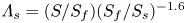 $\varLambda _s=(S/S_f)(S_f/S_s)^{-1.6}$ (where
  $S$,
$S$,  $S_f$,
  $S_s$ are, respectively, the platform area, the total frontal area and the total windward wetted area of the roughness) while
  $k_{rms}$ and
  $S_k$ are the r.m.s. and skewness of the roughness height fluctuations and
  $c_1$ and
  $c_2$ are constants.
The hydrodynamic length scale  $k_s$ appears to be correlated with different sets of geometrical parameters for each type of rough surface and no universal correlation currently exists for flow over surfaces of arbitrary roughness. For example, for synthetic roughness comprising closely packed pyramids (Schultz & Flack Reference Schultz and Flack2009) and random sinusoidal waves (Napoli et al. Reference Napoli, Armenio and De Marchis2008), it has been shown that
  $k_s$ scales on the effective slope when the surface slope is gentle (i.e. within the ‘waviness’ regime), whereas the skewness and r.m.s. height, but not slope magnitude, become important when the slope is steeper (i.e. within the ‘roughness’ regime). The boundary between these two regimes has been shown to be surface dependent (Yuan & Piomelli Reference Yuan and Piomelli2014a).
Some more recent studies of  $k_s$ correlations are summarized below. Thakkar, Busse & Sandham (Reference Thakkar, Busse and Sandham2017) carried out direct numerical simulation (DNS) of transitionally rough turbulent flows for different irregular roughness topographies. They found that the roughness function is influenced by solidity, skewness, the streamwise correlation length scale and the r.m.s. of roughness height. Flack, Schultz & Barros (Reference Flack, Schultz and Barros2020) performed several experiments to systematically investigate the effects of the skewness and amplitude of roughness height on the skin friction. They found that the r.m.s. and skewness of roughness height fluctuations are important scaling parameters for the prediction of roughness function; however, the surfaces with positive, negative and zero skewness values needed different correlations. Also, Chan et al. (Reference Chan, MacDonald, Chung, Hutchins and Ooi2015) simulated turbulent pipe flows over sinusoidal roughness geometries and confirmed strong dependence of roughness function on the average height and streamwise effective slope.
In previous studies, the small number of roughness parameters used to devise  $k_s$ correlations tended to limit their application to a narrow range of surface roughness. Since it appears that many geometrical parameters, such as porosity, moments of roughness height (e.g. r.m.s., skewness and kurtusis), effective slope and surface inclination angle might affect
  $k_s$, it is useful to employ a data science approach suited to modelling large multivariate/multioutput systems.
Specifically, we use machine learning (ML) to explore  $k_s$-prediction approaches that depend on a large set of surface-topographical parameters, with the expectation that the resulting models may be applied accurately to a wider range of surfaces. Since the prediction of
  $k_s$ from surface topography is essentially a labelled regression problem, supervised ML operations were performed using deep neural networks (DNN) and Gaussian process regressions (GPR). Both methods are explained thoroughly in § 3. Readers are referred to the monograph by Rasmussen & Williams (Reference Rasmussen and Williams2006) and the review provided by LeCun, Bengio & Hinton (Reference LeCun, Bengio and Hinton2015) for detailed descriptions of these methods.
An initial ensemble of 60 sets of data on  $k_s$ as a function of topographical parameters – 45 DNS results and 15 experimental results – was considered. All experimental data sets are fully rough, and of the DNS data, 30 are considered fully rough flows; all fully rough cases were used for ML training and testing. To the best of our knowledge, this ensemble of roughness geometries is the most extensive used for developing a
  $k_s$-prediction method.
In this paper, we first present the governing equations, solution methodologies, simulation parameters and different roughness topographies, and then discuss the post-processed DNS results used to calculate  $k_s$ for each surface. Finally, we describe the ML models, their predictions of
  $k_s$ and their uncertainty.
2. Problem formulation
2.1. Governing equations
The governing equations of incompressible continuity and linear momentum – the Navier–Stokes equations – for a constant-property Newtonian fluid, were solved by DNS. These equations are written in indicial notation as
 \begin{gather} \frac{\partial u_i}{\partial x_i} =0, \end{gather}
 \begin{gather}\frac{\partial u_i}{\partial t}+ \frac{\partial u_i u_j}{\partial x_j} =-\frac{\partial P}{\partial x_i} +\nu\frac{\partial^{2} u_i}{\partial x_j \partial x_j} + F_i, \end{gather}
where  $i,j=1,2,3$,
  $x_1, x_2$ and
  $x_3$ (or
  $x, y, z$) are the streamwise, wall-normal and spanwise coordinates, with corresponding velocity components of
  $u_1, u_2$ and
  $u_3$ (or
  $u, v, w$) and
  $P$ is defined as
  $p/\rho$, where
  $p$ is the pressure and
  $\rho$ is the fluid density;
  $\nu$ is the kinematic viscosity. An immersed boundary method (Yuan & Piomelli Reference Yuan and Piomelli2014b) was used to enforce the fine-grained roughness boundary conditions on a non-conformal Cartesian grid. The corresponding body force
  $F_i$ is added to the right-hand side of the momentum equations to impose a no-slip boundary condition at the fluid–roughness interface. To solve the equations, second-order central differencing was used for spatial discretizations and second-order Adams–Bashforth semi-implicit time advancement was employed. The numerical solver was parallelized using a message passing interface (known as MPI) method (Keating Reference Keating2004).
A double-averaging decomposition (Raupach & Shaw Reference Raupach and Shaw1982) was used to resolve turbulent and dispersive components of flow variables in the presence of roughness. In this decomposition, any instantaneous flow variable  $\theta$ may be decomposed into three components, as
 \begin{equation} \theta(\boldsymbol{x},t)=\left\langle\bar{\theta}\right\rangle(y)+\theta'(\boldsymbol{x},t)+ \tilde{\theta}(\boldsymbol{x}), \end{equation}
where the time-averaging operator is  $\bar {\theta }$ and the intrinsic spatial-averaging operator is
  $\left \langle \theta \right \rangle =1/A_f\int _{x,z}\theta \,\textrm {d}A$ (and
  $A_f(y)$ is the area occupied by fluid at an elevation
  $y$). The Reynolds and dispersive fluctuating components are then
  $\theta '=\theta -\bar {\theta }$ and
  $\tilde {\theta }=\bar {\theta }-\left \langle \bar {\theta }\right \rangle$, respectively. Here
  $\langle \bar {\theta }\rangle$ is called the double-averaged component.
The wall shear stress (including both viscous and pressure drag contributions on a rough wall) was determined by integrating the time-averaged immersed boundary method body force in the  $x$-direction
  $F_1$ as
 \begin{equation} \tau_w = \frac{\rho}{L_x L_z}\int_{\mathcal{V}} \overline{F_1}(x,y,z) \,\textrm{d}x\,\textrm{d}y\,\textrm{d}z, \end{equation}
where  $\mathcal {V}$ represents the simulation domain volume below the roughness crest and
  $L_{x_i}$ is the domain length in the
  $x_i$-direction. Readers are referred to Yuan & Piomelli (Reference Yuan and Piomelli2014b,Reference Yuan and Piomellic) for details of the implementation and validation of the immersed boundary method and the
  $\tau _w$ calculation.
2.2. Surface roughness
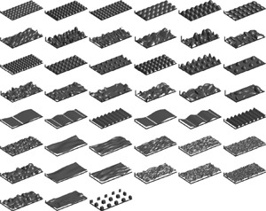
In figure 1, surface plots of the 45 roughness geometries used in these simulations are displayed; their statistical properties are given in table 1. Each case name in figure 1 and table 1 begins with the letter C or E, which denotes whether the data is computational or experimental, followed by an identifying index for that particular surface. For computational cases, this index is followed by: a characteristic length scale (as a percentage of  $\delta$) used for roughness synthesis; an identifier of whether the surface roughness is regular (reg) or random (rnd); and finally an identifier for one additional surface feature and its position in a series of surfaces with different sizes of that feature. These features were: the streamwise inclination angle
  $I_x$ in surfaces C01 to C12; the porosity
  $P_o$ in surfaces C13 to C24; and the streamwise effective slope
  $E_x$ in surfaces C25 to C30. For the experimental data two indices were assigned to each surface. The first denotes the year in which the data were published and the second is the surface designation in that publication. Thus surfaces with index 16 are from Flack et al. (Reference Flack, Schultz, Barros and Kim2016), those with index 18 are from Barros, Schultz & Flack (Reference Barros, Schultz and Flack2018) and those with index 19 are from Flack et al. (Reference Flack, Schultz and Barros2020). Note that these experimental data were obtained from fully developed channel flows, where the drag was measured through the pressure drop along the channel. Thus their results are expected to be more accurate than those of boundary layer studies where the drag is usually inferred.

Figure 1. Roughness geometries – each plot is a section of size  $\delta \times 0.5 \delta$ in the
  $x$–
$x$– $z$ plane. Cases C43 to C45 are from simulations with regular domain sizes (Yuan & Piomelli Reference Yuan and Piomelli2014a; Aghaei Jouybari, Brereton & Yuan Reference Aghaei Jouybari, Brereton and Yuan2019).
Table 1. Statistical parameters of roughness topography and the equivalent sand-grain height  $k_s$ for each roughness geometry. Here
  $R_a$,
  $k_{avg}$,
  $k_c$,
  $k_t$,
  $k_{rms}$ and
  $k_s$ values from DNS are normalized by the channel half-height
  $\delta$, while corresponding experimental values are given in mm;
  $k_s$ is not listed for cases thought to be transitionally rough.

Surfaces C01 to C24 were created using ellipsoidal elements (Scotti Reference Scotti2006) of different size, aspect ratio and inclination. For regular roughness, each element had the same orientation and semiaxis lengths,  $(\lambda _1,\lambda _2,\lambda _3) = (1.0, 0.7, 0.5)k_c$, where
  $k_c$ is the peak-to-trough height (also called the crest height). For random roughness, the elements had random orientations and semiaxis lengths (with uniform distributions of the random variables). The average orientation and semiaxis lengths for random roughness were the same as the corresponding regular surface. Surfaces C25 to C30 comprised sinusoidal waves in the
  $x$-direction, of the same magnitude but different wavelengths, to generate different values of effective slope
  $E_x$. The wavelengths were
  $3\delta /4$,
  $3\delta /8$ and
  $\delta /6$. Surfaces C31 and C37 comprised the random sand-grain roughness of Scotti, which were produced by randomly oriented ellipsoidal elements with fixed semiaxes of
  $(1.0, 0.7, 0.5)k_c$. Surfaces C32 to C36 and C38 to C42 were generated as the low-order (the first 5, 10, 20, 30 and 50) modes of Fourier transforms of white noise in the streamwise and spanwise directions; they therefore describe random surfaces with large- to small-wavelength roughness. Cases C43, C44 and C45 are DNS results from full-span channel computations of flow over surfaces of: random sand-grain roughness; the roughness found on a turbine blade (Yuan & Aghaei Jouybari Reference Yuan and Aghaei Jouybari2018); and arrays of cubes (from the study of Aghaei Jouybari et al. (Reference Aghaei Jouybari, Brereton and Yuan2019)), respectively. Case C46 is a full-span DNS of case C21, generated to validate the minimal-channel approach of the preceding cases. A baseline smooth-wall flow was also simulated using a full-span channel (Yuan & Aghaei Jouybari Reference Yuan and Aghaei Jouybari2018).
The geometric parameters reported for each surface in table 1 are: roughness peak-to-trough height (also termed crest height)  $k_c$ (i.e. distance between the highest and the lowest surface points); mean peak-to-trough height
  $k_t$ (i.e. the average of peak-to-trough heights obtained from surface tiles of size
  $\delta \times \delta$, similar to Forooghi et al. Reference Forooghi, Stroh, Magagnato, Jakirlic and Frohnapfel2017); mean roughness height
  $k_{avg}$; first-order moment of height fluctuations
  $R_a$; root mean square
  $k_{rms}$, skewness
  $S_k$ and kurtosis
  $K_u$ of the roughness height fluctuations; surface porosity
  $P_o$; effective slope in the
  $x_i$-direction
  $E_{x_i}$; and inclination angle (in radians) in the
  $x_i$-direction
  $I_{x_i}$, together with the hydrodynamic length scale
  $k_s$ deduced from the mean velocity field using (1.1).
These geometrical parameters are defined as
 \begin{gather} k_{avg} =\frac{1}{A_t}\int_{x,z}k\,\textrm{d}A, \end{gather}
 \begin{gather}R_a = \frac{1}{A_t}\int_{x,z}\vert k - k_{avg}\vert \,\textrm{d}A, \end{gather}
 \begin{gather}k_{rms} = \sqrt{\frac{1}{A_t}\int_{x,z} (k-k_{avg})^{2} \,\textrm{d}A} , \end{gather}
 \begin{gather}S_k = \left.\frac{1}{A_t}\int_{x,z}(k - k_{avg})^{3}\,\textrm{d}A \right/ k_{rms}^{3}, \end{gather}
 \begin{gather}K_u = \left.\frac{1}{A_t}\int_{x,z}(k - k_{avg})^{4}\,\textrm{d}A\right/ k_{rms}^{4}, \end{gather}
 \begin{gather}E_x = \frac{1}{A_t}\int_{x,z}\left|\frac{\partial k}{\partial x} \right|\textrm{d}A, \end{gather}
 \begin{gather}E_z = \frac{1}{A_t}\int_{x,z}\left|\frac{\partial k}{\partial z} \right|\textrm{d}A, \end{gather}
 \begin{gather}P_o = \frac{1}{A_t k_c}\int_0^{k_c} A_f \,{\textrm{d} y}, \end{gather}
 \begin{gather}I_x = \tan^{-1}\left\{\frac{1}{2}S_k\left(\frac{\partial k}{\partial x}\right)\right\}, \end{gather}
 \begin{gather}I_z = \tan^{-1}\left\{\frac{1}{2}S_k\left(\frac{\partial k}{\partial z}\right)\right\}, \end{gather}
where  $k(x,z)$ is the roughness height distribution and
  $A_f(y)$ and
  $A_t(y)$ are the fluid and total planar areas at each
  $y$ location. Here
  $S_k(\partial k/\partial x_i)$ is the skewness of the
  $\partial k/\partial x_i$ distribution. In table 1,
  $k_{avg}$,
  $k_c$,
  $k_{rms}$ and
  $k_s$ are then normalized by the first-order moment of height fluctuations
  $R_a$ and were incorporated in the ML algorithms in this form. All surfaces considered were in the ranges
  $k_c/\delta \leqslant 0.17$ and
  $R_a/\delta \leqslant 0.04$.
2.3. Simulation parameters
Direct numerical simulation was used to calculate the velocity and pressure fields in turbulent open-channel flows over 45 different rough surfaces and one smooth one, at a constant frictional Reynolds number  ${Re}_\tau =u_\tau \delta /\nu = 1000$, where
  $u_\tau$ is the friction velocity and
  $\delta$ is the channel half-height. In these simulations, the domain sizes were
  $(L_x, L_y , L_z)=(3, 1, 1)\delta$. The origin of the
  $y$ axis was the elevation of the lowest trough for each rough surface. The number of grid points was
  $(n_x, n_y , n_z)=(400, 300, 160)$. A uniform mesh was used in the
  $x$- and
  $z$-directions, yielding grid sizes of
  $\Delta x^{+}=7.5$ and
  $\Delta z^{+}=6.3$, where
  ${+}$ denotes normalization in wall units. For all cases, the mesh was stretched in the
  $y$-direction with a hyperbolic tangent function, with the third grid point from the origin at
  $y^{+} < 1$. For the rough-wall cases, at the roughness crest,
  $\Delta y/k_c \leqslant 0.017$, with this ratio taking its highest value for case C11. The maximum grid size was
  $\Delta y^{+}_{max}=9.5$ at the channel centreline, where the Kolmogorov length scale
  $\eta ^{+}\approx 6$. Moin & Mahesh (Reference Moin and Mahesh1998) have proposed that one requirement for obtaining reliable first- and second-order flow statistics is that the grid resolution must be fine enough to capture accurately most of the dissipation, while Moser & Moin (Reference Moser and Moin1987) noted that most of the dissipation in curved channel flow occurs at scales greater than
  $15\eta$ (based on average dissipation). It follows that for DNS computations of these kinds of flow statistics in channel and boundary-layer flows,
  $\Delta x/\eta$ and
  $\Delta z/\eta$ are typically chosen between 7 to 15 and 4 to 8, respectively (see, for example Kim, Moin & Moser Reference Kim, Moin and Moser1987; Spalart Reference Spalart1988; Yuan & Piomelli Reference Yuan and Piomelli2014c). The grid sizes in this study were chosen accordingly and were
  $\Delta x/\eta <7.5$,
  $\Delta y/\eta <4.0$ and
  $\Delta z/\eta <6.5$.
Periodic boundary conditions were imposed in the streamwise and spanwise directions, with no-slip and symmetry boundary conditions at the bottom and top boundaries, respectively. After each simulation had reached statistical stationarity, data were collected for ensemble averaging over 10 large-eddy turn-over times ( $\delta /u_\tau$). In these simulations, the time step
  $\tau ^{+} \leqslant 0.04$ and so was significantly smaller than the largest acceptable one of
  $\tau ^{+}\approx 0.2$ recommended by Choi & Moin (Reference Choi and Moin1994) for DNS.
The surface Taylor microscales  $\lambda _{T,x}$ and
  $\lambda _{T,z}$, in the
  $x$- and
  $z$-directions, were used to evaluate the adequacy of the grid resolution for resolving details of flow in the roughness sublayer, following Yuan & Piomelli (Reference Yuan and Piomelli2014b). These geometric microscales were obtained by fitting a parabola to the two-point autocorrelation of the surface height fluctuation in the respective direction. They represent the size of an equivalent ‘roughness element’ in the context of random multiscale roughness. The streamwise and spanwise values of
  $\lambda _T$, rescaled by
  $u_\tau /\nu$ as
  $\lambda _T^{+}$, and the respective grid sizes are given in table 2 (part I). For each case,
  $\lambda _{T,x_i}^{+}$ is of order
  $10$ to
  $10^{2}$, indicating that the average size of the roughness element is large in viscous units. On average, roughness elements were well resolved by the grid, with typically 4 to 12 grid points per
  $\lambda _{T,x_i}$ microscale in each direction. For reference purposes, Yuan & Piomelli (Reference Yuan and Piomelli2014a) reported a resolution of
  $\lambda _{T,x}/\Delta x\approx 4$ in their large-eddy simulations of channel flow over surfaces with sand-grain roughness. The cases in table 2 for which
  $\lambda _T$ was not well resolved in at least one direction (
 $\lambda _{T,x}/\Delta x < 3$ or
  $\lambda _{T,z}/\Delta z <3$) may also not have been fully rough flows (as discussed in the following section), and so were not included in the ensemble of flows for ML training and testing.
Table 2. Part I: streamwise and spanwise values of the surface Taylor microscale  $\lambda _T$. Part II: flow-related parameters obtained from DNS. The flow is assumed fully rough if
  $\hat {k}_s^{+}\gtrsim 50$, in which case
  $k_s$ is equal to
  $\hat {k}_s$.

In rough-wall flows, the pressure drag is caused primarily by the local flow structures and separation in the vicinity of individual roughness protuberances, which are predominately near-wall phenomena. To carry out the 46 separate DNS simulations for determining  $k_s$ efficiently, with sufficient near-wall resolution, a small-span channel simulation approach was employed. The concept of minimal-span simulation was introduced by Jimenez & Moin (Reference Jimenez and Moin1991). Chung et al. (Reference Chung, Chan, MacDonald, Hutchins and Ooi2015) and MacDonald et al. (Reference MacDonald, Chung, Hutchins, Chan, Ooi and García-Mayoral2017) carried out analyses of the performance of DNS over small spanwise domains for full and open channel flows on rough and smooth walls and showed that minimal-span simulations captured the essential near-wall dynamics and yielded accurate computations of wall friction, and of mean velocities and Reynolds stresses as far from the wall as
  $y\approx 0.3\delta$, when the following constraints were met:
 \begin{gather} L_x \geqslant \max\left(1000 \delta_\nu,3L_z,\lambda_{r,x}\right), \end{gather}
 \begin{gather}L_y \geqslant k_c/0.15, \end{gather}
 \begin{gather}L_z \geqslant \max\left(100\delta_\nu,k_c/0.4,\lambda_{r,z}\right), \end{gather}
where  $\delta _\nu =\nu /u_\tau$ and
  $\lambda _{r,x_i}$ is the characteristic roughness wavelength in the
  $x_i$-direction. Alternatively, the surface Taylor microscale may be used as the length scale in this constraint. Conditions (2.14a,c) were satisfied by choosing domain sizes
  $L_x^{+}$ and
  $L_z^{+}$ of 3000 and 1000, respectively, while condition (2.14b) was met for all cases except C11, which fell below the
  $L_y \geqslant k_c/0.15$ constraint by approximately 10 % – C11 is a case with random geometry; protuberances beyond
  $0.15\delta$ exist but are rare.
The criteria of (2.14) were developed originally for simulations of flow over surfaces with uniformly distributed roughness elements. In this study, the random roughness geometries used require an additional criterion on the sufficiency of the domain size: the area  $L_xL_z$ should be large enough to achieve statistical convergence of surface parameters, such as
  $k_{rms}$ and
  $E_{x_i}$, and of the flow parameter
  $k_s$. To check the adequacy of the chosen domain size, an additional simulation was carried out of case C21, the surface comprising the largest dominant spatial wavelength (and consequently the most limited sampling of random geometrical components with this wavelength) and a long-tailed height-fluctuation probability density function (p.d.f.) with a kurtosis of around 8. In this validation simulation, denoted case C46, the domain sizes were doubled in
  $x$ and
  $z$, by duplicating C21 in these directions. The double-averaged velocity profiles
  $U^{+}=\langle \bar {u}\rangle ^{+}(y^{+})$ for cases C21 and C46 are in a very good agreement over the log–linear region, as shown in figure 2. Each surface statistic differs by no more than 3 %, with the greatest discrepancy found in
  $I_z$, while the equivalent sand-grain roughness height
  $k_s$ is almost equal in the two cases. The chosen domain size was therefore considered sufficient for accuracy and convergence of statistics describing flow over the random roughness geometries of this study.

Figure 2. Profiles of streamwise double-averaged velocity plotted against a zero-plane-displacement shifted logarithmic  $y$ abscissa. The dashed lines are
  $u^{+}=y^{+}$ and
  $u^{+}=2.5\ln {(y-d)^{+}}+5.0$. The red dot-dash line in plot C46 is that of C21.
3. Results
3.1. Post-processed results
In figure 2, the streamwise double-averaged velocity profiles computed in these simulations are shown. The profiles in the logarithmic region are described for the smooth-wall case and the fully rough rough-wall cases as
 \begin{gather} \left\langle\bar{u}\right\rangle^{+} =\frac{1}{\kappa}\ln(y^{+})+5.0 \quad \text{and} \end{gather}
 \begin{gather}\left\langle\bar{u}\right\rangle^{+} =\frac{1}{\kappa}\ln\left(\frac{y-d}{k_s}\right)+8.5, \end{gather}
respectively, where  $d$ is the zero-plane displacement, obtained as the location of the centroid of the wall-normal profile of the averaged drag force (Jackson Reference Jackson1981). The shift in the
  $y$ coordinate by
  $d$ accounts for the flow blockage by surface roughness elements, and the values of
  $d$ are given in table 2 (part II).
To determine whether a particular flow was within the fully rough regime, (3.1b) was applied to the computed logarithmic velocity profile to yield a test value of  $k_s$, denoted as
  $\hat {k}_s$ in table 2 (part II). With
  $\hat {k}_s$ determined for all cases, those with
  $\hat {k}_s^{+}$ greater than a threshold value of 50 were deemed to be in the fully rough regime (30 surfaces), in which case
  $k_s$ was set to equal
  $\hat {k}_s$. Those below the threshold were possibly transitionally rough (15 surfaces) and so were not included in ML predictions in this study. The threshold value of
  $k_s^{+}$ – the lower end of the fully rough regime – has been observed to vary significantly for different types of roughness and is typically between 20 and 80. For example, the threshold values for surfaces C43 and C44 are roughly 80 and 20 (Yuan & Piomelli Reference Yuan and Piomelli2014a) and 50 for surface C45 (Bandyopadhyay Reference Bandyopadhyay1987).
The threshold value of  $k_s^{+}$ which signifies the beginning of the fully rough regime was not determined more precisely because of the cost of carrying out, for each surface, simulations at successively higher values of
  $k_s^{+}$ until
  $k_s/R_a$ became invariant with the Reynolds number. In the GPR prediction, potential uncertainties in
  $k_s$ which might arise through treating all flows with
  $k_s^{+}>50$ as fully rough, and other sources of possible error, were compensated for by incorporating an assumed 10 % noise level in the learning stage of the prediction of
  $k_s$, as discussed in § 3.2. The values of
  $k_s^{+}=50$ as the threshold for fully rough flows and the assumed noise level were chosen as part of a trade-off to maximize the number of usable data, to avoid overfitting, while acknowledging possible uncertainties in the modelling data.
In figure 3, pair plots of the different topographic roughness parameters are shown as scatter plots (lower left), joint p.d.f.s (upper right) and distribution p.d.f.s (diagonal). Pair scatter plots for the true (DNS and experimental) value of  $k_s$ and other roughness parameters are along the bottom row of this figure. It can be seen that, for the roughness cases chosen, there is some correlation between kurtosis and r.m.s. roughness (column 1, row 6), kurtosis and skewness (column 5, row 6) and skewness and porosity (column 2, row 5). The relationship between others appears to be more random. From the graphs in the bottom row, it can be seen that
  $k_s/R_a$ scales on porosity to some power, albeit with some scatter (column 2, row 7). It also appears that
  $k_s/R_a$ might decrease with skewness for surfaces with
  $S_k<0$ and increase with skewness in cases with
  $S_k>0$ (column 5, row 7). Surfaces with positive skewness yielded higher values of
  $k_s$ compared with those with negative skewness, consistent with the observation of Flack et al. (Reference Flack, Schultz and Barros2020). Beyond these observations, there does not appear to be a clear linear correlation between
  $k_s$ and any individual roughness parameter, which makes the search for a functional dependence of
  $k_s$ on these parameters a problem well suited to ML. The measures of inclination,
  $I_x$ and
  $I_z$, showed no clear correlation with other variables or with
  $k_s/Ra$.

Figure 3. Pair plots of geometrical parameters and  $k_s$, with
  $k_s$ plots in the bottom row and the first column, DNS data (blue), experimental data (red).
3.2. ML predictions of the equivalent sand-grain height
The ML techniques of DNN and GPR were employed to predict  $k_s$ from the data sets described in the previous section. The objectives of this exercise were to generate and collect data, and make qualitative comparisons between ML predictions and those from conventional correlations, rather than evaluating and comparing the performance of various ML procedures per se. The DNN and GPR approaches were used because our experience was that they predicted
  $k_s$ with high accuracy, notwithstanding their simplicity. Other approaches such as the support vector machine technique were considered initially, but their preliminary predictions were not as accurate as those found using DNN and GPR approaches.
The main characteristics of DNN and GPR methods are described below.
(i) The inputs for both techniques were 17 roughness geometrical parameters, eight of which were the primary variables
 $k_{rms}/R_a$, $I_x$, $\vert I_z \vert$, $P_o$, $E_x$, $E_z$, $S_k$ and $K_u$ (defined in (2.4) to (2.13)). The other nine were products of the primary variables, which were added to improve the efficiency of each learning stage. They were $p_1=E_xEz$, $p_2=E_xS_k$, $p_3=E_xK_u$, $p_4=E_zS_k$, $p_5=E_zK_u$, $p_6=S_kK_u$, $p_7=E_x^{2}$, $p_8=E_z^{2}$ and $p_9=S_k^{2}$. These particular products were chosen because of their perceived importance for certain types of roughness.
(ii) The database consisted of 45 different sets: 30 DNS of turbulent channel flows over different surfaces at
${Re}_\tau =1000$, and 15 experimental data sets at higher Reynolds numbers, with all data sets in the fully rough turbulent-flow regime.(iii) The DNN architecture was a multilayer perceptron, with three hidden layers (with 18, 7 and 7 neurons, respectively). The activation functions at all nodes were of the rectified linear unit kind, and kernel regularization was used to avoid overfitting. The network had 521 trainable weights in total. The preset parameters to the algorithm were optimized based on available data, through a hyperparameter tuning process. Specifically, 270 configurations were first generated with different lengths (representing the number of layers) and widths (representing the number of neurons). For each configuration, the DNN compiler was performed 1000 times with random selections of training (70 % of total) and testing (30 % of total) datasets to identify the best performance of the configuration. The configuration that yielded the best results was considered as the optimal one, the results of which are presented here. The cost of data fitting for one iteration (out of 1000) for each DNN configuration was approximately one second. In total, it took approximately 75 hours to obtain the optimal DNN network. This architecture was found to provide suitable accuracy in modelling without overfitting, for this particular multivariate labelled regression problem.
(iv) The GPR procedure used rational quadratic kernels to represent
$k_s$ as a superposition of scaled Gaussian functions of the independent variables of the modelling problem. Similar to the DNN method, the training and testing data were chosen randomly, with respective ratios of 70 % and 30 % of the total data points. The preset parameters (e.g. kernel type, number of iterations, etc.) were also tuned with the available data by running the GPR compiler approximately 8000 times. It took approximately 35 hours to obtain the optimal fit. The GPR method has the capability of incorporating uncertainty or noise in the determination of model parameters in the learning stages. Such noise might arise through: numerical and discretization errors; uncertainty in the form and model coefficients of equation (1.1); the applicability and fitting range of equation (1.1) (which was deduced from high Reynolds number experiments) to simulations at much lower Reynolds numbers; and the possibility that some of the training data may have been from simulations in which the flow was not quite fully rough. A noise level of 10 % in $k_s/R_a$ values was chosen as an upper estimate of the likely uncertainty from these sources. Noise levels of 5 % and 15 % were also tested, but little sensitivity of the $k_s$ prediction was found to the assumed noise level within the tested range.


The values of  $k_s$ predicted from the surface topography parameters, henceforth called
  $k_{sp}$, are compared with the actual
  $k_s$ values in figure 4, for the DNN and GPR methods, respectively. Scatter plots of
  $k_{sp}$ and the true value of
  $k_s$ in figures 4(a) and 4(d) reveal a tight clustering of data along the
  $y=x$ diagonal, with only a few outlying points. This very high degree of correlation between
  $k_{sp}$ and
  $k_s$ implies that both techniques have been applied with equal success to this prediction problem. The error range, figures 4(b) and 4(e), is less than
  $\pm 30$% (
 $L_\infty$ norm) and the average error (
 $L_1$ norm) is less than 8 %, for both techniques.

Figure 4. (a,d) Scatter plot of true  $k_s$ and predicted
  $k_s$, (b,e) scatter plot of true
  $k_s$ and relative error, (c,f) p.d.f.s of relative error, for (a–c) DNN and (d–f) GPR predictions, with DNS data (blue), experimental data (red).
The consistency between both the  $k_s$ predictions and error bands for two quite different ML techniques suggests that they are both well-suited to this kind of problem, and possibly close to an optimum for this class of ML approach.
The error values as percentages, for the DNN and GPR methods, are given in table 3, together with the error in the empirical relation
 \begin{equation} k_s=2.91k_{rms}(2+S_k)^{-0.284}, \end{equation}
proposed by Flack et al. (Reference Flack, Schultz, Barros and Kim2016) and
 \begin{equation} k_s=1.07k_{t}(1-\textrm{e}^{-3.5 E_x})(0.67 S_k^{2}+0.93 S_k +1.3), \end{equation}
given by Forooghi et al. (Reference Forooghi, Stroh, Magagnato, Jakirlic and Frohnapfel2017), as well as their respective recalibrated correlations
 \begin{gather} k_s=1.11k_{rms}(2+ S_k)^{0.74}, \end{gather}
 \begin{gather}k_s=0.04k_{t}(1-\textrm{e}^{-5.50 E_x})(S_k^{2}+2.57 S_k +9.82), \end{gather}
when extended to all cases in the current database. It is interesting to note that the form of equation (3.2) was chosen for surfaces generated by grit blasting – closely packed, random, three-dimensional (3-D) roughness with a wide range of scales (E01–E06), while many of the simulated surfaces are two-dimensional (2-D), some are characterized by discrete elements of similar sizes, while others are sparse or wavy (characterized by low slopes). Equation (3.3), on the other hand, includes a slope parameter and was calibrated for numerically generated surfaces consisting elements of random sizes and a prescribed shape.
Table 3. Errors in  $k_s$ prediction by DNN and GPR compared with errors of the empirical correlations:
  $err_{B1}$ (3.2),
  $err_{B2}$ (3.4),
  $err_{B3}$ (3.3) and
  $err_{B4}$ (3.5). The four largest errors (in magnitude) for each column are coloured in red. The errors are percentages.

For most cases, the errors from the DNN and GPR methods were of the same order of magnitude and much smaller than the error in using (3.2) or (3.3). In the DNN and GPR predictions of simulation cases, the greatest errors (approximately 25 %–30 %) arose in cases E07 and E08. The surfaces associated with these cases are characterized by fractal features (with spectral slopes of  $-0.5$ and
  $-1.0$, respectively (Barros et al. Reference Barros, Schultz and Flack2018)). The size of the errors for these cases might be attributed to the small number of surfaces with this feature used in the training set (as opposed to the many surfaces that are mostly characterized by single-scale elements). A close examination of the prediction errors for the DNS cases showed a subtle trend between relatively high errors and low roughness solidity (or low
  $E_s$ and insignificant wake sheltering), in, for example, cases C28 and C44. Both these cases are characterized by large-wavelength, wavy features, suggesting an under-representation of sparse roughness in the dataset. Beyond this observation, no clear correlation was found between the error and other primary roughness parameters included herein or surface categorizations (2-D/3-D, random/regular).
The errors associated with using (3.2) are small for surfaces E01 to E06, which were used to calibrate this relation. The errors in using (3.2) and (3.3) over all surfaces in the database are 120 % and 430 %, respectively. However, when recalibrated against the full database, (3.4) and (3.5) have a significantly smaller error band with maximum values of 79 % and 84 %. The high error values of the empirical correlations, compared with DNN or GPR prediction, are attributed to the small number of geometrical variables used in their calibrations and the restricted range of the models’ parameters.
3.3. Uncertainty estimation
In addition to predictions of equivalent sand-grain height, the GPR method provides confidence margins as functions of each input parameter. These margins can be useful for indicating the kinds of surfaces for which additional training data could improve confidence in predictions. This feature of the GPR approach makes it very attractive for studies of this kind, since DNS and experimental generation of data can be expensive.
The confidence intervals determined by the GPR technique are shown as functions of the normalized surface r.m.s. roughness height, effective slope, porosity and skewness in figure 5. Wider intervals indicate higher estimated values of predictive error, such as at roughness porosity of 0.68, and skewnesses of  $-1.5$ and 2.0. Surfaces of roughness with similar values of porosity and skewness would then be priorities for additional simulations or experiments.

Figure 5. Confidence interval ( $CI$) of predictions with the GPR method, with predicted values of
  $k_s/R_a$ in blue lines (called
  $k_{sp}$) and true values of
  $k_s/R_a$ in red dots. The GPR predictions for both training and testing data sets are shown –
  $k_s$ and
  $k_{sp}$ are very close to each other for the training data points, while they deviate (less than 30 % of error) for some test data points. Line jaggedness is associated with projection of a high-dimensional space to one-dimensional ones.
3.4. Sensitivity analysis
The dependence of DNN predictions of  $k_s$ on individual roughness parameters is explored by determining the change in the error norms when each of the primary surface parameters is removed from the data from which the DNN prediction was made. In table 4, the actual error for each surface, and the values of the
  $L_1$ and
  $L_\infty$ norms of errors in the prediction of
  $k_s$ over the 45 surfaces, are reported when the parameter(s) in the first row is (are) the excluded one(s). The errors of the base prediction (which includes all eight primary parameters) are listed in the second column. In the following discussion, we focus on the
  $L_1$ norm for ease of comparison over all 45 cases.
Table 4. Errors in  $k_s$ prediction by excluding one or two features. The base prediction includes all primary variables. The four largest errors (in magnitude) for each column are coloured in red. The errors are percentages.

When the values of  $L_1$ are considered, the relative importance of these surface parameters for predicting
  $k_s$ is
  $E_x$,
  $I_x$,
  $\vert I_z\vert$,
  $E_z$,
  $P_o$,
  $k_{rms}/R_a$,
  $S_k$ and, of least importance,
  $K_u$. The
  $L_1$-norm error is small when all parameters are included (7.4 %). Excluding any single one of these parameters increases the
  $L_1$-norm error up to around 9 %. On the other hand, the exclusion of
  $K_u$ from the input parameters does not worsen predictions of
  $k_s$ significantly. Instead, this observation appears to be a consequence of correlation between
  $K_u$ and other surface parameters like
  $k_{rms}/R_a$ (see figure 3). When such correlations exist and one correlating parameter is excluded, the DNN process redistributes the weightings given to other correlated parameters, with little loss in predictive accuracy.
To reduce the correlation between the excluded parameters and the remaining ones, one may exclude groups of parameters that are thought to characterize the same type of surface feature. For this reason, a sensitivity analysis was carried out on the effect of groups of variables on predictions of  $k_s$. The characteristics of surface slope, element inclination angle, porosity and intensity of height fluctuations, are contained in pairs of (
 $E_x$,
  $E_z$), (
 $I_x$,
  $I_z$), (
 $P_o$,
  $S_k$) and (
 $k_{rms}$,
  $K_u$), respectively. Parameters within each pair have been shown to be correlated to some degree in figure 3. Table 4 shows how the accuracy of
  $k_s$ prediction is affected, if any one of these pairs is excluded. According to the table, the prediction of
  $k_s$ is sensitive to all four pairs, but with greater sensitivities to the surface porosity (described by
  $P_o$,
  $S_k$) and the surface slope (described by
  $E_x$ and
  $E_z$). As expected, the elimination of both parameters of a pair worsens the prediction more than removing either single parameter (from around 7–9 % errors to up to 14 %).
According to the sensitivity analysis, all parameters considered are of some importance in the prediction of  $k_s$. The effective
  $x$-slope
  $E_x$ and roughness height skewness
  $S_k$ have been suggested as especially significant in earlier studies (Napoli et al. Reference Napoli, Armenio and De Marchis2008; Flack & Schultz Reference Flack and Schultz2010; Yuan & Piomelli Reference Yuan and Piomelli2014a). The inclination angle in the streamwise direction
  $I_x$ makes a significant contribution to the
  $k_s$ prediction because, physically,
  $I_x$ characterizes the average aerodynamic shape of the roughness elements. Surfaces with
  $I_x>0$ are aerodynamically bluff bodies when compared with surfaces of the same size but with
  $I_x=0$, and surfaces with
  $I_x<0$ tend to be more streamlined and hence produce less drag.
An important finding from this study is that the effective  $z$-slope
  $E_z$ is of similar importance to accurate
  $k_s$ prediction as
  $S_k$ or
  $E_x$. The exclusion of
  $E_z$ adversely affects the prediction for a large number of rough surfaces. Physically,
  $E_z$ describes whether the surface is close to a 2-D roughness with
  $E_z=0$ (such as a transverse bar roughness) or a 3-D roughness with finite
  $E_z$. It is known that a k-type 2-D roughness produces a higher drag than a 3-D roughness with the same height due to the larger spanwise length scale that the 2-D roughness imparts to the flow (Volino, Schultz & Flack Reference Volino, Schultz and Flack2009).
3.5. Comparison between ML algorithms and polynomial models
Explicit algebraic data representations, such as polynomial functions, can also be determined for the data sets of this study, using fitting or minimization procedures. In such methods, a set of basis functions is proposed for a model, the unknown coefficients of which are then optimized according to specified constraints. They are a generalization of the models of equation (1.2a–c), which were based on experimental observations of the dependence of  $k_s$ on a small number of surface parameters. A 30-degree-freedom polynomial basis was proposed as a ‘white-box’ model for
  $k_s$, analogous to a low-order Taylor series expansion for
  $k_s$,
 \begin{align} k_s/R_a &= \alpha_0 + \alpha_1 (k_{rms}/R_a)^{\alpha_2} + \alpha_3 I_x + \alpha_4 \vert I_x\vert^{\alpha_5} + \alpha_6 \vert I_z\vert + \alpha_7 \vert I_z\vert^{\alpha_8}\nonumber\\ &\quad + \alpha_9 P_o^{\alpha_{10}} + \alpha_{11}E_x^{\alpha_{12}} + \alpha_{13}E_z^{\alpha_{14}} + \alpha_{15}S_k + \alpha_{16}\vert S_k\vert^{\alpha_{17}} \nonumber\\ &\quad + \alpha_{18}(K_u-3) + \alpha_{19}\vert K_u-3\vert ^{\alpha_{20}} +\alpha_{21}(k_{rms}/R_a)^{\alpha_{22}}P_o^{\alpha_{23}} \nonumber\\ &\quad +\alpha_{24}(k_{rms}/R_a)^{\alpha_{25}}E_z^{\alpha_{26}} +\alpha_{27}P_o^{\alpha_{28}}E_z^{\alpha_{29}}, \end{align}
where  $a_i$ (
 $i=0,1,\ldots , 29$) are the model coefficients. To keep this model as simple as possible and to bring the effects of all contributing factors into account, we used terms as
  $\alpha _i \theta ^{\alpha _j}$ for a test variable
  $\theta$ that take only positive values (e.g.
  $k_{rms}$), and terms as
  $\alpha _i \theta + \alpha _j|\theta | ^{\alpha _k}$ for those variables that take both positive and negative values (e.g.
  $S_k$). For the latter, the power of
  $\theta$ in the first term is fixed (at one) instead of fitted, to eliminate the possibility of an imaginary number. Combinations of six parameters (
 $E_x$,
  $E_z$,
  $P_o$,
  $S_k$,
  $k_{rms}/Ra$ and
  $K_u$), taken in pairs, were also included. Since, for the present collection of surfaces, strong correlations were observed between individual variables within the three pairs of
  $(E_x,\,E_z)$,
  $(P_o,\,S_k)$ and
  $(k_{rms}/Ra,\,K_u)$, shown in figure 3, only one variable from each pair was used for the combination terms in (3.6). Using the other variable from any of these pairs instead would not lead to a significant change in the prediction using (3.6).
The high-dimensional space of  $a_i$ is poorly suited to curve-fitting and minimization procedures which use stochastic gradient descent algorithms. However, it is well suited to robust minimization methods like the differential evolution algorithm (Storn & Price Reference Storn and Price1997), with which global minima can often be found efficiently in spaces of high dimension. In this case, it is used to determine the values of the coefficients
  $a_i$ which minimize the
  $L_1$ norm.
In figure 6, the prediction quality of this white-box model with optimized coefficient values is shown. This method yields an average prediction error of 12 % and a maximum one of 51 % when using all 45 fully rough data sets (to give the best possible prediction accuracy) for the model training.

Figure 6. (a) Scatter plot of true  $k_s$ and predicted
  $k_s$ (denoted as
  $k_{sp}$), (b) scatter plot of true
  $k_s$ and relative error and (c) p.d.f. of relative error distribution for prediction using polynomial function defined in (3.6), with DNS data (blue) and experimental data (red).
The optimized values of  $a_i$ are

The predictive accuracy of this optimized explicit model equation is considerably lower than that of the DNN and GPR methods. One reason for this reduced accuracy is that low-order functions of geometrical parameters do not faithfully represent the dependence of  $k_s$ on surface parameters because each coefficient in the model is required to take the same value over the entire surface-parameter space. In ML approaches, such restrictions need not apply as they are not constrained to low-order polynomial functions but instead adopt a methodical search for the best representation of
  $k_s$ as a function of the surface parameters. This search is carried out through ‘feature selection’ in the first layers of DNN and the properties of the basis functions adopted in GPR, each of which are designed to yield the same mean and standard deviation of
  $k_s/R_a$ as in the original dataset (Rasmussen & Williams Reference Rasmussen and Williams2006).
4. Concluding remarks
The construction of a predictive model from a large ensemble of datasets for the equivalent sand-grain height  $k_s$ of a surface of arbitrary roughness, as a function of many different measures of surface topography, is a labelled regression problem that is well-suited to ML techniques. In this paper, data from 45 different rough surfaces (in fully rough flows) were used to devise DNN and GPR predictions for
  $k_s$ as functions of eight different surface-roughness parameters.
Both models were able to predict  $k_s$ for the 45 surfaces with an average error below 10 %, with the largest error for any one surface less than 30 %. These predictions were significantly better than those of existing formulae, and of a 30 degree-of-freedom polynomial model fitted to the same data, where the greatest error for any surface was approximately 50 %.
Sensitivity analyses revealed that inclusion of nearly all the surface roughness descriptive parameters was necessary to minimize the average prediction error, but that exclusion of either measures of porosity or measures of the surface slope increased the maximum prediction error more significantly than omitting other parameters.
Machine learning techniques are well suited to this modelling problem because: (i) it is complex in so far as different kinds of surface roughness yield different flow phenomena which are modelled most accurately in different ways, making the prospect of a general physical model very remote; and (ii) the dependent surface-roughness variables upon which  $k_s$ is modelled are a large non-orthogonal set for which robust multivariable regression techniques are required. As ML methods, they take no account of physical modelling concepts or observed phenomena within roughness sublayers, such as recirculation regions, enhanced turbulence production in the wake of roughness elements, assumed scalings for drag, etc., each of which is applicable to flows over some rough surfaces but not others. Nor are they hindered by the lack of orthogonality of the surface roughness parameters as the dependent variables of
  $k_s$. The techniques used can be configured readily to mimic models with very many degrees of freedom and, when compared with polynomial models, their feature selection properties provide the equivalent of different values for polynomial coefficients in different regions of the surface-parameter space. In this application, both approaches of DNN and GPR yielded models with very similar predictive accuracy, even though the techniques themselves were very different. We therefore conclude that they yield high-fidelity predictions of the equivalent sand-grain roughness height for turbulent flows over a wide range of rough surfaces, as a significant improvement over other methods. Improved prediction might be achieved by enlarging the database to include rough-wall flows with surface parameters which correspond to the relatively low prediction confidence in the GPR method, and by including additional roughness parameters as inputs which might describe sparseness and two-dimensionality, such as the solidity, correlation length scales and other two-point surface statistics.
In addition to the  $k_s$ prediction described here, the DNS database and the ML techniques in general can also be used to uncover relations between roughness geometry and physics-related quantities, such as the flow pattern around roughness protuberances, flow separation locations, characteristics of the shear layers associated with the separation bubbles, the wake sheltering volume, etc. Specifically, an ML network trained to correlate these flow characteristics (as outputs) to the roughness geometry (as inputs) may be an efficient tool for determining the sets of roughness geometrical features which are important for characterizing these effects. Knowledge of such a set of significant roughness parameters may also guide the construction of rough-surface databases that yield more efficient and more widely applicable predictions of
  $k_s$ or other quantities.
Supplementary materials
The rough-wall flow database (including  $k_s$, surface height map and surface parameters) and the trained DNN and GPR networks, called prediction of the roughness equivalent sand-grain height (PRESH), can be accessed online in the first author's GitHub repository at https://github.com/MostafaAghaei/Prediction-of-the-roughness-equivalent-sandgrain-height. With this package of data and programs, interested researchers can: (i) use the ML networks described in this paper to make predictions of
  $k_s$ for surfaces of their own roughness topography; (ii) download the code and train new DNN and GPR networks to predict
  $k_s$ for a different set of surfaces of arbitrary topography; and (iii) use the database of 45 rough-wall flows for other applications. It is recommended to use the ML configurations described in this paper for surfaces with parameters inside the ranges specified in figure 3. Extrapolations (using inputs which are beyond the specified range) will lead to additional uncertainty.
The PRESH and the database will be actively updated by the authors to improve the prediction accuracy and universality. We welcome interested researchers to share their datasets with us.
Acknowledgements
The authors gratefully thank Professor K.A. Flack of the US Naval Academy for providing the experimental data sets.
Funding
The authors gratefully acknowledge the financial support of the Office of Naval Research (award no. N00014-17-1-2102). Computational support was provided by Michigan State University's Institute for Cyber-Enabled Research.
Declaration of interests
The authors report no conflict of interest.


 Open access