






1. Introduction
We continue to analyse a flow problem of fundamental importance as started in our forerunner study (Scheichl, Bowles & Pasias (Reference Scheichl, Bowles and Pasias2018), hereafter referenced as Reference Scheichl, Bowles and PasiasSBP18).
Let a nominally steady and two-dimensional, developed, slender stream of a Newtonian liquid having uniform properties and at constant flow rate in an inertial frame of reference detach from a horizontal, solid, impenetrable, perfectly smooth plate with a trailing edge that is initially considered as abrupt and sharp. Downstream, the resulting fluid jet divides its gaseous environment, fully at rest and under constant pressures, into two parts. Here this picture is relaxed insofar as the upper one still defines the zero pressure level but we allow for a non-zero, constant support pressure prescribed at the downside of the detached layer. The body and interface forces crucially at play are the constant gravitational acceleration acting vertically towards the wetted side of the plate and surface tension. Based on the principle of least degeneration, our rigorous theoretical description of the detaching thin film under the assumption of very supercritical flow adopts a specific distinguished limit where the relevant Reynolds and Froude numbers are taken as asymptotically large but the corresponding Weber number as of  $O(1)$. Hence, the details accompanying the detachment process are governed by a strong viscous–inviscid, shortened-scale interaction at the outset of our present study.
Subsequently, we refer to the sketch in figure 1 throughout, illustrating the different flow regions considered when viewed on the global vertical scale defined by the height of the detaching layer. Specific interest is aroused by the so-called ‘teapot effect’, here observed in the flow in the immediate vicinity of the trailing edge and thus strongly affected by its microscopic geometrical resolution. As a start, we critically review the prevailing, rather phenomenological view on this effect and its previous modelling.

Figure 1. Global view on detaching film (not to scale, variables introduced in § 2.1): viscous sublayer (VSL), interactive flow comprising the main deck (MD) and the lower deck (LD), flow on smaller scales captured by green-shaded region, near wake of Hakkinen–Rott type (HRW).
1.1. The teapot effect: a digression
The frequently observed, at a first glance spontaneous (and often undesired) tendency of a liquid pouring from a spout to instead stick to its underside was originally reported and explained phenomenologically by Reiner (Reference Reiner1956, also see the references therein) and later by Walker (Reference Walker1984); see figure 2(a). More precisely, Reiner (Reference Reiner1956) coined the notion ‘teapot effect’ for pouring liquid along a rigid convex wall with a marked corner and adjoining to another (even liquid) fluid. He untangled the riddle of its occurrence experimentally: his observations ruled out the hitherto widely held belief that the wetting properties in terms of short-range inter-molecular adhesion forces, promoted by wetting agents, are its essential cause. However, his various experiments demonstrated that ‘adhesion’ as the reaction force on the fluid flowing over a solid phase as well as surface tension at its common interface with the surrounding fluid play a decisive role. A recent survey of the various treatments of this scenario presented by Jambon-Puillet et al. (Reference Jambon-Puillet, Bouwhuis, Snoeijder and Bonn2019, see the references therein) spans the rigorous approach within the framework of classical fluid mechanics, outlined below, to the nowadays more common but less stringent approach. This proposes that the pivotal cause for the fluid sticking lies in the hydrophilic tendency of the liquid/wall pairing rather than the mechanisms of the pouring. The latter authors provide new insight by coupling these ideas with classical arguments resorting to the first principles of continuum mechanics. Notably, Duez et al. (Reference Duez, Ybert, Clanet and Bocquet2010) indicate a significant reduction of the effect via the application of superhydrophobic substrates.
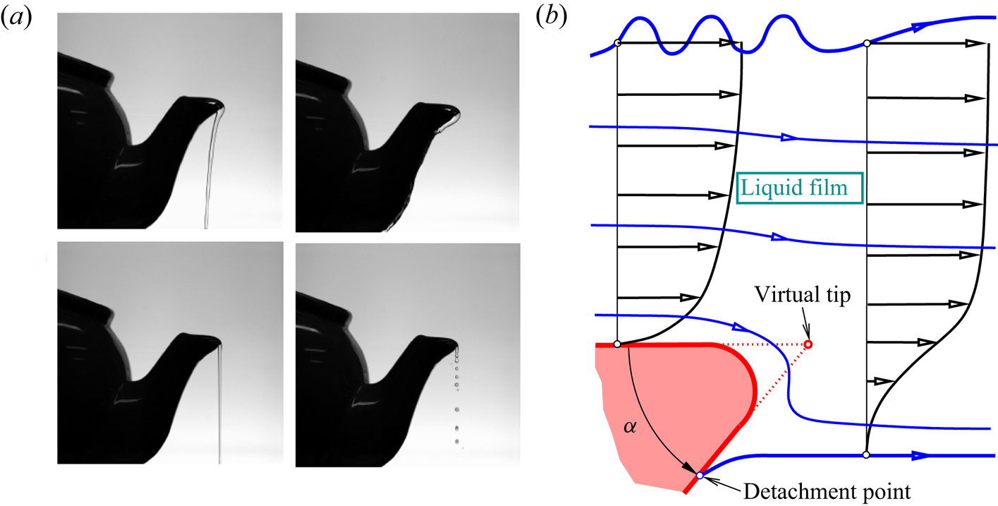
Figure 2. (a) Different realisations of the teapot effect for a low-momentum liquid film typically strongly subject to gravity, described in and reprinted with permission from Duez et al. (Reference Duez, Ybert, Clanet and Bocquet2010) (© the American Physical Society); (b) its current abstraction for a planar, horizontal high-momentum liquid film in fact passing a rounded wedge of angle  $\alpha$, detailing the flow around the trailing edge in figure 1, typical no slip on the plate and free slip along the free streamlines; blue: free and internal streamlines and detachment point, red: plate and original (virtual) tip in figure 1.
We advocate continuum mechanics for providing a satisfactory, rational unravelling of the effect. In agreement with the above mentioned early observations, we interpret it as a subtle interplay of inertia, capillarity and gravity in a two-dimensional setting. This is crucially tied in with the breakdown of viscous–inviscid interaction and, thus, the slender-layer approximation made on larger scales due to the assumed largeness of the globally defined Reynolds number of the oncoming attached flow. The significance of capillarity and inertia lies also in its proper adjustment immediately upstream of detachment. Our asymptotic theory proposes a fully rational account of the onset of this phenomenon in the realistic situation of a developed incident flow. As a specific ingredient, the trailing edge is replaced by a tip, i.e. a wedge formed by an acute cut-back angle or lip: this ‘attracts’ the liquid film such that it clings to it before the liquid sheet breaks away from it as a whole from its underside. This phenomenon of free rather than forced gross separation from a convex rigid surface, consequently referred to as the teapot effect from here onwards, does not yet have a satisfactorily rigorous and complete description. Duez et al. (Reference Duez, Ybert, Clanet and Bocquet2010) previously considered this ‘inertial-capillary’ mechanism, investigated here in depth and breadth, as a crucial step towards a breakthrough in the explanation of the effect.
An initial self-consistent clarification of the effect benefited from the quite restrictive assumption of irrotational free-surface flow of a weightless ideal fluid and the neglect of surface tension past a horizontal plate, terminated by the aforementioned lip: remaining firmly attached both with the neglect of gravity (Keller Reference Keller1957) and under gravity (Vanden-Broeck & Keller Reference Vanden-Broeck and Keller1986); detaching grossly from the underside at zero gravity (Vanden-Broeck & Keller Reference Vanden-Broeck and Keller1989). In these investigations, the flow is stipulated to cling to the wall and, due to the absence of viscosity, the position of detachment is also prescribed (Vanden-Broeck & Keller Reference Vanden-Broeck and Keller1989). However, then the well-known Brioullin–Villat condition, met for vanishingly small effects of capillarity (and viscosity), fixes the physically admissible detachment point.
Rather little is known when it comes to the rigorous inclusion of viscosity in this flow picture. At least, the passage of a layer over an asymptotically small convex wall corner (and in related situations) considered by Gajjar (Reference Gajjar1987) (and the refined numerical results by Yapalparvi Reference Yapalparvi2012) is relevant. Specifically, there the unperturbed oncoming flow is fully developed (so as to model a real situation), as being already inclined towards gravity, and viscous–inviscid interaction of the double-layer structure in the high-Reynolds-number limit, adopted here, negotiates the slender obstacle which the corner forms. However, the counteracting impact of surface tension in the resulting combined hypersonic- and wall-jet-type interaction law (cf. Bowles & Smith Reference Bowles and Smith1992) is ignored in the analysis although mentioned. Although the interactive flow considered by Gajjar (Reference Gajjar1987) is assumed to remain grossly attached, it is certainly interesting that the numerical solutions predict a closed separation bubble beyond the mild wedge for both sufficiently large turning angles and Froude numbers.
A seminal reference for the teapot effect in a realistic, i.e. developed, flow is the numerical and partially analytical investigation of the full Navier–Stokes problem by Kistler & Scriven (Reference Kistler and Scriven1994). They unambiguously highlighted its viscous and capillary, i.e. hydrodynamic, nature as underpinned by experimental evidence. This prompted them to conclude that ‘the teapot effect is more than merely an issue of wetting’. Most remarkably, they pointed out how the restrictions of the microscopic wedge-type geometry of what is on larger scales viewed as an ‘infinitely sharp’ edge implies a contact-angle hysteresis, associated with non-unique flow states, but the point of flow detachment becomes the apex of the wedge when the jet Reynolds number, i.e. the momentum it carries, becomes sufficiently large. The present asymptotic analysis corroborates this finding, where we deal with a horizontal oncoming flow past a wedge originally represented by a cut-back angle  $\alpha$ ( ${0<\alpha <{\rm \pi} }$), using equal horizontal and vertical scales. However, here the wedge is no longer necessarily sharp as we allow for its tip being realistically rounded; see the sketch in figure 2(b).
1.2. Studied phenomena and open questions
Our current concern is with the analytical/numerical challenges arising in the analysis of the free jet with particular emphasis placed on the description of its detachment at the abrupt plate edge on the smallest scales and the freely interacting flow immediately downstream of the trailing edge. As a key observation in Reference Scheichl, Bowles and PasiasSBP18, the free layer is strongly dependent on its history and, therefore, of the no-slip condition satisfied upstream of its detachment. Since the interaction mechanism is not alone capable of smoothing the flow quantities at the sharp edge, coping with this demand addresses the flow on still smaller and down to the smallest scales discernible and eventually the wetting properties of the plate as well as the detailed geometry forming its edge. The following threefold conclusions drawn from such an analysis attempt to shed light on some unsettled questions of fundamental interest.
(i) As a first cornerstone, it reveals the existence of (stationary) undamped capillary Rayleigh modes upstream of its break-away from the plate.
(ii) The multi-layer slenderness of the flow, given the largeness of the Reynolds number, prevents its separation upstream of the trailing edge, which confirms the initially made assumption of detachment ‘at the edge’ considered on larger scales.
(iii) As a second highlight, the implied wetting of the edge suggests a novel, rational explanation of the teapot effect observed in a high-momentum liquid layer when a convex corner provides – in a most simple but nevertheless sufficiently complex manner – the non-degenerate geometry modelling the plate edge.
1.3. Organisation of the paper, used notation and numerical software
The process of asymptotic scale separation, starting with the largest global scale down to the smallest ones where the teapot effect is at play, guides the structure of our study. Visualising this in figure 3 serves to illustrate and accompany the subsequent analysis of the individual flow regimes governed by those spatial scales. Hence, figure 3( f) recovers the linkage to the teapot effect as in figure 2. From here onwards, we adopt the abbreviations of the flow regions as introduced in figures 1 and 3.
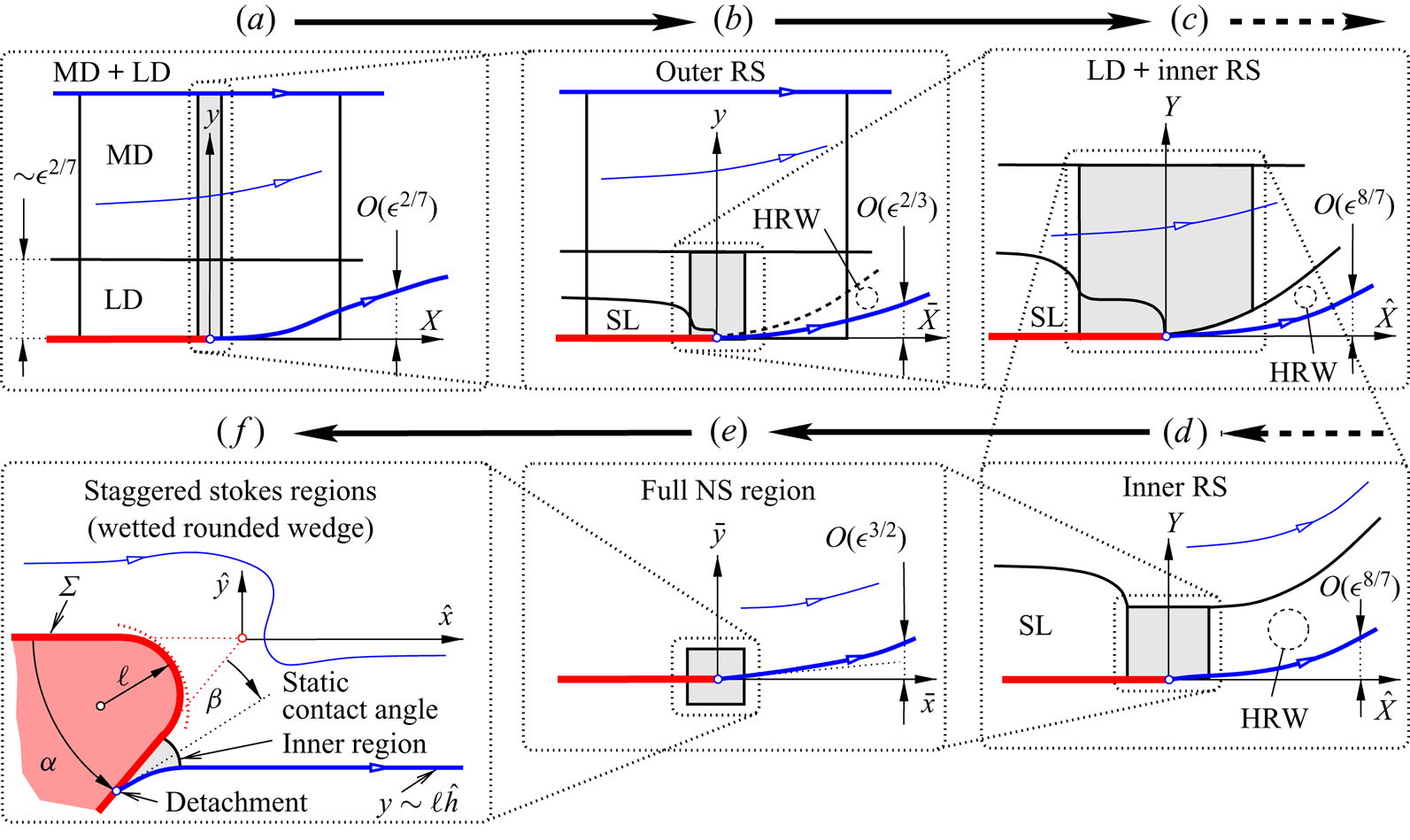
Figure 3. Essential flow regions, shaded details zoomed-in consecutively clockwise from (a) to ( f) (not to scale, scales in relation to global ones  $x$ and $y$, denotations provided in the course of the analysis): flow detachment viewed on interactive down to smallest scales, where the detached streamline is no longer elongated and the flow no longer slender; MD, LD, the inner and outer Rayleigh stages (RSs), HRW in (b) as sublayer of LD (dashed boundary); slip layer (SL) at bottom of LD below outer RS, Navier–Stokes (NS) regime; blue: free and internal streamlines and detachment point, red: plate and original tip, coinciding with origin and detachment point in (a–e), all disparate in resolved situation ( f) (§ 4.3).
The remainder of this study is organised as follows.
Section 2: We first pose the problem based on first principles in full. Our basic scaling arguments (§ 2.1 and Appendix A) justify the use of asymptotic analysis as the means of choice to study the flow, initiated by completing the formulation of the interaction problem, originally posed in Reference Scheichl, Bowles and PasiasSBP18. It then governs the continuation of the freely interacting jet downstream of the edge in a rigorous manner as long as the value of the appropriately rescaled Weber number does not fall below a certain threshold, so avoiding the onset of nonlinear stationary capillary waves even above the plate (§ 2.2 and Appendix B). Over the interactive streamwise scale, this brings into play the splitting of the film into the MD and the LD, this initiated by a VSL adjacent to the plate.
Section 3: A multi-structured small-scale flow, essentially controlled by capillarity only (§ 3.1), supersedes locally the two-tiered interactive one. The HRW forming at the base of the LD just downstream of the plate (§ 3.2) is central for understanding the multi-structured small-scale flow locally superseding the two-tiered interactive one. Its thorough investigation reveals two nested square Euler regions (§ 3.3). These outer and inner RSs govern weak perturbations around the flow at detachment. The exterior one extends vertically across most of the layer and is the source of phenomenon (i) above on the top free surface. Simultaneously, a viscous (passive) SL forms at the base of the predominantly inviscid flow.
Section 4: This essentially inviscid description of flow detachment paves the way for a full NS regime detected on even smaller streamwise and vertical scales, where the flow structure of § 3 collapses. (§ 4.1). Its analytical study leads to the implication (ii) above (§ 4.2). As a pivotal finding, achievement (iii), we also identify one or two interlaced Stokes regions resolving the smallest scales and the actual wedge-type resolution of the plate end (§ 4.3, figure 3 f), until now seen as infinitely thin. Consequently, it is this flow regime where the break-away of the film, interacting with the larger-scale flow through the NS region, is finally controlled by both the effective edge geometry and the static wetting angle. Thereby, an awareness of the close relationship of this situation to the teapot effect is gained.
Section 5: Surveying the current results and anticipating the inclusion of, for example, unsteadiness and the aforementioned capillary undulations in our ongoing research completes the study.
So as not to distract attention away from the main arguments and their physical impact, the detailed steps of the asymptotic analysis, together with further technical side aspects, potentially of interest for the more mathematically orientated readership, are put forward as the accompanying ‘Other supplementary material’ available at https://doi.org/10.1017/jfm.2021.612. It consists of the individual supplements A–E. Cross-references between these, its numbered subsections and the main document are conveniently employed. We add citations exclusively in the supplement to the list of references.
In addition to the usual conventions for mathematical expressions, we adopt the following usage of accents and sub- and superscripts (cf. figure 1). Indices typically indicate orders in asymptotic expansions and partial derivatives unambiguously, and lowered ‘ $-$’ and ‘ $+$’ refer to respectively the lower and upper boundaries of the liquid layer (e.g. $h_-$ and $h_+$) or the states of the flow infinitely far upstream (‘ $-$’) and downstream (‘ $+$’). We endow dimensional quantities with tildes. Furthermore, we attempt a systematic as possible denotation of the dependent and independent $O(1)$-variables characteristic of the individual regimes: lowercase for the MD (e.g. $x$), capitalised for the LD ( $X$), capitalised with overbars for the outer RS ( $\bar {X}$), capitalised with hats for the inner RS ( $\hat {X}$), lowercase with overbars for the full NS region ( $\bar {x}$), lowercase with hats for the Stokes regions ( $\hat {x}$).
All our numerical calculations used the widely used, proprietary programming language and numerical-computing environment MATLAB (The MathWork Inc 2020), supplemented with the NAG Toolbox (The Numerical Algorithms Group (NAG) 2020). In particular, the computations benefit from its convenient handling of complex arithmetic and the, in principle, built-in arbitrarily high accuracy and precision.
2. Statement of the extended problem
It proves expedient to first reappraise the fundamental assumptions and the problem in full before revisiting the interactive limit.
2.1. Non-dimensional groups and governing equations
The problem has the following central ingredients. The slender layer of density  $\tilde {\rho }$ and kinematic viscosity $\tilde {\nu }$ and experiencing a tensile surface stress $\tilde {\tau }$ and gravitational acceleration $\tilde {g}$ carries a volume flow rate per lateral unit width $\tilde {Q}$. It adjusts to a developed state over some sufficiently large distance $\tilde {L}$, serving as the basic length scale and measured along the plate from its trailing edge in the upstream direction. Simultaneously, $\tilde {L}$ is required to be so short that the vertical layer height has not grown sufficiently to allow for a significant impact of the hydrostatic pressure on streamwise convection. Then a layer height ${\tilde {H}=\tilde {L}\tilde {\nu }/\tilde {Q}}$ and flow speed ${\tilde {U}=\tilde {Q}^{2}/(\tilde {\nu }\tilde {L})}$ representative of this near-supercritical film follow from conservation of the flow rate and the streamwise momentum, here expressed by the balance between convection and the shear stress gradient, respectively,
 \begin{equation} \tilde{Q}=\tilde{U}\tilde{H},\quad \tilde{U}^{2}/\tilde{L}=\tilde{\nu}\tilde{U}/\tilde{H}^{2}. \end{equation}
In many applications, the vertical height and, accordingly, the speed of the layer have respectively increased and decreased so markedly over  $\tilde {L}$ that it has almost attained its well-known perfectly supercritical, fully developed or self-preserving state discovered by Watson (Reference Watson1964): for related discussions, see Bowles & Smith (Reference Bowles and Smith1992), Higuera (Reference Higuera1994) and, in the context of an axisymmetric and rotatory layer generated by vertical jet impingement, Scheichl & Kluwick (Reference Scheichl and Kluwick2019).
The flow is then controlled by the slenderness parameter or reciprocal Reynolds number  $\epsilon$ and corresponding reciprocal Froude and Weber numbers $g$ and $\tau$,
 \begin{equation} \epsilon:=\frac{\tilde{H}}{\tilde{L}}=\frac{\tilde{\nu}}{\tilde{U}\tilde{H}}\ll 1,\quad g:=\frac{\tilde{g}\tilde{H}}{\tilde{U}^{2}}=O(\epsilon^{4/7}),\quad \tau:=\frac{\tilde{\tau}}{\tilde{\rho}\tilde{U}^{2}\tilde{H}}=O(1). \end{equation}
Regarding the distinguished limit involving  $g$, a locally strong viscous–inviscid interaction describes the abrupt transformation of the wall-bounded flow on crossing the lip towards the free liquid jet in a least-degenerate, self-consistent and sufficiently smooth manner. We remark that the conventionally defined capillary number
 \begin{equation} {{Ca}}:=\tilde{\rho}\tilde{\nu}\tilde{U}/\tilde{\tau}=\epsilon/\tau\ll 1 \end{equation}
or the alternative Ohnesorge number, here  ${\epsilon /\sqrt {\smash [b]{\tau }}\ll 1}$, provide different albeit less preferable measures of the surface tension for a layer of slenderness expressed by $\epsilon$: since the streamline curvature scales with ${\tilde {H}/\tilde {L}^{2}=\epsilon ^{2}/\tilde {H}}$, the ratio of the viscous (deviatoric) stress, normal to a free surface and scaling with ${\tilde {\rho }\tilde {\nu }\tilde {U}/\tilde {L}=\tilde {\rho }\tilde {U}^{2}\epsilon ^{2}}$, to the capillary hoop pressure measured by ${\tilde {\tau }\tilde {H}/\tilde {L}^{2}=\tau \epsilon ^{2}\tilde {\rho }\tilde {U}^{2}}$ is expressed by the augmented capillary number ${{\textit {Ca}}/\epsilon =1/\tau =O(1)}$, taking into account the aspect ratio of the flow. This indicates that in the limit provided by (2.2a) the surface jump of the total normal stress is fully retained in the dynamic boundary conditions (BCs) below.
Order-of-magnitude arguments considering realistic flow situations support the above asymptotic scaling and demonstrate its applicability to the teapot phenomenon in typical settings; see Appendix A.
We introduce Cartesian coordinates  $x$ and $y$ pointing respectively horizontally from the trailing edge and vertically towards the flow, the streamfunction $\psi$ and the pressure $p$, non-dimensional with $\tilde {L}$, $\tilde {H}$, $\tilde {Q}$ and $\tilde {\rho }\tilde {U}^{2}$, respectively. Then $u:=\psi_{y}$ is the horizontal and ${v:= -\epsilon \psi _x}$ the vertical flow component made dimensionless with $\tilde {U}$. These $O(1)$-quantities satisfy the NS equations in the form
 \begin{gather} \psi_y\psi_{yx}-\psi_x\psi_{yy} ={-}p_x+(\epsilon^{2}{\partial}_{xx}+{\partial}_{yy})\psi_y, \end{gather}
 \begin{gather}\epsilon^{2}(\psi_x\psi_{yx}-\psi_y\psi_{xx}) ={-}p_y-(\epsilon^{2}{\partial}_{xx}+{\partial}_{yy})(\epsilon^{2}\psi_x)-g. \end{gather}
Here and hereafter, the subscripts  $-$ and $+$ indicate the evaluation along the lower and the uppermost free streamline, respectively. Accordingly, ${y=h_-(x)}$ ( ${\equiv 0}$ for ${x\leq ~0}$) and ${y=h_+(x)}$ denote their positions; hence, ${h(x):= h_+ -h_-}$ the vertical film thickness and $p_\pm$ the given pressure levels along the free streamlines. Adopting the Heaviside step function $\theta$ then gives the kinematic boundary conditions including the conventional requirements of no slip at and no penetration through the plate as
 \begin{equation} y=h_-(x)\colon\enspace \psi=\psi_y\theta({-}x)=0,\quad y=h_+(x)\colon\enspace \psi=1. \end{equation}
The dynamic BCs express vanishing tangential stresses and total normal stresses equal to the capillary pressure jumps on the free surfaces of curvatures  $\varkappa _\pm (x)$ and subject to the Young–Laplace equilibrium. Therefore, at
 \begin{gather} y=h_-(x)\quad \text{if}\ x>0,\quad y=h_+(x)\colon \notag\\ (1-\epsilon^{2} h_\pm'^{2})(\psi_{yy}-\epsilon^{2}\psi_{xx})-4\epsilon^{2} h_\pm'\psi_{yx}=0, \end{gather}
 \begin{gather} \left.\begin{array}{c@{}} 2\epsilon^{2}[\psi_{yx}(1-\epsilon^{2} h_\pm'^{2})+h_\pm'(\psi_{yy}-\epsilon^{2}\psi_{xx})]/(1+\epsilon^{2} h_\pm'^{2})+ p-p_\pm{=}\tau\varkappa_\pm,\\ p_+{=}0,\quad \varkappa_\pm{=}\mp\epsilon^{2} h_\pm''/(1+\epsilon^{2} h_\pm'^{2})^{3/2}. \end{array}\right\} \end{gather}
This completes the problem (2.3) as proper up- and downstream conditions will be condensed into requirements of continuity holding at the trailing edge  ${x=0}$.
2.2. Free interaction across the trailing edge
The governing equations (2.3) and (2.2a) immediately give rise to regular expansions valid for the flow above the plate on the original large streamwise scale, i.e. for  ${1+x=O(1)}$, ${0>x=O(1)}$,
 \begin{gather}{} [\psi,h,p/g] \sim [\psi^{0}(x,y),h^{0}(x),h^{0}(x)-y]+O(g)\quad (\epsilon{\rightarrow 0}), \end{gather}
 \begin{gather}{} [\psi^{0},h^{0}] \sim [\psi_0(y),h_0]+O(x)\quad (x{\rightarrow 0}-). \end{gather}
In the leading order of this non-interactive limit, the classical parabolic shallow-water approximation of (2.3) is recovered, predicting a pressure-free base flow described by  $\psi ^{0}$ and $h^{0}$. These quantities approach regularly some values $\psi _0$ and $h_0$ at the trailing edge. The higher-order contributions in (2.4a) control the modification by the hydrostatic pressure distributions and non-parallel-flow effects, the latter predominantly due to streamline curvature, capillary action and the viscous normal stresses $\pm \epsilon ^{2}\psi _{yx}$, in the following iterative manner. At each level of improvement, the obtained approximation for $\psi$ feeds into (2.3b) subject to (2.3e). The resulting pressure correction then forces a problem that emerges from expanding (2.3a) subject to (2.3c) and (2.3e) and governs a further correction for $\psi$, and so on.
Following Reference Scheichl, Bowles and PasiasSBP18, this hierarchy is singularly perturbed by weak irregular disturbances exhibiting exponential growth over a short streamwise scale measured by  $\epsilon ^{6/7}$. Thus, they are active in the VSL adjacent to the plate. Hence, subject to free viscous–inviscid interaction governed by streamline curvature, not accounted for in the classical shallow-water limit, they describe the intrinsic upstream influence in the film caused by both gravity and capillarity. Finally, the growth of these two effects renders the above hierarchy invalid around the trailing edge where ${x=O(\epsilon ^{6/7})}$ and they provoke a locally strong interaction over that scale in the limits (2.2a). This typically involves a nonlinear distortion of the strongly viscosity-affected slow flow in the LD, here originating from the VSL, adjacent to the lowermost streamline where ${y=O(\epsilon ^{2/7})}$. The latter exerts a linear response in the MD that comprises the bulk of the layer, beneath the upper free streamline.
The background flow enters the interactive scalings at leading order solely through two quantities condensing its upstream history: the momentum flux  $J$ at the trailing edge and the shear stress $\lambda$ exerted on it:
 \begin{equation} J:=\int_0^{h_0}\psi_0'^{2}(y)\,\text{d} y,\quad \lambda:=\psi_0''(0) \quad \text{as}\quad \psi_0\sim\frac{\lambda y^{2}}{2}+\frac{\lambda\omega y^{5}}{60}+O(y^{8})\quad (y{\rightarrow 0}). \end{equation}
The coefficient  $\omega$ is only relevant in the small-scale analysis of § 3.3.2. We also note (2.3c) and the free-slip condition resulting from (2.3e),
 \begin{equation} \psi_0(h_0)=1,\quad \psi_0''(h_0)=0. \end{equation}
Usually,  $\tilde {H}$ is definitely larger than the height of the film immediately downstream of its origin (as given by jet impingement) and where the flow starts to become developed; see table 1 in Appendix A. This prompts us to assume that the base flow is already described by Watson's (Reference Watson1964) self-similar solution and thus to neglect the small deviations from this due to the flow history, as in Reference Scheichl, Bowles and PasiasSBP18 and without any substantial loss of generality. In this idealisation, ${h^{0}={\rm \pi} (x-x_v)/\sqrt {\smash [b]{3}}}$ provided some ${x=x_v<0}$ indicates the virtual origin of the fully developed flow and $\psi ^{0}$ is a universal function of $y/h^{0}(x)$. At ${x=0}$, $\psi _0$ then satisfies
 \begin{equation} \psi_0'^{2}(y)=x_v\psi_0'''(y) \end{equation}
and has an exact representation given by Scheichl & Kluwick (Reference Scheichl and Kluwick2019): writing  ${u_0^{+}:=\psi _0'(h_0)}$ from here on, this implies the important canonical results
 \begin{equation}
\left.\begin{array}{cc@{}}
h_0/|x_v|={\rm \pi}/\sqrt{\smash[b]{3}}\simeq 1.8138,\quad
|x_v|u_0^{+}=\left[\mathrm{\Gamma}\left(\tfrac{1}{3}\right)/\mathrm{\Gamma}\left(\tfrac{5}{6}\right)\right]^{2}/(2{\rm \pi})\simeq
0.89644, \\
x_v^{2}\lambda=|x_v|J=\sqrt{\smash[b]{2/3}}\left(|x_v|u_0^{+}\right)^{3/2}\simeq
0.69301. \end{array}\right\}
\end{equation}
\begin{equation}
\left.\begin{array}{cc@{}}
h_0/|x_v|={\rm \pi}/\sqrt{\smash[b]{3}}\simeq 1.8138,\quad
|x_v|u_0^{+}=\left[\mathrm{\Gamma}\left(\tfrac{1}{3}\right)/\mathrm{\Gamma}\left(\tfrac{5}{6}\right)\right]^{2}/(2{\rm \pi})\simeq
0.89644, \\
x_v^{2}\lambda=|x_v|J=\sqrt{\smash[b]{2/3}}\left(|x_v|u_0^{+}\right)^{3/2}\simeq
0.69301. \end{array}\right\}
\end{equation}
Table 1. Typical input data (water at standard conditions) and output  $\tilde {H}$, $\tilde {U}$.

The interaction process itself is parametrised by suitably redefined reciprocal Froude and Weber numbers  $G$ and $T$ and the rescaled support pressure $P_-$, all of $O(1)$. Specifically, $T$ is formed with the local momentum flux and thus measures the influence of capillarity relative to fluid inertia. We thus introduce
 \begin{equation} (G,P_-):= (g h_0,p_-)/(M^{2}\lambda^{6}\epsilon^{4})^{1/7},\quad T:=\tau/J,\quad M:=|T-1|J=|\tau-J|. \end{equation}
The above propositions enable us to reconsider the interaction problem, at first under the assumption that  $T$ is not too close to unity. For the details of its numerical treatment by specifying $\psi _0$ as Watson's flow profile and marching downstream, we refer to Reference Scheichl, Bowles and PasiasSBP18.
The given adjustment length  $\tilde {L}$ serves to define $\tilde {H}$ and $\tilde {U}$ via (2.1a,b). Hence, for a given flow, we note the invariance of (2.1a,b) and thus of $\epsilon$, $\psi$, (2.3) and $G$,
$G$,  $T$,
$T$,  $P_-$ under the affine transformation
 \begin{equation} \left(\tilde{L},\tilde{H},\tilde{U},x,y,h_\pm,p,g,\tau,J,\lambda\right)\mapsto \left(a\tilde{L},a\tilde{H},\frac{\tilde{U}}{a},\frac{x}{a},\frac{y}{a},\frac{h_\pm}{a},a^{2} p,a^{3} g,a\tau,a J,a^{2}\lambda\right) \end{equation}
with  ${a>0}$ being an arbitrary scaling factor. This confirms the independence to $\tilde {H}$ of the canonical formulation of the interaction problem below and, thus, on the specific choice of the streamwise length scale $\tilde {L}$ (for a sufficiently small ${\epsilon =\tilde {H}/\tilde {L}}$). In particular, its solution downstream of the edge does not depend on the scaling of the attached flow and, specifically, the position of the aforementioned virtual origin. For any subsequent numerical evaluation involving $\psi _0$ and $h_0$, however, we not only assume the flow as being fully developed but also adopt the natural standardisation ${x_v=-1}$ from here on, i.e. we specify $\tilde {L}$ to be the full development length.
2.2.1. Main deck
Since the MD describes a predominantly inviscid flow in the long-wave limit, the central local expansion reads as
 \begin{align} \left[\psi,h,h_-,h_+\right] &\sim \left[\psi_0(z),h_0,0,h_0\right]+ \epsilon^{2/7}m\left[A(X)\,\psi_0'(z),-A(X),H_-(X),H_+(X)\right] \nonumber\\ &\quad + O(\epsilon^{4/7}),\quad H_+:= H_--A,\quad m:=(M/\lambda^{4})^{1/7},\quad z:= y-h_-(x), \end{align}
and  ${p=O(\epsilon ^{4/7})}$. The local streamwise variable ${X=O(1)}$ is defined in (2.13a–c) below. The expansion (2.11) induces the following hierarchy of equations resulting from the Euler operator in (2.3a,b). The dominant viscous displacement exerted by the LD, ${-A(X)}$, generates typically the dominant perturbation of $\psi$ about $\psi _0$ in terms of the pressure-free eigensolution of the linearised streamwise momentum equation (2.3a), where we have conveniently introduced the Prandtl transposition. Entering (2.3b), this $O(\epsilon ^{2/7})$-contribution to $\psi$ governs streamline curvature and, by virtue of integration with respect to $y$, supplements the hydrostatic portion of $p$ with the convective one, also of $O(\epsilon ^{4/7})$. The disturbances described so far account for the role of the MD for the interactive mechanism. The $O(\epsilon ^{4/7})$-contributions to $p$ and to $\psi$, the latter induced subsequently by the streamwise pressure gradient, are specified in Reference Scheichl, Bowles and PasiasSBP18.
2.2.2. Lower deck
In the LD the expansion
 \begin{equation} [\psi,p]/\epsilon^{4/7}\sim\left[(M^{2}/\lambda)^{1/7}\,\varPsi(X,Z),(M^{2}\lambda^{6})^{1/7}P(X)\right]+ O(\epsilon^{6/7}) \end{equation}
employs the stretched coordinates
 \begin{equation} X:= x l/\epsilon^{6/7},\quad (Y,Z):=(y,z)/(\epsilon^{2/7}m),\quad l:=(\lambda^{5}/M^{3})^{1/7}. \end{equation}
To describe the flow up- and downstream of the plate edge, the variable  $Z$ is preferred over $Y$ in the slender LD. In turn, (2.3a,b) reduce locally to the boundary layer equation
 \begin{equation} \varPsi_Z\varPsi_{ZX}-\varPsi_X\varPsi_{ZZ}={-}P'+\varPsi_{ZZZ}, \end{equation}
and (2.3c,d) to the mixed BCs expressing the downstream passage from no- to free-slip along
 \begin{equation} Z=0\colon\quad \varPsi=\varPsi_Z\theta({-}X)=\varPsi_{ZZ}\theta(X)=0. \end{equation}
To match (2.12) and (2.11) subject to (2.5a,b), we require that for
 \begin{equation} Z{\rightarrow\infty}\colon\quad \varPsi\sim[Z+A(X)]^{2}/2+[P(X)-G+\text{TST}]. \end{equation}
The rightmost bracketed contribution herein is a consequence of (2.14a) and that the interactive flow branches off the unperturbed state given by  ${[\varPsi ,P]\equiv [Z^{2}/2,G]}$ infinitely far upstream; TST means transcendentally small terms.
Relating the displacement function  $A$ to $P$ closes the interactive feedback loop and the weakly elliptic free-interaction problem. For ${X<0}$, that relationship is given by the jet-type interaction law ${P-G={\textrm {sgn}}(T-1)(A''-H_-'')}$, typically provoked by the streamline curvature in the MD (as introduced by Smith (Reference Smith1977), Smith & Duck (Reference Smith and Duck1977) and, for an unconfined wall jet passing an abrupt edge, Smith Reference Smith1978) and the (counteracting) capillary pressure jump across the uppermost streamline. For ${X>0}$, one eliminates $H_-$ from the interaction law via the representation of $P$ in terms of the pressure jump across the lowermost streamline to which (2.3e) reduces,
 \begin{equation} {\rm \Delta} P\theta(X)=TH_-''/|T-1|,\quad {\rm \Delta} P:= P-P_-. \end{equation}
(in Reference Scheichl, Bowles and PasiasSBP18 only the case  ${P_- =0}$ was considered). We thus arrive at the $P$/
$P$/ $A$ law in the form
 \begin{gather} {\rm \Delta} P=C(T)(G+SA''-P_-),\quad S:={\textrm{sgn}}(T-1), \end{gather}
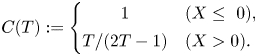 \begin{gather}C(T):=\left\{\begin{array}{@{}cl} 1 & (X\leq~0), \\ T/(2T-1) & (X>0). \end{array}\right. \end{gather}
We furthermore introduce  ${D(T)=1-C(T)}$. The upstream case ( ${X\leq ~0}$) is included in this interaction law for the sake of completeness and clarity. Downstream of the edge, it accounts for a subtle interplay of capillarity with inertia; the functions C and D plotted in figure 4 are consulted tacitly from here on. The pole of $C$ points to an interesting local increase of the capillary action for ${T\sim 1/2}$. The passage of $T$ over this threshold (where surface tension exactly compensates the streamwise momentum of the pressure-free base flow) is associated with an unbounded increase of $P$ and $H$ over $A$ and implies the onset of condensed interaction, which causes a breakdown of the existing flow description for the free jet. This requires the introduction of a streamwise scale relatively short as compared with the stretched interactive one and can be interpreted as choking of a capillary wave. A second critical value ${T=1}$ ( ${S=0}$) describes the cancelling of the counteracting effects of streamline curvature and capillarity on the transverse momentum transfer. Both are subsumed by $A''$ and, thus, actually originate in the viscous forcing of the LD. The absence of their net influence hampers the interaction pressure from becoming effective, where $H_-$ remains unspecified according to (2.14d), unless $A$ grows significantly to allow for a proper regularisation over a suitably shortened scale. Both exceptional situations are skated over below (§ 2.2.3) and still the subject of ongoing investigations.
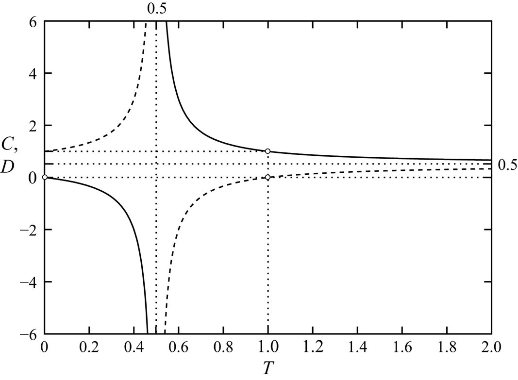
Figure 4. Plots of  $C(T)$ (solid) and $D(T)$ (dashed) by (2.14f) ( ${X>0}$) with their asymptote and poles (all dotted), fixed point and zeros (all as circles).
The rescaled shear stress exerted at the plate,  ${\varLambda (X):=\varPsi _{ZZ}(X,0)}$, plays a crucial role for the (unambiguous) formulation of the initial conditions (ICs) imposed at the plate edge ${X=0}$ by Reference Scheichl, Bowles and PasiasSBP18 for the detached flow, controlling its upstream influence on the plate-bounded flow in a unique manner. The detailed rationale underlying these deserves to be clarified in terms of the following three steps.
(i) The two original demands on the interaction mechanism were the simultaneous continuous approach of the overall pressure jump across the layer towards $-P_-$ and of $\varLambda$ towards zero in the limit ${X {\rightarrow 0}-}$, but only the first of these typical edge conditions can be met.
(ii) If
(2.14g)which is the case pursued here, the conditions the flow has to meet at the edge can then be formulated without resorting to the analysis of smaller regions enclosing the edge.\begin{equation} \epsilon^{12/7}\ll T<1\quad (S={-}1,\ T\neq~1/2), \end{equation}(iii) Then a least-degenerate flow description that allows for a smooth gradual transition from attachment to detachment of the flow quantities on smaller streamwise scales requires continuity of
$\varPsi$ and $A'$ above the edge.


The sought quantities  $\varPsi$ and $P$ satisfy the, with respect to $X$, first- and second-order equations (2.14a) and (2.14e). In turn, three ICs are required to continue marching over the edge,
 \begin{equation} \varPsi_0:=\varPsi(0+,Z)=\varPsi(0-,Z)\enspace (Z>0),\quad T[A'(0+)-A'(0-)]=0,\quad P(0)=P_- \end{equation}
(or, equivalently,  ${A''(0)=-SG}$). These complete the interaction problem (2.14) for the free jet. Here the flow profile at detachment $\varPsi (0-,Z)$ and $A'(0-)$ are taken as obtained by the preceding sweep of numerical marching towards the edge. It is stressed that $\varPsi$, $P$ behave regularly as ${X {\rightarrow 0}-}$. Moreover, these quantities are continuous across the edge except for the shear stress $\varPsi _{ZZ}$ on ${Z=0}$, owing to (2.14b).
We also recall the behaviour, inferred from (2.14a,b), for
 \begin{equation} Z{\rightarrow 0}\colon \varPsi\sim\left\{\begin{array}{@{}lc} \varLambda(X)Z^{2}/2+P'(X)Z^{3}/6+O(Z^{5}) & (X\leq~0), \\ {U_{s}}(X)Z+[P'+{U_{s}}{U_{s}}'](X)Z^{3}/6+O(Z^{5}) & (X>0). \end{array}\right. \end{equation}
Hence, the finite slip emerging along the lower free streamline,  ${U_{s}}$, supersedes the finite plate stress $\varLambda$ upstream of the edge. We note that (2.15) first implies that
 \begin{equation} \varPsi_0\sim\varLambda_0 Z^{2}/2+P'(0-)Z^{3}/6+O(Z^{5})\quad (Z{\rightarrow 0}),\quad \varLambda_0(G,T):=\varLambda(0-). \end{equation}
The apparent non-uniformity of (2.16a,b) for  ${X=0+}$ is the topic of § 3.2 below. The parameters $G$ and $P_-$, representing the freely chosen support pressure, enter the solution of the interaction problem only via (2.14h), i.e. $G$ in terms of the imposed momentum flux, and subsequent integration of $P'(X)$ found in the course of the marching procedure. The decoupled calculation of $H_-$ is finally provided by (2.14d). Eliminating $P$ with the aid of (2.14e) gives the alternative relation
 \begin{equation} H_-(X)=D(T)\left[A(X)-A(0-)-A'(0-)X+(G-P_-)SX^{2}/2\right], \end{equation}
i.e.  ${H_-(0)=H_-'(0)=0}$. Evidently, the support pressure behaves as a body force counteracting gravity.
2.2.3. Some important aspects
To achieve the last requirement in (2.14h), the interaction is initiated in the limit  ${X {\rightarrow -\infty }}$ by a controlled branching from the oncoming base flow, here maintained as the trivial solution ${\varPsi \equiv Z}$ for ${X\leq ~0}$ if ${G=P_-\geq ~0}$. Hence, the case ${G>P_-}$ requires branching of expansive type as scrutinised by Reference Scheichl, Bowles and PasiasSBP18 (where ${P_-=0}$ throughout) and the opposite one ${0\leq G< P_-}$ compressive branching (unconsidered so far). However, since $A''(X)$ is the streamline curvature in the interactive limit, it becomes evident from (2.14e) that the interactive feedback loop triggers stationary capillary waves iff ${SC>0}$. Here this implies ${0< T<1/2}$ or ${T>1}$; see the preceding studies by Bowles & Smith (Reference Bowles and Smith1992) and Reference Scheichl, Bowles and PasiasSBP18 and the preliminary presentation of these interactive undulations by Scheichl, Bowles & Pasias (Reference Scheichl, Bowles and Pasias2019). Their revealing linkage to unsteady linear capillary waves is given in Appendix B.
Moreover, Reference Scheichl, Bowles and PasiasSBP18 demonstrated how the phenomenon of stationary waves up- and downstream of the edge for  ${T>1}$ is associated with pre-detachment and severely violates the considerations (i)–(iii) and the notion of expansive branching. They finally disclosed non-uniqueness of the solutions due to an arbitrary phase shift far upstream, presumed fixed by an as yet missing further downstream condition. We are therefore still left with the two constraints (2.14g) in our consistent description of the flow continued downstream of the edge by dint of (2.14). The first states that not only $A(X)$ but also $A'(X)$ is continuous at ${X=0}$, so that we henceforth omit the signs in the arguments $0-$ and $0+$ of $A$, expressing one-sided limits. The second guarantees strictly forward interacting flow upstream of the edge, thus, ${\varLambda _0>0}$ in (2.16a,b). Since realistic values of $\tau$ and $J$ by (2.8) yields ${T\lesssim 10}$, assuming ${T<1}$ seems acceptable; see table 1 and the last comment in Appendix A.
However,  $A$ becomes discontinuous at the edge in the limit ${T {\rightarrow 0}}$ in (2.14e) and (2.14h), implying the absence of interaction ( ${P'\equiv 0}$) for ${X>0}$. Here the possibility of free interaction exists but the conditions at ${X=0}$ do not provoke it even upstream of the edge in the formal limit ${G-P_-=T=0}$. Then the classical Goldstein wake (Goldstein Reference Goldstein1930) is recovered immediately downstream as the trivial solution ${[\varPsi ,P]\equiv [Z^{2}/2,G]}$, representing the oncoming base flow, applies upstream of it.
3. Inviscid detachment at smaller scales
As emphasised in more detail below, the interactive flow structure leaves us with a still singular transition from no- to free-slip. It therefore initiates its own breakdown on scales much smaller than the interactive ones. The bottom line of the subsequent analysis is that of demonstrating self-consistency of the interaction theory and a required smooth behaviour of all flow quantities at the edge demands a thorough analysis of the smaller scales (figure 3b–d). This will also highlight the strikingly different characteristics of the gross break-away of the film, i.e. the formation of a free streamline at the solid wall, in the present situation and (well-understood) steady internal separation. In the first, the flow quantities appear to undergo weak algebraic singularities, whereas in the second their behaviour is well known to be regular at separation (Goldstein Reference Goldstein1930).
3.1. The influence of capillarity
To advance further in completing the description of flow detachment, it proves useful to first summarise the analysis in Reference Scheichl, Bowles and PasiasSBP18 of the interplay of surface tension and the Goldstein wake in the non-interactive limit  ${x {\rightarrow 0}+}$. Here the latter exerts a displacement $-a x^{1/3}$ with some constant ${a>0}$ ( ${a\simeq ~1.0079}$ if $\psi _0$ is given by Watson's profile on top of the wake), so that ${\psi \sim \psi _0(z)+a x^{1/3}\psi _0'(z)+O(x^{2/3})}$. Accordingly, (2.3c), (2.6a,b) and the Prandtl shift in (2.11) yield ${[h_-,h_+]\sim [a_-,a_- -a]x^{1/3}+O(x^{2/3})}$ with some sought constant $a_-$, and (2.3b) states that ${p_y+g\sim \epsilon ^{2}(a-a_-)(x^{1/3})''\psi _0'^{2}(y)}$. By integration across the unperturbed layer, from ${y=0}$ to ${y=h_0}$, we finally obtain from (2.3e) the limiting overall capillary pressure jump in the form ${(a-a_-)x^{1/3}\sim -T(h_- +h_+)}$, i.e. ${T(2a_- -a)=a_- -a}$. This implies ${[h_-,h_+]\sim a x^{1/3}[D,-C](T)}$, cf. (2.14f). One draws the important conclusion that $h_-(x)$ is required to be regularised on the interactive and again on smaller scales even for ${T\geq ~0}$, whereas ${h_+'(x)\ (>0)}$ remains continuous at ${x=0}$ for ${T=0}$ as the inverse Prandtl shift produces additional irregular terms in the core region for ${x {\rightarrow 0}+}$ and a cuspidal distortion of $h_+(x)$ exists for ${T>0}$ only. Even then, however, the complete regularisation of $h_+(x)$ is left to higher orders over the interactive $x$-scale, where it is accomplished by the introduction of a thin shear layer adjacent to the upper free surface in order to satisfy (2.3e) (cf. Reference Scheichl, Bowles and PasiasSBP18, § 3.3.4).
It is noteworthy to highlight the difference to the related classical situation of the gravity- and capillarity-free axisymmetric flow exiting a pipe (Tillett Reference Tillett1968). There symmetry cancels the leading-order displacement in the core region but the vorticity gradient of the Hagen–Poiseuille profile (as opposed to streamline curvature) provokes an higher-order displacement and vertical pressure, requiring a regularisation similar to that discussed below.
Keeping in mind the above preliminary considerations operating for arbitrarily small values of  $T$, we consider the precise regularisation of $h_\pm$ for finite values of $T$. To this end, we first reappraise the interaction under the first of the restrictions (2.14g). The details of the detached flow in the close vicinity of the edge as reported by Reference Scheichl, Bowles and PasiasSBP18 provide an insight into how the full interactive structure is recovered for ${\epsilon ^{9/14}\ll X=O(T^{3/8})}$. In general, the so-called near-near wake, replacing the pressure-free Goldstein near wake, emerges as a subregion split off the main portion of the LD to absorb the nonlinearity of the interaction immediately downstream of the trailing edge. Most importantly, it dictates the onset of free slip according to (2.14b).
3.2. Extended Hakkinen–Rott wake
As the second of the ICs (2.14h) requires  ${A-A(0)=O(X)}$ ( ${X {\rightarrow 0}}$), the near-near wake must suppress any larger contribution to $A$, hence transferred passively through the core of the LD. As a consequence of this leading-order analysis, this wake itself then provides an example of condensed interaction through an interesting, capillarity-controlled specification of the pressure-driven Hakkinen–Rott wake (HRW, Hakkinen & Rott Reference Hakkinen and Rott1965): $P$ vanishes as ${X {\rightarrow 0}}$ in an irregular manner such that the wake exerts zero displacement. Since the canonical pressure gradient in the HRW turns out to be adverse, the capillary pressure jump (2.14d) enforces the lower free streamline to be convex immediately downstream of detachment in ${X=0}$ (where it is curvature-free). It thus bends vertically upwards as $X$ grows. The strong pressure rise provokes an enhanced streamline curvature, and this in turn the aforementioned breakdown and required smoothing of the interaction theory for sufficiently small values of $X$, as already indicated in figure 1. In the LD this behaviour may be fully understood if one considers only the behaviour of the leading-order quantities $\varPsi$ and $P$, i.e. under the neglect of the vertical pressure variations.
The flow profile in the HRW matches that at detachment at its upper extent in its limiting form given by (2.16a,b). As a result, the self-preserving flow in the HRW discerned for  ${X {\rightarrow 0}+}$ resolves the non-uniformity of (2.16a,b). It is expressed as the inner limit
 \begin{equation} \left[\frac{\varPsi}{\varLambda_0^{1/3}X^{2/3}},\frac{{\rm \Delta} P}{\varLambda_0^{4/3}X^{2/3}}, \frac{H_-}{\varLambda_0^{4/3}X^{8/3}}\right]\sim \left[{f_{HR}}(\eta),{p_{{HR}}},\frac{9{p_{{HR}}}}{40}\frac{1-T}{T}\right],\quad \eta:=\frac{\varLambda_0^{1/3}Z}{X^{1/3}}, \end{equation}
with the pressure difference  ${\rm \Delta} P$ introduced in (2.14d). Here the universal wake function ${f_{HR}}$ satisfying ${{f_{HR}}'^{2}-2{f_{HR}}{f_{HR}}''=-2{p_{{HR}}}+3{f_{HR}}'''}$, ${{f_{HR}}(0)={f_{HR}}''(0)}$ and the matching condition ${{f_{HR}}'\sim \eta +\text {TST}}$ as ${\eta {\rightarrow \infty }}$ is recalled. The absence of a constant displacement term determines the eigenvalue ${p_{{HR}}}$ and prevents $A$ from being of $O(X^{1/3})$ as ${X {\rightarrow 0}+}$ and enforces continuity of $A'$ as required by (2.14h). Our refined numerical study yields ${{p_{{HR}}}\simeq ~0.61334}$ and a rescaled free slip ${{f_{HR}}'(0)\simeq ~0.89915}$ obtained with ${ax(\eta )=50}$ (cf. Hakkinen & Rott (Reference Hakkinen and Rott1965), Reference Scheichl, Bowles and PasiasSBP18). This gives ${{U_{s}}\sim {f_{HR}}'(0)X^{1/3}}$ ( ${X {\rightarrow 0}+}$) in (2.15) when rewritten in the limit ${\eta {\rightarrow 0}}$.
Next, we propose the regular/singular upstream/downstream behaviour including higher orders
 \begin{equation} {\rm \Delta} P\sim\left\{\begin{array}{@{}ll} P'(0-)X+P''(0-)X^{2}/2+O(X^{3}) & (X{\rightarrow 0}-), \\ {p_{{HR}}}\varLambda_0^{4/3}X^{2/3}+c_1 X\ln{X}+c_2 X+O\left(X^{4/3}(\ln{X})^{2}\right) & (X{\rightarrow 0}+) \end{array}\right. \end{equation}
with the logarithmic variations and the constants  $c_1,$ $c_2$ to be determined through a higher-order analysis of the HRW. Accordingly, from (2.14e–g) or (2.17),
 \begin{equation} A-A(0)\sim A'(0)X+(G-P_-)\frac{X^{2}}{2}+\left\{\begin{array}{@{}l} O(X^{3}), \\ -\dfrac{9{p_{{HR}}}\varLambda_0^{4/3}}{40C(T)}X^{8/3}+O(X^{3}\ln{X}). \end{array}\right. \end{equation}
Our expectation of a more nonlinear theory superseding the current one when  $T$ crosses $1/2$, at the pole of $C(T)$, complies with the sign change of the singular contribution to $A$ provided by the HRW. That weak downstream irregularity is also transferred to $H_+$, cf. (2.11), as
 \begin{equation} H_+{\sim}{-}A(0)-A'(0)X-(G-P_-)\frac{X^{2}}{2}+\left\{\begin{array}{@{}l} O(X^{3}), \\ \dfrac{9{p_{{HR}}}\varLambda_0^{4/3}}{40}X^{8/3}+O(X^{3}\ln{X}). \end{array}\right. \end{equation}
By the expansive type of interaction for  ${S=-1}$, $A(X)$ bends convexly but $P(X)$ concavely throughout (Reference Scheichl, Bowles and PasiasSBP18). That is, we can expect here ${A(0)>0}$, ${A'(0)>0}$, but ${P'(0-)<0}$.
One infers from (2.14c) that the  $i$th ( ${i=1,2,\ldots }$) contribution to the expansion for ${\varPsi -\varPsi _0}$ as ${X {\rightarrow 0}}$ attains the form ${d_i(X)Z+e_i(X)+\text {TST}}$ as ${Z {\rightarrow \infty }}$ where the series of gauge functions $d_i$ and $e_i$ are determined by the expansions (3.2) and (3.3) and add up to respectively ${A(X)-A(0)}$ and ${[A(X)^{2}-A(0)^{2}]/2+P(X)}$. Typically, ${e_i(X)\varPsi _0'(Z)}$ are the eigensolutions of the linearised convective operator in (2.14a). By matching $\varPsi$ in the LD and the MD, the solution of the inviscid version of (2.14a) indeed yields the accordingly refined form of the expansion for $\varPsi$ given by Reference Scheichl, Bowles and PasiasSBP18 (as (3.2), correctly including the logarithmic terms). So, with ${\rm \Delta} P$ expanded as in (3.2), we have for
 \begin{equation} X{\rightarrow 0}\pm\colon \varPsi-\varPsi_0-A'(0)X\,\varPsi_0'(Z)\sim{\rm \Delta} P\varPsi_0'\int_Z^{\infty} \frac{\text{d} t}{\psi_0'^{2}(t)}\sim {\rm \Delta} P\left\{\begin{array}{@{}ll} 1 & (Z{\rightarrow\infty}), \\ 1/\varLambda_0 & (Z{\rightarrow 0}). \end{array}\right. \end{equation}
A detailed higher-order analysis of the HRW demonstrates self-consistency of the interactive asymptotic structure for  ${X {\rightarrow 0}}$. Amongst other aspects, it fixes the dependence of the coefficients $c_1$, $c_2$ in (3.2) on the parameters characterising the LD flow in the limit ${X {\rightarrow 0}-}$. Here we refer the interested reader to supplement A.
The breakdown and so a required regularisation of the interactive flow structure for sufficiently small values of  $X$ is due to an unbounded vertical flow component and vertical pressure gradient evoked by the $O(X^{2/3})$-term in (3.2) and (3.5) and the associated $O(X^{3/8})$-term in (3.3). As a crucial observation, even then the pressure gradient in the HRW stays imposed by the flow on its top and must vary such that a potential singular displacement varying with $X^{1/3}$ is suppressed. Since the self-similar structure of the HRW already absorbs this type of condensed interaction and is recovered at its origin closer to the trailing edge, (3.1a,b) prevails even over an $x$-scale much smaller than the interactive one. As a result, $h_-$ is still given by (3.1a,b) in § 3.3 below.
3.3. Outer and inner Euler regions
We here consider the two nested square outer and inner vortical-flow regions (when measured by the equally scaled global horizontal and vertical coordinates  $x$ and $\epsilon y$) that supersede locally the MD (outer) and the LD (inner) but where ${\psi \sim \psi _0}$ and ${\varPsi \sim \varPsi _0}$ still govern the flow at leading order. The associated linearised Euler stages (outer and inner RS) account for the small-scale upstream influence, within that on the interactive scale, and serve to regularise the singular behaviour predicted in § 3.2; most importantly, $h_+(x)$ by virtue of $H_+$ (outer). It is furthermore noted that the aforementioned large- $Z$ representation of the expansion (3.5) accompanies a passive re-ordering of its hierarchy, so as to match the small- $X$ limit of (2.11) provided by (3.3). Accordingly, the last expansion enforces a contribution of $O(X^{3/8})$ to (3.5) and this in turn a pressure-driven one of $O(X^{2/3})$ to the non-interactive disturbance of $O(\epsilon ^{4/7})$ in (2.11).
3.3.1. Preliminaries
Introductory considerations lay the foundation for the outer and inner mechanisms for the further regularisation of the HRW, as follows.
(a) The interactive
$u$- and $p$-variations, on account of streamline curvature via the vertical pressure variation in (2.3b), are of respectively $O(\epsilon ^{2/7}X^{8/3})$ and $O(\epsilon ^{4/7}X^{2/3})$ as ${X {\rightarrow 0}+}$. They and the non-interactive $u$-perturbation in (2.11), provoked by the streamwise pressure variation through (2.3a), all become of $O(\epsilon ^{2/3})$ in the outer RS (§ 3.3.2) where, cf. (2.13a–c),
(3.6)\begin{equation} \bar{X}:= x/\epsilon=X/(l\epsilon^{1/7})=O(1). \end{equation}(b) Conversely,
$v$ of $O(\epsilon ^{5/7}X^{-1/3})$ grows significantly to become comparable in size to the $u$-perturbation of ${\epsilon ^{2/7}X^{2/3}}$ across most of the LD for ${X=O(\epsilon ^{3/7})}$, i.e. in the inner RS (§ 3.3.5) where
(3.7)However, as\begin{equation} \hat{X}:= x/(m\epsilon^{9/7})=X/(lm\,\epsilon^{3/7})=O(1). \end{equation}$p$ and $\psi$ of $O(\epsilon ^{2/3})$ at its base and downstream of the edge are still prescribed by the HRW, the inner RS cannot regularise the associated singularity expressed by (3.2) and (3.5). Therefore, the analysis of the inner RS is of only subordinate importance compared with that of the outer one.(c) A quick justification of the expansions of the flow quantities below for both square regions relies on the relevant inviscid-flow approximation of the elliptic vorticity transport equation, obtained from elimination of the pressure in (2.3a,b),
(3.8)To express\begin{equation} \psi_{yy}+\epsilon^{2}\psi_{xx}\sim{-}\varOmega(\psi):=\psi_0''\left(\psi_0^{{-}1}(\psi)\right). \end{equation}$\varOmega$ as the vorticity conserved along the streamlines, we use $\psi _0^{-1}$ to symbolise the inversion of the corresponding leading-order relationship ${\psi \sim \psi _0(y)}$. As a consequence, the contributions to those expansions are triggered by the vorticity imposed by the surrounding interactive flow and, in addition, the vorticity produced by the HRW and entering via non-trivial matching or BCs. These are provided by (3.5) with (3.2) for ${Z {\rightarrow \infty }}$ at the base of the outer RS and on top of the inner RS and by matching (3.5) for ${Z {\rightarrow 0}}$ and (3.1a,b) at the base of the latter. Consequently, eigensolutions of the linearised operator in (3.8) are absent.


It is noteworthy that Stewartson (Reference Stewartson1968) discovered the generic advent of a linearised Euler or Rayleigh stage when he solved the (non-rigorous) Oseen approximation of the NS problem governing the unconfined flow in a small region around a trailing edge, and prior to the far-reaching rigorous appreciation of viscous–inviscid interaction on larger scales (Stewartson Reference Stewartson1969; Messiter Reference Messiter1970).
3.3.2. Outer Rayleigh stage: main deck
In the outer square region,  $p$ is, as in the surrounding MD, of $O(\epsilon ^{4/7})$, and the viscous terms in (2.3a,b) become formally of $O(\epsilon )$ as all remaining ones can be scaled to $O(1)$. Following the comments (a) and (c) above, substitution of (3.3) into (2.11) suggests, in this domain, the expansion ${\psi \sim \psi _0(y)+\epsilon ^{2/7}\psi _1(y)+\epsilon ^{3/7}\psi _2(y)+\epsilon ^{4/7}\psi _3(y)+O(\epsilon ^{4/6})}$. The sought functions $\psi _{1,2,3}$ satisfy the hierarchy of Rayleigh equations
 \begin{equation} ({\partial}_{yy}+{\partial}_{\bar{X}\bar{X}}-\psi_0'''/\psi_0')\psi_{1,2}=0,\quad ({\partial}_{yy}+{\partial}_{\bar{X}\bar{X}}-\psi_0'''/\psi_0')\psi_3=\psi_1^{2}(\psi_0'''/\psi_0')'/(2\psi_0') \end{equation}
resulting from expanding (3.8). According to the considerations following (3.8) and the regularity of (2.11) upstream of the trailing edge,  $\psi _{1,2}$ consist just of the pressure-free disturbances given by the Taylor series of $A(X)$ up to second order, where ${A''(0-)=G-P_-}$ from (2.14e) subject to (2.14h). This and the inhomogeneity in the last equation in (3.9a,b), caused by the inertia-based nonlinearities, require an additional $y$-dependent component of $\psi _3$.
Specifying these findings gives
 \begin{align} \left[\psi,h_+\right] &\sim \left[\psi_0(y),h_0\right] \nonumber\\ &\quad + m\left[\epsilon^{2/7}A(0)+\epsilon^{3/7}A'(0)l\bar{X}+\epsilon^{4/7}(G-P_-)(l\bar{X})^{2}/2\right] \left[\psi_0'(y),-1\right] \nonumber\\ &\quad + \epsilon^{4/7}m\left[\psi_\ast(y),-\psi_\ast(h_0)/u_0^{+}\right]+ \epsilon^{4/6}\left[\bar{\varPsi}(\bar{X},y),\bar{H}(\bar{X})\right]+O(\epsilon^{5/7}). \end{align}
Hence,  $\psi _\ast$ denotes the limiting value of the corresponding $O(\epsilon ^{4/7})$-contribution to the expansion (2.11) of $\psi$ in ${X=0}$. That quantity satisfies $\psi _\ast ''-(\psi _0'''/\psi _0')\psi _\ast =(\psi _0'''/\psi _0')'A(0)^{2}/2-A''(0-)\psi _0 '$, where the last inhomogeneity reflects the action of the streamwise pressure gradient. We furthermore expand
 \begin{equation} p\sim\epsilon^{4/7}m l^{2}\left[(G-P_-)\int_0^{y}\psi_0'^{2}(t)\,\text{d} t- M\left(\frac{Gy}{h_0}-P_-\right)\right] +\epsilon^{4/6}\bar{P}(\bar{X},y)+O(\epsilon^{5/7}). \end{equation}
The  $X$-independent leading-order term in (3.11) is again just the dominant contribution to $p$ in the MD up- and downstream of the trailing edge (cf. Reference Scheichl, Bowles and PasiasSBP18) evaluated at ${X=0}$ and rewritten with the aid of (2.9a–c). Here the irregular terms in (3.3) play no role. It follows from inserting (3.10) into (2.3b) and integrating its thereby reduced form ${p_y\sim \epsilon ^{4/7}m l^{2}\psi _0'^{2} -g}$ subject to ${p\sim p_-}$ as ${y {\rightarrow 0}}$, to match $p$ in the LD. Moreover, (3.10) fulfils (2.3c) supplemented with (2.6a,b) and, together with (3.11), complies with the capillary pressure jump at ${y=h_+}$ in (2.3e) up to $O(\epsilon ^{4/7})$ for ${\bar {X}=O(1)}$. The $O(\epsilon ^{4/6})$-contributions to (3.10), (3.11) serve to regularise the flow quantities in the MD. As the subsequent analysis of $\bar {\varPsi }$, $\bar {H}$, $\bar {P}$ makes clear, those expansions do not contain lower-order eigenfunctions having sufficiently strong decay for ${|\bar {X}| {\rightarrow \infty }}$, consistent with (2.11).
Invoking the inverse Prandtl shift in (3.10) gives  ${\psi _0(y)\sim \psi _0(z)+h_-\psi _0'(z)}$ for ${h_-=O(\epsilon ^{2/3})}$, see (3.4), and brings to mind matching $\psi$ up to $O(\epsilon ^{2/3})$ in (2.11) and also in the LD, according to (3.5) and (3.2). Furthermore, $\bar {\varPsi }$, $\bar {P}$ are seen to satisfy the linearised Euler equations
 \begin{equation} \psi_0''\bar{\varPsi}_{\bar{X}}-\psi_0'\bar{\varPsi}_{y\bar{X}}=\bar{P}_{\bar{X}},\quad \psi_0'\bar{\varPsi}_{\bar{X}\bar{X}}=\bar{P}_{y}. \end{equation}
To separate the influence of the shear stress at detachment,  $\varLambda _0$, effective in the LD and of a potential $\bar {X}$-independent contribution to $\bar {\varPsi }$ arising from integration of (3.12a,b) (i.e. no $O(\epsilon ^{2/3})$-contribution to $\varOmega$, cf. (3.8), in the surrounding MD), we advantageously consider the scaled vertical flow perturbation
 \begin{equation} \bar{V}:={-}\bar{\varPsi}_{\bar{X}}/\bar{\varLambda},\quad \bar{\varLambda}:=~2\,{p_{{HR}}}\,\lambda^{1/3}\varLambda_0^{4/3}/3. \end{equation}
Equations (3.12a,b) yield the Rayleigh equation governing  $\bar {V}$ in accordance with (3.9a,b), i.e.
 \begin{equation} ({\partial}_{yy}+{\partial}_{\bar{X}\bar{X}}-\psi_0'''/\psi_0')\bar{V}=0. \end{equation}
Matching  $\psi$ and $p$ in the outer RS and the LD with the support of (2.12) and $m$,
$m$,  $l$ given by (2.11), (2.13a–c) requires for
 \begin{equation} y=0\colon\ \bar{V}={-}\theta(\bar{X})\bar{X}^{{-}1/3}.\end{equation}
Furthermore, expanding (2.3c) and (2.3e) gives
 \begin{equation} \bar{H}={-}\bar{\varPsi}(\bar{X},h_0)/u_0^{+} \end{equation}
and  ${\bar {P}(\bar {X},h_0)=-\tau \bar {H}''(\bar {X})}$, respectively. By the same token, inspection of (3.12a,b) with the help of (2.6a,b), (2.9a–c) and (3.14c) gives for
 \begin{equation} y=h_0\colon\ u_0^{+}{}^{2}\,\bar{V}_{y}={-}TJ\bar{V}_{\bar{X}\bar{X}}, \end{equation}
i.e. the explicit dependence of  $\bar {V}$ on $T$.
$T$.
Also, matching (3.10), (3.11) with (2.11) and  $p$ in the MD subject to (3.3) and (3.2) yields ${\bar {\varPsi } {\rightarrow 0}}$ and ${\bar {P} {\rightarrow 0}}$, thus, ${\bar {V} {\rightarrow 0}}$ and ${\bar {H} {\rightarrow 0}}$ by (3.14c), as ${\bar {X} {\rightarrow -\infty }}$. In contrast, ${\epsilon ^{2/3}\bar {\varPsi }}$ for ${\bar {X}\gg 1}$ must match the dominant singular behaviour of ${\psi -\psi _0\sim \epsilon ^{2/7}m(A-H_-)(X)\psi _0'(y)}$ for ${X\ll 1}$ as inferred from (2.11). The expansions (3.1a,b), (3.3) and ${\psi -\psi _0\sim -(9\,{p_{{HR}}}/40)\epsilon ^{2/3}m\varLambda _0^{4/3}(l\bar {X})^{8/3}}$ imply ${\bar {V}/\psi _0'(y)\sim 9\lambda \bar {X}^{5/3}/(10M)+O(\bar {X}^{-1/3})}$ ( ${\bar {X} {\rightarrow \infty }}$). Likewise, (3.13a,b) and (3.14c) give ${\bar {H}/\bar {\varLambda }\sim 27\lambda \bar {X}^{8/3}/(80M)+O(\bar {X}^{2/3})}$. This proves consistent with the interplay of the two free surfaces in § 3.2.
It is illuminating to demonstrate that the up- and downstream asymptotes are already intrinsic to the problem (3.14) governing  $\bar {\varPsi }$ and $\bar {H}$. To this end, we consider the weakest admissible, i.e. first algebraic, decays of $\bar {V}$ for ${\bar {X}\to \pm \infty }$ with unknown dominant corresponding rates $\bar {a}_\pm (\bar {X})$, say. We obtain from (3.14a,b), using ${( {\partial }_{yy}-\psi _0'''/\psi _0')\bar {V}\equiv (\psi _0'\bar {V}_{y}-\psi _0''\bar {V})_y/\psi _0'}$ and standard methods and (2.5a,b), the long-wave approximation of $\bar {V}$,
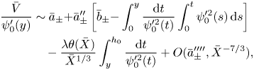 \begin{align} \frac{\bar{V}}{\psi_0'(y)} &\sim\bar{a}_\pm{+}\bar{a}_\pm'' \left[\bar{b}_\pm{-}\int_0^{y}\frac{\text{d} t}{\psi_0'^{2}(t)}\int_0^{t}\psi_0'^{2}(s)\,\text{d} s\right] \nonumber\\ &\quad -\frac{\lambda\theta(\bar{X})}{\bar{X}^{1/3}}\int_y^{h_0}\frac{\text{d} t}{\psi_0'^{2}(t)}+ O(\bar{a}_\pm'''',\bar{X}^{{-}7/3}), \end{align}
where  $\bar {a}_\pm$ and the constants $\bar {b}_\pm$ are determined by solvability conditions of the inhomogeneous problems governing the $O(\bar {a}_\pm '')$-term and the $O(\bar {a}_\pm '''')$-term, respectively. The small- $y$ behaviour of $\psi _0$ in (2.5a,b) grants a corresponding regularity of the right-hand side of (3.15). Substitution of (3.15) into (3.14d) using (2.5a,b) and (2.6a,b) gives, after division by $u_0^{+}$, the solvability relation ${\bar {a}_\pm ''J-\lambda \theta (\bar {X})\bar {X}^{-1/3}\sim \bar {a}_\pm ''\tau }$. In the upstream case this statement can only be met in the limit ${T\to 1-}$; cf. (2.9a–c). Consequently, ${\bar {a}_-\equiv 0}$, ${\bar {b}_-=0}$, and the upstream decay is indeed exponential, although the limit of an undamped (neutral or harmonic) oscillation may also be taken into consideration and an unbounded increase of $\bar {V}$ is expected for ${T\to 1-}$. In contrast,
 \begin{equation} \bar{a}_+{=}9\lambda\bar{X}^{5/3}/[10 J(1-T)] \end{equation}
confirms the aforementioned leading-order asymptote involving  $M$ defined in (2.9a–c). This shows that matching (3.10) and (2.11) requires ${T<1}$.
As a further result, (3.12a,b) yields
 \begin{equation} \bar{P}=\psi_0''\bar{\varPsi}-\psi_0'\bar{\varPsi}_{y}, \end{equation}
and  ${\bar {P}\sim 3\lambda \bar {\varLambda }\bar {X}^{2/3}/2}$ ( ${\bar {X} {\rightarrow \infty }}$) provides the match of $p$ in the MD, according to (3.2), (3.5) and (3.14b). This and ${\bar {P}(\bar {X},0)=3\lambda \bar {\varLambda }\,\theta (\bar {X})\bar {X}^{2/3}/2}$ make evident how $\bar {\varPsi }$ and $\bar {P}$ resort to these behaviours originating in the HRW and why the inner RS is required to complete the regularisation closer to the trailing edge. Since the coefficient $\psi _0'''/\psi _0'$ in (3.14a) becomes, from (2.5a,b), ${\omega y}$ for ${y\ll 1}$, (3.14b) allows $\bar {V}$ to attain an undesired potential-flow pole in the origin, as described by the singular eigensolutions of the Laplacian ${r^{-N}\sin (N\vartheta )}$, where
 \begin{equation} r:=\sqrt{\smash[b]{\bar{X}^{2}+y^{2}}}{\rightarrow 0},\quad 0\leq\vartheta:=\arctan(y/\bar{X})\leq{\rm \pi} \end{equation}
and  ${N>0}$ is some integer (cf. Scheichl Reference Scheichl2014). Its occurrence has to be avoided in the further treatment of (3.14). Rather, (3.14b) and the vorticity term provoke a weaker singularity as one readily finds that
 \begin{equation} \bar{V}\sim\bar{V}_{0}+\bar{c}_1 y+\bar{c}_2 xy+O(r^{8/3})\quad (r{\rightarrow 0}),\quad \bar{V}_{0}:=~2 r^{{-}1/3}\sin({\rm \pi}/3-\vartheta/3)/\sqrt{\smash[b]{3}}, \end{equation}
and (3.17) recovers the pressure induced by the HRW as  ${\bar {P}=O(r^{2/3})}$. The first three contributions to $\bar {V}$ in (3.19a,b) are of potential-flow type, and the coefficients $\bar {c}_{1,2}$ of the homogeneous ones are determined by the overall solution for $\bar {V}$. The (lengthy expression of the) $O(r^{8/3})$-term in (3.19a,b) solves the Poisson problem to which (3.14a) reduces, with ${\psi _0'''\bar {V}/\psi _0'\sim \omega y\bar {V}_{0}}$ forming the inhomogeneity. The singularity described by $\bar {V}_{0}$ is pivotal in § 3.3.5 where it comes to its regularisation by the inner RS.
For what follows, we introduce the Fourier transform of a function  $f(\bar {X},y)$ for complex wavenumbers $k$,
$k$,
 \begin{equation} \phi\{\,f\}(k,y)=\frac{1}{2{\rm \pi}}\int_{-\infty}^{\infty} f(\bar{X},y)\,{\textrm{e}}^{-\text{i} k\bar{X}}\,\text{d}\bar{X}. \end{equation}
We first assume that  $\bar {V}$ decays exponentially far upstream. Since it grows with $O(\bar {X}^{5/3})$ as $\bar {X}$ becomes large, (3.20) defines $\phi \{\bar {V}\}$ first in the open strip ${-u_1(T)< \mbox{Im}\,k<0}$, where ${-u_1}$ denotes the imaginary coordinate of the pole in the lower half-plane ${\mbox{Im}\,k\leq ~0}$ lying closest to the real axis. The analytic continuation of $\bar {V}$ into the entire $k$-plane excluding the locations of singularities is provided by the convenient decomposition
 \begin{equation} \phi\{\bar{V}\}(k,y)=\mathcal{B}(k)\mathcal{V}(k,y),\quad \mathcal{B}(k):=\phi\left\{\theta(\bar{X})\bar{X}^{{-}1/3}\right\}(k)= 1/\left[\sqrt{\smash[b]{3}}\,\mathrm{\Gamma}\left({\tfrac{1}{3}}\right)(\text{i} k)^{2/3}\right]. \end{equation}
The last expression is understood in connection with a branch cut along the positive imaginary  $k$-axis. Absorbing (3.14b) and accommodating the non-integer growth with $\bar {X}$ in (3.16), it captures the influence of the HRW and gives a non-trivial $\bar {V}$. Poles of $\mathcal {V}$ on the real $k$-axis allow for relaxing the original assumption of exponential decay by the inclusion of harmonic modes surviving far upstream. From (3.14) we deduce the Rayleigh equation
 \begin{equation} ({\partial}_{yy}-k^{2}-\psi_0'''/\psi_0')\mathcal{V}=0 \end{equation}
subject to the then inhomogeneous lower and the homogeneous upper BC,
 \begin{gather} y=0\colon\enspace \mathcal{V}={-}1, \end{gather}
 \begin{gather}y=h_0\colon\enspace \psi_0'^{2}\mathcal{V}_y=T J k^{2}\mathcal{V}; \end{gather}
cf. (2.5a,b). The solution of the two-point boundary value problem (3.22), parametrised by  $k$, facilitates the semi-analytical inversion of (3.20) so as to determine $\bar {V}$, parametrised by $\psi _0(y)$ and $T$, in an elegant manner, avoiding the abovementioned Laplacian eigensolutions; all the more, as our focus lies on $\bar {H}(\bar {X})$ given by (3.14c). For the numerical implementation of (3.22), we recall that $\psi _0$ is typically specified by Watson's (Reference Watson1964) flow profile. In turn, the properties (2.6a,b), (2.7) and the closed form of $\psi _0$ in Scheichl & Kluwick (Reference Scheichl and Kluwick2019) and the values for ${J=\lambda }$ and $u_0^{+}$ given by (2.8) are employed. Detailing the properties of (3.22), especially the behaviours of $\mathcal {V}$ for ${k {\rightarrow 0}}$ and ${|\mbox{Re}\,k| {\rightarrow \infty }}$ and the analysis of its poles, which select the discrete spectrum of $\bar {V}$ out of the continuous one (and where (3.22) does not have a solution but its homogeneous form does), is relegated to supplement B. These findings enable the representation of $\bar {V}$ in a most efficient manner as envisaged next.
The poles of  $\mathcal {V}$ lie symmetrically with respect to both the real and the imaginary $k$-axes. There are a double pole at ${k=0}$, exactly two real simple poles where ${k=\pm k_u(T)}$ with ${k_u>0}$ (§ B.1) and an infinite number of simple poles lying on ${k=\pm \text {i}u_i(T)}$ ( ${i=1,2,\ldots }$) with ${u_i>0}$ (§ B.3). Since ${\mathcal{V}(-k,y)\equiv\mathcal {V}(k,y)}$, ${{\textrm {Res}}_{k=-k_u}(\mathcal{V})=-{\textrm {Res}}_{k=k_u}(\mathcal{V})}$ and real, and ${{\textrm {Res}}_{k=-\text {i}u_i}(\mathcal{V})={\textrm {Res}}_{k=\text {i}u_i}(\mathcal{V})}$ and imaginary. We then have
 \begin{equation} \left[\bar{V},\frac{\bar{\varPsi}}{\bar{\varLambda}}\right](\bar{X},y)=\int_\mathcal{C} \mathcal{B}(k)\mathcal{V}(k,y)\,{\textrm{e}}^{\text{i} k\bar{X}} \left[1,\frac{\text{i}}{k}\right]\text{d} k, \end{equation}
where all possible paths of integration  $\mathcal {C}$ stretch from ${\mbox{Re}\,k=-\infty }$ to ${\mbox{Re}\,k=+\infty }$ and originate from one another through a continuous deformation as they divide the $k$-plane in two portions: the origin and all poles ${k=\text {i}u_i(T)}$ lie in the upper and all poles ${k=-\text {i}u_i(T)}$ in the lower part. We furthermore anticipate that both real poles are located either in the upper or the lower part to guarantee $\bar {V}$ being real. Indeed, as will be argued below to render $\bar {V}$ unique, $\mathcal {C}$ must bypass both real poles such that they lie in the lower part. This situation is sketched in figure 5 with the path $\mathcal {C}$ specified for the numerical calculation of $\bar {H}(\bar {X})$ by means of (3.23) and (3.14c) for ${\bar {X}\geq ~0}$. There the branch cut prevents a more efficient treatment of (3.23) using Cauchy's residue formula: to avoid accuracy issues associated with complex integration, we specified $\mathcal {C}$ to follow the real axis apart from small squares of lengths $2\varepsilon$ with the midpoints ${k=\pm k_u}$ and of length $\varepsilon$ with the midpoint in the origin. Consistency of the results is confirmed for values of $\varepsilon$ ranging from 0.1 to 0.3. On the other hand, applying Cauchy's residue theorem to (3.23) yields with (3.21a,b), the fact that ${{\textrm {Res}}_{k=-k_u}(\mathcal{V})=-{\textrm {Res}}_{k=k_u}(\mathcal{V})}$ and Euler's reflection formula after some algebra
 \begin{equation} \frac{\bar{\varPsi}}{\mathrm{\Gamma}\left(\tfrac{2}{3}\right)\bar{\varLambda}}=2{\textrm{Res}}_{k=k_u}(\mathcal{V}) \frac{\cos(k_u\bar{X}-{\rm \pi}/3)}{k_u^{5/3}}+ \text{i}\sum_{i=1}^{\infty}{\textrm{Res}}_{k={-}\text{i}\mu_i}(\mathcal{V}) \frac{\exp(\mu_i\bar{X})}{\mu_i^{5/3}}\quad (\bar{X}\leq~0) \end{equation}
(cf. Tillett Reference Tillett1968). This series of residues converges (uniformly) for any  ${\bar {X}<0}$. The full evaluation of (3.23) and smoothness of $\bar {\varPsi }$ for ${y>0}$ in ${\bar {X}=0}$ confirms that (3.24) holds even there although the decay of the exponentials has disappeared.
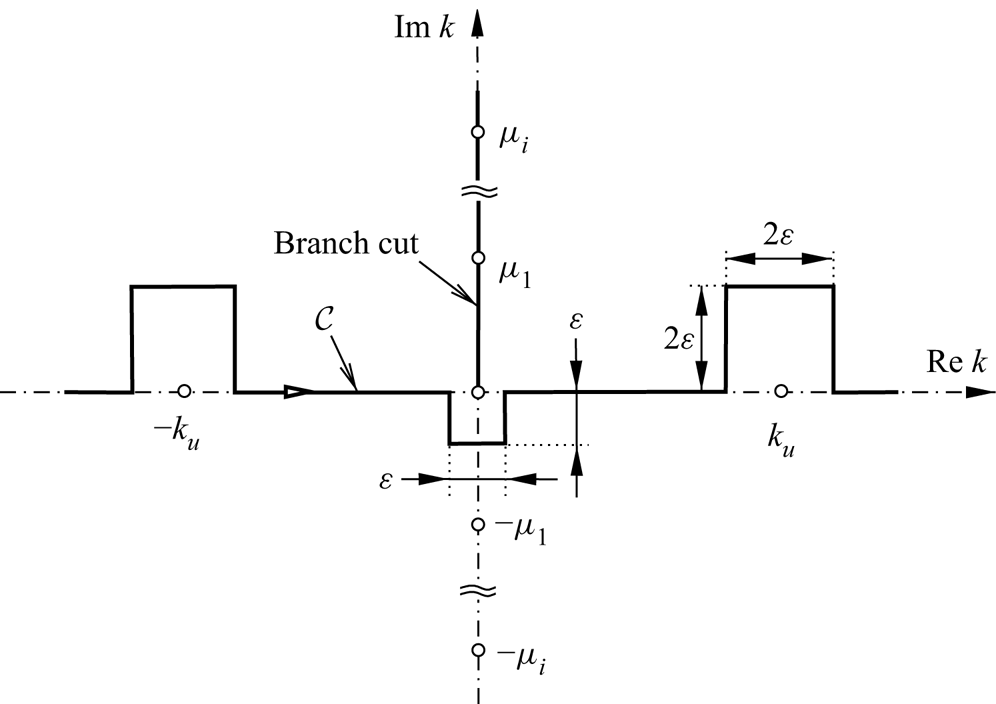
Figure 5. Sketch of  $k$-plane: double-symmetric singular points (circles), actual path $\mathcal {C}$ and direction of integration.
Finally,  $\bar {H}/\bar {\varLambda }$ for ${\bar {X}\leq ~0}$ follows from (3.14c) and directly from (3.24) in a convenient manner. This approach allows us to check the accuracy of the full integration according to (3.23). It is definitely preferred for resolving most accurately the novel discrete undamped capillary Rayleigh modes, forming a wave crest upstream of the edge. These are revealed, as arising from the real poles, with wavenumbers ${k=k_u}$, found to strictly increase as $T$ decreases. Here we point to the classical dispersion relation of small-amplitude capillary waves in a finite-depth layer of uniform parallel flow with uniform speed scaled to unity over a flat bed (see Drazin & Reid Reference Drazin and Reid2004, p. 30 and Vanden-Broeck Reference Vanden-Broeck2010, § 2.4.2 therein). We can infer it directly from that of symmetric Squire modes (Squire Reference Squire1953) as discussed in Appendix B, note that $k/2$ therein is replaced by $k$ here. Such stationary modes then exist for the two wavenumbers ${k=\pm k_u}$ satisfying ${1=T k_u\tanh {k_u}}$. In the current setting we extract from (3.24) the neutral amplitude normalised with $\bar {\varLambda }$,
 \begin{equation} \bar{a}_u:=~2\mathrm{\Gamma}\left({\tfrac{2}{3}}\right){\textrm{Res}}_{k=k_u}[\mathcal{V}(k,h_0)]/ \left(u_0^{+} k_u^{5/3}\right). \end{equation}
A linchpin of the analysis in supplement B is the asymptotic representation of  $k_u$ and ${\textrm {Res}}_{k=k_u}(\mathcal {V})$ as $k_u$ vanishes and $\bar {a}_u$ diverges for ${T\to 1-}$ (§ B.1) as well as the qualitatively reciprocal behaviour for ${T {\rightarrow 0}}$ (§ B.2). In combination with (2.8) (for ${x_v=-1}$), this boils down to the following, numerically valuable, finite limits obtained with high accuracy:
 \begin{gather} k_u/\sqrt{\smash[b]{1-T}}\simeq 1.8046,\quad \bar{a}_u(1-T)^{7/3}\simeq~0.2805 \quad (T\to 1-), \end{gather}
 \begin{gather}k_u T\simeq~1.1596,\quad \bar{a}_u k_u^{2/3}\exp(k_u h_0)\simeq~6.0422 \quad (T{\rightarrow 0}). \end{gather}
 To compute (3.23) (for  ${y=h_0}$), we restrict the numerical integration to the interval ${|\mbox{Re}\,k|\leq ~20}$, which in view of the exponential large- $k$ tails of $\mathcal {V}$ (§ B.2) gives satisfactorily accurate results. Specifically, we find that ${\mathcal{V}(k,h_0)=O(\exp [-|k| h_0]/k)}$. The evaluation of the integrand employs a cubic-spline interpolation of the solution $\mathcal {V}$ of the Rayleigh problem (3.22) for discrete values of $k$. We advantageously mitigated the singularity at ${k=0}$, circumvented at a small distance (see figure 5), by splitting off the first two terms in the small- $k$ expansion of $\mathcal {V}(k,h_0)$ (§ B.1) and finally adding their inverse Fourier transform, which results in the reciprocal large- $\bar {X}$ representation of $\bar {V}$ and $\bar {H}$ via (3.23). We skip the details of this alternative derivation of (3.15) in its more complete form, supplemented with (3.16), also yielding the corresponding asymptote of $\bar {H}$ by integration. To evaluate (3.24) (for ${y=h_0}$) and discrete $\bar {X}$-values, the poles of $\mathcal {V}$ are detected as the roots ${k=k_p}$, say, of $\mathcal {V}^{-1}(k,y)$. Since ${\mathcal{V}\sim {\textrm {Res}}_{k=k_p}(\mathcal{V})/(k-k_p)}$ as ${k\to k_p}$, the according residuals (given by a homogeneous solution to (3.22), see above) are computed as ${1/[ {\partial }_k \mathcal{V}^{-1}(k_p,y)]}$ ( ${y=h_0}$). For ${i>7}$ and $\bar {X}$ lying not too close to zero, the values of the exponentials in (3.24) have already fallen below the round-off error; a few more modes calculated using the asymptotic behaviour of the residuals (§ B.3) were, however, added.
The plots in figures 6 and 7 are also constructed by cubic-spline interpolation of the pointwise data sets. Figure 7(a) displays the results obtained by summation of residuals. As one expects, these are slightly more accurate for very negative values of  $\bar {X}$ and for small values of $T$ than those found by the direct evaluation of (3.23). The contributions of the residua of imaginary poles in (3.24) become only marked when $\bar {H}$ starts to set off from its oscillating behaviour further upstream. Figure 7(b) indicates that excellent agreement with the asymptotes found analytically can be achieved. It is seen that $\bar {H}$ undergoes a trough immediately downstream of the edge before it recovers to rapidly assume the algebraic far-downstream growth governed by (3.15), (3.16) (see also § B.1). The second result in (3.26b) corroborates the extremely rapid upstream decay of the Rayleigh modes found numerically as ${T {\rightarrow 0}}$. Even the maximum value of $k_u$ shown lies on the part of $\mathcal {C}$ considered for the numerical integration, but the suppression of exponentially growing terms in the calculation of $\mathcal {V}$ and the residuals becomes a numerically delicate task when $|k|$ becomes sufficiently large. In the long-wave limit ${k_u {\rightarrow 0}}$ as ${T\to 1-}$, $\bar {\varPsi }$ diverges both immediately upstream of the trailing edge, as $\bar {a}_u$ grows like $k_u^{-14/3}$, and for constant but sufficiently large positive values of $\bar {X}$. Also these findings compare favourably with the curves in figure 7. The intriguing further implications of the long-wave limit are addressed in § 5.


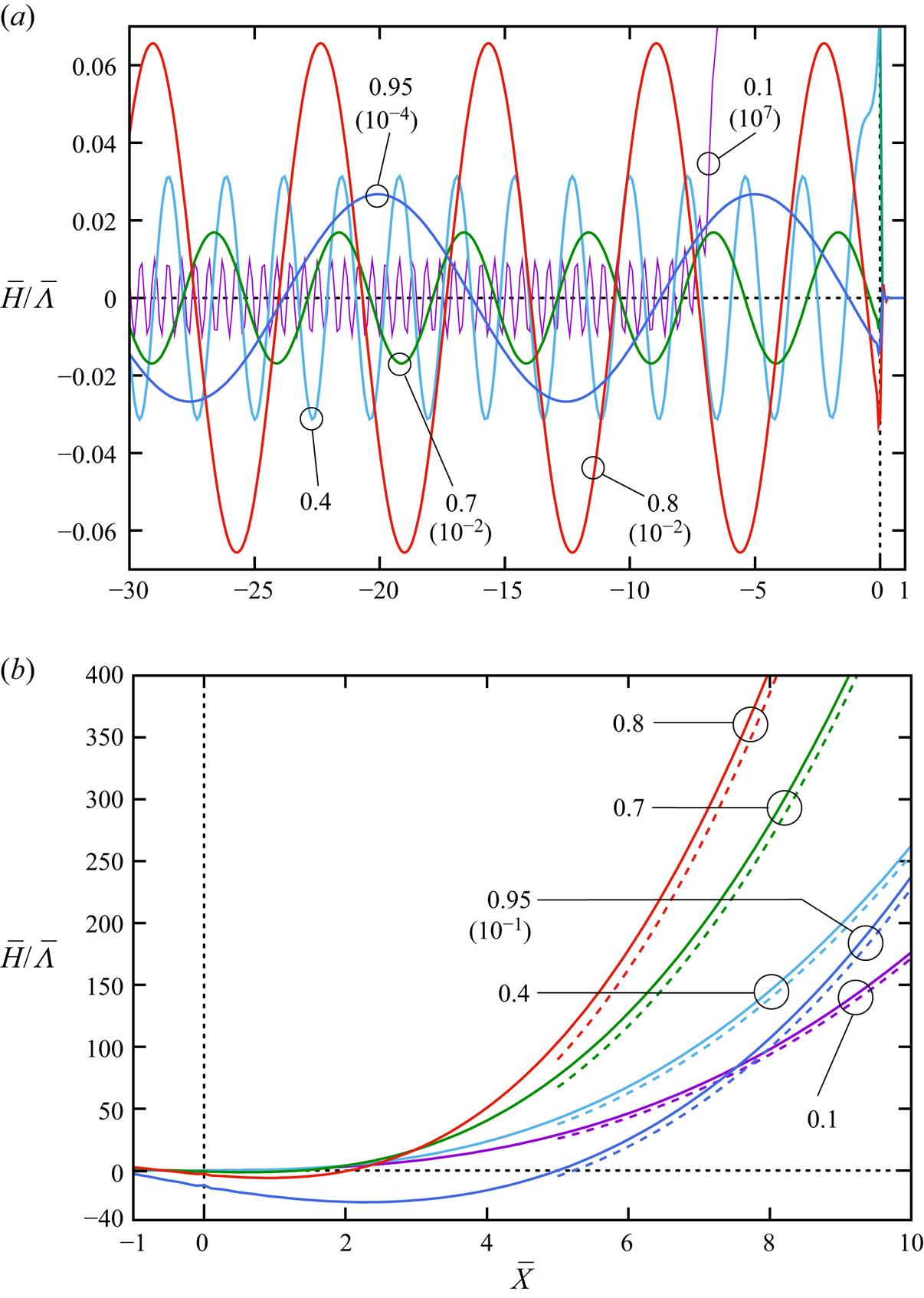
Figure 7. Plots of  $\bar {H}$ vs $\bar {X}$ and $T$ (a) upstream, (b) downstream of trailing edge: labels indicate $T$-values; multiples ${\neq ~1}$ of $\bar {H}$ (in parentheses) shown for enhanced visibility; plot resolution of strongly augmented oscillations for ${T=0.1}$ discerned in (a); two-terms downstream asymptotes (dashed) from (3.15) with (3.16).
We complete the numerical analysis by pointing to the promising agreement between the computed wavelengths  ${\lambda _u:=~2{\rm \pi} /k_u}$ and oscillation amplitudes, see figure 7(a), and those found from the leading-order asymptotes
 \begin{equation} \bar{H}/\bar{\varLambda}\sim{-}(\bar{a}_u/u_0^{+})\cos(k_u\bar{X}-{\rm \pi}/3)\quad (\bar{X}\ll{-}1), \end{equation}
following from (3.24) and (3.14c). For  ${T=0.95}$, (3.26a) predicts ${\lambda _u\simeq ~15.570}$ and ${\bar {a}_u\simeq ~339.741}$; for ${T=0.8}$, (3.26a) still predicts the reasonably good approximation ${\lambda _u\simeq ~7.785}$. For ${T=0.1}$, (3.26b) gives ${k_u\simeq ~11.5960}$ or ${\lambda _u\simeq ~0.5418}$ and $\bar {a}_u/u_0^{+}\simeq ~9.655\times 10^{-10}$ (cf. § B.2), whereas ${k_u\simeq ~11.5570}$ or a slightly larger wavelength ${\lambda _u\simeq ~0.5437}$ is extracted from the numerical data. The details of this case displayed in figure 8 give evidence of the capability of our numerical method to resolve even the rapid oscillations of exponentially small amplitude for small $T$-values with surprisingly high accuracy. In figure 8(b) the difference between the asymptotically and numerically found wavenumbers explains a rather small cumulative phase shift of about $0.3895$ between the curve found numerically and its harmonic approximation provided by (3.27).
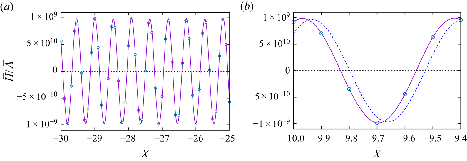
Figure 8. Plots of  $\bar {H}$ vs $\bar {X}$ for ${T=0.1}$ far upstream over (a) several wavelengths, (b) approximately a single wavelength: data points (circles) interpolated by cubic splines (solid) vs harmonic asymptote (dashed) in (b).
3.3.3. Why capillary undulations exist only upstream of the trailing edge
In fact, the decision whether the oscillatory capillary modes occur either up- or downstream of the trailing edge, which depends on whether the real poles are within the lower or upper part of the  $k$-plane divided by $\mathcal {C}$, cannot be left to the present steady-flow analysis. In both cases, these small-scale Rayleigh waves are also manifest above the MD of the interactive flow, modulating their amplitude over the interactive streamwise length scale. We now return to a convincing (although not rigorous) argument restricting their presence to upstream of the edge, as already anticipated in figure 1.
As inferred from the long-wave limit of (3.14a), the Rayleigh-type perturbation of the streamfunction  $(\epsilon ^{2/3})$ in (3.10) morphs into the pressure-free one ${\epsilon ^{2/3}\bar {\varPsi }_{y}(\bar {X},0)\varPsi _0'(Z)}$ in the LD. It exhibits a rapid (harmonic) streamwise variation, either far up- or far downstream. Inspection of (2.3a) shows that typically a further VSL or SL (figure 3b) where ${Z=O(\epsilon ^{1/21})}$ is required on account of the no-slip BC. For very negative values of $\bar {X}$, this shear layer is of the type provoked by the rapid small-scale disturbances considered in Reference Scheichl, Bowles and PasiasSBP18. For ${\bar {X}\ll \epsilon ^{1/7}}$ ( ${X\ll 1}$), it becomes absorbed into the HRW, there serving as the viscous correction of the LD; for larger values of $\bar {X}$, an additional perturbation in the expansion of ${-\epsilon ^{2/3}\bar {\varPsi }_{y}(\bar {X},0){U_{s}}(X)}$ of $h_-$ serves to satisfy the free-slip condition ${\psi _{zz}\sim 0}$ on ${z=0}$ to which (2.3e) reduces; see (2.15).
These observations allow for the existence of the undular modes up- or downstream of the edge, i.e. without preferring one of these alternatives. That is, a steady-flow analysis cannot rule out one of these two possibilities. We therefore justify our choice by making a recourse to the detection of capillary modes exclusively upstream of a wall-mounted obstacle, serving as a compact forcing, by Bowles & Smith (Reference Bowles and Smith1992) and Rayleigh's celebrated radiation principle, which exploits the anomalous dispersion relation for small-amplitude capillarity waves. Acknowledging their essentially inviscid nature in both situations (despite their amplitude of  $O(\epsilon ^{2/3})$ here), we consider this analogy as reasonable.
As a serious objection, however, we have to admit that this principle applies strictly only to a uniform (potential) background flow, where it was adopted by Cumberbatch & Norbury (Reference Cumberbatch and Norbury1979). The last authors also point to the rigorous justification of the above observation by solving the signalling problem, following DePrima & Wu (Reference DePrima and Wu1957). When applied to the current situation (in a separate study), this demands the solution of the unsteady extension of (3.14a) subject to an artificial, spontaneous introduction of the trailing edge in the unperturbed flow described by  $\psi _0$. That is, one expects a pertinent neutral mode for zero frequency in the long-time response in the spectrum, to occur upstream rather than downstream of the edge. An easier modification of this ideal, rigorous approach is the introduction of artificial viscosity and tracing that particular wavenumber in the $k$-plane when the then complex frequency tends to zero (cf. Huerre & Monkewitz (Reference Huerre and Monkewitz1990), § 3.4 therein). This plausibility argument serves to single out the mode upstream as the physically meaningful alternative.
3.3.4. Diffusive overlayer
Expansion (3.10) accounts for the second dynamic BC (2.3e), requiring vanishing shear stress on the top free surface, up to  $O(\epsilon ^{3/7})$, i.e. as long as (2.3e) reduces to ${\psi _{yy}\sim 0}$ on ${y=h_+}$. Moreover, it was indicated in Reference Scheichl, Bowles and PasiasSBP18 how (2.3e) alters the highest-order contribution of $O(\epsilon ^{4/7})$ to the inviscid flow described by (2.11) in a thin layer adjacent to the upper free streamline accounting for viscous diffusion of weak perturbations around the base flow. From inspection of (2.3a), it penetrates to values of ${h_+ -y}$ measured by the square root of its horizontal extent and thus of $O(\epsilon ^{3/7})$. Since the flow therein itself becomes inviscid over the shortened Rayleigh scale, a further diffusion layer of reduced vertical depth arises where $\bar {X}$ and ${\xi :=(y-h_+)/\epsilon ^{1/2}}$ are of $O(1)$ and (2.3e) is formally retained in full. A comprehensive completion of the present self-consistent theory requires a brief examination of this overlayer meeting (2.3e); see supplement C.
3.3.5. Inner Rayleigh stage: lower deck
Following the outline (b) in the preliminaries, see § 3.3.1, the inner square region regularises  $P$ by taking into account the transverse variation of $p$, which becomes of $O(\epsilon ^{6/7})$ according to (3.19a,b) and (3.18a,b) with (3.7). Then (3.10), (3.11) yield the relevant expansion
 \begin{equation} [\psi,p-p_-]\sim\epsilon^{4/7}[(M^{2}/\lambda)^{1/7}\varPsi_0(Y),0]+\epsilon^{6/7}[\hat{\varPsi},\hat{P}](\hat{X},Y)+ O(\epsilon^{20/21}), \end{equation}
where we advantageously revert to the inverse Prandtl transposition in (2.13a–c). Again, the quantities  $\hat {\varPsi }$, $\hat {P}$ describe a linearised Euler flow, now with $\varPsi _0$ providing the base profile. Therefore, ${\hat {V}(\hat {X},Y):= -\hat {\varPsi }_{\bar {X}}}$ satisfies a Rayleigh problem of the type (3.22) except for (3.14c), (3.14d) being replaced by the required decay for large values of ${R:= r/(m\,\epsilon ^{2/7})=(\hat {X}^{2}+Y^{2})^{1/2}}$, where the displacement of the HRW controls $\hat {V}$ by virtue of a $R^{-1/3}$-variation matching (3.19a,b). Since the absence of a free surface at play renders the Rayleigh operator here self-adjoint, all poles lie on the imaginary axis of the corresponding wavenumber plane, which suppresses oscillations of wavenumbers much smaller than those detected in § 3.3.2. Moreover, following the analysis leading to (3.19a,b) recovers the far-field singularity also for ${R {\rightarrow 0}}$.
This shows that the inner RS is unable to fulfil its original task of regularising the pressure provoked by the HRW in the outer RS across the LD, and the associated Rayleigh problem does not therefore merit a more detailed analysis as it proves physically insignificant.
Since the scaled slip  $\bar {\varPsi }_{y}(\bar {X},0)$ exerted by the outer RS becomes of $O(\bar {X}^{1/3})$ as ${\bar {X} {\rightarrow 0}-}$, the vertical extent of the associated SL introduced in § 3.3.3 shrinks typically to ${Y=O(\epsilon ^{1/21}\bar {X}^{1/3})}$. It is continued as a sublayer covering the inner region where ${Y=O(\epsilon ^{1/7})}$ (figure 3c). There the driving slip is replaced by $\hat {\varPsi }_{Y}(\hat {X},0)$, which again attains an $\hat {X}^{1/3}$-behaviour as ${\hat {X}^{1/3} {\rightarrow 0}-}$. We are therefore driven to consider a collapse of the inner RS, the SL and the HRW into a single region (figure 3d), addressed next.
4. Full Navier–Stokes and Stokes regions
As the conditions (2.14h) take into account the detachment of the lowermost streamline but not the edge as a geometric restriction or even its micro-geometry on the length scales considered so far, the prior analysis does not determine whether detachment occurs actually at the edge or further upstream. Therefore, this question is taken up first through an examination of even smaller scales, governing first a full NS regime. This ensues from a breakdown of (3.28) initiated by the unresolved singularity of  $\hat {P}$, just discussed, and the associated unbounded growth of the vertical flow component, $-\hat {\varPsi }_{\hat {X}}$. The associated growth of $v$ evaluated in the HRW shows the emergence of the NS region. We will see that it in turn contains at least one Stokes region around detachment so that the flow can accommodate the wetting properties controlling the emerging meniscus and defined by the thermodynamic three-phase equilibrium holding in the detachment point.
4.1. Leading-order problem in an upper half-plane
The slender-flow approximation underlying (3.1a,b) ceases to be valid where both  $u$ and $v$ become of $O(\epsilon ^{1/2})$ as ${(\bar {x},\bar {y}):=(x/\epsilon ^{3/2},y/\epsilon ^{1/2})}$ and, see (3.18a,b), ${\bar {r}:= r/\epsilon ^{1/2}=(\bar {x}^{2}+\bar {y}^{2})^{1/2}}$ are of $O(1)$. In this half-plane ${0\leq \vartheta \leq {\rm \pi}}$, we expand
 \begin{equation} \left[\psi/\epsilon,\ (p-p_-{+}gy)/\epsilon,\ h_-{/}\epsilon^{2}\right]\sim \left[\bar{\psi}(\bar{r},\vartheta),\ \bar{p}(\bar{r},\vartheta),\ \bar{h}(\bar{x})\right]+O(\epsilon^{3/2}) \end{equation}
with the sought quantities  $\bar {\psi }$, $\bar {p}$, $\bar {h}$ of $O(1)$ as ${\epsilon {\rightarrow 0}}$. Due to the sufficiently smooth variation of the detached streamline beneath the HRW, this remains slender in the present NS region where
 \begin{equation} \bar{y}\sim\epsilon^{3/2}\bar{h}(\bar{x}) \quad\text{or}\quad \vartheta\sim\epsilon^{3/2}\bar{h}(\bar{x})/\bar{x}. \end{equation}
Consequently,  $\bar {\psi }$, $\bar {p}$ satisfy the full NS equations (2.3a,b) describing a perfectly supercritical flow in the upper half-plane. This is subject to mixed, linear, homogeneous BCs implied by (2.3c–e) and a far-field condition which accounts for the externally imposed shear flow. From the reference capillary number in (2.2b), the reduced velocity scale $\sqrt {\smash [b]{\epsilon }}\,\tilde {U}$ and the relative flatness of the detaching streamline given in (4.2), the currently relevant capillary number ${\epsilon ^{1/2}\,{\textit {Ca}}/\epsilon ^{3/2}=1/\tau }$ of $O(1)$ implies the leading-order balance ${2\epsilon ^{2}\psi _{yx}+p-p_-\sim \tau \varkappa _-}$ retained in (2.3e). However, here the normal-stress jump across the fluid–gas interface evaluated at ${\bar {y}=0}$ determines its small curvature ${\varkappa _-\sim \epsilon \bar {h}''(\bar {x})}$, which then has only a passive, higher-order effect on the flow. Accordingly, the weak vertical displacement of the former provokes the $O(\epsilon ^{3/2})$-correction in (4.1), for ${\bar {x} {\rightarrow \infty }}$ matching the displacement by the HRW provided by the inverse Prandtl shift. The neglected lower-order contributions to (4.1) consist of eigensolutions of the linearised NS operator that exhibit asymptotic growth as ${\bar {r} {\rightarrow \infty }}$ so as to match the $O(\epsilon ^{5/7})$-term in (3.28) and higher-order terms apparent in the expansion of $\hat {\varPsi }$, $\hat {P}$ for ${R {\rightarrow 0}}$.
With  ${\bar {{\rm \Delta} }:=\bar {r}^{-1} {\partial }_{\bar {r}}(\bar {r} {\partial }_{\bar {r}})+\bar {r}^{-2} {\partial }_{\vartheta \vartheta }}$ being the Laplacian, the leading-order NS problem reads as
 \begin{gather} \bar{\psi}_{\vartheta}(\bar{\psi}_{\vartheta}/\bar{r})_{\bar{r}}-\bar{\psi}^{2}_{\bar{r}}- \bar{\psi}_{\bar{r}}\bar{\psi}_{\vartheta\vartheta}/\bar{r} ={-}\bar{r}\bar{p}_{\bar{r}}+\bar{{\rm \Delta}}\bar{\psi}_{\vartheta}, \end{gather}
 \begin{gather}\bar{\psi}_{\bar{r}}\bar{\psi}_{\bar{r}\vartheta}-(\bar{r}\bar{\psi}_{\bar{r}})_{\bar{r}}\bar{\psi}_{\vartheta}/\bar{r} ={-}\bar{p}_{\vartheta}-\bar{r}(\bar{{\rm \Delta}}\bar{\psi})_{\bar{r}}, \end{gather}
supplemented with (2.3c–e) when evaluated for  ${\bar {y}=\vartheta =0}$,
 \begin{gather} \vartheta=0\colon\enspace \bar{\psi}=0,\quad \bar{\psi}_{\vartheta\vartheta}=0,\quad 2(\bar{\psi}_{\vartheta}/\bar{r})_{\bar{r}}+\bar{p}=\tau\bar{h}'', \end{gather}
 \begin{gather}\vartheta={\rm \pi}\colon\enspace \bar{\psi}=\bar{\psi}_{\vartheta}=0. \end{gather}
Matching  $\psi$ and $p$ in the NS and the surrounding inner Rayleigh region, i.e. (4.1) and (3.28), completes the problem (4.3) governing $\bar {\psi }$, $\bar {p}$ and $\bar {h}$. We have for
 \begin{equation} \bar{r}{\rightarrow\infty}\colon\enspace \bar{\psi}\sim(\varLambda_0/2)(\bar{r}\sin{\vartheta})^{2}+o(\bar{r})\quad (\vartheta\gg\bar{r}^{{-}2/3},\enspace {\rm \pi}-\vartheta\gg\bar{r}^{{-}2/3}),\quad \bar{p}{\rightarrow 0}. \end{equation}
The smallness of the remainder term imposed on  $\bar {\psi }$ provides the required second kinematic far-field BC. Since we are dealing with the full NS equations, (4.3) already captures the inner Rayleigh region and its subregions both upstream (SL) and downstream (HRW, ${\bar {y}\sim \bar {r}\vartheta =O(\bar {r}^{1/3})}$ there) of detachment; cf. figure 3(d). That is, (4.3e) already implies that ${(\bar {\psi },\bar {p})=O(\bar {r}^{2/3})}$ and ${\bar {h}=O(\bar {r}^{8/3})}$ at the onset of the HRW. The BCs for ${\vartheta =0}$ in (4.3c) describe zero tangential stress along the detached streamline and the net normal-stress jump across it. Eventually, eliminating $\bar {p}$ from (4.3a,b) yields the vorticity transport equation
 \begin{equation} (\bar{\psi}_{\vartheta}\,{\partial}_{\bar{r}}-\bar{\psi}_{\bar{r}}\,{\partial}_{\vartheta})\bar{{\rm \Delta}}\bar{\psi}=\bar{r}\bar{{\rm \Delta}}^{2}\bar{\psi}, \end{equation}
to be solved subject to the first two BCs in (4.3c) and (4.3d,e). Hence,  $\bar {\psi }$ is solely induced and parametrised by the externally exerted shear rate $\varLambda _0$. We recall that this is determined by the solution of the viscous–inviscid interaction problem on a larger scale and accounts for the upstream momentum flux, gravity and capillarity.
The variation of  $\bar {h}$ with $\bar {r}$ is then found from integrating the capillary normal-stress jump in (4.3c) and, given the identical match of $\bar {h}$ and $H_-$ according to (3.1a,b), two ICs to be imposed as ${\bar {r} {\rightarrow 0}}$. Before tackling their determination, we first identify the flow topology near detachment, solely based on the information extracted from the NS problem posed above in the limit ${\bar {r} {\rightarrow 0}}$. The importance of this insight by far outweighs the perspective of obtaining the full numerical solution. Therefore, we have refrained from tackling this considerable challenge. (The considerations below suggest spectral collocation in the $\vartheta$-direction as the method of choice.)
4.2. Flow close to detachment
As  $\bar {\psi }$ must satisfy four BCs in (4.3c,d), the viscous terms are retained in the limiting forms of (4.3a,b) as ${\bar {r} {\rightarrow 0}}$ and ${\vartheta \in [0,{\rm \pi} ]}$. Requiring strict forward flow in the immediate vicinity of detachment,
 \begin{equation} \bar{\psi}>0\quad (\bar{r}{\rightarrow 0}), \end{equation}
is initially seen as a natural additional constraint. It is supported by the extensive numerical investigation by Kistler & Scriven (Reference Kistler and Scriven1994) of the full NS problem for a flow passing a wedge-shaped lip, see figures 2(b) and 3( f): this predicts an eddy at its underside in some situations associated with rather low to moderate Reynolds numbers but strictly forward flow detaching at its tip in the present high-Reynolds-number limit. The analysis below, however, demonstrates that (4.5) is only met in the least singular situation chosen from the initial alternatives.
4.2.1. The full inertial–viscous limit
The convective–viscous balance in (4.4) is restored in full if  $\bar {\psi }$ varies essentially with $\ln {\bar {r}}$,
 \begin{equation} \bar{\psi}\sim\bar{g}(\vartheta)-\varGamma\ln{\bar{r}}/(2{\rm \pi})\quad (\bar{r}{\rightarrow 0}),\quad \varGamma\bar{g}'''/(2{\rm \pi})-2\bar{g}'\bar{g}''=(4\bar{g}+\bar{g}'')''. \end{equation}
We are thus concerned with a spiralling extension of a special type of a radial Jeffery–Hamel (JH) flow described by  $\bar {g}(\vartheta )$ (see Fraenkel Reference Fraenkel1962), exhibiting the vorticity ${-\bar {{\rm \Delta} }\bar {\psi }=-\bar {g}''/\bar {r}^{2}}$ and an outwards flow speed $\bar {g}'(\vartheta )/\bar {r}$ as collapsing in a line source of strength $\bar {g}'(\vartheta )$, due to a superimposed potential vortex of some strength $\varGamma$. Here the homogeneous BCs ${\bar {g}(0)=\bar {g}''(0)=\bar {g}({\rm \pi} )=\bar {g}'({\rm \pi} )=0}$ originating in (4.3c,d) require ${\varGamma =0}$, and $\bar {g}$ represents an eigensolution of the full NS problem. Nevertheless, the case ${\varGamma \neq ~0}$ and ${\bar {g}''\not \equiv 0}$, apparently unconsidered before now, might be of interest in a different context. We also remark that for an inviscid flow, removing the Stokes operator in (4.6a,b), $\bar {g}(\vartheta )$ varies sinusoidally in general but linearly in the case of a potential flow.
An analytical–numerical study shows that there exist two eigensolutions  $\bar {g}$. Each describes a distinctly different canonical flow topology as both exhibit a dividing streamline ${\bar {g}=0}$ for ${\vartheta =\vartheta _0\simeq ~1.12777}$ and, thus, violate the premise (4.5) and point to the existence of a closed reversed-flow eddy. This is located either adjacent to the plate ( ${\bar {g}<0}$ for ${\vartheta _0<\vartheta <{\rm \pi} }$) or fully detached as bounded by the free streamline ( ${\bar {g}<0}$ for ${0<\vartheta <\vartheta _0}$); see figure 9(a). In the first case, the flow undergoes pre-separation to reattach in the origin ${\bar {r}=0}$; in the second, the free streamline attaches rather than detaches there from the plate. These flow pictures are the immediate consequence of including azimuthal higher-order corrections to the purely radial JH flow and extending the streamline pattern over the full NS scales; see figure 9(b). However, our scrutiny of the related literature does not inform about what, at first sight, is a rather pathological situation. In particular, the conception of a detached eddy with a stagnation point forming at the free and material streamline, to which the fluid particles stay attached, raises serious concerns.

We therefore rule out the JH solution as the local limit of the full NS solution. Notwithstanding its apparent shortcoming, however, we refer the interested reader to the higher-order corrections and some of the further impact of this limit in supplement D. These findings are not required for the core arguments at present but are potentially of interest for pursuing the study of this flow structure in a related context.
4.2.2. An extended Stokes limit as the alternative
Discarding the possibility of a full inner NS problem, (4.6a,b), leaves us with the degenerate situation of the dominant Stokes balances
 \begin{equation} 0\sim\bar{{\rm \Delta}}^{2}\bar{\psi},\quad \bar{p}_{\bar{r}}\sim\bar{{\rm \Delta}}\bar{\psi}_{\vartheta}/\bar{r},\quad \bar{p}_{\vartheta}\sim{-}\bar{r}(\bar{{\rm \Delta}}\bar{\psi})_{\bar{r}} \end{equation}
and  ${\bar {\psi } {\rightarrow 0}}$ as the origin ${\bar {r}=0}$ is approached along any path from within the flow. We then expand $\bar {\psi }$ into the eigensolutions $\bar {\psi }_i$ of the biharmonic operator in (4.7a,b) when supplemented with the homogeneous BCs in (4.3c,d) found by separation in the polar variables, following Moffatt (Reference Moffatt1964) and the references therein. However, here the subordinate convective terms in (4.4) control their admissibility and, thus, the form of the dominant eigensolution. This straightforward but long-winded selection process is detailed in supplement E. As the most significant result, it predicts regular behaviours for ${\bar {r} {\rightarrow 0}}$ towards a separating flow ( ${\bar {\psi }_{\bar {y}\bar {y}}=0}$),
 \begin{gather} \bar{\psi}\sim{-}4a_5\bar{y}^{3}+o(\bar{r}^{3}),\quad \bar{p}-\bar{p}_0\sim{-}24a_5\bar{x}+o(\bar{r})\quad (a_5<0,\ \bar{r}{\rightarrow 0}), \end{gather}
 \begin{gather}\bar{h}\sim\bar{h}(0)+\bar{h}'(0)\bar{x}+\bar{p}_0\bar{x}^{2}/(2\tau)-4 a_5\bar{x}^{3}/\tau+o(\bar{x}^{3})\quad (\bar{x}{\rightarrow 0}+). \end{gather}
The constant  $a_5$ and the offset pressure $\bar {p}_0$ are part of the solution to the full NS problem, in turn, forced by the value of $\varLambda _0$. Let us first indicate how to fix the unknown coefficients $\bar {h}(0)$ and $\bar {h}'(0)$, governing the local elevation of the just detached streamline, and complete our analysis at this stage, i.e. without taking into consideration any smaller length scale.
As an obvious geometrical requirement,  ${\bar {h}(0)=0}$ then. In full agreement with the current status of the theory, the position of flow detachment not only defines the origin ${x=y=0}$ but an arbitrary point of the upper side of the plate rather than necessarily coinciding with the trailing edge, as a genuine geometrical constraint. Detachment further upstream then requires the actual static wetting or contact angle, observed in the NS region, as an input quantity being so close to ${\rm \pi}$ that it is approximated by ${{\rm \pi} -\epsilon ^{3/2}\bar {h}'(0)}$. This determines a positive value of $\bar {h}'(0)$. However, and as an immediate consequence of the slenderness of the lower free streamline, this thereby resulting distinguished limit refers to the quite exceptional break-away of an almost perfectly hydrophobic liquid. Additionally, such a scenario demands for the geometrical constraint ${\bar {h}>0}$ for ${\bar {x}>0}$, which admittedly cannot be guaranteed as long as the numerical solution of the above NS problem is not available. It is also not likely to occur in reality, where unavoidable (though here neglected) surface imperfections already affect the flow described on the vertical NS scale. It is a natural step, therefore, to identify the location of flow detachment indeed at the trailing edge. However, then $\bar {h}'(0)$ remains undetermined as long as its microscopic shape remains unresolved.
The outcome of these considerations is threefold. Firstly, we expect both  $\bar {h}(0)$ and $\bar {h}'(0)$ to be fixed by conditions of matching the full NS and a Stokes flow in a hidden region of an extent much smaller than that of the encompassing NS region. Secondly, as we raised in the introduction to § 4, the description of that creeping flow must take into account the meniscus formed by the actual slope of the free streamline at its detachment point of three-phase contact as a hitherto unconsidered physical input. And thirdly, that a new length scale must resolve the microscopic contour of the plate with sufficient accuracy.
4.3. Distinguished Stokes limits and wetting properties
Although possibly not satisfied in a particular realisation of the flow, let us treat the surface of the plate as locally chemically heterogeneous and ignore distributed roughness on all scales for the sake of clarity. Then the so-called quasi-static apparent contact angle,  $\beta$, is observed between the wetted plate and the tangent to the free streamline at its point of detachment and formation, where three phases (locally) at rest meet under the Young–Dupré equilibrium: for its precise conceptual foundation, we refer to Teletzke, Davies & Scriven (Reference Teletzke, Davies and Scriven1988), Kistler & Scriven (Reference Kistler and Scriven1994), Whyman, Bormashenko & Stein (Reference Whyman, Bormashenko and Stein2008) and Bonn et al. (Reference Bonn, Eggers, Indekeu, Meunier and Rolley2009). Since this macroscopic contact angle summarises all related submicroscopic phenomena (see Kistler & Scriven (Reference Kistler and Scriven1994), and references therein) and shall apply even to the smallest scales identified in the flow, we have consistently used the notion ‘microscopic’ in the context of the resolved geometry of the trailing edge.
4.3.1. Nested Stokes problems
To progress further, we introduce the new length scale  ${\ell \ll \epsilon ^{1/2}}$, non-dimensional with the nominal film thickness $\tilde {H}$. In the new flow region, ${[\hat {x},\hat {y}]:=[x/(\epsilon \ell ),y/\ell ]}$ and ${\hat {r}:= r/\ell =(\hat {x}^{2}+\hat {y}^{2})^{1/2}}$, see (3.18a,b), are of $O(1)$ as ${\ell {\rightarrow 0}}$. Hence, supplementing (4.1) with (4.8), the associated increase of ${\bar {p}-\bar {p}_0}$ and (4.8b) suggests the two-parameter expansion
 \begin{equation} \left[\frac{\psi}{\ell^{3}\,\epsilon^{{-}1/2}}, \frac{p-p_-{+}gy-\epsilon\bar{p}_0}{\ell\,\epsilon^{1/2}},\frac{h_-}{\ell}\right]\sim \left[\hat{\psi}(\hat{x},\hat{y}),\hat{p}(\hat{x},\hat{y}),\hat{h}_0(\hat{x})+\frac{\ell}{\epsilon^{1/2}}\hat{h}_1(\hat{x})\right]. \end{equation}
The  $O(1)$-quantities $\hat {\psi }$, $\hat {p}$, $\hat {h}_0$ and the only first-order correction of interest $\hat {h}_1$ are to be found. The scaled elevation ${\hat {h}(\hat {x}):= h_-/\ell }$ of the detaching streamline remains to be determined by the capillary normal-stress jump in (2.3e). Since ${\hat {p}\sim \epsilon \bar {p}_0+O(\ell \epsilon ^{1/2})}$ and all viscous terms on its left side are found to be of $O(\ell \epsilon ^{1/2})$, that becomes of ${\epsilon \bar {p}_0+O(\ell \epsilon ^{1/2})}$ in the limit (4.9). However,
 \begin{equation} \varkappa_-{\sim}\ell^{{-}1}\hat{h}''/(1+\hat{h}'^{2})^{3/2}, \end{equation}
stating that the capillary number at play,  $\ell ^{2}\epsilon ^{1/2}/\tau$, is small. This is also inferred from reducing ${\textit {Ca}}$ in (2.2b) by the small relative velocity scale $\ell ^{2}/\epsilon ^{1/2}$. In turn, ${\hat {h}''\equiv 0}$, and matching (4.9) and (4.8b) shows that the lower free streamline remains horizontally inclined under an angle no larger than of $O(\epsilon ^{3/2})$. Accordingly,
 \begin{equation} \hat{h}_0=\bar{h}(0)/\varDelta,\quad \hat{h}_1=\bar{h}'(0)\,(\hat{x}-\hat{x}_d)/\varDelta. \end{equation}
Here the parameter  $\varDelta$ measures the strength of the required distinguished limit,
 \begin{equation} \ell=\varDelta\epsilon^{2},\quad 0<\varDelta=O(1), \end{equation}
and  ${(\hat {x},\hat {y})=(\hat {x}_d,\hat {h}_0)}$ denote the position of the actual detachment point, $\mathcal {D}$, taken initially to be known.
Let  $\varSigma$ denote the resolved surface of the plate. Inspection of (2.3) and the behaviour (4.11a,b) confirm that the leading-order quantities $\hat {\psi }$, $\hat {p}$ satisfy
 \begin{equation} \hat{{\rm \Delta}}^{2}\hat{\psi}=0,\quad \hat{p}_{\bar{x}}=\hat{{\rm \Delta}}\hat{\psi}_{\bar{y}},\quad \hat{p}_{\hat{y}}={-}\hat{{\rm \Delta}}\hat{\psi}_{\hat{x}},\quad \hat{{\rm \Delta}}:={\partial}_{\hat{x}\hat{x}}+{\partial}_{\hat{y}\hat{y}}, \end{equation}
subject to mixed boundary conditions in the limit of zero capillary number as
 \begin{gather} \hat{r}{\rightarrow\infty}\colon\enspace \hat{\psi}\sim{-}4a_5\hat{y}^{3}+o(\hat{r}^{5/2}), \end{gather}
 \begin{gather}\text{on}\enspace \varSigma\ (\hat{x}<\hat{x}_d)\colon\enspace \hat{\psi}=\hat{\psi}_{\hat{y}}=0, \end{gather}
 \begin{gather}\hat{y}=\hat{h}_0\enspace (\hat{x}\geq\hat{x}_d)\colon\enspace \hat{\psi}=\hat{\psi}_{\hat{y}\hat{y}}=0. \end{gather}
Once  $\hat {\psi }$ is found, one can calculate $\hat {p}$ by integration, giving ${\hat {p}\sim -24 a_5\hat {x}+O(1)}$. This matches identically the small- $\bar {r}$ form of $p$ in (4.8a) as the remainder term negotiates a constant of integration found from the $O(\epsilon ^{3/2})$-contribution to (4.1). In accordance with the above results and likewise, the neglected remainder term in (4.13b) expresses the second necessary far-field condition and the absence of an eigensolution of the NS problem of $O(\epsilon ^{3/4})$ that would enter the right-hand side of (4.1). This seems to be a natural choice, as (3.28) would require it to die out for large values of $\hat {r}$. Rather, (4.13d) enforces an $O(1)$-correction $a_5\hat {g}(\vartheta )$, say, in the large- $\hat {r}$ form of $\hat {\psi }$. The function $\hat {g}$ is then governed by
 \begin{align} (4\hat{g}+\hat{g}'')''=0,\quad \hat{g}(0)={-}4a_5\hat{h}_0^{3},\quad \hat{g}''(0)={-}24a_5\hat{h}_0,\quad \hat{g}({\rm \pi})=\hat{g}'({\rm \pi})=0; \end{align}
cf. (4.6a,b). Eventually,
 \begin{align} \frac{\hat{\psi}}{a_5}\sim{-}4\hat{y}^{3}\cdots+\hat{g}(\vartheta)+o(1),\quad \hat{g}={-}6\hat{h}_0(\sin{\vartheta})^{2}-4\hat{h}_0^{3}\left[1+\frac{\sin(2\vartheta)}{2{\rm \pi}}-\frac{\vartheta}{\rm \pi}\right], \end{align}
where the dots indicate potential eigensolutions of  $o(\hat {r}^{2})$. The behaviours in (4.15a,b) provide the match of (4.9) with (4.1) supplemented with an $O(\epsilon ^{9/2})$-contribution, hence, also excited by the displacement (4.2) of the interface. While that of $O(\epsilon ^{3/2})$ is controlled by the linearisation of $\bar {\psi }$ as ${\bar {y} {\rightarrow 0}}$, this is due to the corresponding third-order terms. As these dominate as ${\bar {r} {\rightarrow 0}}$ where ${\bar {\psi }\sim 4 a_5\bar {y}^{3}}$, evaluating $\hat {g}$ for ${\vartheta {\rightarrow 0}}$ describes the feedback of the displacement on the flow near detachment.
We note that the weak curvature of the detaching streamline is determined by the higher-order approximation of (2.3e), following from (4.10) as
 \begin{equation} \tau\hat{h}''\sim\epsilon\ell\bar{p}_0+2\epsilon^{1/2}\ell^{2}\hat{\psi}_{\hat{x}\hat{y}}\quad (\hat{y}=\hat{h}_0). \end{equation}
 The case of a perfectly flat surface associated with  ${\hat {h}_0\equiv 0}$ and the trivial solution ${\hat {\psi }=-4 a_5\hat {y}^{3}}$ of (4.13) recovers the dominant Stokes limit of the full NS solution for ${\bar {r} {\rightarrow 0}}$ and the aforementioned pathological case of fully hydrophobic dewetting with both $x_d$ and $\ell$ then remaining unspecified. This situation is therefore ruled out, and we are indeed left with flow detachment in a vicinity of the originally sharp plate edge covered by the Stokes region, where the microscopic resolution of the edge dictates the definition of $\ell$. We henceforth refer to the sketch of the flow around the resolved edge in figure 10, detailing figures 2(b) and 3( f) on the new scale for various values of $\beta$ (cf. Duez et al. Reference Duez, Ybert, Clanet and Bocquet2010). As previously discussed, the edge is, without substantial loss of generality, assumed to be given by a smoothed but at first ideal wedge of cut-back angle $\alpha$ and with an apex lying at the coordinate origin. Then the curvature radius typical of the rounded nose conveniently defines $\ell$; the degenerate situation of a wedge still found sharp when viewed on the scale $\epsilon ^{2}$ is assumed in the limit ${\varDelta {\rightarrow 0}}$. The case of specific relevance ${\alpha =0}$ can be interpreted as a plate-type thin tip formed by a semi-circle and of local thickness $2\ell$ (figure 10b). Although the film generated by Duez et al. (Reference Duez, Ybert, Clanet and Bocquet2010) is much thinner and thus the scales different, we find the comparison of their experimental with our theoretical prediction noteworthy (figure 10c).
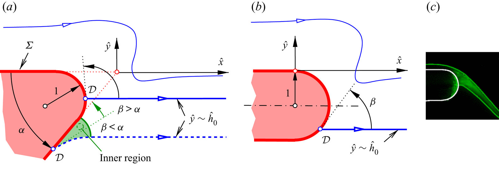
Figure 10. Stokes flow around resolved smoothed trailing edge: (a) wedge-type ( ${\alpha >0}$), inner region emerging for ${\beta <\alpha }$ (green); (b) plate-type and semi-circular ( ${\alpha =0}$), no inner region; (c) cut of liquid interfaces in experiment, described in and reprinted with permission from Duez et al. (Reference Duez, Ybert, Clanet and Bocquet2010) (© the American Physical Society).
Assuming  ${\varDelta =1}$ in (4.12a,b) and ${\tilde {H}=1\ \text {mm}}$ (table 1 in Appendix A) typically gives a quite small physical scale ${\ell \tilde{H}\simeq 0.01 - 0.04\ \mathrm {\mu }\text {m}}$. However, it is large enough to consider the asymptotic theory applicable to curvature radii achieved in manufacturing practice.
Completing our flow model at this stage is indeed possible for a non-degenerate, smoothed wedge tip and a sufficiently large apparent wetting angle  $\beta$ as the wedge geometry imposes a closure condition on (4.13). This fixes the location of $\mathcal {D}$
 \begin{equation} \text{on}\ \varSigma\colon\ \text{d}\hat{y}/\text{d}\hat{x}\sim\tan{\beta}+o(\epsilon^{3/2}). \end{equation}
This describes the general, non-degenerate case where  $\bar {h}(0)$ is found in virtue of (4.11a,b). Evidently, then also ${\hat {h}'(0)=0}$ as the linear follow-up problem to (4.13) governing disturbances of $O(\ell /\epsilon ^{1/2})$ in (4.9) has the zero solution. Higher-order perturbations, already affected by the curvature of the detached streamline, control the (physically insignificant) remainder term in (4.17). Proceeding in this manner determines successively the two ICs that each term arising in the expansion of $h_-$ in (4.1) has to meet as ${\bar {r} {\rightarrow 0}}$. This consideration confirms self-consistency of the proposed theoretical framework. As a crucial result, the flow wets the underside of the wedge as $\hat {h}_0$ represents a (strictly) monotonic function of $\beta$, which decreases from $0$ as $\beta$ decreases from ${\rm \pi}$. This justifies our reference to the teapot effect. The pathological limit ${\beta \to {\rm \pi}-}$ or ${(\hat {x}_d,\hat {h}_0)\to (0,0)}$, however, leads to a non-trivial value of $\hat {h}'(0)$. Here we only note that the above analysis by inspection gives ${\ell =O(\epsilon )}$ in the degenerate case ${\bar {h}(0)=0}$, ${\bar {h}'(0)>0}$. On the other extreme, $\mathcal {D}$ has reached the point on the nose where its curvature vanishes once $\beta$ has become as small as $\alpha$. All together, we arrive at the geometrical constraint
 \begin{equation} {\rm \pi}-\epsilon^{3/2}\bar{h}'(0)\geq\beta\geq\alpha. \end{equation}
The variation of  $\hat {h}_0$ with $\beta$ is more and more squeezed towards the edge as this gets sharpened. Finally, $\mathcal {D}$ is seen as pinned to the edge as (4.18) is interpreted as the well-known Gibbs inequality; see Oliver, Huh & Mason (Reference Oliver, Huh and Mason1977), Dyson (Reference Dyson1988) and Kistler & Scriven (Reference Kistler and Scriven1994). In accordance with the last authors, we find that the distance of $\mathcal {D}$ from the apex decreases with both increasing values of $\beta$ and the Reynolds number.
The formidable task of solving the Stokes problem (4.13), parametrised by  $\alpha$ and $\beta$, has not yet been accomplished. Most importantly, in the situation sketched in figure 10(b), mastering this challenge will establish a comprehensive flow description in the entire range ${{\rm \pi} >\beta >0}$ of physical significance. If, however, ${\beta \geq \alpha }$, determining the actual position of $\mathcal {D}$ requires the introduction of a further, inner Stokes region, as indicated in figure 10(a). Contrasting with its counterpart (4.13), there the governing problem is of a non-degenerate free-surface type, thus controlled by a capillary number of $O(1)$, to accommodate to the necessary local bending of the detaching streamline. We expect $\mathcal {D}$ to be found the further away from the apex the smaller is the value of $\beta$, with its position fixed by a constraint arising of the interplay of these nested Stokes regions. This is a topic of our upcoming activities. Adhering to the scalings of the outer region, however, and using (4.10) gives as a first result for the approach to $\mathcal {D}$,
 \begin{equation} \hat{h}'\to\tan(\alpha-\beta),\quad \varkappa_-{\sim}\ell^{{-}1}[\cos(\alpha-\beta)]^{3}\hat{h}''\quad (\hat{x}\to\hat{x}_d). \end{equation}
4.3.2. Static wetting angle
As the final step, we focus on the flow properties in the immediate vicinity of detachment, specified either on conditions (4.18) or (4.19a,b). Here we again follow Moffatt (Reference Moffatt1964) in his analysis of local eigensolutions of (4.13) varying algebraically with distance from a singular point at a rigid wall. These suggest that the streamlines are locally pushed away from the nose. Moffatt (Reference Moffatt1964, § 3.2) also showed that a related class of eigensolutions controls the behaviour of  $\hat {\psi }$ at small distances ${\hat {d}=[(\hat {x}-\hat {x}_d)^{2}+(\hat {y}-\hat {h}_0)^{2}]^{1/2}}$ from the detachment point: using (4.13a,c,d) and reusing the azimuthal angle, ${\vartheta :=\arctan [(\hat {y}-\hat {h}_0)/(\hat {x}-\hat {x}_d)]}$, yields first for (4.18) and ${0\leq \vartheta \leq \beta }$ in the limit
 \begin{align} \hat{d}{\rightarrow 0}\colon\enspace \frac{\hat{\psi}}{\hat{a}\hat{d}^{\,\sigma}}\sim\left\{\begin{array}{@{}ll} \sin(\sigma\vartheta)\sin[(\sigma-2)\beta]-\sin(\sigma\beta)\sin[(\sigma-2)\vartheta]+{\rm c.c.} & (\sigma\neq~2), \\ \sin(2\vartheta)-\vartheta/\beta & (\sigma=2). \end{array}\right. \end{align}
The constant  $\hat {a}$ is determined by the full solution to (4.13), and $\sigma$ appears to be a (complex) eigenvalue related to $\beta$ by
 \begin{equation} (\sigma-1)\sin(2\beta)=\sin[2\beta(\sigma-1)]\enspace (\sigma\neq~2),\quad \tan(2\beta)=2\beta\enspace (\sigma=2). \end{equation}
 Thus, a continuous relationship requires  ${\beta \simeq ~128.727^{\circ }}$ for ${\sigma =2}$. One readily confirms that the eigensolutions considered in § 4.2.2 are recovered in the limit ${\beta \to {\rm \pi}}$. Equation (4.21a,b) is symmetric with respect to ${\mbox{Re}\,\sigma -1}$. However, physically admissible solutions require the flow speed, of $O(\hat {d}^{\,\sigma -1})$, to vanish and the shear and the normal stress (the pressure), both of $O(\hat {d}^{\,\sigma -2})$, on $\varSigma$ being integrable as ${\hat {d} {\rightarrow 0}}$ (and not to compromise the validity of the Young–Dupré equilibrium). According to (4.16), $\hat {h}''$ varies at the same rate. Therefore, only values of $\sigma$ having ${\mbox{Re}\,\sigma >1}$ are permitted, anticipated by the requirement ${\hat {\psi }=0}$ and a finite slope $\hat {h}'$ at detachment in (4.13d) and, thus, the existence of a static contact angle $\beta$. The plot of the real branches of (4.21a,b) in figure 11 illustrates the infinite multiplicity of $\sigma$, not considered by Moffatt (Reference Moffatt1964), the asymptotes ${\beta \to {\rm \pi}/2,\,{\rm \pi} }$ as ${\mbox{Re}\,\sigma {\rightarrow \infty }}$ and the local extrema of $\beta$. There (4.21a,b) is continued to complex values of $\sigma$, via (4.20) associated with Moffatt's (Reference Moffatt1964) prominent and exceptional infinite sequence of eddies. Hence, our flow model does not predict a single eddy as do the calculations by Kistler & Scriven (Reference Kistler and Scriven1994) for moderately large Reynolds numbers. Rather, it predicts this series of eddies if the value of $\beta$ falls below its absolute minimum. Moffatt (Reference Moffatt1964) predicted this well-established threshold as $\simeq 78^{\circ }$; here we recompute it as $\simeq 79.557^{\circ }$ for ${\sigma \simeq ~3.7818}$.
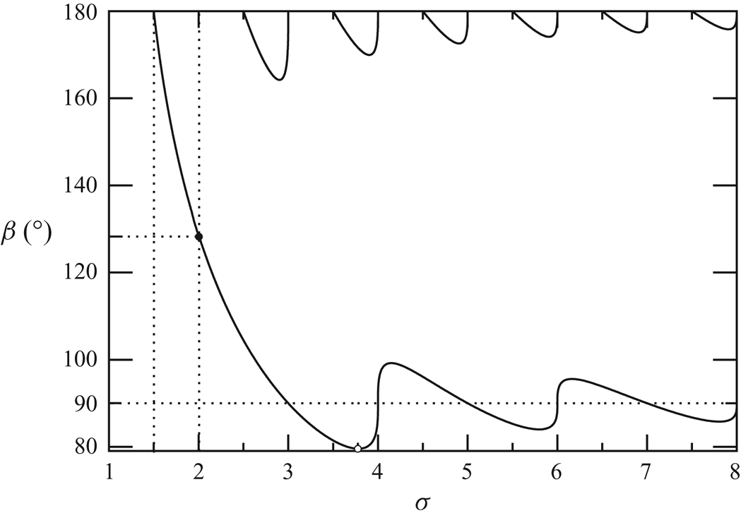
Figure 11. Allowed contact angle  $\beta$ vs real $\sigma$, from (4.21a,b); existent for $\sigma >3/2$, smooth for $\sigma =2$ (full circle) and having a local absolute minimum (empty circle).
A more elaborate discussion of these details and their consequences requires the yet pending full numerical solution of (4.13). Since (4.21a,b) is independent of the choice of the coordinate system used, however, the above results remain valid in the vicinity of the apex  $\mathcal {D}$ of the wedge-shaped inner Stokes region if (4.18) is violated (figure 10b). According to (4.19a,b), $\hat {h}''$ is then again integrable. As a crucial finding, these local properties characterise in general the solution of a Stokes problem governing flow detachment at some finite capillary number.
Moreover, as these results rely solely on the leading-order term of the Stokes expansion, they even hold for a finite-Reynolds-number flow around a resolved top; cf. Silliman & Scriven (Reference Silliman and Scriven1980) and Kistler & Scriven (Reference Kistler and Scriven1994).
5. Conclusions and further perspectives
As an unexpected extension of the interactive flow structure around flow detachment at the free plate edge, we report neutral capillary Rayleigh modes on the upper free surface solely and immediately upstream of the edge. Demonstrating this confidently calls for solving a signalling problem where typically a compact forcing dividing the flow into an upstream and a downstream part. Here this is provided by a delta functional describing the transition of the vertical flow component over the geometric discontinuity formed by the trailing edge but tied in with an additional non-compact excitation by the displacement of the HRW, necessary to provoke the non-trivial Rayleigh state.
The small-scale/small-amplitude ripples differ markedly in their origin from those already predicted by Bowles & Smith (Reference Bowles and Smith1992) upstream of a wall-mounted obstacle over the interactive length scale. Accordingly, they are separated by a streamwise extent of  $O(\epsilon )$ from those of much larger wavelength found in the solutions of the interaction problem and set off by that wake in the downstream direction on both free surfaces in phase for ${0< T<1/2}$ (Scheichl et al. Reference Scheichl, Bowles and Pasias2019). On the other hand, since these rather long waves on the upper free surface are observed even upstream of the trailing edge for ${T>1}$ (Scheichl et al. Reference Scheichl, Bowles and Pasias2018), they collapse there with the short Rayleigh modes when ${T\sim 1}$, as the long-wave limit of the latter indicates (figure 6). This heralds how the introduction of a reduced streamwise length scale paves the way for a Euler stage to regularise the breakdown of the viscous–inviscid interaction in a more general setting when the measure ${T-1}$ of the typical counteracting dispersive effects, namely capillary vs convective streamline curvature, of classical Korteweg-de-Vries-type changes sign. Although already identified in related studies (Gajjar Reference Gajjar1987; Bowles & Smith Reference Bowles and Smith1992; Kluwick et al. Reference Kluwick, Cox, Exner and Grinschgl2010), this has not been investigated in due detail so far. Having in mind the anomalous dispersion for classical linear capillary waves, we find it appropriate to speak of ‘choking’ when both the wavelength and the amplitude of the capillary ripples, controlled by the dominant eigensolution $\psi _0'(y)$ of the Rayleigh operator and triggered by the displacement of the HRW, diverge for ${T\to 1-}$. This consideration highlights the identical nature of the threshold ${T=1}$ in this long-wave limit as for the interactive flow. For the current state of our research on the interactive stationary waves, we refer to Scheichl et al. (Reference Scheichl, Bowles and Pasias2019) and Appendix B.
Neither the onset of the interactive, long waves above the plate for  ${T\to 1+}$ nor the formulation of additional conditions imposed at the plate edge to account correctly for the upstream influence that render them unique have yet been clarified satisfactorily (cf. Scheichl et al. Reference Scheichl, Bowles and Pasias2018). This and other exciting related phenomena attributed to the solution of the interaction problem downstream of the edge, such as its sound regularisation when ${T-1/2}$ changes sign and attracting attention through (2.14d–f) and (2.17), are topics of our current research. A stability analysis of the detached interactive flow, where unsteadiness of the streamwise momentum balance becomes typically explicit in the lower deck, should clarify the analogy of the capillary waves with the classical linear Squire modes (Squire Reference Squire1953).
As a major conclusion of our analysis, the layer undergoes its break-away from the trailing edge at its underside when this is geometrically resolved in a least degenerate but most simple manner as a (cut-back) wedge having a rounded nose. As a rule of thumb, the higher the wettability, the more the fluid ‘sticks’ on the underside and the more the point of three-phase contact or detachment is remote from the plane wall on top. In the authors’ minds, the present analysis rationalises for the first time how a high-Reynolds-number flow negotiates the formation of free streamline with due rigour. As the vital idea, any physically viable flow always ‘feels’ a small reference length (the nose radius  $\ell$) that resolves the abstraction of geometrical perfection (the sharp trailing edge). This then defines the smallest scales at play and, hence, controls the thereby arising Stokes limits and local dewetting or film rupture. As an interesting aspect, the convective influence and, thus, the flow profile stretching towards the upper free surface is only felt through a single coefficient of the dominant eigensolution of the Stokes operator. Pinpointing the flow on those smallest, geometrically induced length scales provides a self-consistent and qualitatively reasonable explanation of the teapot effect observed in the detachment of a high-momentum liquid layer. The underlying continuum hypothesis is admissible as long as the smallest scales are so large that the liquid/gaseous interface can be taken as infinitely thin. We hope that this appealing and promising approach stimulates future research in this direction.
The Stokes problems governing the steady, capillarity-dominated free-surface flow on the smallest scales constitute the central building block for completing the rigorous examination of the teapot effect. This appears as an essentially hydrodynamic phenomenon, but the adjustment of the flow to the three-phase equilibrium defining the wetting properties in terms of the apparent contact angle represents the most salient ingredient. More will be able to be said and further progress sparked once the inner Stokes problem is established and the outstanding solutions of these core problems are available.
Last although not least, we feel an urgent need for careful and systematic laboratory experiments, with the ultimate goal to corroborate the theoretical findings on all scales. Here the values in tables 1 and 2 in Appendix A might be helpful.
Table 2. Typical key parameters resulting from table 1.

Supplementary material
Supplementary material is available at https://doi.org/10.1017/jfm.2021.612.
Acknowledgements
The authors express their thanks to Dr S.N. Timoshin (Department of Mathematics, UCL) and the referees for fruitful discussions and helpful comments.
Funding
Financial support from the Austrian Research Promotion Agency (FFG, grant no. 849109, COMET K2 programme: XTribology) and from a UCL Mathematics Teaching Assistantship is greatly acknowledged.
Declaration of interests
The authors report no conflict of interest.
Author contributions
All authors contributed equally to this paper.
Appendix A. Orders of magnitudes and their physical relevance
Even though left unspecified here, a horizontal nozzle or the impingement of a vertical jet represent the most likely methods of generating a flow configuration of engineering concern and of the type considered here. The work then is certainly relevant for a variety of physical scenarios. However, one might question the validity of the order-of-magnitude requirements made in (2.2a) in a conceivable situation of industrial importance or even of observations in daily life – such as the freely falling jet generated by wielding a teapot. Such settings are characterised by feasible geometrical and flow conditions and an aqueous, viscous fluid under the action of gravity and surface tension. Indeed, the chosen largeness of the Froude number at a moderate Weber number deserves some comment. The following arguments yield the values, presented in table 2, of the non-dimensional groups in (2.2) and (2.2b), relevant to a film of pure water under standard conditions and based on the reference values of the input quantities as well as  $\tilde {H}$ and $\tilde {U}$, following from (2.1a,b), presented in table 1.
With  ${\tilde {\tau }\lesssim 100\ \text {mN}\ \text {m}^{-1}}$ throughout (water as a polar liquid, and of potential interest, has a comparatively high surface tension), an adequately small Bond number ${g/\tau =\tilde {g}\tilde {\rho }\tilde {H}^{2}/\tilde {\tau }}$ (allowing the neglect of gravity over surface tension) is, however, definitely not smaller than ${10^{5}\ \text {m}^{-2}\times \tilde {H}^{2}}$. This requires ${\tilde {H}\approx 1\ \text {mm}}$; for much smaller film heights, effects originating in technically unavoidable geometric imperfections of the plate surface might no longer be negligible (but worthy of study). Likewise, g ≪ 1 (allowing the neglect of gravity over inertia) is achieved if ${\tilde {U}\gg 0.1\ \text {m}\ \text {s}^{-1}}$. Given their rather narrow range of physically acceptable values and prediction of an extremely thin and fast film, these estimates have admittedly to be adopted with some caution. As an essential finding, the Reynolds number $\epsilon ^{-1}$ proves to be indeed large but not to the extent that laminar–turbulent transition becomes an issue. However, the accompanying rather large value of $\tau$ alleviates these doubts as it points to a numerically rather high sensitivity of the key parameters to slight variations of the input data. Also, the requirement ${\epsilon =O(g^{7/4})}$ for, e.g., ${g=0.1}$ implies a reference or effective plate length $\tilde {L}$ of about 5 to 6 cm, which seems sensible, and ${\epsilon \approx 0.018}$. We may check the reliability of the last estimate on the basis of the second relationship defining $\epsilon$ in (2.2a): the above estimate for $\tilde {U}$ predicts values for $\epsilon$ barely smaller than 0.01. Given the potential variety of the input data, we achieve a satisfactorily good agreement. Our prerequisites, summarised in (2.2a), can then be considered as self-consistent.
Most critically, the validity and sensitiveness of the scalings originate in a sufficiently small typical film height  $\tilde {H}$ rather than in the values of the remaining physical parameters. Nonetheless, the subsequent asymptotic analysis of (2.3) in the distinguished limits provided by (2.2a) remains valuable even if the underlying order-of-magnitude estimates should be interpreted with a greater flexibility. In particular, the actual value of $\tau$ is taken as definitely smaller than its upper bound stated in table 2.
Appendix B. Small-amplitude waves
For the following instructive analogy to (unconditionally stable) linear Squire modes, perturbing weakly a planar, uniform jet having constant speed in the  $x$-direction and two free surfaces ${y=h_-=0}$ and ${y=h_+=h_0}$, we refer the reader to Squire (Reference Squire1953), Drazin & Reid (Reference Drazin and Reid2004, p. 30) and Villermaux (Reference Villermaux2020, § A.4).
Let  $k$ denote their wavenumber, non-dimensional with $\tilde {H}$, and $c$ the ratio of their phase speed relative to the unperturbed jet speed. Using the definition of $J$ in (2.5a,b) yields the classical anomalous dispersion relation in the form
 \begin{equation} (c-1)^{2}=T k\times\left\{\begin{array}{@{}ll} \coth(k/2) & (\text{skew-symmetric modes}), \\ \tanh(k/2) & (\text{symmetric modes}). \end{array}\right. \end{equation}
Here the symmetry refers unambiguously to the  $u$-perturbation with respect to the centreline ${y=h_0/2}$. Hence, the antisymmetric modes give the picture of a sinusoidally meandering or flapping jet as ${h_+\sim h_0+h_-}$ and $h_-$ are in phase. On the contrary, they are in antiphase as ${h_+\sim h_0-h_-}$ for the symmetric modes, producing a ‘varicose’ or symmetrically looking jet. These latter modes appear visually as the classical axisymmetric Rayleigh–Plateau modes, thus forming their counterpart on a circular jet (see Drazin & Reid (Reference Drazin and Reid2004, p. 22 ff.) and Villermaux (Reference Villermaux2020, § A.5)). There exists a single stationary, choked mode ( ${c=0}$) for each value of $T$ in the symmetric case but only for ${T<1/2}$ in the antisymmetric one, where indeed ${T\to 1/2-}$ in the long-wave limit ${k {\rightarrow 0}}$, resembling the interactive limit. Moreover, our first numerical solutions of (2.14) predict a sinusoidal modulation only of the detached jet if ${0< T<1/2}$ and of the varicose kind in the yet poorly understood case ${T>1}$, where the onset of the waviness of the upper free surface approaches the edge from upstream as $T$ tends to $1$ from above (see Reference Scheichl, Bowles and PasiasSBP18).
These results allow for the following interpretation. The undulations for  ${0< T<1/2}$ represent a nonlinear, viscosity-affected variation of their classical counterpart, also strongly impacted by the background vorticity or the reduced fluid velocity at the lower interface. Like the classical ones, these vanish only for vanishing capillarity. For $T$ sufficiently exceeding $1$, the predominance of capillarity over both vorticity and the symmetry-breaking displacement effect implements a nonlinear modification of steady varicose modes. This analogy becomes evident from inspection of (2.11), (2.17) and figure 4: for sufficiently large $|A|$, we have ${H_+\sim (D-1)H_-}$; thus, ${{\textrm {sgn}}(H_+)={\textrm {sgn}}(H_-)}$ for ${T<1/2}$ and ${{\textrm {sgn}}(H_+)=-{\textrm {sgn}}(H_-)}$ for ${T>1/2}$, where the symmetry of the varicose waves downstream of the plate allows also for their emergence above the plate; their failure occurring for ${T\to 1+}$ is again associated with an unbounded LD displacement ${-A}$.


 Open access

