


1. Introduction
The key property of a turbulent flow is its ability to efficiently transport heat, mass and/or momentum. Understanding this property allows one to control the global transport, enhance or reduce it, which is not only of fundamental interest, but also highly relevant in various industrial applications. For example, one can think of heat transfer enhancement for cooling applications (Dhir Reference Dhir1998) or drag reduction in pipe or channel flow (Bushnell Reference Bushnell2015; Chung et al. Reference Chung, Hutchins, Schultz and Flack2021). A typical way to control integral properties is by manipulating coherent turbulent structures, which play a crucial role in global transport (Smits, McKeon & Ivan Reference Smits, McKeon and Ivan2011; Holmes et al. Reference Holmes, Lumley, Berkooz and Rowley2012; Haller Reference Haller2015; Graham & Floryan Reference Graham and Floryan2021). An example is in thermally driven turbulence, where the global heat transport can be enhanced by manipulating the coherent thermal plumes – a major heat carrier in thermal convection (Ahlers, Grossmann & Lohse Reference Ahlers, Grossmann and Lohse2009; Lohse & Xia Reference Lohse and Xia2010; Chilla & Schumacher Reference Chilla and Schumacher2012; Shishkina Reference Shishkina2021).
Indeed, previous studies have proposed many different methods to enhance heat transport related to thermal plume manipulation. One method is to promote the detachment of plumes from the boundary layers by adding surface roughness (Shen, Tong & Xia Reference Shen, Tong and Xia1996; Ciliberto & Laroche Reference Ciliberto and Laroche1999; Du & Tong Reference Du and Tong2000; Ahlers et al. Reference Ahlers, Grossmann and Lohse2009; Salort et al. Reference Salort, Liot, Rusaouen, Seychelles, Tisserand, Creyssels, Castaing and Chilla2014; Wagner & Shishkina Reference Wagner and Shishkina2015; Xie & Xia Reference Xie and Xia2017; Zhu et al. Reference Zhu, Stevens, Verzicco and Lohse2017; Jiang et al. Reference Jiang, Zhu, Mathai, Verzicco, Lohse and Sun2018) or adding shear (Bergman, Incropera & Lavine Reference Bergman, Incropera and Lavine2011; Pirozzoli et al. Reference Pirozzoli, Bernardini, Verzicco and Orlandi2017; Blass et al. Reference Blass, Zhu, Verzicco, Lohse and Stevens2020; Wang, Zhou & Sun Reference Wang, Zhou and Sun2020b). Another method is to confine the system in the spanwise direction in order to increase the coherence of the thermal plumes and thus the heat transport (Huang et al. Reference Huang, Kaczorowski, Ni and Xia2013; Chong et al. Reference Chong, Huang, Kaczorowski and Xia2015, Reference Chong, Yang, Huang, Zhong, Stevens, Verzicco, Lohse and Xia2017).
However, also the addition of a new phase can enhance heat transport. For example, the mechanical injection of air bubbles (Gvozdić et al. Reference Gvozdić, Alméras, Mathai, Zhu, van Gils, Verzicco, Huisman, Sun and Lohse2018; Ng et al. Reference Ng, Spandan, Verzicco and Lohse2020) or nucleating vapour bubbles by boiling (Dhir Reference Dhir1998; Zhong, Funfschilling & Ahlers Reference Zhong, Funfschilling and Ahlers2009; Biferale et al. Reference Biferale, Perlekar, Sbragaglia and Toschi2012; Lakkaraju et al. Reference Lakkaraju, Stevens, Oresta, Verzicco, Lohse and Prosperetti2013; Guzman et al. Reference Guzman, Xie, Chen, Rivas Fernandez, Sun, Lohse and Ahlers2016) are both quite efficient heat transfer enhancement strategies. While, in the former case, this is purely due to the extra mechanical stirring by the rising buoyant bubbles, in the latter case, the vapour bubbles also act as direct heat carriers. But, as shown by Wang, Mathai & Sun (Reference Wang, Mathai and Sun2019, Reference Wang, Mathai and Sun2020a), considerable heat transfer can also emerge when the second phase has comparable density, even for a small volume fraction of the second phase.
In this study, we present another, novel and simple way to substantially enhance heat transfer in wall-bounded thermally driven two-phase turbulence, namely by manipulating the wettability of the walls. We then reveal the underlying physics of the enhancement and in particular the crucial role of the interaction between the coherent structures (plumes) and the second phase. As paradigmatic example to study turbulent heat transfer in wall-bounded systems, we pick Rayleigh–Bénard (RB) convection (Ahlers et al. Reference Ahlers, Grossmann and Lohse2009; Lohse & Xia Reference Lohse and Xia2010; Chilla & Schumacher Reference Chilla and Schumacher2012; Shishkina Reference Shishkina2021). The system consists of a two-phase fluid in a box heated from below and cooled from above. Next to water, we use oil as a second phase, with its higher heat conduction properties as compared to water. In our set-up the top and the bottom walls are either both oleophilic or both oleophobic. With oleophilic walls, we reveal a novel flow dynamics, namely an ‘expressway’ of oil for the thermal plumes. When thermal plumes detach from the oil-rich thermal boundary layers, they can be transported together with the oil phase. These oil-rich thermal plumes act as the dominant heat transport phase, bypassing the water phase. Thus the global heat transfer is significantly enhanced. We further reveal a strong correlation between the oil phase and the thermal plumes in the oleophilic cases, and show that the minimum amount of oil to achieve maximum heat transport is set by the volume fraction of thermal plumes.
The organization of this paper is as follows. The numerical methodology is introduced in § 2. The main results on turbulent RB convection with multiple phases is presented in § 3. The mechanism of heat transfer enhancement is revealed in § 4. The paper ends with conclusions and an outlook.
2. Methodology
The numerical method used here combines the phase-field model (Jacqmin Reference Jacqmin1999; Ding, Spelt & Shu Reference Ding, Spelt and Shu2007; Liu & Ding Reference Liu and Ding2015; Soligo, Roccon & Soldati Reference Soligo, Roccon and Soldati2021) and a direct numerical simulation solver for the Navier–Stokes equations, namely AFiD, which is a second-order finite-difference open-source solver (Verzicco & Orlandi Reference Verzicco and Orlandi1996; van der Poel et al. Reference van der Poel, Ostilla-Mónico, Donners and Verzicco2015). This method is developed to simulate the turbulence with two immiscible fluids and is well validated in Liu et al. (Reference Liu, Chong, Wang, Ng, Verzicco and Lohse2021a,Reference Liu, Ng, Chong, Verzicco and Lohseb) by comparing the results to previous experimental, theoretical and numerical results. Mass conservation is ensured by using the method of Wang et al. (Reference Wang, Shu, Shao, Wu and Niu2015). Various test cases in multiphase turbulence are extensively discussed in Liu et al. (Reference Liu, Ng, Chong, Verzicco and Lohse2021b).
2.1. Governing equations
In the phase-field model, the evolution of the volume fraction of water,  $C$, is governed by the Cahn–Hilliard equation,
 \begin{equation} \frac{\partial C} {\partial t} + \boldsymbol{\nabla} \boldsymbol{\cdot} ({\boldsymbol u} C) = \frac{1}{{Pe}}\nabla^{2} \psi, \end{equation}
where  $\boldsymbol u$ is the flow velocity and $\psi = C^{3} - 1.5 C^{2}+ 0.5 C -{Cn}^{2} \nabla ^{2} C$ is the chemical potential. We set the Péclet number ${Pe}=0.9/{Cn}$ and the Cahn number ${Cn}=0.75h/H$ according to the criteria proposed in Ding et al. (Reference Ding, Spelt and Shu2007) and Liu & Ding (Reference Liu and Ding2015), where $h$ is the mesh size and $H$ the domain height.
The flow is governed by the Navier–Stokes equations, the heat transfer equation and the incompressibility condition:
 \begin{gather} \rho \left(\frac{\partial {\boldsymbol u}} {\partial t} + {\boldsymbol u} \boldsymbol{\cdot} \boldsymbol{\nabla} {\boldsymbol u}\right)={-} \boldsymbol{\nabla} P + \sqrt {\frac{{Pr}}{{Ra}}} \boldsymbol{\nabla} \boldsymbol{\cdot} [\mu (\boldsymbol{\nabla} {\boldsymbol u}+ \boldsymbol{\nabla} {\boldsymbol u}^\textrm{T})] + {{\boldsymbol F}_{st}}+{\boldsymbol G}, \end{gather}
 \begin{gather}\rho c_p \left(\frac{\partial {\theta}}{\partial t} + {\boldsymbol u} \boldsymbol{\cdot} \boldsymbol{\nabla} \theta \right) = \sqrt{\frac{1}{ {Pr} {Ra} }} \boldsymbol{\nabla} \boldsymbol{\cdot} (k \boldsymbol{\nabla} \theta), \end{gather}
 \begin{gather}\boldsymbol{\nabla} \boldsymbol{\cdot} {\boldsymbol u}= 0, \end{gather}
where  $\theta$ is the dimensionless temperature.
We define all dimensionless fluid properties (indicated by  $q$), including the density $\rho$, the dynamic viscosity $\mu$, the kinematic viscosity $\nu =\mu /\rho$, the thermal conductivity $k$, the thermal expansion coefficient $\beta$, the thermal diffusivity $\kappa$ and the specific heat capacity $c_p=k/(\kappa \rho )$, in a uniform way as follows:
 \begin{equation} q=C+\lambda_q(1-C), \end{equation}
where  $\lambda _q=q_o/q_w$ is the ratio of the material properties of oil and water. Here the surface tension force is defined as ${\boldsymbol F}_{st}=6\sqrt {2}\,\psi \boldsymbol{\nabla} C / ({Cn}\,{We})$, and the gravity ${\boldsymbol G}=[C+\lambda _\beta \lambda _\rho (1-C)] \theta \, {\boldsymbol j}$, with $\boldsymbol j$ being the unit vector in the vertical direction.
Besides the property ratios, the global dimensionless numbers controlling the flow are  ${Ra}= \beta _w g H^{3} \varDelta /(\nu _w \kappa _w)$, ${Pr}=\nu _w / \kappa _w$ and ${We}=\rho _w U^{2} H/\sigma$, where $\varDelta$ is the temperature difference between the bottom and top plates, $U=\sqrt {\beta _w g H \varDelta }$ is the free-fall velocity, and $\sigma$ is the surface tension coefficient. The response parameter is the Nusselt number ${Nu}=QH/(k_w\varDelta )$, with $Q$ being the dimensional heat transfer. Note that the governing equations are normalized by the properties of water. Therefore, only global dimensionless numbers (e.g. ${Ra}$ and ${Pr}$, without subscripts) and the ratios $\lambda _q$ of the material properties show up in (2.2) and (2.4). More numerical details can be found in Liu et al. (Reference Liu, Chong, Wang, Ng, Verzicco and Lohse2021a,Reference Liu, Ng, Chong, Verzicco and Lohseb).
2.2. Configurations of turbulent Rayleigh–Bénard convection with two phases
In this study, the control parameters are the volume fraction of the oil,  $\alpha$, the wettability of the wall surface (oleophobic and oleophilic) and the ratio of the Rayleigh number ${Ra}_o/{Ra}_w$. Here the subscripts ‘ $o$’ and ‘ $w$’, respectively, indicate oil and water. The ratio ${Ra}_o/{Ra}_w$ is varied by changing the ratio of thermal expansion coefficients, $\lambda _\beta$, that of the thermal conductivity coefficients, $\lambda _k$, and that of the dynamic viscosity, $\lambda _\mu$. Here ${Ra}_o>{Ra}_w$ is used, since the oil used has higher heat conduction properties. Similarly to the single-phase RB convection, we found that ${Nu}$ always depends on the Rayleigh number, which depends on combinations of the fluid properties. Therefore, ${Ra}_o/{Ra}_w$ is used here to characterize the ratio of fluid properties of oil and water. We take the density ratio $\lambda _\rho$ as $1$ in an attempt to separate the various effects. Here we restrict the density variations only to temperature (i.e. oil and water are assumed to have the same density at the same temperature) and focus on the effects of $\beta$, $k$ and $\mu$. Note that the viscosity is assumed to be independent of temperature for simplicity (Oberbeck–Boussinesq approximation Oberbeck Reference Oberbeck1879; Boussinesq Reference Boussinesq1903).
Other parameters are kept fixed, including the Weber number  ${We}$ (the ratio of inertia to surface tension), ${Ra}_w$ (the dimensionless temperature difference between the plates) and the Prandtl numbers ${Pr}_w$ and ${Pr}_o$ (a material property), at values allowing considerable turbulence and based on the properties of water and oil. We therefore fixed ${Ra}_w=10^{8}$, ${Pr}_o={Pr}_w=4.38$ and ${We}=800$. This value is obtained, for example, by choosing the realistic values of $\rho _w=1000\ \textrm {kg}\ \textrm {m}^{-3}$, $\sigma =0.021\ \textrm {N}\ \textrm {m}^{-1}$, $U\approx 0.4\ \textrm {m}\ \textrm {s}^{-1}$ and $H\approx 0.1\ \textrm {m}$. We varied $1 \le {Ra}_o/{Ra}_w \le 12$. The latter value is motivated by ${Ra}_o/{Ra}_w=11.8$ as obtained in a system consisting of KF-96L 1 cS silicone oil and water. Next we varied the volume fraction $0\,\% \le \alpha \le 100\,\%$ and the wettability (oleophilic or oleophobic), where we only took the two extreme contact angles $0^{\circ }$ and $180^{\circ }$.
The simulations were performed in a three-dimensional cubic domain of size  $H^{3}$. Periodic boundary conditions were used in the horizontal directions, and no-slip walls at the top and bottom. The oleophobic and oleophilic conditions of the wall surface were realized by the Dirichlet boundary condition used in the phase-field model. We use a multiple resolution strategy (Liu et al. Reference Liu, Ng, Chong, Verzicco and Lohse2021b) in the simulation: a uniform mesh with $576^{3}$ grid points to capture the two phases and a stretched mesh with $288^{3}$ grid points for the velocity and temperature fields. The mesh is sufficiently fine and is comparable to those in corresponding single-phase flow studies (Stevens, Verzicco & Lohse Reference Stevens, Verzicco and Lohse2010; van der Poel, Stevens & Lohse Reference van der Poel, Stevens and Lohse2013).
3. Heat transfer in the RB convection with oleophilic and oleophobic walls
Initially, one big oil drop is placed at the centre of the domain full of water. Then the oil drop breaks up into many smaller ones due to the thermally driven turbulent convection. As shown in figure 1(a), the oil phase is repelled by the oleophobic walls, whereas in figure 1(b), the oil phase is attracted by the oleophilic boundaries. This preferential wetting causes the boundary layer region to be occupied by water in the former and by oil in the latter case. These different near-wall flow structures significantly affect the heat transfer through the flow. In order to further elucidate this phenomenon, we have performed simulations with oleophobic and oleophilic walls, respectively, at various  ${Ra}_o/{Ra}_w$ ratios from $1$ to $12$ for fixed ${Ra}_w=10^{8}$ and $\alpha =10\,\%$, as shown in figure 2(a). Since we define ${Ra}_o>{Ra}_w$, for all cases, both with the oleophobic walls and with the oleophilic walls, the heat transport is enhanced as compared to the case with pure water, but the amount of enhancements for the oleophilic cases is significantly larger than for the oleophobic cases.

Figure 1. The volume rendering of thermal plumes (red and blue) and oil–water interface (grey) with the (a) oleophobic and (b) oleophilic walls, respectively, for volume fraction of oil  $\alpha =10\,\%$ at ${Ra}_o=4\times 10^{8}$ in oil and ${Ra}_w=10^{8}$ in water. The non-dimensional heat transfer (the Nusselt number) is ${Nu}=34.2$ in (a), ${Nu}=50.3$ in (b), ${Nu}_w=32.8$ in pure water and ${Nu}_o=49.2$ in pure oil. Corresponding movies are shown as supplementary movies, available at https://doi.org/10.1017/jfm.2021.1068.

Figure 2. Heat transfer in terms of  ${Nu}/{Nu}_w$ (a) as a function of ${Ra}_o/{Ra}_w$ for $\alpha =10\,\%$, and (b) as a function of $\alpha$ at ${Ra}_o/{Ra}_w=4$ and ${Ra}_w=10^{8}$ ( $\diamondsuit$), and at ${Ra}_o/{Ra}_w=8$ and ${Ra}_w=10^{7}$ ( $\square$). Empty symbols denote the convection with the oleophilic walls, and filled ones with the oleophobic walls. In (a), ${Ra}_o$ is varied by changing $\beta _o$ ( $\bigcirc$) and by changing $\mu _o$ and $k_o$ ( $\triangle$), and ${Ra}_w$ is kept constant at $=10^{8}$. The three lines represent the predictions by the Grossmann–Lohse theory (Stevens et al. Reference Stevens, van der Poel, Grossmann and Lohse2013) with ${Ra}_o$ of $100\,\%$ oil (red long dashed line), ${Ra}_w$ of $100\,\%$ water (black solid line) and ${Ra}_{eff}=\alpha {Ra}_o+(1-\alpha ) {Ra}_w$ (green dashed line). In (b), the black symbols denote the cases with ${Nu}$ in agreement with the prediction of the Grossmann–Lohse theory with $100\,\%$ oil (dash-dotted line corresponding to data with $\square$ and dotted line to $\diamondsuit$), and the blue ones with ${Nu}$ more than $2\,\%$ smaller than the prediction.
In the oleophobic case, the amount of heat transfer enhancement linearly depends on  ${Ra}_o/{Ra}_w$, and an enhancement of $21\,\%$ is achieved at ${Ra}_o/{Ra}_w=12$. Based on the observation, we define an effective Rayleigh number as ${Ra}_{eff} = \alpha {Ra}_o+(1-\alpha ) {Ra}_w$. With this definition, the values of ${Nu}$ for the oleophobic cases agree well with the Grossmann–Lohse (GL) (Grossmann & Lohse Reference Grossmann and Lohse2000, Reference Grossmann and Lohse2001; Stevens et al. Reference Stevens, van der Poel, Grossmann and Lohse2013) prediction for $Nu(Ra_{eff})$.
Next, we examine the more intriguing case with oleophilic walls. Surprisingly, the heat transfer enhancement in the oleophilic cases dramatically increases up to  $103\,\%$ at ${Ra}_o/{Ra}_w=12$ (see figure 2a), which is four times larger than the enhancement in the oleophobic cases for the same parameters. It is remarkable to observe that the heat transfer efficiency can be as large as the cases with $100\,\%$ oil, despite only $10\,\%$ volume fraction of oil having been used.
One question naturally arises: What is the minimum amount of oil required for the system to transfer the maximum heat, assumed as the value for  $100\,\%$ oil? To answer this question, we performed simulations with oleophilic walls for various $\alpha$ from $0\,\%$ to $100\,\%$ at fixed ${Ra}_o/{Ra}_w=4$ and ${Ra}_w=10^{8}$. For $\alpha <8\,\%$, ${Nu}$ in the oleophilic cases increases with $\alpha$, while for $\alpha$ larger than this critical value ( $\alpha _c \approx 8\,\%$), the heat transfer increase saturates to a value close to ${Nu}_o$ (the value for $100\,\%$ oil) within $\pm 2\,\%$, as shown in figure 2(b). The same result is also achieved at ${Ra}_o/{Ra}_w=8$ and ${Ra}_w=10^{7}$, but then with $\alpha _c \approx 10\,\%$.
4. Mechanism of heat transfer enhancement
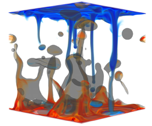
What causes the significant enhancement of heat transfer in the cases with oleophilic walls despite using only a small amount of oil? The major reason is related to the thermal plumes, which are the primary heat carrier in thermal turbulence (Ahlers et al. Reference Ahlers, Grossmann and Lohse2009; Lohse & Xia Reference Lohse and Xia2010; Chilla & Schumacher Reference Chilla and Schumacher2012; Shishkina Reference Shishkina2021). To show the effect of the thermal plumes, we visualize them in figure 3(a) for the oleophobic cases, and in figure 3(b) for the oleophilic cases. In the cases with oleophobic walls, the thermal plumes mainly stay outside the oil phase after travelling into the bulk. The reason is that surface tension prevents the entrainment of external fluid into the oil phase. The only way for the heat carried by plumes to be transported across the interface of the two immiscible fluids is via thermal diffusion, the effects of which, however, are sufficiently small at such high  ${Ra}$.

Figure 3. Visualization of temperature fields and the oil–water interface for  $\alpha =10\,\%$ at ${Ra}_o/{Ra}_w=4$ and ${Ra}_w=10^{8}$ with the (a) oleophobic and (b) oleophilic walls. The colour legend is red/blue for hot/cold plumes. The black lines represent the oil–water interface and oil is in colour yellow. With oleophobic walls (a), most thermal plumes travel in the water phase, whereas with oleophilic walls (b), they are carried by the oil phase. For the shown times of the snapshots, $t_{n+1}>t_n$ holds.
In the oleophobic cases, the thermal plumes are mainly exposed to the turbulent bulk. In contrast, in the oleophilic cases, the thermal plumes detach from the oil-rich boundary layer (figure 3b). At the same time, the oil–water interface not only keeps thermal plumes inside the oil phase, but also prevents the heat carried by plumes from being mixed into the turbulent bulk. As a result, most hot (cold) thermal plumes can travel to the opposite plate with little heat loss (gain) to the turbulent bulk, as they are thermally strongly coupled to the oil phase. As shown in figure 3(b), the oil carrying the hot plumes rises up in the shape of a column, then breaks up into drops, and eventually coalesces with the oil in the upper boundary layer. During this process, the oil builds up an ‘expressway’ to transfer the heat efficiently. Thus, the heat transfer in the oleophilic cases is always significantly enhanced up to the same value as in the system with  $100\,\%$ oil, and only a small amount of oil (larger than $\alpha _c$) is required due to the strong coupling of the oil and the thermal plumes.
To quantitatively confirm this physical picture, we measure the amount of thermal plumes, using as thermal plumes the definition condition  $|T- \langle T \rangle |>\sqrt {\langle (T-\langle T\rangle )^{2}\rangle }$, with $T({\boldsymbol x},t)$ being the local temperature and $\langle ~\rangle$ the spatial and temporal average. In figure 4, we show the volume fraction of the total thermal plumes in the domain, $\alpha _{plume}$, the ratio of thermal plumes in oil over the total thermal plumes, $\phi$, and the correlation coefficient, $r_{xy}=\sum (x-\bar {x})(y-\bar {y})/\sqrt {\sum (x-\bar {x})^{2}\sum (y-\bar {y})^{2}}$, between the distribution of thermal plumes ( $x$) and oil ( $y$) in the whole domain, where the overbar represents the spatial average and $r_{xy}$ ranges from $0$ (no correlation) to $1$ (perfect correlation).

Figure 4. Volume fraction of thermal plumes,  $\alpha _{plume}$, the ratio of thermal plumes in oil over the total thermal plumes, $\phi$, and the correlation coefficient, $r_{xy}$, with $x$ being the thermal plumes and $y$ the oil phase: (a) as a function of ${Ra}_o/{Ra}_w$ for $\alpha =10\,\%$, and (b) as a function of $\alpha$ at $({Ra}_w,{Ra}_o)=(10^{7},8\times 10^{7})$ and $({Ra}_w,{Ra}_o)=(10^{8},4 \times 10^{8})$. Symbols denote the same cases as in figure 2, and the line in (b) represents $\alpha _c=\alpha _{plume}$ (4.1).
For the oleophilic cases, for various  ${Ra}_o/{Ra}_w$ and fixed $\alpha =10\,\%$ (figure 4a), we observe $\phi =80\,\%\pm 5\,\%$ and $r_{xy}=0.75\pm 0.05$, whereas for the oleophobic cases, we always have $\phi <6\,\%$ and $r_{xy}<0.09$. This finding shows that, in the oleophilic cases, most thermal plumes indeed are strongly coupled to the oil, contrasting with the weak coupling in the oleophobic cases.
Finally, how does one determine the critical volume fraction of oil  $\alpha _c$ to achieve maximum heat transfer efficiency? In figure 4(b), we show the oleophilic cases at various $\alpha$ and fixed $({Ra}_w,{Ra}_o)=(10^{7},8\times 10^{7})$ and $(10^{8},4 \times 10^{8})$, and the critical condition for cases with ${Nu}$ smaller than or close to ${Nu}_o$,
 \begin{equation} \alpha_c=\alpha_{plume},\end{equation}
which agrees well with our numerical results. For  $\alpha <\alpha _{plume}$ (blue symbols in figure 4b), although oil and the thermal plumes are still well coupled ( $r_{xy}\approx 0.75$), there is not enough oil to generate all the plumes ( $\phi \approx 50\,\%$), leading to ${Nu}$ smaller than ${Nu}_o$ (figure 2b). On the other hand, for $\alpha >\alpha _{plume}$ (black symbols in figure 4b), the excess amount of oil does not contribute to generating additional thermal plumes, and thus the heat transfer enhancement levels off and ${Nu}$ remains close to ${Nu}_o$, as shown in figure 2(b). Therefore, $\alpha _c$ is clearly determined by the volume of thermal plumes in the domain.
5. Conclusions and outlook
We have shown a novel way to significantly enhance the heat flux in wall-bounded thermally driven turbulence, namely by adding an oil phase (even of relatively small volume fraction) to the water and at the same time using oleophilic walls. The heat transport enhancement is brought about by the newly found flow structure, where the thermal plumes are strongly coupled with the oil phase for cases with oleophilic walls. With the thermal plumes fully encapsulated inside the oil phase, the maximum enhancement can be obtained.
Our method and findings can easily and directly be applied and extended to other wall-bounded turbulent multiphase transport systems relevant in science and technology, way beyond thermal transport, namely to turbulent multiphase mass or momentum transfer, such as drag in pipe or channel flow of oil–water mixtures (Pal Reference Pal1993; Roccon, Zonta & Soldati Reference Roccon, Zonta and Soldati2021), or of bubbly flow (Lu, Fernandez & Tryggvason Reference Lu, Fernandez and Tryggvason2005; Sanders et al. Reference Sanders, Winkel, Dowling, Perlin and Ceccio2006; Ceccio Reference Ceccio2010; Elbing et al. Reference Elbing, Mäkiharju, Wiggins, Perlin, Dowling and Ceccio2013; Murai Reference Murai2014), and angular momentum transfer in turbulent multiphase Taylor–Couette flow (van den Berg et al. Reference van den Berg, van Gils, Lathrop and Lohse2007; Murai, Oiwa & Takeda Reference Murai, Oiwa and Takeda2008; van Gils et al. Reference van Gils, Narezo Guzman, Sun and Lohse2013; Srinivasan et al. Reference Srinivasan, Kleingartner, Gilbert, Cohen, Milne and McKinley2015; Hu et al. Reference Hu2017; Spandan, Verzicco & Lohse Reference Spandan, Verzicco and Lohse2018; Bakhuis et al. Reference Bakhuis, Ezeta, Bullee, Marin, Lohse, Sun and Huisman2021; Yi, Toschi & Sun Reference Yi, Toschi and Sun2021). The reason is that what we manipulate by the wall coating and the qualitative and quantitative choice of the two phases are the coherent structures of the turbulent multiphase flow, and these determine not only the heat transfer in turbulent flow, but also mass and momentum transfer and therefore the overall drag.
Supplementary movies
Supplementary movies are available at https://doi.org/10.1017/jfm.2021.1068.
Acknowledgements
We acknowledge PRACE for awarding us access to MareNostrum in Spain at the Barcelona Computing Center (BSC) under the project  $2020225335$ and $2020235589$. This work was also carried out on the national e-infrastructure of SURFsara, a subsidiary of SURF Cooperation, the collaborative ICT organization for Dutch education and research.
Funding
The work was financially supported by ERC-Advanced Grant under the project no.  $740479$.
Declaration of interests
The authors report no conflict of interest.


 Open access