


1. Introduction
With increased awareness of the adverse impact caused by  $\mathrm {NO}_{x}$ emissions on public health and the environment, gas turbines for power generation and aircraft propulsion are now operated under lean premixed combustion conditions (Lieuwen Reference Lieuwen2012). However, such lean premixed combustion systems are more susceptible to thermoacoustic instability, which often leads to operational problems such as an unstable flame, excessive vibration, and increased hazardous emissions (Zinn & Lieuwen Reference Zinn and Lieuwen2005). If the thermoacoustic amplitude is beyond the limit that the system can withstand, structural failure is likely to occur, increasing the maintenance costs and shortening the life of gas turbines (Poinsot Reference Poinsot2017). These problems necessitate the development of appropriate control strategies.
Existing control strategies fall generally into two categories (Candel Reference Candel2002; Huang & Yang Reference Huang and Yang2009): passive control and active control. In passive control, the aim is to strengthen the damping mechanisms or weaken the driving mechanisms, without the use of external energy. Examples include installing Helmholtz resonators (Zhao & Morgans Reference Zhao and Morgans2009) and optimizing the combustor geometry (Aguilar & Juniper Reference Aguilar and Juniper2020). Active control can be divided into open-loop and closed-loop forms. Closed-loop control uses sensors to instruct actuators via a feedback controller so as to manipulate the system into a desired state (Dowling & Morgans Reference Dowling and Morgans2005). Although proven in various combustors (Paschereit & Gutmark Reference Paschereit and Gutmark2002; Morgans & Stow Reference Morgans and Stow2007; Bothien, Moeck & Paschereit Reference Bothien, Moeck and Paschereit2008), closed-loop control requires precise sensor–actuator coordination via a feedback algorithm, which can be difficult to design for oscillations with multiple modes. By contrast, open-loop control is a simpler and more robust alternative. Previous studies have demonstrated the effectiveness of open-loop control in weakening period-1 thermoacoustic oscillations (McManus, Vandsburger & Bowman Reference McManus, Vandsburger and Bowman1990; Richards et al. Reference Richards, Thornton, Robey and Arellano2007; Bellows, Hreiz & Lieuwen Reference Bellows, Hreiz and Lieuwen2008; Ćosić et al. Reference Ćosić, Bobusch, Moeck and Paschereit2012), but whether it can work on more complex dynamics remains an open question.
1.1. Chaos in thermoacoustics
That question is important because recent studies have shown that thermoacoustic oscillations can be far more complex than period-1 alone (Juniper & Sujith Reference Juniper and Sujith2018). Such complex thermoacoustic oscillations can contain multiple incommensurate frequencies, broadband spectral peaks, and a time-dependent amplitude (Sujith & Unni Reference Sujith and Unni2021). As a fundamental class of complex behaviour, chaos is characterized by a highly sensitive dependence on the initial conditions and by an irregular geometry in phase space (Moon Reference Moon1987; Strogatz Reference Strogatz2018). In a chaotic system, two trajectories that are initially very close in phase space will diverge rapidly over time, eventually following totally different paths depending on the initial conditions (Thompson & Stewart Reference Thompson and Stewart2002). In early work, Keanini, Yu & Daily (Reference Keanini, Yu and Daily1989) reported the first experimental evidence of chaotic thermoacoustic oscillations in a ramjet and characterized the complex dynamics using phase space reconstruction and the correlation dimension. Over the next two decades, however, there were only a handful of reports of chaotic thermoacoustic oscillations (Sterling Reference Sterling1993; Fichera, Losenno & Pagano Reference Fichera, Losenno and Pagano2001; Lei & Turan Reference Lei and Turan2009). Recently, more evidence of chaos has emerged, aided by the application of dynamical systems theory to the analysis of unsteady combustion phenomena (Juniper & Sujith Reference Juniper and Sujith2018). For example, chaotic oscillations have been observed in various types of self-excited thermoacoustic systems, ranging from laminar to turbulent combustors and from premixed to diffusion flames (Gotoda et al. Reference Gotoda, Nikimoto, Miyano and Tachibana2011; Boudy et al. Reference Boudy, Durox, Schuller and Candel2012; Kabiraj et al. Reference Kabiraj, Saurabh, Karimi, Sailor, Mastorakos, Dowling and Paschereit2015; Orchini, Illingworth & Juniper Reference Orchini, Illingworth and Juniper2015; Guan, Murugesan & Li Reference Guan, Murugesan and Li2018; Guan et al. Reference Guan, Li, Ahn and Kim2019d; Huhn & Magri Reference Huhn and Magri2020; Sun et al. Reference Sun, Rao, Zhao, Wang, Sun and Sun2020; Wang et al. Reference Wang, Han, Song, Yang and Sung2021).
The route to chaos is an equally important feature that can help to explain how a chaotic attractor is born in a nonlinear dynamical system. There are three classic routes to chaos (Anishchenko et al. Reference Anishchenko, Astakhov, Neiman, Vadivasova and Schimansky-Geier2007): the period-doubling route, the Ruelle–Takens–Newhouse (RTN) route, and the intermittency route. Along the period-doubling route, a system becomes chaotic through a cascade of period-doubling bifurcations (Feigenbaum Reference Feigenbaum1978). This route has been established numerically in a Rijke tube model by varying the heater power (Subramanian et al. Reference Subramanian, Mariappan, Sujith and Wahi2010; Huhn & Magri Reference Huhn and Magri2020) and in a  $G$-equation flame model coupled with linear acoustics by varying the flame position (Kashinath, Waugh & Juniper Reference Kashinath, Waugh and Juniper2014). Along the RTN route, the system first transitions to an unstable quasiperiodic $\mathbb {T}^3$ torus through three successive Hopf bifurcations, and then becomes chaotic after the $\mathbb {T}^3$ torus breaks down (Newhouse, Ruelle & Takens Reference Newhouse, Ruelle and Takens1978). This route has been established both experimentally in a turbulent premixed combustor by varying the equivalence ratio (Kabiraj et al. Reference Kabiraj, Saurabh, Karimi, Sailor, Mastorakos, Dowling and Paschereit2015), and numerically in a ducted premixed flame by varying the flame position (Kashinath et al. Reference Kashinath, Waugh and Juniper2014; Orchini et al. Reference Orchini, Illingworth and Juniper2015). Along the intermittency route, as the system approaches the bifurcation point, the phase trajectory diverts from its regular orbit to a chaotic orbit, and then revisits its regular orbit after exhibiting a transient epoch of chaos. The chaotic behaviour lasts longer in time as the system approaches the bifurcation point. Eventually, the system transitions to sustained chaos after passing the bifurcation point (Pomeau & Manneville Reference Pomeau and Manneville1980). This route was recently established experimentally in a Rijke tube by varying the flame position (Guan, Gupta & Li Reference Guan, Gupta and Li2020).
1.2. Forced synchronization of chaos
Forced synchronization of chaos refers to a process whereby one (or more) self-excited chaotic oscillator(s) adjusts its motion in response to external forcing (Boccaletti et al. Reference Boccaletti, Kurths, Osipov, Valladares and Zhou2002b). In general, forced synchronization is of interest because the natural frequency of a self-excited oscillator can be shifted to the forcing frequency (e.g. a non-resonant frequency of the system) and the oscillator amplitude can be reduced simultaneously (e.g. via asynchronous quenching) (Pikovsky, Rosenblum & Kurths Reference Pikovsky, Rosenblum and Kurths2003). Forced synchronization of chaos has been observed in many prototypical chaotic systems, such as the Rössler attractor (Rosenblum, Pikovsky & Kurths Reference Rosenblum, Pikovsky and Kurths1996), the Lorenz attractor (Pikovsky et al. Reference Pikovsky, Rosenblum, Osipov and Kurths1997a; Park, Zaks & Kurths Reference Park, Zaks and Kurths1999), and the Anishchenko–Astakhov oscillator (Anishchenko et al. Reference Anishchenko, Vadivasova, Postnov and Safonova1992). It has also been observed in several experimental systems, such as plasma discharge tubes (Rosa et al. Reference Rosa, Pardo, Ticos, Walkenstein and Monti2000, Reference Rosa, Ticos, Pardo, Walkenstein, Monti and Kurths2003; Ticos et al. Reference Ticos, Rosa, Pardo, Walkenstein and Monti2000), electrochemical oscillators (Kiss & Hudson Reference Kiss and Hudson2001, Reference Kiss and Hudson2002), and lasers (Boccaletti et al. Reference Boccaletti, Allaria, Meucci and Arecchi2002a; Lin et al. Reference Lin, Kuo, Hsu, Jan, Han, Ho and Jiang2012). There are two main types of forced synchronization of chaos: (i) in chaos-destroying synchronization (CDS), chaos is completely destroyed and the phase difference between the oscillator and the forcing is a constant value; and (ii) in phase synchronization of chaos (PSC), the oscillator frequency is locked to the forcing frequency, and the phase difference between the oscillator and the forcing remains bounded, exhibiting a random walk type of motion, but chaos still exists (Rosenblum et al. Reference Rosenblum, Pikovsky and Kurths1996). In the synchronous regime, the motion of the synchronized oscillator is periodic for CDS, but chaotic for PSC. This is because the initially wildly diverging phase trajectories of the chaotic attractor are replaced by a periodic orbit in CDS, but are confined to a small region in PSC – because chaos still exists (Pikovsky et al. Reference Pikovsky, Rosenblum, Osipov and Kurths1997a; Park et al. Reference Park, Zaks and Kurths1999). In PSC, Pikovsky et al. (Reference Pikovsky, Zaks, Rosenblum, Osipov and Kurths1997b) showed that the phase-synchronized region of a chaotic oscillator is the overlap of all the phase-locked regions of the unstable periodic orbits (UPOs) embedded in that chaotic attractor. In other words, PSC occurs when all the UPOs are phase-locked to the external forcing.
In thermoacoustics, the forced synchronization of chaos has been studied less widely than that of periodic and quasiperiodic oscillations (Balusamy et al. Reference Balusamy, Li, Han, Juniper and Hochgreb2015; Guan et al. Reference Guan, Gupta, Kashinath and Li2019a,Reference Guan, Gupta, Wan and Lib; Mondal, Pawar & Sujith Reference Mondal, Pawar and Sujith2019; Sato et al. Reference Sato, Hyodo, Biwa and Delage2020; Aravind, Sankar & Lacoste Reference Aravind, Sankar and Lacoste2022; Passarelli et al. Reference Passarelli, Kazbekov, Salazar, Venkatesan and Steinberg2023). For the latter, a wide range of synchronization phenomena has been observed experimentally, including: (i) two different routes to synchronization, one via a saddle-node bifurcation and the other via an inverse Neimark–Sacker bifurcation; (ii) a region of  $1:1$ synchronization centred on the natural frequency (referred to as the $1:1$ Arnold tongue); and (iii) asynchronous quenching and resonant amplification when the forcing frequency is far from and close to the natural frequency, respectively. Crucially, these synchronization phenomena observed in experiments have been reproduced phenomenologically with low-order oscillator models. Such models are less computationally demanding than high-fidelity numerical simulations and can be deployed flexibly as surrogate models to understand and predict complex physical processes (Jaensch et al. Reference Jaensch, Merk, Gopalakrishnan, Bomberg, Emmert, Sujith and Polifke2017; Bonciolini & Noiray Reference Bonciolini and Noiray2019). This approach sets the stage for the development of quantitatively accurate models by leveraging the qualitative insights gained from low-order phenomenological modelling. However, the forced synchronization of chaotic thermoacoustic oscillations remains largely unexplored in both experiments and low-order modelling. Although Kashinath, Li & Juniper (Reference Kashinath, Li and Juniper2018) have demonstrated the stabilization of one of the UPOs of a chaotic attractor in a confined premixed flame model using external periodic forcing at the dominant natural frequency, the synchronization dynamics in the overall parameter space and the optimal actuation strategy remain unclear.
1.3. Chaos control
Chaos control refers to a process whereby a specific behaviour is induced in a chaotic system by perturbing it deliberately (Boccaletti et al. Reference Boccaletti, Grebogi, Lai, Mancini and Maza2000). Ott, Grebogi & Yorke (Reference Ott, Grebogi and Yorke1990) first proposed a chaos control strategy whereby one of the infinite number of UPOs of a chaotic attractor is stabilized by the application of a judiciously chosen small transient perturbation. Since its discovery, this control strategy has been demonstrated successfully on various experimental systems, such as magnetoelastic ribbons (Ditto, Rauseo & Spano Reference Ditto, Rauseo and Spano1990) and cardiac arrhythmias (Garfinkel et al. Reference Garfinkel, Spano, Ditto and Weiss1992). However, without sufficient prior knowledge of the system properties and with incomplete measurements of the system itself, it can be difficult to implement this control strategy in practice (Fradkov & Evans Reference Fradkov and Evans2005). Furthermore, the strategy is suitable only for slowly oscillating systems because applying a judiciously chosen transient perturbation is feasible only when the system time scales are sufficiently long (Kociuba, Heckenberg & White Reference Kociuba, Heckenberg and White2001). By contrast, the open-loop control of chaos via the application of periodic perturbations can be a simpler alternative: the perturbations are applied continuously, without requiring real-time measurements of the system, thus making the control of rapidly oscillating systems possible (Fradkov & Evans Reference Fradkov and Evans2005). Such a chaos control strategy has found success in a variety of theoretical and experimental systems, such as the Duffing–Holmes oscillator (Lima & Pettini Reference Lima and Pettini1990), a periodically driven pendulum (Braiman & Goldhirsch Reference Braiman and Goldhirsch1991), a bistable magnetoelastic beam (Fronzoni, Giocondo & Pettini Reference Fronzoni, Giocondo and Pettini1991), a  $\rm {CO_2}$ laser (Meucci et al. Reference Meucci, Gadomski, Ciofini and Arecchi1994), and discharge plasma (Ding et al. Reference Ding, She, Huang and Yu1994). As one can see, the forced synchronization of chaos and the open-loop control of chaos are based on similar mechanisms: a chaotic system is forced externally and continuously such that one of its UPOs becomes stable (Ditto & Showalter Reference Ditto and Showalter1997; Kurths et al. Reference Kurths, Boccaletti, Grebogi and Lai2003). This commonality justifies our use of a forced synchronization framework to study the open-loop control of chaotic thermoacoustic oscillations.
1.4. Contributions of the present study
In this study, we investigate the forced synchronization of chaotic thermoacoustic oscillations, with the aim of answering three research questions.
(i) A variety of forced synchronization dynamics has been reported in recent studies of periodic and quasiperiodic thermoacoustic systems subjected to external forcing. What forced synchronization dynamics does a chaotic thermoacoustic system show?
(ii) Open-loop periodic acoustic forcing is known to be able to weaken both periodic and quasiperiodic thermoacoustic oscillations. Can it also weaken chaotic thermoacoustic oscillations? If so, what is the optimal forcing strategy to reduce the thermoacoustic amplitude? How does this forcing strategy differ from that used for periodic and quasiperiodic thermoacoustic oscillations?
(iii) Can a low-order model phenomenologically reproduce the experimental synchronization dynamics and the changes in thermoacoustic amplitude revealed by answering the first two questions?
To answer these questions, we systematically test a wide range of forcing frequencies and amplitudes on a prototypical combustion system (§ 2) capable of hosting self-excited chaotic thermoacoustic oscillations, as reported by Guan et al. (Reference Guan, Gupta and Li2020). We measure the acoustic pressure and heat-release-rate response of the forced system, and analyse the data within a forced synchronization framework (§ 3). We then use a low-order model to phenomenologically reproduce the experimentally observed dynamics, including the changes in thermoacoustic amplitude (§ 4). Finally, we conclude this paper by discussing the limitations and practical implications of our findings (§ 5).
2. Experimental set-up and data analysis
The experimental set-up (figure 1) used in this study is identical to that of our recent studies on synchronization and system identification (Guan et al. Reference Guan, Gupta, Kashinath and Li2019a,Reference Guan, Gupta, Wan and Lib,Reference Guan, He, Murugesan, Li, Liu and Lic; Lee et al. Reference Lee, Guan, Gupta and Li2020). The operating conditions are identical to those used by Guan et al. (Reference Guan, Gupta and Li2020): an equivalence ratio of 0.44 ( $\pm$3.2 %) and a bulk reactant velocity of 1.4 m s $^{-1}$ ( $\pm$0.2 %). Under these operating conditions, the system exhibits period-1 limit cycles, quasiperiodicity, intermittency and chaos, as the bifurcation parameter – the non-dimensional flame position $\tilde {z}$ – increases. Here, $\tilde {z} \equiv z/L$, where $z$ is the distance from the burner exit to the bottom of the tube combustor, and $L$ is the length of the tube combustor itself. We choose to force the chaotic thermoacoustic oscillator at $\tilde {z} = 0.122$ (characterized in § 3 of Guan et al. Reference Guan, Gupta and Li2020) because at this position, the highly unsteady chaotic flame is not blown off easily by the applied forcing. This facilitates the exploration of the synchronization dynamics over a wide range of forcing frequencies ( $0.70 \leq f_f / f_1 \leq 1.40$, $0.53 \leq f_f / f_2 \leq 1.06$) and forcing amplitudes (up to $\epsilon _f = 0.6$). Here, $f_1$ and $f_2$ are the two dominant natural frequencies of the chaotic thermoacoustic oscillator, and $f_f$ is the frequency of the sinusoidal forcing signal fed into a loudspeaker. The forcing amplitude is defined as $\epsilon _f \equiv u^\prime /\bar {u}$, where $u^\prime$ is the amplitude of the velocity perturbations, and $\bar {u}$ is the time-averaged velocity, both measured at the burner exit with a constant-temperature hot wire. The forced response of the system is measured in two different ways: (i) via the acoustic pressure fluctuations ( $\kern 0.06em p^\prime (t)$) using two probe microphones (GRAS 40SA, ${\pm }2.5 \times 10^{-5}$ Pa) mounted 43 mm (PM-1) and 387 mm (PM-2) from the bottom of the combustor; and (ii) via the CH $^*$ flame chemiluminescence emission ( $q^\prime (t)$) using a photomultiplier tube (Thorlabs PMM01) equipped with a bandpass optical filter centred on 430 nm. In this study, we use only the pressure signal from PM-2 because it shows roughly the same dynamics as the signal from PM-1 but with a higher signal-to-noise ratio. To supplement the $p^\prime (t)$ and $q^\prime (t)$ signals, we capture time-resolved flame images with a high-speed camera (HSC: Photron FASTCAM SA-Z) operating at 4000 Hz, with an image resolution of $256 \times 512$ pixels and a bit depth of 12.

Figure 1. Schematic diagram of the experimental set-up, which is identical to that used in our recent studies on synchronization and system identification (Guan et al. Reference Guan, Gupta, Kashinath and Li2019a,Reference Guan, Gupta, Wan and Lib,Reference Guan, He, Murugesan, Li, Liu and Lic; Lee et al. Reference Lee, Guan, Gupta and Li2020).
The  $p^\prime (t)$ and $q^\prime (t)$ signals are digitized at 16 384 Hz for 6 s using a 16-bit data converter (DAQ: NI USB-6356). We process both signals using the same methods and parameters as in Guan et al. (Reference Guan, Gupta and Li2020). Time–frequency analysis is performed via the short-time Fourier transform, and frequency analysis is performed by computing the power spectral density (PSD) via the Welch (Reference Welch1967) algorithm. We compute the instantaneous phase of a signal using the Hilbert transform (Gabor Reference Gabor1946), and then determine the instantaneous phase difference between two given signals (Li & Juniper Reference Li and Juniper2013a): $\Delta \psi _{x,y} \equiv \psi _{x} - \psi _{y}$ (e.g. $\Delta \psi _{p^\prime,q^\prime } \equiv \psi _{p^\prime } - \psi _{q^\prime }$). To characterize the nonlinear dynamics, we use phase space reconstruction, the correlation dimension, the permutation spectrum test, the 0–1 test, and the filtered horizontal visibility graph. These techniques are described in Appendix A.
3. Experimental results and discussion
3.1. Unforced chaotic thermoacoustic oscillator
We previously established the existence of chaos in this system by analysing the  $p^\prime (t)$ signal (see § 3 of Guan et al. Reference Guan, Gupta and Li2020). In this subsection, we supplement that evidence by analysing the $q^\prime (t)$ signal as well, providing a more complete characterization of the unforced chaotic attractor. This attractor is generated via the intermittency route to chaos as the flame position ( $\tilde {z}$) is varied, with the other operating parameters held constant. One of the natural frequencies, $f_1$, is generated via a Hopf bifurcation at $\tilde {z} = 0.034$, where the system transitions from a fixed point to a limit cycle. Another natural frequency, $f_2$, is generated via a torus-birth bifurcation at $\tilde {z} = 0.099$, where the system transitions from the limit cycle to a two-frequency quasiperiodic (torus) attractor. After passing through a type-II intermittent regime ( $0.105 \leq \tilde {z} < 0.122$), the system eventually becomes chaotic. For details about the birth of this chaotic attractor, please see Guan et al. (Reference Guan, Gupta and Li2020). In figure 2, we characterize both the $p^\prime$ (blue) and $q^\prime$ (black) signals from this unforced chaotic oscillator ( $\rm {CH}_{1,2}$). Both signals are normalized by their respective root mean square (r.m.s.) values without forcing: $\tilde {p}^\prime \equiv {p}^\prime /{p}^\prime _{0,rms}$ and $\tilde {q}^\prime \equiv {q}^\prime /{q}^\prime _{0,rms}$. Both signals feature irregular waveforms with temporal amplitude variations and occasional high-amplitude bursts (figure 2a), which are the classic signatures of a chaotic time series. The spectrogram and PSD show a broadband peak at $f_1 = 171\pm 10$ Hz with a temporally varying intensity (figures 2b i,ii), which is again indicative of a chaotic time series. Moreover, we find two intermittent spectral peaks: $f_2 = 210\pm 5$ Hz and $f_3 = 228\pm 8$ Hz. The $f_2$ peak is narrower and weaker than the $f_1$ peak, but both peaks often coexist in both the $p^\prime (t)$ and $q^\prime (t)$ signals, indicating that both $f_1$ and $f_2$ are thermoacoustic modes. The $f_3$ peak emerges strongly near the $f_2$ peak, but only in the $p^\prime (t)$ spectrum (not the $q^\prime (t)$ spectrum), implying that $f_3$ is a pure acoustic mode, i.e. it is not due to flame–acoustic feedback. The emergence of this $f_3$ mode produces a large drop in $\tilde {q}^\prime (t)$ (grey shading in figure 2a). Because a chaotic oscillator cannot be replicated exactly every time owing to its exceptional sensitivity to the initial conditions, we show in figures 2(c i–iii) histograms of the normalized amplitudes, $p^\prime /p^\prime _{max}$ and $q^\prime /q^\prime _{max}$, and of the wrapped phase difference between $p^\prime (t)$ and $q^\prime (t)$, denoted as $\Delta \psi _{p^\prime, q^\prime }$. In each plot, the solid lines and surrounding shading represent the mean and standard deviation ( $\sigma$), respectively. This is done to highlight their statistical similarities, i.e. the base oscillator generated for each test case can be treated as the same oscillator in this study. It can be concluded that none of the statistical properties of the unforced chaotic oscillator show significant differences – except for very small-scale fluctuations of order ${\pm }0.1$ for both ${p}^\prime /{p}^\prime _{max}$ and ${q}^\prime /{q}^\prime _{max}$. It is worth noting that neither signal obeys a Gaussian distribution in our laminar system, which is unlike the high-dimensional chaotic combustion noise observed by Nair & Sujith (Reference Nair and Sujith2014) in a turbulent system. The core of the $\Delta \psi _{p^\prime, q^\prime }$ distribution resides in the in-phase regime (dark grey shading in figure 2c iii), implying that the Rayleigh criterion is met (Magri, Juniper & Moeck Reference Magri, Juniper and Moeck2020; Schuermans et al. Reference Schuermans, Moeck, Blondé, Dharmaputra and Noiray2023). Further analysis of this low-dimensional chaotic state is presented in Appendix A via the permutation spectrum test, the 0–1 test, the correlation dimension, and the filtered horizontal visibility graph.

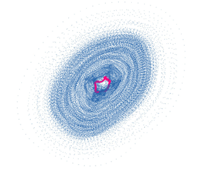
Figure 2. Unforced chaotic dynamics in both the  ${p}^\prime (t)$ and ${q}^\prime (t)$ signals: (a) time trace, (b) spectrogram and PSD, (c) histograms of the normalized amplitudes and of the wrapped phase difference between ${p}^\prime (t)$ and ${q}^\prime (t)$, denoted as $\Delta \psi _{{p}^\prime,{q}^\prime }$. The ${p}^\prime (t)$ and ${q}^\prime (t)$ signals are shown in blue and black, respectively. Here, $\tilde {p}^\prime \equiv {p}^\prime /{p}^\prime _{0,rms}$, where ${p}^\prime _{0,rms}$ is the r.m.s. of $p^\prime (t)$ without forcing; $\tilde {q}^\prime$ is defined similarly.
3.2. Forced synchronization of a chaotic thermoacoustic oscillator
We examine the forced synchronization of the chaotic thermoacoustic oscillator from § 3.1 across a wide range of forcing frequencies ( $0.70 \leq f_f / f_1 \leq 1.40$ and $0.53 \leq f_f / f_2 \leq 1.06$) and forcing amplitudes ( $0.0 \leq \epsilon _f \leq 0.6$).
3.2.1. Dynamical states
We start by presenting a map of the dynamical states in figure 3(a). The overall parameter space can be divided into two regions based on whether CDS occurs.

Figure 3. Overview of the forced synchronization dynamics: (a) dynamical states, (b) 0–1 test metric  $K$, (c) normalized thermoacoustic amplitude $\eta _{p^\prime }$, and (d) proximity map for all the forced and unforced cases. In (a–c), the grey background denotes flame blow-off (FBO). In (d), the colour bar denotes the cost function $J$.
$J$.
In the first region ( $0.70 \leq f_f / f_1 \leq 1.15$ and $0.53 \leq f_f / f_2 \leq 0.87$), CDS occurs when $\epsilon _f$ exceeds a critical value, with the system following two routes to synchronization. Along the first route, unforced self-excited chaos ( ${\rm {CH}}_{1,2}$, blue) $\rightarrow$ forced chaos ( ${\rm {CH}}_{1,2,f}$, green) $\rightarrow$ single torus ( ${\mathbb {T}}^2_{2,f}$, purple) $\rightarrow$ period-1 orbit ( ${\rm {P1}}_f$, magenta). This route occurs in the range $0.82 \leq f_f / f_1 \leq 1.15$ ( $0.62 \leq f_f / f_2 \leq 0.87$) and ends with $f_f : f_1 = 1:1$ CDS before flame blow-off (FBO) or a transition out of the period-1 state and into a new chaotic state ( ${\rm {CH}}_{3,f}$) at higher $\epsilon _f$. Along the second route, unforced self-excited chaos ( ${\rm {CH}}_{1,2}$, blue) $\rightarrow$ forced chaos ( ${\rm {CH}}_{1,2,f}$, green) $\rightarrow$ doubled torus ( ${2\mathbb {T}}^2_{2,f}$, pink) $\rightarrow$ period-2 orbit ( ${\rm {P2}}_f$, dark red). This route occurs in the range $0.70 \leq f_f / f_1 \leq 0.82$ ( $0.53 \leq f_f / f_2 \leq 0.62$) and ends with $f_f : f_1 = 2:1$ CDS before FBO or a transition out of the period-2 state and into a new chaotic state ( ${\rm {CH}}_{3,f}$) at higher $\epsilon _f$. For both routes, the new chaotic state above the synchronization regime has a pure acoustic mode at $f_3$ (§ 3.1) and a forced mode at $f_f$. Moreover, FBO occurs when $\epsilon _f$ is high (i.e. grey shading in figure 3a).
In the second region ( $1.15 \leq f_f / f_1 \leq 1.40$ and $0.87 \leq f_f / f_2 \leq 1.06$), chaos is not destroyed by the forcing even when $\epsilon _f$ is exceedingly high (0.60), approximately nine times greater than the average critical forcing amplitude required for CDS. However, PSC occurs when $\epsilon _f$ exceeds a critical value. This phase-synchronized state (PSC, dark green) is chaotic, and the phase difference no longer drifts in time but becomes bounded. The flame is eventually blown off (FBO) by the strong forcing when $\epsilon _f$ exceeds a critical value.
3.2.2. Chaos map
In figure 3(b), we map the regions where chaotic dynamics dominates using the 0–1 test, which can be viewed as a method for extracting a binary quantity from the power spectrum (Gottwald & Melbourne Reference Gottwald and Melbourne2009). When  $\epsilon _f$ is zero or small, the 0–1 test metric $K$ is approximately 1, indicating chaotic dynamics corresponding to the unforced base state ( ${\rm {CH}}_{1,2}$) or the states with small $\epsilon _f$ ( ${\rm {CH}}_{1,2,f}$). When $\epsilon _f$ is moderate, $K$ falls below 0.5, indicating non-chaotic dynamics corresponding to the single and doubled torus attractors ( ${\mathbb {T}}^2_{2,f}$ and ${2\mathbb {T}}^2_{2,f}$). When $\epsilon _f$ reaches a critical value, $K$ approaches 0, indicating non-chaotic dynamics corresponding to the periodic states ( ${\rm {P1}}_f$ and ${\rm {P2}}_f$) arising after chaos is destroyed by CDS. When $\epsilon _f$ exceeds the critical value, $K$ returns to 1 before FBO. This indicates that the system is again dominated by chaotic dynamics, which corresponds to the forced chaotic state ( ${\rm {CH}}_{3,f}$). In summary, the 0–1 test qualitatively delineates the chaotic and non-chaotic regimes, which are consistent with the dynamical states mapped out in figure 3(a). This confirms the existence of chaos in some of the forced dynamical states.
3.2.3. Thermoacoustic amplitude
In figure 3(c), we examine the changes in thermoacoustic amplitude brought on by the forcing. The normalized thermoacoustic amplitude is defined as  $\eta _{p^\prime } \equiv (\sigma ^\ast _{p^\prime } - \sigma _{p^\prime })/\sigma _{p^\prime }$, where $\sigma ^\ast _{p^\prime }$ and $\sigma _{p^\prime }$ are the r.m.s. of $p^\prime (t)$ when the chaotic oscillator is forced and unforced, respectively. Thus, the forcing weakens the thermoacoustic oscillations when $\eta _{p^\prime } < 0$ (blue) but amplifies them when $\eta _{p^\prime } > 0$ (red). We note the following features in figure 3(c):
(i) Amplitude reduction ( $\eta _{p^\prime } < 0$) occurs not only when $f_f$ is an off-resonant frequency of $f_1$ but also when it is in the vicinity of $f_1$. As in previous studies (Bellows et al. Reference Bellows, Hreiz and Lieuwen2008; Ćosić et al. Reference Ćosić, Bobusch, Moeck and Paschereit2012; Guan et al. Reference Guan, Gupta, Kashinath and Li2019a,Reference Guan, Gupta, Wan and Lib; Mondal et al. Reference Mondal, Pawar and Sujith2019), applying forcing at an off-resonant frequency can induce asynchronous quenching without triggering resonant amplification near the natural mode, thus reducing the total energy of the oscillations. However, in this study, $\eta _{p^\prime }$ is also reduced by synchronous quenching (Odajima, Nishida & Hatta Reference Odajima, Nishida and Hatta1974), and the resonant amplification near $f_1$ is weak. Thus, amplitude reduction ($\eta _{p^\prime } < 0$) still occurs when $f_f$ is near $f_1$. In § 3.4, we will show more details about synchronous and asynchronous quenching as well as resonant amplification.
(ii) The thermoacoustic amplitude increases gradually as
$\epsilon _f$ increases after the onset of CDS, implying that the optimal forcing amplitude for a given forcing frequency is that which just enables the onset of CDS. This concurs with previous studies (Guan et al. Reference Guan, Gupta, Kashinath and Li2019a,Reference Guan, Gupta, Wan and Lib; Mondal et al. Reference Mondal, Pawar and Sujith2019), where the optimal forcing amplitude was found to be the critical (minimum) value required for the onset of synchronization.(iii) The thermoacoustic amplitude increases markedly owing to the occurrence of resonant amplification near the weaker thermoacoustic mode
$f_2$. This is unlike previous studies (Guan et al. Reference Guan, Gupta, Kashinath and Li2019a,Reference Guan, Gupta, Wan and Lib; Mondal et al. Reference Mondal, Pawar and Sujith2019), where resonant amplification tends to occur near the dominant natural mode.(iv) The critical forcing amplitude varies only slightly across different forcing frequencies, resulting in a flat CDS boundary, rather than a characteristic
$\vee$ shape around the natural frequency. The latter behaviour is observed typically in the forced synchronization of periodic and quasiperiodic systems (Guan et al. Reference Guan, Gupta, Kashinath and Li2019a,Reference Guan, Gupta, Wan and Lib; Mondal et al. Reference Mondal, Pawar and Sujith2019).


3.2.4. Proximity map
Figure 3(d) shows the proximity map for all the forced and unforced cases examined in figures 3(a–c). This map enables these cases to be compared in terms of the control efficacy and actuation cost. The construction algorithm is described in Appendix B.
Figure 3(d) shows that the cases with a small value of the cost function ( $J<1$) tend to cluster together, whereas those with intermediate $J$ (
$J$ ( $= 1$) are more scattered but still confined to a relatively small part of the feature space. By contrast, the cases with large $J$ (
$J$ ( $>1$) are more scattered, stretching over three different arcs in the feature space. This implies that the cases with small $J$ have similar forced responses in ${p}^\prime$ and ${q}^\prime$, requiring approximately the same forcing amplitudes to achieve the same thermoacoustic amplitude reductions even across different $f_f$ values. In other words, the control efficiency is largely insensitive to the forcing frequency when $f_f / f_1 \leq 1.15$, which contrasts with previous studies where the results are strongly dependent on $f_f$. Nevertheless, our findings are consistent with the forced response map shown in figure 3(c), where the boundary for thermoacoustic amplitude reduction does not change significantly across different values of $f_f$.
In summary, we have shown that: (i)  $1:1$ and $2:1$ CDS occurs when $f_f/f_1 \leq 1.15$; (ii) PSC occurs when $f_f/f_1 > 1.15$; (iii) chaos arises again from a phase-locked limit cycle when $\epsilon _f$ is sufficiently high; (iv) the thermoacoustic oscillations can be weakened via asynchronous and synchronous quenching; (v) resonant amplification occurs at approximately $f_2$; and (vi) the control efficiency is largely insensitive to the forcing frequency when $f_f / f_1 \leq 1.15$, preventing the formation of a characteristic $\vee$-shaped synchronization boundary. In the next subsection, we provide more details about the system dynamics en route to CDS and beyond.
3.3. Route to chaos-destroying synchronization
We examine the forced response of the system en route to  $1:1$ and $2:1$ CDS and PSC as $\epsilon _f$ increases at a fixed $f_f/f_1$. Figures 4, 6 and 7 show the results from both the $p^\prime$ and $q^\prime$ signals: (a) time traces of the normalized amplitudes, (b) PSDs, (c,d) phase portraits, (e) Poincaré maps, (f) instantaneous phase differences ( $\Delta \psi _{p^\prime,q^\prime }$, $\Delta \psi _{p^\prime,f}$, $\Delta \psi _{q^\prime,f}$), and (g) histograms of the wrapped phase differences ( $\zeta _{p^\prime,q^\prime }$, $\zeta _{p^\prime,f}$, $\zeta _{q^\prime,f}$). Each figure is for five values of $\epsilon _f$, beginning with $\epsilon _f = 0$ (unforced) at the bottom row.

Figure 4. Route to  $1:1$ CDS in a chaotic thermoacoustic oscillator forced at $f_f /f_1 = 1.01$ ( $\,f_f/f_2 = 0.76$): (a) normalized time traces, (b) PSD, (c,d) phase portraits, (e) Poincaré maps, (f) instantaneous phase differences ( $\Delta \psi _{p^\prime,q^\prime }$, $\Delta \psi _{p^\prime,f}$, $\Delta \psi _{q^\prime,f}$), and (g) histograms of the wrapped phase differences ( $\zeta _{p^\prime,q^\prime }$, $\zeta _{p^\prime,f}$, $\zeta _{q^\prime,f}$). The forcing amplitude, listed on the far right, is $\epsilon _f = 0$ for the bottom row (unforced) and increases to the top row. The $p^\prime (t)$ data are shown in different colours based on the specific dynamical state, while the $q^\prime (t)$ data are always shown in black. In (f,g), the light and dark grey shading denote anti-phase and in-phase motion, respectively.
3.3.1. The $1:1$ chaos-destroying synchronization

In figure 4, we examine the route to  $1:1$ CDS at $f_f/f_1 = 1.01$ ( $\,f_f/f_2 = 0.76$). Sequences of time-resolved flame images are shown in figure 5 to supplement the scalar data shown in figure 4. As $\epsilon _f$ increases, we find that the system exhibits a wide range of forced synchronization dynamics.
(i) When unforced (
$\epsilon _f = 0$), the system is chaotic (${\rm {CH}}_{1,2}$) with two natural modes ($\,f_1$ and $f_2$). In figure 2, similar chaotic behaviour was observed in both the time and frequency domains. As forcing is not yet applied, only $\Delta \psi _{p^\prime,q^\prime }$ and $\zeta _{p^\prime,q^\prime }$ are shown. While $\Delta \psi _{p^\prime,q^\prime }$ drifts unboundedly in time, several in-phase synchronous epochs appear intermittently (see the inset in figure 4f v). Moreover, $\zeta _{p^\prime,q^\prime }$ shows a tight unimodal distribution. Put together, these observations indicate the presence of intermittent frequency locking between $p^\prime$ and $q^\prime$. Unlike the intermittent frequency locking reported by Pawar et al. (Reference Pawar, Seshadri, Unni and Sujith2017) and Guan et al. (Reference Guan, Li, Jegal and Kim2022a,Reference Guan, Moon, Kim and Lib), here the intermittent relationship occurs between two chaotic signals, with switching between frequency-locked chaos and desynchronization. As discussed in § 3.1, the majority of $\zeta _{p^\prime,q^\prime }$ resides in the in-phase regime (dark grey shading), implying that the Rayleigh criterion is met (Magri et al. Reference Magri, Juniper and Moeck2020; Schuermans et al. Reference Schuermans, Moeck, Blondé, Dharmaputra and Noiray2023). Figure 5(e) shows a sequence of time-resolved flame images for this unforced chaotic state (${\rm {CH}}_{1,2}$). We highlight in yellow text five images equispaced in time: $t_1$, $t_{24}$, $t_{47}$, $t_{70}$ and $t_{93}$. If the flame were oscillating periodically at its dominant frequency of $f_1 = 171$ Hz, then the image sequence (recorded at 4000 Hz) would repeat itself every 23 frames. However, the flame fronts at these five time instants are seen to be quite different from each other, ruling out periodicity. Compared with the flame fronts in periodic (Guan et al. Reference Guan, He, Murugesan, Li, Liu and Li2019c) and quasiperiodic (Guan et al. Reference Guan, Gupta, Wan and Li2019b) systems, the flame fronts in this chaotic system are more asymmetric, with a clear rightward lean and a weaker right flame root. However, the leaning direction is not always to the right; we will show later that for ${\rm {CH}}_{3,f}$, the leaning direction can change seemingly randomly. These asymmetries are believed to arise from spatial variations in the local entrainment and flame anchoring characteristics around the burner lip, possibly due to imperfect machining. The effects of these variations are relatively minor when the thermoacoustic oscillations are regular, but become amplified when the degree of chaos increases. Flame roll-up wrinkles and pinch-off can also be observed, but the modulation of the flame fronts is irregular, causing the number and curvature of the flame wrinkles to vary from cycle to cycle.(ii) When forced at a low amplitude (
$\epsilon _f = 0.021$), the system transitions to a forced chaotic state (${\rm {CH}}_{1,2,f}$) with two natural modes ($\,f_1$ and $f_2$) and a forced mode ($\,f_f$). The time traces show irregular time-dependent amplitude modulations, and the PSD plots show two broadband peaks at $f_1$ and $f_2$, indicating the dominance of chaotic dynamics in both the time and frequency domains. The phase portraits and double-sided Poincaré maps show an irregular structure, consistent with the presence of a chaotic attractor. All three instantaneous phase differences ($\Delta \psi _{p^\prime,q^\prime }$, $\Delta \psi _{p^\prime,f}$, $\Delta \psi _{q^\prime,f}$) drift unboundedly in time, but with finite constant epochs appearing simultaneously (e.g. at approximately $t=1$–$3$ s). Meanwhile, only $\zeta _{p^\prime,q^\prime }$ shows a tight unimodal distribution, with both $\zeta _{p^\prime,f}$ and $\zeta _{q^\prime,f}$ showing uniform distributions. Put together, these observations indicate that intermittent frequency locking occurs between $p^\prime$ and $q^\prime$, while desynchronization occurs for the other two pairs of signals. Figure 5(d) shows a sequence of time-resolved flame images for this forced chaotic state (${\rm {CH}}_{1,2,f}$). We again highlight in yellow text five equispaced time instants: $t_1$, $t_{24}$, $t_{47}$, $t_{70}$ and $t_{93}$. We do not observe any regular repetition of the flame fronts, consistent with the aperiodic nature of this state. The flame-front characteristics of this forced chaotic state are broadly similar to those of the unforced chaotic state examined earlier (${\rm {CH}}_{1,2}$). This is expected as the dynamics of the $q^\prime$ signal is approximately the same for these two chaotic states.(iii) When forced at a moderate amplitude (
$\epsilon _f = 0.041$), the system transitions to a two-frequency quasiperiodic state ($\mathbb {T}^2_{2,f}$) with two incommensurate modes ($\,f_2$ and $f_f$). The $f_1$ mode is suppressed by the forcing. The time traces show regular amplitude modulations, and the PSD plots show sharp peaks at $f_2$ and $f_f$ as well as at their linear combinations, indicating the dominance of quasiperiodic dynamics. The phase portraits and single-sided Poincaré maps show a doughnut-like structure and a hollow ring pattern, respectively, indicating the presence of a torus attractor. All three instantaneous phase differences ($\Delta \psi _{p^\prime,q^\prime }$, $\Delta \psi _{p^\prime,f}$, $\Delta \psi _{q^\prime,f}$) drift unboundedly in time, and their histograms ($\zeta _{p^\prime,q^\prime }$, $\zeta _{p^\prime,f}$, $\zeta _{q^\prime,f}$) show uniform distributions, indicating that the three pairs of signals are not synchronous. Figure 5(c) shows a sequence of time-resolved flame images for this two-frequency quasiperiodic state ($\mathbb {T}^2_{2,f}$). We highlight in yellow text three equispaced time instants: $t_{10}$, $t_{33}$ and $t_{56}$. Compared with the markedly different flame fronts seen in the chaotic states (${\rm {CH}}_{1,2}$ and ${\rm {CH}}_{1,2,f}$), here the flame fronts appear more similar from cycle to cycle, although they are still not repetitive. This is consistent with the fact that a quasiperiodic system evolves with a period of infinity, so it never repeats itself exactly but can come arbitrarily close (Hilborn Reference Hilborn2000).(iv) When forced at a critical amplitude (
$\epsilon _f = 0.052$), the system transitions to a phase-locked limit cycle (${\rm {P1}}_f$) with a suppression of the remaining natural mode ($\,f_2$). The time traces show periodic oscillations, and the PSD plots show only a single sharp peak at $f_f$, indicating the dominance of periodic dynamics in both the time and frequency domains. The phase portraits and single-sided Poincaré maps show a closed orbit and a distinct group of intercepts, respectively, indicating the presence of a limit cycle in phase space. Both $\Delta \psi _{p^\prime,q^\prime }$ and $\Delta \psi _{p^\prime,f}$ are bounded in the anti-phase regime (light grey shading), while $\Delta \psi _{q^\prime,f}$ is bounded in the in-phase regime (dark grey shading). Put together, these observations reveal that the system has locked into the periodic forcing, with no sign of chaos, consistent with CDS (Pikovsky et al. Reference Pikovsky, Rosenblum and Kurths2003). We also find a significant reduction in the pressure amplitude, demonstrating that open-loop periodic acoustic forcing can effectively weaken chaotic thermoacoustic oscillations. Figure 5(b) shows a sequence of time-resolved flame images for this phase-locked limit cycle (${\rm {P1}}_f$). We highlight in yellow text three equispaced time instants: $t_{1}$, $t_{24}$ and $t_{47}$. The flame front repeats exactly at these three chosen time instants, providing further confirmation of limit-cycle dynamics.(v) When forced at a high amplitude (
$\epsilon _f = 0.098$), the system transitions from ${\rm {P1}}_f$ to another forced chaotic state (${\rm {CH}}_{3,f}$) with a new dominant natural mode ($\,f_3$). The time traces and PSD plots resemble those seen in the previous chaotic states. However, because the $f_3$ mode is purely acoustic, its spectral peak is present only in the PSD of $p^\prime (t)$ and not in that of $q^\prime (t)$. Furthermore, the PSD background level is significantly higher (35 dB Hz$^{-1}$) than that of ${\rm {P1}}_f$. The phase portraits and double-sided Poincaré maps show a complex object and two irregular blobs, respectively, confirming the presence of a chaotic attractor. Although $\Delta \psi _{p^\prime,f}$ drifts relatively slowly with several anti-phase epochs, both $\Delta \psi _{p^\prime,q^\prime }$ and $\Delta \psi _{q^\prime,f}$ drift unboundedly in time. Moreover, $\zeta _{p^\prime,f}$ has a higher peak than both $\zeta _{p^\prime,q^\prime }$ and $\zeta _{q^\prime,f}$. This indicates that $p^\prime (t)$ and the forcing signal undergo intermittent frequency locking, while the other two pairs of signals are asynchronous. With chaos re-emerging in the system, the phase dynamics indicates that the chaotic attractor is intermittently entrained by the external forcing. Figure 5(a) shows a sequence of time-resolved flame images for this forced chaotic state (${\rm {CH}}_{3,f}$). We highlight in yellow text five equispaced time instants: $t_1$, $t_{24}$, $t_{47}$, $t_{70}$ and $t_{93}$. The flame fronts at these five instants are quite different from each other, but are again dominated by flame leaning and irregular roll-up wrinkles. In the example shown, we find that the leaning direction changes seemingly randomly from right ($t_{15}\rightarrow t_{38}$) to left ($t_{38}\rightarrow t_{107}$). Unlike the previous two chaotic flames (${\rm {CH}}_{1,2}$ and ${\rm {CH}}_{1,2,f}$), this chaotic flame (${\rm {CH}}_{3,f}$) has a more irregular shape, with its tip stretched to a flatter plateau, as also seen by Guan et al. (Reference Guan, Gupta, Wan and Li2019b). This is thought to be because the flame is near its FBO limit: the chaotic flame front is highly unsteady and cannot withstand the strong incident acoustic perturbations. This concurs with previous experimental findings showing that a chaotic flame is more susceptible to FBO (Bourehla & Baillot Reference Bourehla and Baillot1998).


Figure 5. Sequences of time-resolved flame images for the five dynamical states shown in figure 4 (from bottom to top): (e)  ${\rm {CH}}_{1,2}$ (blue) $\rightarrow$ (d) ${\rm {CH}}_{1,2,f}$ (green) $\rightarrow$ (c) $\mathbb {T}^2_{2,f}$ (purple) $\rightarrow$ (b) ${\rm {P1}}_f$ (magenta) $\rightarrow$ (a) ${\rm {CH}}_{3,f}$ (orange). The images are captured at a frame rate of 4000 Hz. The burner lip is marked by two bronze lines below the flame roots.
3.3.2. The $2:1$ chaos-destroying synchronization

In figure 6, we examine the route to  $2:1$ CDS at $f_f/f_1 = 0.74$ ( $\,f_f/f_2 = 0.56$). The flame dynamics observed along this route are similar to those presented in figure 5, so for conciseness we do not show them again here. As $\epsilon _f$ increases, we find that the system exhibits a wide range of forced synchronization dynamics.

Figure 6. The same as for figure 4 but along the route to  $2:1$ CDS at $f_f /f_1 = 0.74$ ( $\,f_f/f_2 = 0.56$).
(i) When unforced (
$\epsilon _f = 0$) or forced at a low amplitude ($\epsilon _f = 0.019$), the system behaves similarly to the chaotic cases involving $1:1$ CDS (figure 4: ${\rm {CH}}_{1,2}$ and ${\rm {CH}}_{1,2,f}$).(ii) When forced at a moderate amplitude (
$\epsilon _f = 0.055$), the system transitions to a two-frequency quasiperiodic state with two incommensurate modes ($\,f_2$ and $f_f$). The natural mode at $f_1$ is suppressed by the forcing. However, the attractors reconstructed from $p^\prime$ and $q^\prime$ are different because the dominant modes in these two signals are different. With $p^\prime$, we find a doubled torus attractor ($2\mathbb {T}^2_{2,f}$) because the PSD of $p^\prime$ contains a second harmonic of $f_f$, or 2$f_f$, that is stronger than $f_f$ itself. This folds the original single torus, creating a doubled torus attractor. A similar attractor has been observed by Kuznetsov, Feudel & Pikovsky (Reference Kuznetsov, Feudel and Pikovsky1998) in a quasiperiodically forced logistic map and by Bezruchko, Kuznetsov & Seleznev (Reference Bezruchko, Kuznetsov and Seleznev2000) in a quasiperiodically forced electronic circuit. These researchers demonstrated how a doubled torus can be produced by forcing a stable period-2 orbit with small-amplitude perturbations, resulting in four smooth closed curves in the double-sided Poincaré map. With $q^\prime$, however, we find a thick loop of trajectories in phase space. A laminar premixed flame is known to respond more strongly at low frequencies, behaving as a low-pass filter (Ducruix, Durox & Candel Reference Ducruix, Durox and Candel2000). In the PSD of $q^\prime$, we find that the $f_f$ mode is stronger than the 2$f_f$ mode, while the $f_2$ mode is weak but noticeable. These factors make the torus resemble a limit cycle, with no closed curves in the Poincaré map. Meanwhile, $\Delta \psi _{p^\prime,f}$ still drifts unboundedly in time, and $\zeta _{p^\prime,f}$ has a uniform distribution. However, $\Delta \psi _{q^\prime,f}$ is bounded in time, and $\zeta _{q^\prime,f}$ has a unimodal distribution, indicating in-phase frequency locking between $q^\prime$ and the forcing. This demonstrates that $p^\prime$ and $q^\prime$ do not necessarily exhibit the same synchronization dynamics under the same forcing conditions.(iii) When forced at a critical amplitude (
$\epsilon _f = 0.063$), the system transitions to a period-2 limit cycle (${\rm {P2}}_f$) with a suppression of the natural mode at $f_2$. This can be viewed as an inverse of the doubled torus-birth bifurcation reported by Kuznetsov et al. (Reference Kuznetsov, Feudel and Pikovsky1998) and Bezruchko et al. (Reference Bezruchko, Kuznetsov and Seleznev2000). The time trace of $p^\prime$ shows a periodic waveform with two peaks in each cycle, and the second harmonic of $f_f$ becomes the dominant mode in the PSD. The phase portrait shows two closed loops, and the Poincaré map shows two discrete sets of intercepts, which are all classic features of a period-2 limit cycle. The time trace of $q^\prime$ shows a periodic waveform as well, but the $f_2$ mode no longer appears in the PSD, indicating that the smeared torus has completely transformed into a phase-locked limit cycle. We use the 2$f_f$ mode when computing the phase relationship between $p^\prime$ and the forcing. We find that $\Delta \psi _{p^\prime,2f}$ (yellow curve in figure 6f) exhibits bounded oscillations, and $\zeta _{p^\prime,2f}$ shows a broad peak in the in-phase regime, confirming the phase-locking of $p^\prime$ to 2$f_f$. The phase relationship between $q^\prime$ and the forcing remains unchanged. As chaos is destroyed completely by the forcing, and phase locking occurs between the system and the forcing, we again classify this as CDS but in a $2:1$ locking ratio. We also find that the pressure amplitude is reduced significantly, confirming again that open-loop periodic acoustic forcing can effectively weaken chaotic thermoacoustic oscillations.(iv) When forced at a high amplitude (
$\epsilon _f = 0.107$) or above, the system transitions to another chaotic state (${\rm {CH}}_{3,f}$) before the flame is eventually blown off, which is the same behaviour seen en route to $1:1$ CDS (§ 3.3.1).


3.3.3. Phase synchronization of chaos
In figure 7, we examine the route to PSC at  $f_f /f_1 = 1.29$ ( $\,f_f/f_2 = 0.97$). Unlike the routes to $1:1$ CDS (§ 3.3.1) and $2:1$ CDS (§ 3.3.2), the route to PSC does not involve the destruction of chaos by the forcing before FBO. As $\epsilon _f$ increases, we find that the system exhibits a wide range of forced synchronization dynamics.

Figure 7. The same as for figure 4 but along the route to PSC at  $f_f /f_1 = 1.29$ ( $\,f_f/f_2 = 0.97$).
(i) When unforced (
$\epsilon _f = 0$) or forced at a low amplitude ($\epsilon _f = 0.087$), the system behaves similarly to the chaotic cases involving $1:1$ CDS (figure 4: ${\rm {CH}}_{1,2}$ and ${\rm {CH}}_{1,2,f}$) and $2:1$ CDS (figure 6: ${\rm {CH}}_{1,2}$ and ${\rm {CH}}_{1,2,f}$).(ii) When forced at a moderate amplitude (
$\epsilon _f = 0.191$), the system remains in a forced chaotic state but is intermittently frequency locked to the forcing. This is evidenced by the phase relationship between $p^\prime$ and the forcing: $\Delta \psi _{p^\prime,f}$ slips intermittently by even integer multiples of ${\rm \pi}$, causing $\zeta _{p^\prime,f}$ to exhibit a broad in-phase peak. However, the phase relationship between $q^\prime$ and the forcing indicates desynchronization, as evidenced by the unbounded phase drifting of $\Delta \psi _{q^\prime,f}$ and the uniform distribution of $\zeta _{q^\prime,f}$.(iii) When forced at a high amplitude (
$\epsilon _f = 0.391$), the system remains in a forced chaotic state but is now phase locked to the forcing. With such strong forcing, phase diffusion of the chaotic attractor is weakened, confining the phase trajectory to a limited space. In the synchronization literature, this phenomenon is called PSC (Pikovsky et al. Reference Pikovsky, Rosenblum and Kurths2003). Although the attractor is still chaotic, the phase difference remains bounded in the in-phase regime. The two scattered clusters of intercepts in the Poincaré map move away from each other whilst shrinking, which is again consistent with PSC (Pikovsky et al. Reference Pikovsky, Rosenblum and Kurths2003). However, no synchronization is observed between $q^\prime$ and the forcing. Although $\epsilon _f$ is relatively high, the energy injected by the periodic forcing is limited, insufficient to simply mask the inherent chaotic motion. As figure 9(c) will show, the energy from the forced mode is still well below the total energy of the system. The PSC observed here is due to the external forcing imposing order in the system, weakening the phase diffusion and entraining the natural frequency, but the forcing is not strong enough to destroy chaos itself and bring about complete order (Pikovsky et al. Reference Pikovsky, Rosenblum and Kurths2003).(iv) When forced at a higher amplitude (
$\epsilon _f = 0.607$), the system remains phase synchronized with the forcing, even though $q^\prime$ and the forcing are still desynchronized. Figure 8 shows a sequence of time-resolved flame images for this PSC state. We highlight in yellow text twelve equispaced time instants: $t_{1}$, $t_{19}$, $t_{37}$, …, $t_{199}$. The time separation is chosen to be approximately equal to $1/f_f$ times the camera frame rate. If the flame were dominated by periodic dynamics, then it would show approximately similar behaviour at all the selected time instants. Instead, we find that the flame exhibits markedly different dynamics at certain times (e.g. $t_1$, $t_9$, $t_{37}$), with the number and curvature of the flame roll-up wrinkles varying temporally. During these times, the flame is slightly asymmetric with an irregular shape. However, the flame exhibits similar dynamics at other selected times (e.g. $t_{163}$, $t_{181}$, $t_{199}$). During these times, the flame is symmetric with unstretched roll-up wrinkles. These observations align well with the $q^\prime$ dynamics, which feature a prominent $f_f$ component but remain chaotic. Meanwhile, the pressure amplitude grows above that of the unforced state, indicating the occurrence of resonant amplification near $f_2$. When forced at an even higher amplitude, the flame is eventually blown off.


Figure 8. Sequence of time-resolved flame images for the PSC state shown in figure 7 ( $\epsilon _f = 0.607$). The images are captured at a frame rate of 4000 Hz. The burner lip is marked by two bronze lines below the flame roots.
In this subsection, we have presented two routes to CDS and one route to PSC. For both routes to CDS, the system transitions as follows: unforced chaos ( ${\rm {CH}}_{1,2}$) $\rightarrow$ three-frequency forced chaos ( ${\rm {CH}}_{1,2,f}$) $\rightarrow$ two-frequency quasiperiodicity ( $\mathbb {T}^2_{2,f}$ or $2\mathbb {T}^2_{2,f}$) $\rightarrow$ phase-locked limit cycle with chaos destroyed ( ${\rm {P1}}_f$ or ${\rm {P2}}_f$) $\rightarrow$ two-frequency forced chaos ( ${\rm {CH}}_{3,f}$) $\rightarrow$ FBO. Meanwhile, the periodic forcing is seen to weaken the chaotic thermoacoustic oscillations. However, we do not observe PSC before CDS because for $f_f/f_1 \leq 1.15$, the intermediate regime is quite small (i.e. chaos can be destroyed easily), with the average critical forcing amplitude required for CDS being only $\epsilon _f = 0.06$. The intermediate states can be observed for the following reasons. Both Afraimovich & Schilnikov (Reference Afraimovich and Schilnikov1991) theoretically and Anishchenko, Safonova & Chua (Reference Anishchenko, Safonova and Chua1993) experimentally showed that a chaotic attractor can be born via the loss of smoothness of a torus attractor. A transition in the opposite direction can also occur, whereby a chaotic attractor can regain its smoothness and become a torus attractor. This has been demonstrated by Anishchenko (Reference Anishchenko1995) using two unidirectionally coupled circuits, with one acting as a source of periodic forcing and the other acting as a self-excited chaotic oscillator. Similarly, in our system, the unforced self-excited chaotic oscillator is born from a torus attractor via type-II intermittency (Guan et al. Reference Guan, Gupta and Li2020). Under the influence of external forcing, this chaotic attractor regains its smoothness, becoming a torus attractor. When $\epsilon _f$ reaches a critical value, this torus attractor becomes a phase-locked limit cycle via an inverse torus-birth bifurcation. By contrast, when $f_f/f_1 > 1.15$, owing to the significant resonant amplification occurring at the $f_1$ and $f_2$ modes, the chaotic attractor does not regain its smoothness easily, leading to PSC. As one can imagine, if the flame were not blown off, then the observed chaos could be destroyed eventually by the forcing, resulting in CDS.
3.4. Synchronous/asynchronous quenching and resonant amplification
Figure 9 shows the power of the two natural modes ( $P^\ast _1$ and $P^\ast _2$), the forced mode ( $P^\ast _f$), and the overall $p^\prime$ signal ( $P^\ast _t$). All three are normalized by the power of the overall $p^\prime$ signal when unforced ( $P_0$). The power of each mode is extracted by integrating the PSD around its main frequency with a bandwidth of 8 Hz. In figure 9(a), the forcing amplitude is fixed at $\epsilon _f = 0.065$, while $f_f$ is varied with a step size of 2.5 Hz. In figures 9(b,c), the normalized forcing power is defined as $(\epsilon _f/\epsilon _{f, CDS})^2$ and $(\epsilon _f/\epsilon _{f, PSC})^2$. Here, $\epsilon _{f, CDS}$ and $\epsilon _{f, PSC}$ are the critical forcing amplitudes required for CDS and PSC, respectively.

Figure 9. (a) Experimental evidence of synchronous quenching near  $f_1$ and resonant amplification near $f_1$ and $f_2$: the normalized modal power of the $p^\prime$ signal as a function of the normalized forcing frequency $f_f/f_1$ ( $\,f_f/f_2$). (a) The forcing amplitude is fixed at $\epsilon _f = 0.065$, while $f_f$ is varied with a step size of 2.5 Hz. Also shown are two representative cases: (b) asynchronous quenching at $f_f/f_1 = 0.84$ ( $\,f_f/f_2 = 0.64$), and (c) resonant amplification at $f_f/f_1 = 1.22$ ( $\,f_f/f_2 = 0.92$). In (b,c), the normalized forcing power is defined as $(\epsilon _f/\epsilon _{f, CDS})^2$ and $(\epsilon _f/\epsilon _{f, PSC})^2$. Here $\epsilon _{f, CDS}$ and $\epsilon _{f, PSC}$ are the critical forcing amplitudes required for CDS and PSC, respectively.
First, we examine the forced response of the system at a fixed forcing amplitude but different forcing frequencies. Figure 9(a) shows that as  $f_f/f_1$ increases from 0.7 to 1.4, $P^\ast _t$ exhibits two local maxima near the two natural modes ( $\,f_f/f_1 = 1$ and $\,f_f/f_2 = 1$). These maxima are caused by peaks in $P^\ast _f$ at the same frequencies, indicating resonant amplification of the forcing (Odajima et al. Reference Odajima, Nishida and Hatta1974). By contrast, $P^\ast _1$ stays close to 0 in the vicinity of $f_f/f_1 = 1$ but starts to rise at higher frequencies ( $\,f_f/f_1 \geq 1.28$), indicating synchronous quenching of the natural mode at $f_1$. However, $P^\ast _2$ does not fall to 0 in the vicinity of $f_f/f_2 = 1$, indicating the absence of synchronous quenching of the natural mode at $f_2$.
Next, we examine a representative case of asynchronous quenching. Figure 9(b) shows that as  $(\epsilon _f /\epsilon _{f,CDS})^2$ increases, sequential synchronization of the two natural modes occurs (§ 3.3): $P^\ast _1$ drops to 0 first, followed by $P^\ast _2$. Meanwhile, $P^\ast _t$ first increases and then decreases because $P^\ast _2$ rises abruptly when the forcing is just introduced. This phenomenon is also observed for the other forcing frequencies (§ 3.3). When $(\epsilon _f /\epsilon _{f,CDS})^2 = 1$, chaos is destroyed, inducing a transition to a phase-locked limit cycle, as per the route to CDS (§ 3.3). Both $P^\ast _1$ and $P^\ast _2$ drop to 0, and both $P^\ast _t$ and $P^\ast _f$ drop to negligible values. Such a decrease in the total power ( $P^\ast _t$) via a suppression of the natural modes ( $P^\ast _1$ and $P^\ast _2$) without resonant amplification of the forced mode ( $P^\ast _f$) is indicative of asynchronous quenching (Minorsky Reference Minorsky1967; Keen & Fletcher Reference Keen and Fletcher1970; Li & Juniper Reference Li and Juniper2013b; Kushwaha et al. Reference Kushwaha, Worth, Dawson, Gupta and Li2022).
Finally, we examine a representative case of resonant amplification. Figure 9(c) shows that when  $(\epsilon _f /\epsilon _{f,PSC})^2$ increases, sequential synchronization of the two natural modes does not occur. Instead, the chaotic phase trajectory is constrained in phase space by the forcing when $(\epsilon _f/\epsilon _{f, PSC})^2 = 1$. The two natural modes ( $P^\ast _1$ and $P^\ast _2$) always coexist with the forced mode ( $P^\ast _f$) until FBO, which is consistent with the observations of PSC in § 3.2.3. As before, $P^\ast _2$ increases owing to the introduction of external forcing, peaking at approximately $(\epsilon _f /\epsilon _{f,PSC})^2 = 0.27$, where $P^\ast _t$ also peaks. Although $P^\ast _1$ and $P^\ast _2$ decrease gradually as $(\epsilon _f/\epsilon _{f,PSC})^2$ increases beyond that critical point, the decrease of $P^\ast _1$ and $P^\ast _2$ is partially compensated for by the increase of $P^\ast _f$, preventing $P^\ast _t$ from dropping abruptly. Relative to the unforced state, here $P^\ast _t$ is significantly higher ( $P^\ast _t = 1 \rightarrow \approx 3$) owing to the forcing, which is a hallmark feature of resonant amplification (Odajima et al. Reference Odajima, Nishida and Hatta1974; Kushwaha et al. Reference Kushwaha, Worth, Dawson, Gupta and Li2022).
4. Low-order modelling
Despite its simplicity, low-order modelling has been adopted widely in thermoacoustic analysis to reproduce, understand and control the system dynamics at relatively low computational costs (Laurent et al. Reference Laurent, Bauerheim, Poinsot and Nicoud2019; Weng et al. Reference Weng, Unni, Sujith and Saha2020; Bonciolini et al. Reference Bonciolini, Faure-Beaulieu, Bourquard and Noiray2021; Fournier et al. Reference Fournier, Haeringer, Silva and Polifke2021; Faure-Beaulieu et al. Reference Faure-Beaulieu, Indlekofer, Dawson and Noiray2021; Guan et al. Reference Guan, Moon, Kim and Li2021; Doranehgard, Gupta & Li Reference Doranehgard, Gupta and Li2022; Liao et al. Reference Liao, Guan, Liu, Moon and Kim2024). With a variety of chaos models available, the ability to adequately capture the synchronization dynamics exhibited by our experimental thermoacoustic system is not guaranteed by any arbitrary chaos model. After evaluating numerous candidates, we settled on two unidirectionally coupled Anishchenko–Astakhov (AA) oscillators as our low-order model. This model is distinct from the Van der Pol oscillator-based models used in our previous studies on the forced synchronization of periodic and quasiperiodic thermoacoustic oscillations (Guan et al. Reference Guan, Gupta, Kashinath and Li2019a,Reference Guan, Gupta, Wan and Lib). Our choice of the AA model stems from its ability to capture a reverse transition from chaos to order seen in our experiments (§ 3): Anishchenko (Reference Anishchenko1995) demonstrated that a chaotic attractor subjected to external periodic forcing can regain its smoothness by transforming first to a torus and then to a limit cycle. Our choice of the AA model is therefore validated by the analogies between it and our experimental system.
4.1. Model definition
The AA model is defined as in Anishchenko (Reference Anishchenko1995):
 \begin{equation} \left.
\begin{array}{ll@{}} \begin{array}{l} {{\dot x}_1} = ( {{m_1}
- {z_1}} ){x_1} + {y_1},\\ {{\dot y}_1} =-
{x_1},\\ {{\dot z}_1} = g( {\,f( {{x_1}} ) - {z_1}}
),\\ f( x ) = \left\{ \begin{array}{@{}ll}
{x^2}, & x \geq 0,\\ 0, & x <
0, \end{array} \right. \end{array}&
\begin{array}{l@{}} {{\dot x}_2}/\lambda = ( {{m_2} - {z_2}}
){x_2} + {y_2}\\ \quad\ \quad\quad -\, A_f( {{x_2} - 3{x_1}} ) + A_f(\kern 0.06em {{y_2} - 3\lambda{y_1}} ),\\ {{\dot y}_2}/\lambda
=- {x_2},\\ {{\dot z}_2}/\lambda = g( {\,f( {{x_2}}
) - {z_2}} ),\\ \end{array} \end{array} \right\}
\end{equation}
\begin{equation} \left.
\begin{array}{ll@{}} \begin{array}{l} {{\dot x}_1} = ( {{m_1}
- {z_1}} ){x_1} + {y_1},\\ {{\dot y}_1} =-
{x_1},\\ {{\dot z}_1} = g( {\,f( {{x_1}} ) - {z_1}}
),\\ f( x ) = \left\{ \begin{array}{@{}ll}
{x^2}, & x \geq 0,\\ 0, & x <
0, \end{array} \right. \end{array}&
\begin{array}{l@{}} {{\dot x}_2}/\lambda = ( {{m_2} - {z_2}}
){x_2} + {y_2}\\ \quad\ \quad\quad -\, A_f( {{x_2} - 3{x_1}} ) + A_f(\kern 0.06em {{y_2} - 3\lambda{y_1}} ),\\ {{\dot y}_2}/\lambda
=- {x_2},\\ {{\dot z}_2}/\lambda = g( {\,f( {{x_2}}
) - {z_2}} ),\\ \end{array} \end{array} \right\}
\end{equation}
where  $x_1$, $y_1$, $z_1$, $x_2$, $y_2$ and $z_2$ are the dynamical variables, $m$ is the excitation coefficient, $g$ is an inertial factor, $\lambda \equiv \omega _f/\omega _n$ is the frequency detuning parameter, and $A_f$ is the forcing strength. One AA oscillator acts as the external forcing (i.e. the master oscillator), while the other acts as a self-excited oscillator subjected to that forcing (i.e. the slave oscillator). In general, an AA oscillator can become chaotic when either $m$ or $g$ increases. We tune $m_1$ to 0.6 to generate periodic forcing, and $m_2$ to 1.1 to create a chaotic base oscillator while keeping $g$ fixed at 0.55. We choose $g$ to satisfy two requirements: (i) one oscillator is periodic while the other is chaotic; and (ii) the amplitude reduction trends are qualitatively similar to those observed experimentally. In our simulations, we use the dynamical variable $x_2$ as the system indicator because the other two dynamical variables ( $\kern 0.06em y_2$ and $z_2$) behave similarly to $x_2$. For conciseness, we use $x$ to represent $x_2$ from here onwards.
4.2. Comparison with experiments
Figures 10(a,b) compare the synchronization maps of  $\eta _{p^\prime }$ from the experiments and $\eta _{x^\prime }$ from the model, respectively. Here, $\eta _{x^\prime }$ is defined analogously to $\eta _{p^\prime }$ but for $x^\prime (t) = x_2^\prime (t)$. As before, the response amplitude is weakened by the forcing when $\eta _{p^\prime } < 0$ (blue regions) but is amplified by the forcing when $\eta _{p^\prime } > 0$ (red regions). Overlaid on the colour maps of $\eta _{p^\prime }$ and $\eta _{x^\prime }$ are lines indicating the minimum forcing amplitude required for $1:1$ CDS (black solid line) and $2:1$ CDS (black dotted line). The experimental map (figure 10a) is only partially filled with data because of FBO (grey regions), whereas the modelling map (figure 10b) has no such restrictions and can therefore offer predictive insight into the synchronization behaviour exhibited potentially by the thermoacoustic system had it not suffered FBO.

Figure 10. Synchronization map and the route to  $1:1$ CDS at a chosen forcing frequency ( $\,f_f/f_1 = \omega _f/\omega _n = 0.92$): (a,c) experiments and (b,d) low-order modelling. In (a,b), the colour maps indicate the normalized response amplitude ( $\eta _{p^\prime }$, $\eta _{x^\prime }$), the black solid/dotted lines indicate the CDS boundary, and the grey background indicates FBO.
We find that the model can phenomenologically reproduce many of the characteristic synchronization features observed in the experiments, including: (i) the emergence of a forced chaotic state and a two-frequency quasiperiodic state as the forcing amplitude increases at either an off-resonant frequency or a natural frequency, as shown in figure 10(d) as unforced chaos ( $A_f = 0$) $\rightarrow$ forced chaos ( $A_f = 0.048$) $\rightarrow$ two-frequency quasiperiodicity ( $A_f = 0.080$) $\rightarrow$ periodicity with chaos destruction ( $A_f = 0.100$); (ii) a wide range of phase dynamics, including phase drifting, slipping and locking; (iii) a reduction of the forced response amplitude near the onset of CDS when $\omega _f < 1.1$; and (iv) an increase of the forced response amplitude when $\omega _f \geq 1.1$. There are, however, several synchronization features from the experiments that cannot be reproduced by the model, including: (i) $2:1$ CDS; (ii) the re-emergence of chaos when the forcing amplitude is high ( ${\rm {CH}}_{3,f}$); and (iii) the flat synchronization boundary.
5. Conclusions
In this experimental study, we have investigated the forced synchronization of a chaotic thermoacoustic oscillator, with a focus on the effectiveness of using open-loop periodic acoustic forcing to weaken its self-excited oscillations. We considered a prototypical combustion system containing a laminar premixed flame oscillating chaotically around two natural frequencies,  $f_1$ and $f_2$. Our answers to the three research questions raised in § 1.4 can be summarized as follows.
(i) We have identified two different types of synchronization: (1) chaos-destroying synchronization (CDS) when
$f_f / f_1 \leq 1.15$ ($\,f_f / f_2 \leq 0.87$), and (2) phase synchronization of chaos (PSC) when $f_f / f_1 > 1.15$ ($\,f_f / f_2 > 0.87$). As $\epsilon _f$ increases en route to CDS, the system exhibits a variety of dynamical states before FBO: (a) a forced chaotic state, ${\rm {CH}}_{1,2,f}$, where the two self-excited natural modes, $f_1$ and $f_2$, coexist with the forced mode, $f_f$; (b) a two-frequency quasiperiodic state, $\mathbb {T}^2_{2,f}$, where the $f_1$ mode is suppressed and chaos is destroyed, leaving behind two incommensurate modes, $f_2$ and $f_f$; (c) a phase-locked limit-cycle state, ${\rm {P1}}_f$, where the $f_2$ mode is suppressed and the system is synchronized with the periodic forcing, leaving only $f_f$ in the response; and (d) a forced chaotic state, ${\rm {CH}}_{3,f}$, where the forced mode coexists with a pure acoustic mode, $f_3$. When $f_f / f_1 \leq 0.82$ ($\,f_f / f_2 \leq 0.62$), we found $2:1$ CDS rather than $1:1$ CDS. For $2:1$ CDS, instead of exhibiting a single torus ($\mathbb {T}^2_{2,f}$) after chaos is destroyed, the system exhibits a doubled torus ($2\mathbb {T}^2_{2,f}$) and thus a period-2 limit cycle (${\rm {P2}}_f$) when synchronization occurs at higher $\epsilon _f$. As $\epsilon _f$ increases en route to PSC, the system shows two different dynamical states before FBO: (a) a forced chaotic state, ${\rm {CH}}_{1,2,f}$, where the two natural modes, $f_1$ and $f_2$, coexist with the forced mode, $f_f$; and (b) a phase-locked chaotic state (PSC), where $f_1$, $f_2$ and $f_f$ all coexist but the originally diffusive phase is entrained to be bounded.(ii) We have provided experimental evidence showing that periodic acoustic forcing is effective in controlling chaotic thermoacoustic oscillations. In particular, we showed that the two dominant natural modes can be synchronized to the forcing at a critical forcing amplitude and that the thermoacoustic amplitude can be reduced simultaneously to an exceedingly low level (
$\eta _{p^\prime } = -0.88$). The optimal control strategy is to apply forcing at a frequency away from $f_2$ and at an amplitude to just cause CDS, as this produces the largest reduction in thermoacoustic amplitude. This amplitude reduction occurs via either asynchronous quenching at an off-resonant frequency of $f_1$ or synchronous quenching near $f_1$ itself. The resonant amplification near $f_1$ is weak, limiting changes in the forced response across different forcing frequencies when $f_f/f_1 \leq 1.15$. Meanwhile, $f_f$ should not be set close to $f_2$ to avoid resonant amplification. Guided by our previous studies of the open-loop control of period-1 and two-frequency quasiperiodic thermoacoustic oscillations (Guan et al. Reference Guan, Gupta, Kashinath and Li2019a,Reference Guan, Gupta, Wan and Lib), we have now successfully extended the use of periodic acoustic forcing to control chaotic thermoacoustic oscillations, further generalizing this simple control strategy.(iii) We have demonstrated that a low-order temporal model, based on two unidirectionally coupled Anishchenko–Astakhov oscillators, can phenomeno- logically reproduce many of the characteristic synchronization features observed in the experiments, including (1) the emergence of a forced chaotic state and of a two-frequency quasiperiodic state as the forcing amplitude increases at either an off-resonant frequency or a natural frequency; (2) a wide range of phase dynamics, including phase drifting, slipping and locking; (3) a reduction in the forced response amplitude near the onset of CDS when
$\omega _f < 1.1$; and (4) an increase in the forced response amplitude when $\omega _f \geq 1.1$.


The implications of this study are twofold. First, together with our previous studies (Guan et al. Reference Guan, Gupta, Kashinath and Li2019a,Reference Guan, Gupta, Wan and Lib), we have shown that open-loop periodic acoustic forcing is a versatile control strategy that can effectively weaken both periodic and aperiodic thermoacoustic oscillations. This implies that one can exploit existing open-loop actuation devices designed originally to control periodic thermoacoustic oscillations, and use them to control aperiodic thermoacoustic oscillations without incurring significant modifications. This would save on development costs, capitalizing on the simplicity and robustness of open-loop control devices. Second, it is well known that the open-loop control of chaos using continuous external forcing was developed and tested originally in various other dynamical systems (Lima & Pettini Reference Lima and Pettini1990; Braiman & Goldhirsch Reference Braiman and Goldhirsch1991; Fronzoni et al. Reference Fronzoni, Giocondo and Pettini1991; Ding et al. Reference Ding, She, Huang and Yu1994; Meucci et al. Reference Meucci, Gadomski, Ciofini and Arecchi1994). Here, we have shown for the first time that this control strategy is also effective when applied to a chaotic thermoacoustic system. This opens up new possibilities for the use of existing and emerging chaos control strategies to weaken chaotic thermoacoustic oscillations in various self-excited combustion systems.
Funding
Y.G. was supported by the PolyU Start-up Fund (project no. P0043562). This work was supported by the Research Grants Council of Hong Kong (project nos 16235716 and 16210419).
Declaration of interests
The authors report no conflict of interest.
Appendix A. Characterization of chaos
To characterize the chaos in the unforced thermoacoustic oscillator, we apply to  $p^\prime (t)$ and $q^\prime (t)$ the same tools as in Guan et al. (Reference Guan, Gupta and Li2020): phase space reconstruction, the correlation dimension, the permutation spectrum test, the 0–1 test, and the filtered horizontal visibility graph. These tools are described below, and the results are shown in figure 11.

Figure 11. Evidence of low-dimensional deterministic chaos in the  ${p}^\prime (t)$ and ${q}^\prime (t)$ signals: (a–d) the permutation spectrum and its standard deviation; (e,f) the translation components from the 0–1 test; (g,h) the correlation sum as a function of the normalized hypersphere radius; and (i,j) the mean degree of the filtered horizontal visibility graph as a function of the noise-filter amplitude. The ${p}^\prime (t)$ and ${q}^\prime (t)$ signals are shown in blue and black, respectively.
A.1. Phase space reconstruction
Phase space reconstruction can help in visualizing the evolution of a nonlinear dynamical system. It is often performed using the time-delay embedding theorem of Takens (Reference Takens1981), which states that a one-dimensional scalar time series observation is sufficient to preserve the dynamical properties of the original multi-dimensional attractor. In this study, a pressure time series  $p^\prime _i$ ( $i = 1,2,\ldots,N$) is used to reconstruct the phase space. The corresponding $d$-dimensional time-delayed embedded vector is $\boldsymbol{P}_i^{\prime} (d) = [{p^\prime _i},{p^\prime _{i - \tau }},{p^\prime _{i - 2\tau }},\ldots,{p^\prime _{(i - (d - 1)\tau )}}]$, where the index $i = (d-1)\tau + 1,\ldots,N$ refers to the $i$th reconstruction of the state vector (Kantz & Schreiber Reference Kantz and Schreiber2004). The optimal time delay $\tau$ and the embedding dimension $d$ are determined using the first local minimum of the average mutual information function (Fraser & Swinney Reference Fraser and Swinney1986) and Cao's method (Cao Reference Cao1997), respectively. A similar process is applied to the heat-release-rate time series $q_i^\prime$ ( $i = 1,2,\ldots,N$) to reconstruct its phase space. Except when computing the correlation dimension, we reconstruct the phase space using $\tau = 1.2$ ms and $d = 3$ for $p^\prime (t)$ and $q^\prime (t)$ signals lasting 4 s each. The features of the reconstructed phase space of our thermoacoustic system are discussed in § 3.2.
A.2. Correlation dimension
The correlation dimension is a topological metric for characterizing the dimensionality of an attractor (Kantz & Schreiber Reference Kantz and Schreiber2004). An attractor is a limit cycle if its correlation dimension is 1, a two-frequency quasiperiodic torus if its correlation dimension is 2, and a strange attractor if its correlation dimension is a non-integer number. We use the algorithm proposed by Grassberger & Procaccia (Reference Grassberger and Procaccia1983) to estimate the correlation dimension of the attractors reconstructed from  $p^\prime _i$ and $q^\prime _i$. For a given embedded time series $\{{\boldsymbol{P}_i^{\prime} (d)}\}_{i=1}^{N-(d-1)\tau }$, the correlation sum is found via
 \begin{equation} {C_N}(d,R) = \frac{{2\displaystyle\sum_{i = 1}^N {\displaystyle\sum_{j = i + 1}^N {\varTheta \left[ {R - \left\| {\boldsymbol{P}_i^\prime (d) - \boldsymbol{P}_j^\prime (d)} \right\|} \right]}}}}{N(N - 1)}, \end{equation}
where  $\varTheta$ is the Heaviside function:
 \begin{equation} \varTheta = \left\{ \begin{array}{@{}ll} 1, & \mathrm{for}\ R - \left\| {\boldsymbol{P}_i^\prime (d) - \boldsymbol{P}_j^\prime (d)} \right\| > 0,\\ \\ 0, & \mathrm{for}\ R - \left\| {\boldsymbol{P}_i^\prime (d) - \boldsymbol{P}_j^\prime (d)} \right\| \leq 0. \end{array} \right. \end{equation}
Here,  ${C_N}(d,R)$ is expected to follow a power-law scaling in the self-similar regime:
 \begin{equation} {D_c}(d,R) = \frac{{\partial \log ( {C_N}(d,R) )}}{{\partial \log ( R )}}. \end{equation}
The average local slope,  $\overline {D_c} = \overline {{D_c}(d,R)}$, is taken to be the correlation dimension of an attractor. When evaluating $\overline {D_c}$, one should avoid scales where $R/R_{max}$ is too small or too large, because stochastic noise tends to dominate at small scales, while the finite size of the attractor destroys any self-similarity at large scales (Kantz & Schreiber Reference Kantz and Schreiber2004). In this study, we compute $\overline {D_c}$ using $\tau = 1.2$ ms and $d = 10, 12, 14$ for $p^\prime (t)$ and $q^\prime (t)$ signals lasting 2 s each. For the unforced chaotic state (§ 3.1, $\rm {CH}_{1,2}$), we find that the correlation dimension converges to an average of $\overline {D_c} = 3.6$ for $p^\prime (t)$, and $\overline {D_c} = 3.2$ for $q^\prime (t)$ (figures 11g,h). Such small non-integer values of $\overline {D_c}$ indicate the existence of strange attractors associated with low-dimensional chaos.
A.3. Permutation spectrum test
The permutation spectrum test, as proposed by Kulp & Zunino (Reference Kulp and Zunino2014) based on the same symbolization scheme as the permutation entropy (Bandt & Pompe Reference Bandt and Pompe2002), is a computationally efficient method of distinguishing between regular, stochastic and chaotic dynamics. Instead of characterizing the dynamics of a time series by calculating the Shannon entropy of the relative frequency of each ordinal pattern (as the permutation entropy does), the permutation spectrum characterizes the dynamics of a time series by evaluating the standard deviation for each ordinal pattern. The procedure is as follows.
(i) Divide the original embedded time series into shorter disjointed embedded segments:
$\{ {P_1^\prime (\textit {d}),P_2^\prime (d),\ldots,P_w^\prime (d)} \} \in \{ {\boldsymbol{P}_i^\prime (d)} \}_{i = 1}^{N - (d - 1)\tau }$.(ii) Build permutations following the same symbolization scheme as the permutation entropy (Bandt & Pompe Reference Bandt and Pompe2002):
(A4)\begin{equation} \left\{ \begin{array}{@{}c@{}} {n_1}( {{{\rm \pi} _1}} ),{n_1}( {{{\rm \pi} _2}} ),\ldots,{n_1}( {{{\rm \pi} _{d!}}} )\\ {n_2}( {{{\rm \pi} _1}} ),{n_2}( {{{\rm \pi} _2}} ),\ldots,{n_2}( {{{\rm \pi} _{d!}}} )\\ \vdots \\ {n_w}( {{{\rm \pi} _1}} ),{n_w}( {{{\rm \pi} _2}} ),\ldots,{n_w}( {{{\rm \pi} _{d!}}} ) \end{array} \right\}. \end{equation}(iii) Evaluate the standard deviation of counts for each ordinal pattern:
(A5)where\begin{equation} {\xi_k} = \sqrt {\frac{1}{{w - 1}}\sum_{w = 1}^w {\left| {{n_w}( {{{\rm \pi} _k}} ) - \mu_k } \right|} }, \end{equation}$k = 1, 2,\ldots, d!$, and $\mu _k$ is the mean of ${{n_{1,2,\ldots,w}}( {{{\rm \pi} _k}} )}$.


Permutation spectra without any variations (zero standard deviation) indicate periodic data, those with some variations but several consistent forbidden patterns indicate chaotic data, and those with no forbidden patterns indicate stochastic data (Kulp & Zunino Reference Kulp and Zunino2014). In this study, we compute  $\xi _k$ using $\tau = 1.2$ ms and $d = 4$ for 20 different subsets of the $p^\prime (t)$ and $q^\prime (t)$ signals lasting 2 s each. The ordinal patterns are defined following the convention of Parlitz et al. (Reference Parlitz, Berg, Luther, Schirdewan, Kurths and Wessel2012). For the unforced chaotic state (§ 3.1, $\rm {CH}_{1,2}$), we find that the $p^\prime (t)$ and $q^\prime (t)$ signals give non-overlapping permutation spectra (figures 11a,b) and several zero-valued points of the standard deviation $\xi$ (i.e. forbidden patterns, circled in yellow in figures 11c,d). This indicates the presence of deterministic chaos in both $p^\prime (t)$ and $q^\prime (t)$.
A.4. The 0–1 test
Gottwald & Melbourne (Reference Gottwald and Melbourne2004) proposed a binary test to distinguish between regular and chaotic dynamics in deterministic systems. A system is dominated by chaotic dynamics when the test metric is  $K=1$, but it is dominated by regular dynamics when $K=0$. For a given pressure time series ( $\kern 0.06em p^\prime _i$ with $i = 1,\ldots, N$), its translation variables are defined as
 \begin{equation} {m_c}( n ) = \sum_{i = 1}^n {{p_i^\prime}\cos ( {ic} )} ,\quad {n_c}( n ) = \sum_{i = 1}^n {{p_i^\prime}\sin ( {ic} )}, \end{equation}
where  $c\in (0, {\rm \pi})$, and $n = 1,2,\ldots, N$. The mean square displacement $M_c(n)$ of the two translation variables is defined as
 \begin{equation} {M_c}( n ) = \lim_{N \to \infty } \frac{1}{N}\sum_{j = 1}^N {{{[ {{m_c}( {\,j + n} ) - {m_c}( \,j )} ]}^2} + {{[ {{n_c}( {\,j + n} ) - {n_c}(\, j )} ]}^2}}, \end{equation}
where  $n \ll N$ and, in practice, $n \ll n_{cut} = N/10$. This chaos detection test is based on the growth rate of $M_c(n)$ as a function of $n$, so a modified mean square displacement $\alpha _c(n)$ is used to gain better convergence with the same asymptotic growth rate:
 \begin{equation} \alpha_c(n) = M_c(n)-V_{osc}(c,n), \end{equation}
where
 \begin{equation} {V_{osc}}( {c,n} ) = {[ {E(\kern 0.06em {p^\prime} )} ]^2}\,\frac{{1 - \cos ( {nc} )}}{{1 - \cos c}} \end{equation}
and
 \begin{equation} E(\kern 0.06em {p^\prime} ) = \lim_{N \to \infty } \frac{1}{N}\sum_{i = 1}^N{{p_i^\prime}}. \end{equation}
Finally, the asymptotic growth rate  $K$ is found by computing the correlation coefficient of the vectors $\boldsymbol{\chi} = [ {1,2,\ldots,{n_{{cut}}}} ]$ and $\boldsymbol{\phi} = [ {{\alpha _c}( 1 ),{\alpha _c}( 2 ),\ldots,{\alpha _c}( {{n_{cut}}} )} ]$:
 \begin{equation} K = \text{corr}(\boldsymbol{\chi},\boldsymbol{\phi}). \end{equation}
In this study, we compute  $K$ for $p^\prime (t)$ and $q^\prime (t)$ signals lasting 6 s each. For the unforced chaotic state (§ 3.1, $\rm {CH}_{1,2}$), we find that the translation variables ( $m_c$, $n_c$) execute Brownian-like motion (figures 11e,f), indicating the presence of deterministic chaos in both $p^\prime (t)$ and $q^\prime (t)$. As figure 3(b) shows, the test metric is $K \approx 1$ for the base oscillator, further confirming the presence of chaos.
A.5. Filtered horizontal visibility graph
The filtered horizontal visibility graph (f-HVG), proposed by Nuñez et al. (Reference Nuñez, Lacasa, Valero, Gómez and Luque2012) based on the original HVG (Luque et al. Reference Luque, Lacasa, Ballesteros and Luque2009), is a proven tool for distinguishing between noisy periodic, chaotic and stochastic dynamics. The HVG offers a means of transforming a time series into a network structure via graph theory. Given a pressure time series  $p^\prime _i$ with $i = 1,2,\ldots,N$, the HVG algorithm assigns each element of the time series to a network node. Thus, a series of $N$ elements would map to an HVG of $N$ nodes, with the amplitude of each element being the stem length of the node. Two nodes, $p_i^\prime$ and $p_j^\prime$, are considered linked if a straight line can be drawn between the tips of their stems without intersecting any intermediate stems: $p_i^\prime,p_j^\prime > p_n^\prime$, for all $n$ such that $i < n < j$. In the f-HVG, this rule is changed to $p_i^\prime,p_j^\prime > p_n^\prime + f_{amp}$, for all $n$ such that $i < n < j$, where $f_{amp}$ is the amplitude of a noise filter. By incorporating this filter amplitude in the algorithm, one finds that the mean degree $\bar {k}$ of a noisy periodic signal will converge to a value such that $T = 1/(2-\bar {k}/2)$, where $T$ is the period of the time series. By contrast, $\bar {k}$ of a chaotic signal will not converge until the filter amplitude is very large. For the unforced chaotic state (§ 3.1, $\rm {CH}_{1,2}$), we find that $\bar {k}$ has yet to converge to 2 (figures 11i,j), despite the noise-filter amplitude being at a high enough value ( $\,f_{amp} = 0.05$) where $\bar {k}$ of a limit-cycle attractor would have converged (see figure 3 of Guan et al. Reference Guan, Gupta and Li2020). Such an absence of convergence in $\bar {k}$ further supports the existence of chaotic dynamics (Nuñez et al. Reference Nuñez, Lacasa, Valero, Gómez and Luque2012).
Appendix B. Proximity map
The proximity map is used to compare the control efficiency across different forcing conditions (Duriez, Brunton & Noack Reference Duriez, Brunton and Noack2017). In this study, we use classic multi-dimensional scaling (Seber Reference Seber2009) to construct a proximity map in terms of the pressure response, heat-release-rate response and forcing signal. The procedure is as follows.
(i) Define the dissimilarity matrix as
$\boldsymbol{\mathsf{D}}_{i,j} \equiv \sqrt {(\tilde {p}^\prime _{i,rms}-\tilde {p}^\prime _{j,rms})^2}+\sqrt {(\tilde {q}^\prime _{i,rms}-\tilde {q}^\prime _{j,rms})^2}+\sqrt {(\epsilon _{f,i}-\epsilon _{f,j})^2}$, where $\tilde {p}^\prime _{i,rms}$ and $\tilde {q}^\prime _{i,rms}$ are the r.m.s. of the ${p}^\prime (t)$ and ${q}^\prime (t)$ signals, respectively, normalized by their unforced values, $p^\prime _{0,rms}$ and $q^\prime _{0,rms}$, with $i$ and $j$ denoting any two chosen cases.(ii) Map the pairwise distance between every two cases,
$\boldsymbol{\mathsf{D}}_{i,j}$, into a feature space where the feature coordinates ($\gamma _i$) satisfy $\min (\sum _{i = 1}^n {\sum _{j = 1}^n {{{( {\| {{\gamma _i} - {\gamma _j}} \| - {\boldsymbol{\mathsf{D}}_{i,j}}} )}^2}} })$, with $n$ being the total number of cases. For all the unforced chaotic states studied here, $\boldsymbol{\mathsf{D}}_{i,j} = 0$ because we find no statistically significant differences between them.(iii) Draw each case with a new feature coordinate (
$\gamma _i,\gamma _j$) in the feature space to construct the proximity map.


We define the cost function as  $J \equiv {p}^\prime _{i,rms}/p^\prime _{0,rms} + \beta \epsilon _f$, where $\beta$ is a penalization factor used to balance the weighting between (i) the control effects in terms of the thermoacoustic amplitude, and (ii) the actuation cost in terms of the forcing amplitude. This enables the control efficiency to be compared quantitatively across different forcing conditions. We use $\beta = 1$ because we regard the state cost (thermoacoustic amplitude) and the input cost (actuator voltage) as being equally important. Therefore, $J$ could possibly be infinitely close, but not equal, to 0 when complete oscillation suppression is achieved with an infinitesimal amount of actuation energy.


 Open access