


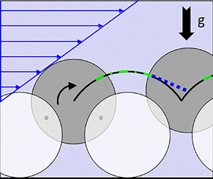



1. Introduction
Flow-induced particle motion is a fundamental feature of a wide variety of industrial and natural processes. The particles usually reside on a patterned or rough surface or on a granular bed. This includes, for instance, the cleaning of surfaces (Burdick, Berman & Beaudoin Reference Burdick, Berman and Beaudoin2005; Kondo & Ando Reference Kondo and Ando2019), filtration and fractionation (Meland & Norrman Reference Meland and Norrman1966; Charru et al. Reference Charru, Larrieu, Dupont and Zenit2007), pneumatic conveying (Stevanovic et al. Reference Stevanovic, Stanojevic, Jovovic, Radic, Petrovic and Karlicic2014) or sediment transport in rivers, on coastal lines and in dune formation (Groh et al. Reference Groh, Wierschem, Rehberg, Aksel and Kruelle2008; Wierschem et al. Reference Wierschem, Groh, Rehberg, Aksel and Kruelle2008; Carneiro, Pähtz & Herrmann Reference Carneiro, Pähtz and Herrmann2011; Seizilles et al. Reference Seizilles, Devauchelle, Lajeunesse and Metivier2013). It is also of particular importance for the positioning and assembling of particles for construction of metamaterials (Yin et al. Reference Yin, Lu, Gates and Xia2001; Bleil, Marr & Bechinger Reference Bleil, Marr and Bechinger2006; Nguyen & Yoon Reference Nguyen and Yoon2009) and laminar flow assays (Brooks & Tozeren Reference Brooks and Tozeren1996). Consequently, the flow-induced onset of particle motion has been studied intensively over the past decades; see, for instance, the articles by Loiseleux et al. (Reference Loiseleux, Gondret, Rabaud and Doppler2005), Ouriemi et al. (Reference Ouriemi, Aussillous, Medale, Peysoon and Guazzelli2007), Hong, Tao & Kudrolli (Reference Hong, Tao and Kudrolli2015), Métivier, Lajeunesse & Devauchelle (Reference Métivier, Lajeunesse and Devauchelle2017), Dey & Ali (Reference Dey and Ali2018), Topic et al. (Reference Topic, Hou, Illigmann, Luzi, Agudo and Wierschem2019a,Reference Topic, Retzepoglu, Wensing, Illigmann, Luzi, Agudo and Wierschemb), Shih & Diplas (Reference Shih and Diplas2019), Pähtz et al. (Reference Pähtz, Clark, Valyrakis and Durán2020, Reference Pähtz, Liu, Xia, Hu, He and Tholen2021), and references cited therein. Beyond the threshold for particle motion, the particles may roll, slide or lift off (Valyrakis et al. Reference Valyrakis, Diplas, Dancey, Greer and Celik2010; Agudo, Dasilva & Wierschem Reference Agudo, Dasilva and Wierschem2014; Agudo et al. Reference Agudo, Illigmann, Luzi, Laukart, Delgado and Wierschem2017a,Reference Agudo, Luzi, Han, Hwang, Lee and Wierschemb).
For the motion above the threshold, most studies have focused on the mass flow rate in granular beds. For an overview of models for the flow rate in turbulent and laminar flows, see e.g. Ouriemi, Aussillous & Guazzelli (Reference Ouriemi, Aussillous and Guazzelli2009). An important step in understanding the mechanisms governing the particle flow rate is considering the motion of single beads along substrates made from other particles (Charru, Mouilleron & Eiff Reference Charru, Mouilleron and Eiff2004). Yet only a few studies focus on the motion of single particles on granular beds. Meland & Norrman (Reference Meland and Norrman1966) studied the motion of individual beads of different size on regular granular beds exposed to turbulent flow. Near the threshold, they observed discontinuous motion. It became continuous at higher forcing, where the beads did not descend completely into the substrate pockets at higher velocities. Abbott & Francis (Reference Abbott and Francis1977) studied the motion of single grains over a granular bed in a turbulent flow at Shields numbers up to about ten times the critical Shields number. Apart from particle motion along the substrate, they observed saltation and suspension. Yet, already at Shields numbers  $20\,\%$ larger than the critical one, the particle moved mainly in flights. They found a close-to-linear relation between the mean particle velocity in the flow direction and the shear velocity. Although the particle velocity was higher during flights than along the bed, the close-to-linear relation was found to be valid as the grain changed gradually from predominantly moving along the bed to predominantly flying over it.
The motion of a single bead along a substrate exposed to laminar shear flow was studied by Charru et al. (Reference Charru, Larrieu, Dupont and Zenit2007). They considered the bead motion on an irregularly arranged bed made of spheres of the same size in an annular channel. At the onset of continuous motion, they measured average bead velocities of about  $10\,\%$ of the Stokes settling velocity. They found that the average streamwise velocity increases linearly with the Shields number as long as it is smaller than the settling velocity. At higher Shields numbers, it increases more strongly. To describe their findings, they developed a model with effective parameters. Based on ideas of Bagnold (Reference Bagnold1973), they assumed for their average properties a dynamic equilibrium between flow-induced forces and an effective friction force representing momentum transfer to the bed. The effective parameters were obtained from fits to the data and using the results of Goldman, Cox & Brenner (Reference Goldman, Cox and Brenner1967b) for the motion of a bead near a flat plane in the creeping-flow limit.
Like Charru et al. (Reference Charru, Larrieu, Dupont and Zenit2007), we study the motion of a single bead along a substrate made of particles of the same size. Different from them, we consider the motion over regularly arranged substrates. Apart from being important, for instance, in positioning e.g. in microfluidic systems, it allows highlighting and quantifying the impact of the substrate geometry on the particle motion. We focus on the motion at Shields numbers of same order as the critical one, where the particle moves along the substrate, and on particle Reynolds numbers, where inertia can be neglected. Similar to previous studies on the onset of motion (Agudo & Wierschem Reference Agudo and Wierschem2012), we carry out experiments on triangular and quadratic arrangements, and vary the spacing between the substrate particles. The role of substrate spacing has also been considered in studies on dry granular particle motion down inclined planes in two dimensions. Apart from regular arrangements (Dippel, Batrouni & Wolf Reference Dippel, Batrouni and Wolf1996), it has been varied often randomly to model roughness (Riguidel et al. Reference Riguidel, Jullien, Ristow, Hansen and Bideau1994; Ristow, Riguidel & Bideau Reference Ristow, Riguidel and Bideau1994; Batrouni, Dippel & Samson Reference Batrouni, Dippel and Samson1996; Shojaaee et al. Reference Shojaaee, Brendel, Török and Wolf2012).
While there are numerous approaches to describe and model the particle mass flow rate in bed-load transport (Ouriemi et al. Reference Ouriemi, Aussillous and Guazzelli2009), to the best of our knowledge, the motion of a single particle along a substrate in laminar flow conditions has been described only by Charru et al. (Reference Charru, Larrieu, Dupont and Zenit2007), who determine effective quantities describing the motion along the randomly arranged substrate in their experiments. To focus on the impact of the substrate geometry, we extend our model for the onset of motion (Agudo et al. Reference Agudo, Illigmann, Luzi, Laukart, Delgado and Wierschem2017a; Topic et al. Reference Topic, Retzepoglu, Wensing, Illigmann, Luzi, Agudo and Wierschem2019b) to conditions above the threshold. It allows considering rolling and sliding along the substrates as well as detachment. Depending on the substrate geometry and on the Shields number, the model shows that all three types of motion may occur along the substrate, and reveals the impact of the different types of motion on the average velocity.
The article is arranged as follows. The experimental set-up is described in § 2, and the experimental results in § 3. To describe these findings, we derive a model in § 4. The results are discussed in § 5, and the main conclusions are summarized in § 6.
2. Experimental set-up
A single bead is deposited on regular substrates and exposed to a laminar shear flow. The regular substrates consist of a monolayer of uniformly sized soda-lime glass spheres of  $(405.9 \pm 8.7)\,\mathrm {\mu }$m diameter as in former studies (Agudo et al. Reference Agudo, Dasilva and Wierschem2014; Topic et al. Reference Topic, Retzepoglu, Wensing, Illigmann, Luzi, Agudo and Wierschem2019b). The mobile beads have the same size. The substrate spheres are fixed and arranged in quadratic configurations with different spacing between the particles. Like Agudo & Wierschem (Reference Agudo and Wierschem2012), we use substrates with spacings $a=14$, 94 and $109\,\mathrm {\mu }$m between the spheres, which correspond to a ratio between spacing and bead diameter $D_P$ of about 0.035, 0.232 and 0.269, respectively. Also, we carry out experiments on a substrate in a triangular arrangement with spheres in direct contact. In this case, the substrate grooves are oriented with respect to the main flow direction at angle ${\rm \pi} /6$. Figure 1 shows a view on different substrate geometries.

Figure 1. Substrate geometries. Top view on the triangular configuration (a), and on the quadratic configuration with spacings (b)  $14\,\mathrm {\mu }$m and (c) $109\,\mathrm {\mu }$m. Main flow direction is from left to right as indicated by the large blue arrows in the sketches. On the triangular arrangement, the bead travels in a zigzag manner along the grooves as indicated by the thick black arrows.
The substrates, with dimensions  $70\times 15\,{\rm mm}^2$, are glued to glass microscope slides measuring $70\times 25\,{\rm mm}^2$ and placed off-centre on the bottom of a transparent circular container with inner diameter 176 mm and 25 mm high sidewalls made from Plexiglas. Figure 2 shows a sketch of the container with the rheometer disk. This container is placed into an MCR 301 rotational rheometer from Anton Paar. A laminar shear flow is induced with a parallel-disk configuration. The rotating top plate is made from Plexiglas and has diameter 150 mm. At the bead, which is positioned at distance $r$ from the turning axis, the shear rate $\dot \gamma$ is
 \begin{equation} \dot\gamma=\frac{\varOmega r}{h}, \end{equation}
where  $\varOmega$ is the angular velocity, and $h$ is the gap width, defined as the distance from the top of the substrate spheres to the rotating plate. Both angular velocity and gap width are controlled with the rheometer. All experiments are performed at gap width 2 mm.

Figure 2. Sketch of the container and the rotating rheometer disk.
The Reynolds number  ${{Re}}$ and particle Reynolds number ${{Re}}_P$ are defined as
 \begin{equation} {{Re}}=\frac{\rho_F \dot\gamma h^2}{\mu},\quad {{Re}}_P={{Re}}\left(\frac{D_P}{h}\right)^2, \end{equation}
where  $\mu$ is the dynamic viscosity, and $\rho _F$ is the liquid density. The impact of the flow on the bead is characterized by the Shields number (Agudo & Wierschem Reference Agudo and Wierschem2012; Agudo et al. Reference Agudo, Dasilva and Wierschem2014; Topic et al. Reference Topic, Retzepoglu, Wensing, Illigmann, Luzi, Agudo and Wierschem2019b), i.e. the ratio between the characteristic shear force acting on the particle and its resistant effective particle weight:
 \begin{equation} \theta=\frac{\mu \dot\gamma}{\left(\rho_P-\rho_F\right)g D_P}, \end{equation}
where  $\rho _P$ is the particle density, and $g$ is the acceleration due to gravity.
To study the impact of inertia, we vary the Reynolds number and the particle density by using different liquids and bead materials. Yet the particle Reynolds number remains lower than 2 in our experiments. Table 1 summarizes the properties of the employed beads and fluids. Table 2 depicts the critical Shields number,  $\theta _C$, for the onset of particle motion of each of the substrates determined previously (Agudo & Wierschem Reference Agudo and Wierschem2012). The temperature is fixed at $(295.15 \pm 0.5)\,{\rm K}$. This is controlled with a P-PTD 200 Peltier element connected to the rheometer and measured with an external thermometer.
Table 1. Bead and fluid properties.

Table 2. Critical Shields numbers for the onset of motion (Agudo & Wierschem Reference Agudo and Wierschem2012).

The experiments are carried out by applying a sudden shear-rate jump on the mobile bead with a step width of the rheometer of about 0.02 s, starting from conditions below the critical Shields number to a state above threshold that is kept constant while the beads move along the substrate. Solving the transient plane Couette flow for flat plates with gap width 2 mm, we arrive at characteristic times of about 0.2 s or less for reaching  $99\,\%$ of the steady value near the bottom (0.2 mm distance) with our oils. Particle motion is recorded from the top through the transparent rotating disk with a digital camera with a chip of $752\times 480$ pixels and a frame rate up to 120 Hz coupled to a macro-objective that incorporates a tilted mirror. The bead moving along the substrate is tracked with an image-processing routine (Agudo et al. Reference Agudo, Dasilva and Wierschem2014, Reference Agudo, Luzi, Han, Hwang, Lee and Wierschem2017b, Reference Agudo, Han, Park, Kwon, Loekman, Luzi, Linderberger, Delgado and Wierschem2018).
3. Experimental results
To check the ability of the set-up for analysing the impact of the substrate geometry on the mean particle velocity, we first identify a parameter range that is independent of any boundary conditions. This includes the inherent rotating motion of the rheometer disk. The critical Shields number for the onset of particle motion is hardly affected by the angle between flow direction and the symmetry axis of the substrate around its minimum values within the interval of about  ${\rm \pi} /6$ (Agudo & Wierschem Reference Agudo and Wierschem2012). Accordingly, the mobile bead may follow a straight path of about 17 mm with a reduction of the maximum shear stress by about $3\,\%$. A distance of 17 mm corresponds to about 30 positions for the substrate with widest spacing between the spheres. Moreover, for small particle Reynolds numbers as considered in our experiments, centrifugal forces caused by the rotating disk motion are negligible (Agudo & Wierschem Reference Agudo and Wierschem2012; Agudo et al. Reference Agudo, Dasilva and Wierschem2014). In our study, the bead moves along the substrate grooves as reported previously for the onset of motion (Agudo & Wierschem Reference Agudo and Wierschem2012). This holds also for triangular arrangements of substrate spheres.
Figure 3(a) depicts the trajectory of a single glass bead at Shields number 0.058 on the substrate with narrowest spacing. For this geometry, the Shields number is about  $1.5 \times \theta _C$. The experiment is performed by placing the mobile bead at radius 50 mm from the centre of the disk, and using the less viscous oil. The bead travels over 38 substrate pockets, which corresponds to around 16 mm, showing a straight trajectory during the entire path. The lateral displacement is marginal and due mainly to small defects on the regular substrate. Figure 3(b) shows the streamwise position of the bead as a function of time. The bead achieves a constant mean equilibrium velocity in the early stage of its motion right after the shear-rate jump, being barely affected by the inherent rotating motion of the rheometer disk within the considered pathway.

Figure 3. (a) Path line of a glass bead during its displacement along 38 substrate pockets. Flow from left to right. Experiment performed with the less viscous oil. (b) Particle position as a function of time. The dashed line is a linear fit to the data, drawn to guide the eye, and  $a/D_P=0.035$, $\theta =0.058$.
In order to take a close-up tracking of the bead motion, the zoom on the macro-objective is increased to record the particle displacement along seven substrate pockets. Figure 4(a) shows the path of a glass bead at  $\theta = 2.5 \times \theta _C$. The less viscous oil is used to perform the experiments yielding a particle Reynolds number of about 1. The particle is placed at radius 50 mm from the centre of the disk. The initial position on the substrate is given by orientation angle zero with respect to the symmetry axis of the substrate (position A in the inset). The overall distance is measured with a 1 mm stage micrometer. It corresponds to a pathway of $2.99 \pm 0.05$ mm. We remark that this distance is well below the range beyond which the deviation between the path of the bead along the substrate grooves and the main flow direction becomes noticeable, i.e. beyond about 17 mm. Accordingly, the bead follows a straight line.

Figure 4. (a) Path line of a glass bead during its displacement along seven substrate pockets, and (b) particle position as a function of time. Black, red and blue curves represent experiments with the particle placed at the initial positions A, B and C, as indicated in the inset, respectively. The experiments are performed with the less viscous oil at radius 50 mm and at constant Shields number 0.1, corresponding to  $\theta / \theta _C = 2.5$. Here, $a/D_P=0.035$.
Figure 4(b) shows the streamwise position of the bead as a function of time for the substrate with narrowest spacing. It compares the evolution of the particle position in the same region for the different initial positions indicated in the inset. The experiments are repeated twice. All results are in good agreement, independent of the initial position within a standard deviation of about  $1.6\,\%$. Hence the experimental results confirm that the bead reaches its equilibrium velocity in the early stage of the motion, in line with previous observations (Agudo & Wierschem Reference Agudo and Wierschem2012). The transient plane Couette flow, where $99\,\%$ of the steady velocity profile is reached in about 0.2 s in this case, appears not to be relevant. The periodic velocity fluctuations are due to local variations in the substrate geometry. Averaging over the substrate periodicity, the bead position changes linearly in time. At the low particle Reynolds numbers considered, and consistent with former results (Agudo & Wierschem Reference Agudo and Wierschem2012), the bead does not exhibit any acceleration phase beyond neighbouring substrate positions. In what follows, we always study a travel distance of seven substrate pockets to determine a representative value for the mean particle velocity.
Figures 5(a,b) show the bead position as a function of time for different pathways at  $\theta /\theta _C = 1.3$ and $2.5$, respectively. The inset indicates the three neighbouring pathways on the substrate in which the distance from the turning axis of the rheometer changes by $\pm$1 %. First, the critical Shields number is measured for all substrate pockets of the different pathways, showing values that agree within the range of uncertainty with those presented in table 2 (Agudo & Wierschem Reference Agudo and Wierschem2012). Above the threshold, the bead travels along the substrate with a velocity that is modulated due to the substrate topology as in figure 4(b). The modulation amplitude diminishes as the Shields number increases, as is apparent from comparing figures 5(a) and 5(b). At $\theta /\theta _C = 2.5$, all particle trajectories coincide within the standard deviation $2\,\%$. At Shields numbers near the threshold as in figure 5(a), where the bead moves rather slowly and the modulation is pronounced, the bead motion is very susceptible to local substrate variations, resulting in larger deviations in the local velocity. For $\theta /\theta _C=1.3$, the experiments were repeated twice. Notwithstanding the local variations, the average particle velocity varies by only about $3.5\,\%$.

Figure 5. Particle position during its motion along seven substrate pockets on the substrate with narrowest spacing at Shields numbers (a) 0.052 and (b) 0.1, corresponding to  $\theta / \theta _C = 1.3$ and 2.5, respectively. Black, red and blue curves correspond to experimental runs with the bead placed on paths 1, 2 and 3 indicated in the inset, respectively. The experiments are performed using the less viscous oil at radius about 50 mm.
Finally we consider the influence of the substrate on the average streamwise bead velocity. To minimize the impact of curvature of the azimuthal flow in the rheometer, we study the average velocity along a symmetric tangential path of seven substrate particles. Figure 6 shows the average bead velocity in the main flow direction,  $\langle U \rangle$, as a function of the Shields number for the different substrates. The velocity is scaled with the Stokes settling velocity, $U_S$, which depends on both the submerged weight of the bead and on the viscosity. It is defined as (Charru et al. Reference Charru, Larrieu, Dupont and Zenit2007)
 \begin{equation} U_S=\frac{(\rho_P-\rho_F)gD_P^2}{18\mu}. \end{equation}
The figure covers the range of Shields numbers from near critical up to about  $5 \theta _C$. The particle Reynolds number ranges from $5 \times 10^{-3}$ up to about $2$. Even at the studied particle Reynolds numbers above $1$, inertia and centrifugal forces have only a minor impact, as shown by Agudo & Wierschem (Reference Agudo and Wierschem2012). The experiments were usually repeated three times. The error bars in the diagram indicate the range of uncertainty of the measurements.

Figure 6. Average bead velocity in the mean flow direction. Triangles, squares, diamonds and circles indicate substrates with triangular arrangement and with quadratic arrangements with spacing  $a/D_P=0.035$, 0.232 and 0.269, respectively. Blue, red and grey symbols depict measurements with beads made from glass, PMMA and steel, respectively. Open and closed symbols correspond to lower and higher viscosities, respectively. The lines are exemplary linear fits to data of different arrangements.
For each material and substrate combination, the data can be fitted by a linear relationship between the dimensionless average streamwise bead velocity and the Shields number (regression coefficient  $R^2>0.99$ for all cases). For each substrate, the data for different viscosities and bead materials group within narrow corridors. As a tendency, it appears that the dimensionless velocities of the steel beads seem to be slightly smaller than the others. This may be due to the somewhat smaller diameter; see table 1. Comparing the data of the different oils, it appears that the beads seem to travel slightly faster at lower viscosity.
The dimensionless average velocity is related to the critical Shields number that corresponds to the different substrates; see table 2. The critical Shields number quantifies the resistance for the onset of motion, and increases with the maximum stability angle and the shielding from the flow (Agudo & Wierschem Reference Agudo and Wierschem2012; Agudo et al. Reference Agudo, Illigmann, Luzi, Laukart, Delgado and Wierschem2017a; Topic et al. Reference Topic, Retzepoglu, Wensing, Illigmann, Luzi, Agudo and Wierschem2019b). Accordingly, as the bead travels along the substrate, it has to overcome larger local slopes and is less exposed to the flow on substrates with higher critical Shields numbers. This is in line with the observation that the increase of the average velocity is slightly weaker for higher critical Shields numbers. Note that the intercept of the fits is slightly below the critical Shields number.
Assuming a linear dependence on the critical Shields number, the observations on the dependence of the dimensionless average velocity on the Shields number and on the critical Shields number can be described as
 \begin{equation} \frac{\langle U \rangle}{U_S}=A_1 [( 1- A_2 \theta_C) \theta - A_3 \theta_C], \end{equation}
where  $A_i$ are fit parameters. Figure 7 shows the resulting master curve for the data set. Here, the parameters $A_i$ have been determined without taking into account the data on the steel beads or the triangular substrate. They result in
 \begin{equation} A_1=4.9 \pm 0.1, \quad A_2=4.6 \pm 0.3,\quad A_3=0.67 \pm 0.02. \end{equation}
Although disregarded for the fit, the data on steel beads and in particular on the triangular substrate obey quite well the master curve in figure 7.

Figure 7. Master curve for the average bead velocity in the mean flow direction. Fit parameters obtained without the data on steel beads and triangular substrate. The symbol assignment is identical to that in figure 6. To guide the eye, the line indicates slope 1.
4. Model
To analyse the particle motion along the substrate, we set up a model for the shear-induced motion in the creeping-flow limit. In the model, a rigid bead is considered to be exposed to a linear shear flow. The contact to the substrate is adhesionless. In the creeping-flow limit, the lift force vanishes and the drag can be decomposed into a shear and translational and rotational contributions. The shear contribution has been modelled previously for the onset of flow-induced particle motion (Agudo et al. Reference Agudo, Illigmann, Luzi, Laukart, Delgado and Wierschem2017a; Topic et al. Reference Topic, Hou, Illigmann, Luzi, Agudo and Wierschem2019a,Reference Topic, Retzepoglu, Wensing, Illigmann, Luzi, Agudo and Wierschemb). Likewise, we disregard deviations in the flow field caused by the presence of the substrate spheres, and model the partial shielding of the bead from the flow by the substrate spheres by an effective zero level; see figure 8(a). The effect of the neighbouring substrate spheres on the translational and rotational bead motion is modelled again by flat walls.

Figure 8. Projection of the geometry near the mobile bead onto the  $xz$ plane. The $y$ axis points into the plane. (a) Geometrical and kinematic quantities describing the system. The horizontal dashed line indicates the effective zero level of the shear flow. The two circles above the zero level are the bead in its initial position in the substrate pocket (full circle) and next substrate pocket (dotted circle). The dash-dot line indicates the trajectory of the bead centre moving at velocity $U_P$; $\chi$ is the angle between the bead surface at effective zero level and its vertical axis. (b) Forces acting on the bead. The lever arm of the shear force, $L_S$, is shown together with the instantaneous inclination angle, $\phi _T-\phi$.
We focus on the quadratic arrangement with different spacings, where the grooves are in line with the main flow direction. Initially, the bead rests in a substrate pocket, where it is in contact with the four substrate spheres that confine the pocket. The contact points are on the line between the bead and sphere centres.
As in experiments (Agudo & Wierschem Reference Agudo and Wierschem2012), we consider the motion of the bead through the substrate grooves. At onset, the bead rolls over the substrate without slip (Agudo et al. Reference Agudo, Dasilva and Wierschem2014). Kudrolli, Scheff & Allen (Reference Kudrolli, Scheff and Allen2016) have shown experimentally and theoretically that rolling stands as the mechanism of motion for well-exposed individual beads even at high particle Reynolds numbers. Hence we will start our considerations with this case. Nevertheless, as the bead rolls along the substrate, the Coulomb friction limit may be exceeded and the bead may slide. While it rolls or slides, the bead remains in contact with the substrate spheres that form the grooves at two contact points. Finally, if the normal force between the moving bead and the substrate becomes zero, then the bead may detach from the substrate. In what follows, we will consider each of these three cases in the creeping-flow limit.
At onset, the bead needs to overcome the maximum stability angle in the pocket of the substrate,  $\phi _T$. As it moves along the substrate to the next pocket, the deviation from this angle, $\phi$, increases continuously. The momentary angle, $\phi _T-\phi$, first decreases continuously to zero at the crest and then becomes negative until the bead reaches the neighbouring pocket; see figure 8(a).
While the effective weight  $F'_G$, i.e. gravity minus buoyancy, keeps the bead in the substrate pocket, the flow-induced force $F_M$ can destabilize the position in the substrate pocket beyond the critical Shields number, and moves the bead forward. The mobile bead interacts with the substrate via the contact forces in normal and tangential directions $F_N$ and $F_F$, respectively. Both $F_N$ and $F_F$ are the resultants of the forces at the contact points with the substrate. We remark that the out-of-plane component of the normal force contributes to the solid friction and is absorbed by the respectively friction coefficients. Balancing the forces in the radial and tangential directions indicated in figure 8(b) by the vectors $\boldsymbol {r}$ and $\boldsymbol {t}$, and the torque around the bead centre, the equations of motion for the bead read
 \begin{gather} (m_P+m_a)a_r=F_N+F_{Mr}-F'_G\cos(\phi_T-\phi), \end{gather}
 \begin{gather}(m_P+m_a)a_t=F_F+F_{Mt}-F'_G\sin(\phi_T-\phi), \end{gather}
 \begin{gather}I\,\frac{\mathrm{d}\omega}{\mathrm{d}t}=T_M-F_F\,\frac{D_T}{2}, \end{gather}
with the accelerations  $a_r$ and $a_t$, and the flow-induced force contributions $F_{Mr}$ and $F_{Mt}$, in the radial and tangential directions, respectively. The mass of the bead is indicated by $m_P=({\rm \pi} /6)\rho _PD_P^3$. With the fluid density $\rho _F$, the added mass due to fluid acceleration can be expressed by $m_a=c_a m_P \rho _F/\rho _P$. For a bead moving in a liquid far away from solid surfaces, $c_a=1/2$. The moment of inertia of the bead, the angular bead velocity and the flow-induced torques are $I=({\rm \pi} /60)\rho _PD_P^5$, $\omega$ and $T_M$, respectively. The lever arm of the solid-friction force $F_F$ is half the distance between the centres of mobile and substrate beads projected into the $xz$ plane, $D_T$; see figure 8(a). This turning radius can be expressed with the maximum stability angle:
 \begin{equation} \phi_T=\arctan\left(\frac{D_P+a}{\sqrt{4D_P^2-2(D_P+a)^2}}\right),\quad D_T=\sqrt{D_P^2-\left(\frac{D_P+a}{2}\right)^2}. \end{equation}
The accelerations and the angular velocity can be expressed as
 \begin{equation} a_t=D_T\,\frac{\mathrm{d}^2\phi}{\mathrm{d}t^2},\quad a_r=D_T \left(\frac{\mathrm{d}\phi}{\mathrm{d}t}\right)^2,\quad \omega=\frac{\mathrm{d}\beta}{\mathrm{d}t}, \end{equation}
where  $\beta$ is the rotation angle of the bead. To express the equations of motion (4.1) in dimensionless form, we use the shear rate $\dot \gamma$ as the inverse of the characteristic time scale. Hence
 \begin{equation} t=\frac{1}{\dot\gamma}\,\hat{t}. \end{equation}
Here, as in what follows, the hat identifies a dimensionless quantity. As characteristic scale for the normal force, we take the effective gravity  $F'_G=({{\rm \pi} }/{6})(\rho _P-\rho _F)D_P^3 g$. For the solid-friction force $F_F$ and the flow-induced force and torque, we employ the viscous scaling:
 \begin{equation} \left.\begin{gathered} F_M=\frac{3}{2}{\rm \pi}\mu\dot\gamma D_P^2 \hat{F}_M,\quad T_M=\frac{3}{2}{\rm \pi}\mu\dot\gamma D_P^3 \hat{T}_M,\quad F_F=\frac{3}{2}{\rm \pi}\mu\dot\gamma D_P^2 \hat{F}_F,\\ F_N=\frac{\rm \pi}{6}(\rho_P-\rho_F)D_P^3 g \hat{F}_N. \end{gathered}\right\} \end{equation}
With these scalings, the equations of motion (4.1) take the form
 \begin{gather} {{Re}}_P\,\frac{\rho_P}{\rho_F}\,\frac{D_T}{D_P} \left(1+ c_a\, \frac{\rho_F}{\rho_P}\right) \left(\frac{\mathrm{d}\phi}{\mathrm{d}\hat{t}}\right)^2 = \frac{1}{\theta}\,\hat{F}_N+9 \hat{F}_{Mr}-\frac{1}{\theta}\,\cos(\phi_T-\phi), \end{gather}
 \begin{gather}{{Re}}_P\,\frac{\rho_P}{\rho_F}\,\frac{D_T}{D_P} \left(1+ c_a\,\frac{\rho_F}{\rho_P}\right) \frac{\mathrm{d}^2\phi}{\mathrm{d}\hat{t}^2}=9\hat{F}_F+9\hat{F}_{Mt}-\frac{1}{\theta}\,\sin(\phi_T-\phi), \end{gather}
 \begin{gather}{{Re}}_P\,\frac{\rho_P}{\rho_F}\, \frac{\mathrm{d}^2\beta}{\mathrm{d}\hat{t}^2}=90\hat{T}_M-45\,\frac{D_T}{D_P}\, \hat{F}_F, \end{gather}
where we have introduced the particle Reynolds number and the Shields number defined in (2.2a,b) and (2.3), respectively.
As we are interested in the creeping-flow limit, we may set the left-hand sides of (4.6) to zero. For small but finite  ${{Re}}_P$, we may neglect the inertia terms if the Stokes number ${{Re}}_P (\rho _P/\rho _F) \ll 1$, as $D_T/D_P$ is about $1$. It ranges between $\sqrt {2} /2$ and $\sqrt {3} /2$ for quadratic lattices, where the maximum spacing is $a/D_P=\sqrt {2}-1$.
The flow-induced force is divided into drag and lift forces. In the creeping-flow limit, the lift force vanishes due to symmetry (Goldman et al. Reference Goldman, Cox and Brenner1967b; Leighton & Acrivos Reference Leighton and Acrivos1985; Hornung Reference Hornung2006). At near creeping-flow conditions, the lift force is proportional to the particle Reynolds numbers and may account for about 7 % of the drag force at  ${\it Re}_P=1$ (Leighton & Acrivos Reference Leighton and Acrivos1985). In the creeping-flow limit, the drag force can be decomposed into three contributions: a force due to the shear flow acting on a fixed bead, $\hat {F}_S$, and forces due to bead translation, $\hat {F}_T$, and rotation, $\hat {F}_R$, in a quiescent fluid (Goldman et al. Reference Goldman, Cox and Brenner1967b). In the current model, the force vectors are parallel to the vectors drawn in figure 8(b). The Basset history force is neglected; its validity is discussed in Appendix A. For the flow-induced torque, the decomposition is similar.
The shear flow is imposed in the horizontal direction. As the modulation caused by the presence of the substrate spheres can be neglected in a first approximation (Agudo et al. Reference Agudo, Illigmann, Luzi, Laukart, Delgado and Wierschem2017a; Topic et al. Reference Topic, Hou, Illigmann, Luzi, Agudo and Wierschem2019a,Reference Topic, Retzepoglu, Wensing, Illigmann, Luzi, Agudo and Wierschemb), we consider  $\hat {F}_S$ acting in horizontal direction in the model. Since the force contributions $\hat {F}_T$ and $\hat {F}_R$ are due to the bead motion in a quiescent fluid, these forces act in the direction of the local bead motion, hence locally tangential to the substrate when the bead is in contact. With these replacements, the equations of motion (4.6) take the following form in the creeping-flow limit:
 \begin{gather} \hat{F}_N=9 \theta \hat{F}_S\sin(\phi_T-\phi)+\cos(\phi_T-\phi), \end{gather}
 \begin{gather}0=\hat{F}_F+\hat{F}_S\cos(\phi_T-\phi)+\hat{F}_T+\hat{F}_R-\frac{1}{9 \theta} \sin(\phi_T-\phi), \end{gather}
 \begin{gather}\hat{F}_F=2\,\frac{D_P}{D_T} \left(\hat{F}_S\,\frac{L_S}{D_P} +\hat{T}_T+\hat{T}_R \right), \end{gather}
where the torque induced by the shear flow on a bead at rest is calculated using the lever arm  $L_S$ with respect to the bead centre. The dependence of the lever arm on the geometrical properties is provided in Appendix B. For further details on the derivations of the terms, we refer to Agudo et al. (Reference Agudo, Illigmann, Luzi, Laukart, Delgado and Wierschem2017a). The normal force $\hat {F}_N$ can be determined from (4.7a). The solid-friction force $\hat {F}_F$ can be eliminated by inserting (4.7c) into (4.7b).
To solve the resulting equations, we need to specify now the drag force and torque contributions. According to Goldman et al. (Reference Goldman, Cox and Brenner1967b), the contributions due to bead translation and rotation in a quiescent fluid near a flat wall are
 \begin{equation} \left.\begin{gathered} \hat{F}_T=\hat{U}_PF_T^*=\frac{D_T}{D_P}\,\frac{\mathrm{d}\phi}{\mathrm{d}\hat{t}}\,F_T^*, \quad \hat{F}_R=\frac{\mathrm{d}\beta}{\mathrm{d}\hat{t}}\,F_R^*,\\ \hat{T}_T=\hat{U}_PT_T^*=\frac{D_T}{D_P}\,\frac{\mathrm{d}\phi}{\mathrm{d}\hat{t}}\,T_T^*, \quad \hat{T}_R=\frac{\mathrm{d}\beta}{\mathrm{d}\hat{t}}\,T_R^*, \end{gathered}\right\} \end{equation}
with the bead velocity  $U_P=D_T \,\mathrm {d}\phi / \mathrm {d}t$. The factors with asterisks depend only on the geometrical properties. We approximate the impact of the substrate on the bead translation and rotation by flat walls in contact with the bead; see figure 9. The flow field during the bead motion is influenced mainly by the presence of the directly neighbouring substrate spheres; i.e. as the bead moves along a groove between two spheres, its motion is also affected by the presence of the next neighbouring pair of spheres. While the contribution of the neighbouring spheres vanishes at $\phi = \phi _T$, it is as large as the one of the substrate spheres if the bead is in the substrate pocket at $\phi _T = {\rm \pi}/ 2$; see figures 9(a) and 9(b). Accordingly, we model the impact of the neighbouring spheres at smaller $\phi _T$ by inclined walls (see figures 9c,d), hence with a contribution proportional to the inclination angle, i.e. ${\phi _T}/({{\rm \pi} /2})$. The same holds for the local angle $\phi _T-\phi$ during the motion of the bead along the substrate. To take into account the major effect of the neighbouring sphere, we may symmetrize the impact disregarding minor variations in the angle. This results in the weighing factor for the local wall effects on the translational and rotational contributions:
 \begin{equation} 1+\frac{\left| \phi_T-\phi \right|}{{\rm \pi} /2}. \end{equation}
Hence, with this weighing term and using Goldman's results for a bead at a plane (Goldman et al. Reference Goldman, Cox and Brenner1967b), we arrive at the coefficients in the current scaling:
 \begin{equation} \left.\begin{gathered} F_T^*={-}\frac{32}{7}\left( 1+\frac{\left| \phi_T-\phi \right|}{{\rm \pi} /2} \right), \quad F_R^*=\frac{1}{8}\left( 1+\frac{\left| \phi_T-\phi \right|}{{\rm \pi} /2} \right), \\ T_T^*=\frac{1}{8}\left( 1+\frac{\left| \phi_T-\phi \right|}{{\rm \pi} /2} \right),\quad T_R^*={-}\frac{7}{8}\left( 1+\frac{\left| \phi_T-\phi \right|}{{\rm \pi} /2} \right). \end{gathered}\right\} \end{equation}
Here, we disregard the logarithmic divergence in their expressions that are due to the motion in a thin lubrication film between particle and wall. This is because no significant impact of a lubrication film has been observed in experiment for a bead moving along a flat plane. Its lack has been attributed to e.g. surface roughness (Smart, Beimfohr & Leighton Reference Smart, Beimfohr and Leighton1993), small air bubbles (Yang et al. Reference Yang, Seddon, Mullin, del Pino and Ashmore2006) and cavitation (Goldman, Cox & Brenner Reference Goldman, Cox and Brenner1967a; Ashmore, del Pino & Mullin Reference Ashmore, del Pino and Mullin2005).

Figure 9. Modelling the impact of neighbouring substrate spheres on the force and torque contributions due to bead translation and rotation in a quiescent fluid. (a) Mobile bead deeply buried into the substrate. (b) Modelling the impact of the neighbouring substrate spheres on the bead motion of case (a). (c) Mobile bead travelling along the substrate. (d) Modelling the impact of the neighbouring substrate spheres on the travelling bead of case (c).
For  $\hat {F}_S$ and its lever arm, we apply the model by Agudo et al. (Reference Agudo, Illigmann, Luzi, Laukart, Delgado and Wierschem2017a) replacing the maximum stability angle $\phi _T$ by the momentary inclination angle $\phi _T-\phi$. Agudo et al. (Reference Agudo, Illigmann, Luzi, Laukart, Delgado and Wierschem2017a) adapted the analytical solution by Goldman et al. (Reference Goldman, Cox and Brenner1967b) for the shear force on a spherical particle near a plane. In the present scaling, it reads
 \begin{equation} \hat{F}_S=fb(\phi), \end{equation}
where  $f$ is approximately 1.7 due to the presence of a flat wall. The factor $b(\phi )$ takes into account the shielding of the bead from the flow. Its relation to the geometrical properties is provided in Appendix B. See Agudo et al. (Reference Agudo, Illigmann, Luzi, Laukart, Delgado and Wierschem2017a) for further details on the derivation of the terms.
Inserting the forces and torques (4.8) and (4.11) into (4.7) yields
 \begin{gather} \hat{F}_N=9 fb\theta \sin(\phi_T-\phi)+\cos(\phi_T-\phi), \end{gather}
 \begin{gather}F_T^*\,\frac{D_T}{D_P}\,\frac{\mathrm{d}\phi}{\mathrm{d}\hat{t}}+F_R^*\, \frac{\mathrm{d}\beta}{\mathrm{d}\hat{t}}={-}\hat{F}_F-fb\cos(\phi_T-\phi)+ \frac{1}{9 \theta} \sin(\phi_T-\phi), \end{gather}
 \begin{gather}2T_T^*\,\frac{\mathrm{d}\phi}{\mathrm{d}\hat{t}}+2 T_R^*\,\frac{D_P}{D_T}\, \frac{\mathrm{d}\beta}{\mathrm{d}\hat{t}}={-}2 fb\, \frac{L_S}{D_T}+\hat{F}_F. \end{gather}
4.1. Rolling motion
For a bead rolling along the substrate, the following kinematic relation holds:
 \begin{equation} \dot\beta=2 \dot\phi. \end{equation}
Eliminating  $\hat {F}_F$ by inserting (4.12c) into (4.12b) results in
 \begin{equation} \frac{\mathrm{d}\phi}{\mathrm{d}\hat{t}} ={-}\frac{fb \left(2\,\dfrac{L_S}{D_T} + \cos(\phi_T-\phi) \right)-\dfrac{1}{9 \theta} \sin(\phi_T-\phi)}{F_T^*\, \dfrac{D_T}{D_P}+2F_R^*+2 T_T^*+ 4T_R^*\,\dfrac{D_P}{D_T}}. \end{equation}
Inserting the coefficients (4.10), we obtain from (4.14) that
 \begin{equation} \frac{\mathrm{d}\phi}{\mathrm{d}\hat{t}} = \frac{fb \left(2\,\dfrac{L_S}{D_T} + \cos(\phi_T-\phi) \right)-\dfrac{1}{9 \theta} \sin(\phi_T-\phi)}{\left( 1+\dfrac{\left| \phi_T-\phi \right|}{{\rm \pi} /2} \right) \left(\dfrac{32}{7}\,\dfrac{D_T}{D_P}+\dfrac{7}{2}\,\dfrac{D_P}{D_T}-\dfrac{1}{2} \right)}. \end{equation}
 We remark that the height of the bead centre over the contact points with the substrate is  $(D_T/2)\cos (\phi _T-\phi )$; see figure 8(a). Together with $L_S$, this height results into the lever arm of the shear force with respect to the contact points with the substrate, $L_{SC}$, and the equation can be rewritten in the form
 \begin{equation} \frac{\mathrm{d}\phi}{\mathrm{d}\hat{t}} = \frac{1}{9\,C(\phi)\,\theta} \left(18fb\,\frac{L_{SC}}{D_T}\,\theta - \sin(\phi_T-\phi) \right), \end{equation}
where  $C(\phi )$ abbreviates the denominator in (4.15), which is due to the contribution of translation and rotation of the bead in a quiescent fluid. Now, $\mathrm {d}\phi / \mathrm {d}\hat {t}$ may be expressed by the critical Shields number $\theta _C = D_T \sin \phi _T /(18fb(\phi _T)\,L_{SC}(\phi _T))$, which results from (4.16) for zero angular velocity at $\phi = 0$. We note that this results in the same critical Shields number as given by Agudo et al. (Reference Agudo, Illigmann, Luzi, Laukart, Delgado and Wierschem2017a). Then (4.16) takes the form
 \begin{equation} \frac{\mathrm{d}\phi}{\mathrm{d}\hat{t}} = \frac{\sin \phi_T}{9\,C(\phi)\,\theta} \left(\frac{b(\phi_T-\phi)}{b(\phi_T)}\,\frac{L_{SC}(\phi_T-\phi)}{L_{SC}(\phi_T)}\, \frac{\theta}{\theta_C} - \frac{\sin(\phi_T-\phi)}{\sin \phi_T} \right). \end{equation}
At Shields numbers several times the critical one,  $\mathrm {d}\phi /\mathrm {d}\hat {t}$ is around $1/5$, i.e. the bead velocity approaches up to about $20\,\%$ of the characteristic shear velocity. As the Shields number approaches the critical one, it decreases to zero at $\phi =\phi _T$.
We may use any of the forms (4.15)–(4.17) to determine the average bead velocity along the substrate in the streamwise direction  $\langle U \rangle$. In dimensional form, it reads
 \begin{equation} \langle U \rangle=\frac{2D_T\sin{\phi_T}}{\tau}, \end{equation}
where  $\tau$ is the time interval for travelling between neighbouring substrate pockets. With (4.17), it reads
 \begin{equation} \hat{\tau}=\frac{9\theta}{\sin \phi_T} \int_0^{2\phi_T} \frac{C(\phi)\,\mathrm{d}\phi}{\dfrac{b(\phi_T-\phi)}{b(\phi_T)}\, \dfrac{L_{SC}(\phi_T-\phi)}{L_{SC}(\phi_T)}\,\dfrac{\theta}{\theta_C}-\dfrac{\sin(\phi_T-\phi)}{\sin \phi_T}}. \end{equation}
Thus the average bead velocity for pure rolling motion scaled by the Stokes settling velocity  $U_S$ is given by
 \begin{equation} \frac{\langle U \rangle}{U_S} = 4\,\frac{D_T}{D_P}\, \frac{\sin^2{\phi_T}}{\displaystyle\int_0^{2\phi_T}\dfrac{C(\phi)\,\mathrm{d}\phi}{\dfrac{b(\phi_T-\phi)}{b(\phi_T)}\, \dfrac{L_{SC}(\phi_T-\phi)}{L_{SC}(\phi_T)}\,\dfrac{\theta}{\theta_C}-\dfrac{\sin(\phi_T-\phi)}{\sin \phi_T}}}, \end{equation}
where we used the scaling  $\hat {\tau }=\dot \gamma \tau$ and that $U_S=D_P \dot \gamma /(18 \theta )$. Since the bead is less exposed in the substrate valley, and the lever arm for the drag force is shortest there, each ratio of the first term in the denominator of the integral is larger than 1, while the second term, i.e. the ratio of the sine terms due to the effective weight, is always smaller than 1 if the bead is not in the substrate pocket. The exposure and lever arm are even functions of $\phi _T - \phi$, i.e. the denominator is the difference between an even and an odd function, reflecting the situation that the bead travels initially slowly uphill against gravity, and downhill in the later stage.
The integration in (4.20) is carried out numerically with the fourth-order Runge–Kutta method. Figure 10 shows the average velocity of purely rolling beads for substrate spacings ranging from the minimum to close to the maximum. With increasing substrate spacing, and thus with the maximum stability angle and the shielding from the flow, the average bead velocity declines monotonically. This holds also for its slope at higher Shields numbers. Close to the critical Shields number, the average velocities alter strongly. This is due to the changes of the low uphill velocities. This upsurge very close to the critical Shields numbers increases with substrate spacing.

Figure 10. Average velocity of purely rolling beads for different spacings  $a/D_P$ as a function of the Shields number according to (4.20). The respective values for $a/D_P$ are printed at the ends of the curves. The thick curve indicates the onset of detachment.
4.2. Sliding motion
The bead starts sliding if  $|F_F|>\eta _S F_N$, where $\eta _S$ is the static solid-friction coefficient (divided by $D_T/D_P$ due to the contribution of the normal force out-of-plane component to the solid friction). The development of the ratio of the two forces along the substrate is depicted exemplarily for different Shields numbers and substrate spacings in figure 11. Generally, $F_F / F_N$ is maximum in the pocket and decreases continuously during its motion along the substrate. Already on the uphill side, it becomes negative. At larger substrate spacings, it tends to infinity as the normal force becomes zero and the bead detaches from the substrate. In the pocket on the uphill side, $F_F / F_N$ also increases with spacing, as indicated by figure 11. As the Shields number increases, $F_F / F_N$ decreases. Hence at sufficiently small solid-friction coefficient, the bead starts sliding on the downhill side. At smaller $\eta _S$ or with increasing Shields number, the transition to sliding moves upstream. Furthermore, at low $\eta _S$, the bead slides in the pocket. Since the critical Shields number is larger for sliding than for rolling (Agudo et al. Reference Agudo, Illigmann, Luzi, Laukart, Delgado and Wierschem2017a), it may rotate in place at Shields numbers slightly above the threshold, as had been considered by Dey (Reference Dey1999) for turbulent flow conditions.

Figure 11. Ratio of tangential force to normal force along the substrate for two Shields number ratios  $\theta / \theta _C$, and three different substrate spacings. The vertical dashed lines indicate the positions where $F_N$ becomes zero.
In dimensionless form, the condition for the solid-friction force during sliding reads
 \begin{equation} |\hat{F}_F|=\eta_K\,\frac{1}{9\theta}\,\hat{F}_N, \end{equation}
where we applied the scaling (4.5a–d) and  $\eta _K$ is the kinematic solid-friction coefficient (along the lines of $\eta _S$ divided by $D_T/D_P$ due to the out-of-plane contribution). The kinematic relation (4.13) no longer holds, and $\phi$ and $\beta$ are now independent. Solving the set of (4.12) and (4.21) for $\mathrm {d}\phi /\mathrm {d}\hat {t}$ results in
 \begin{align} & \left(F_T^*-\frac{F_R^* T_T^*}{T_R^*} \right) \frac{D_T}{D_P}\, \frac{\mathrm{d}\phi}{\mathrm{d}\hat{t}} \nonumber\\ &\quad = fb\left( \frac{F_R^*}{T_R^*}\,\frac{L_S}{D_P} -\cos(\phi_T-\phi) -s\eta_K \left(\frac{1}{2}\,\frac{F_R^*}{T_R^*}\,\frac{D_T}{D_P} +1 \right) \sin(\phi_T-\phi)\right) \nonumber\\ &\qquad +\frac{1}{9 \theta} \left(\sin(\phi_T-\phi) -s\eta_K \left(\frac{1}{2}\,\frac{F_R^*}{T_R^*}\,\frac{D_T}{D_P} +1 \right) \cos(\phi_T-\phi)\right), \end{align}
and for  $\mathrm {d}\beta /\mathrm {d}\hat {t}$ gives
 \begin{align} & \left(F_R^*-\frac{F_T^* T_R^*}{T_T^*} \right) \frac{\mathrm{d}\beta}{\mathrm{d}\hat{t}} \nonumber\\ &\quad = fb\left( \frac{F_T^*}{T_T^*}\,\frac{L_S}{D_P} -\cos(\phi_T-\phi) -s\eta_K \left(\frac{1}{2}\,\frac{F_T^*}{T_T^*}\,\frac{D_T}{D_P} +1 \right) \sin(\phi_T-\phi)\right) \nonumber\\ &\qquad +\frac{1}{9 \theta} \left(\sin(\phi_T-\phi) -s\eta_K \left(\frac{1}{2}\,\frac{F_T^*}{T_T^*}\,\frac{D_T}{D_P} +1 \right) \cos(\phi_T-\phi) \right), \end{align}
where  $s=\pm 1$ determines the direction of the solid-friction force. Inserting the coefficients (4.10), this equation can be solved from the point at which sliding occurs.
4.3. Contactless motion
Detachment occurs if  $F_N=0$. As appears from (4.7a), this is the case during the downhill motion where the contribution of the shear force becomes negative, i.e. where
 \begin{equation} \tan(\phi_T-\phi) ={-}\frac{1}{9fb \theta}. \end{equation}
Hence the bead detaches if  $\theta > \cot (\phi _T)/(9fb(\phi _T))$, which depends on geometrical parameters only. As the Shields number increases further, the point of detachment moves uphill, as can also be seen in figure 11.
After detachment, the bead flies through the fluid until it collides with the next substrate spheres. The collision is considered purely dissipative as bouncing back is not relevant in the inertialess case considered. In Cartesian coordinates and our scaling in the creeping-flow limit, the equations of motion for these flights read
 \begin{gather} 0 = fb + \hat{U}_PF_T^* \cos \alpha + \frac{\mathrm{d}\beta}{\mathrm{d}\hat{t}}\,F_R^* \cos \alpha, \end{gather}
 \begin{gather}0 = \hat{U}_PF_T^* \sin \alpha + \frac{\mathrm{d}\beta}{\mathrm{d}\hat{t}}\,F_R^* \sin \alpha - \frac{1}{9\theta}, \end{gather}
 \begin{gather}0 = fb\,\frac{L_S}{D_P} + \hat{U}_PT_T^* + \frac{\mathrm{d}\beta}{\mathrm{d}\hat{t}}\,T_R^*, \end{gather}
where  $\alpha$ is the angle between the particle path and the $x$ axis. From (4.25a) and (4.25b), we arrive at
 \begin{equation} \tan\alpha={-}\frac{1}{9fb\theta}, \end{equation}
corresponding to the detachment condition (4.24). The angular velocity  $\mathrm {d}\beta / \mathrm {d}\hat {t}$ and the velocity can be determined from (4.25c) together with one of the other two equations in (4.25). The velocity reads
 \begin{equation} \hat{U}_P=fb\,\frac{\dfrac{F_R^*}{T_R^*}\,\dfrac{L_S}{D_P} \cos \alpha - 1}{\left( F_T^* - \dfrac{F_R^* T_T^*}{T_R^*} \right) \cos \alpha}, \end{equation}
and for  $\mathrm {d}\beta / \mathrm {d}\hat {t}$ we have
 \begin{equation} \frac{\mathrm{d}\beta}{\mathrm{d}\hat{t}}=fb\,\frac{\dfrac{F_T^*}{T_T^*}\, \dfrac{L_S}{D_P} \cos \alpha - 1}{\left( F_R^* - \dfrac{F_T^* T_R^*}{T_T^*} \right) \cos \alpha}. \end{equation}
In view of the proximity of the mobile bead to the substrate and because the bead is never completely above the effective zero level, we may use the same coefficients as in (4.10).
The impact of the different types of motion on the angular velocity along the substrate is depicted exemplarily for different spacings and Shields number ratios  $\theta / \theta _C$ in figure 12, which shows the motion from rest. Sliding usually occurs on the downhill side and in the upper part of the path, where the bead is most exposed to the flow. The lower the friction coefficient, the earlier sliding sets in. This is in line with figure 11. As is also apparent from figure 12, sliding generally enhances the particle velocity along the substrate. The different sliding curves meet at the detachment angle due to zero normal force. During the contactless motion, $\mathrm {d}\phi / \mathrm {d}\hat {t}$ declines, which, apart from the increasing distance from the substrate particle, is due mainly to the downward motion of the bead, which results in increased drag and shielding. The curves end before reaching the condition $\phi = 2\phi _T$ when the bead touches the neighbouring substrate sphere, from which the bead moves along the substrate according to the local phase angle $\phi$.

Figure 12. Angular velocity  $\mathrm {d}\phi / \mathrm {d}\hat {t}$ as a function of the local position $\phi$ for $\eta _K=\eta _S$ along the substrate sphere for different spacings $a/D_P$ and Shields number ratios $\theta /\theta _C$. Black solid, green dashed and blue dotted lines indicate rolling, sliding and detached motion, respectively. The different sliding curves refer to friction coefficients $\eta _K$ of 0.1 (dash-dot-dot), 0.5 (dash-dot) and 1 (simply dashed).
Apart from those general considerations, we remark that the bead may not move out of the pocket if the friction coefficient is too small; see, for instance, the case of  $a/D_P = 0.25$ and $\theta /\theta _C = 1.3$ in figure 12(e). In that case, the bead slips off and rotates in place. As the bead cannot roll out of the pocket, it must slide. Yet the critical Shields number for sliding is larger than for rolling (Agudo et al. Reference Agudo, Illigmann, Luzi, Laukart, Delgado and Wierschem2017a). Hence if the Shields number is in between, the bead may remain caught in the pocket. Once moving uphill, rolling takes over. Yet further uphill, sliding takes over again; see figure 12(e).
The angular velocity of the solid body rotation during the bead motion of figure 12 is shown in figure 13. Once sliding sets in, the solid body rotation deviates from the kinematic rolling condition (4.13). As the bead moves along the substrate, differences in  $\mathrm {d}\beta / \mathrm {d}\hat {t}$ due to solid friction diminish and disappear at the point of detachment. During the short flights, $\mathrm {d}\beta / \mathrm {d}\hat {t}$ hardly changes any more.

Figure 13. Angular velocity of the solid body rotation  $\mathrm {d}\beta / \mathrm {d}\hat {t}$ as a function of the local position $\phi$ along the downstream substrate sphere for different spacings $a/D_P$ and Shields number ratios $\theta /\theta _C$ for $\eta _K=\eta _S$. The assignment is identical to that in figure 12.
Figure 14 shows the impact of sliding and flying on the average bead velocity in the main flow direction. As shown by the figure, flights increase the average velocity significantly and become more prominent with larger spacing. Except for Shields numbers near the threshold, the average velocity becomes an almost linear function of the Shields number. Close to the critical Shields number, flights result in considerably larger velocities for large spacings than they do for narrow spacings. Figure 14 also shows that sliding has only a rather minor impact compared to flights. This is particularly true for larger spacings. Reducing the friction coefficient yields only slightly larger average velocities.

Figure 14. Average bead velocity for different spacings  $a/D_P$ as a function of the Shields number. Thin solid lines depict purely rolling motion, corresponding to infinite friction coefficients $\eta _S$, without flights. Thick solid lines indicate purely rolling motion with flights, while the dash-dot and dashed curves show the additional impact of sliding with friction coefficients $\eta _S = \eta _K$ of 0.5 and 1, respectively.
5. Discussion
5.1. Experiments
We studied the motion of a bead on regular substrates induced by shear flows at low particle Reynolds numbers, focusing on bead velocities that are smaller than the settling velocity. To set up and control the shear flow in our experiments, we used a rotational rheometer. In accordance with former studies (Agudo & Wierschem Reference Agudo and Wierschem2012), we find that the curvature of the azimuthal flow has only negligible impact on the bead motion if studied in a narrow range. The bead velocity depends sensitively on the local geometry. This is particularly true close to the critical Shields number where the upward movement out of the substrate pockets is much slower than the downward motion from the substrate watershed into the valley. Hence even small deviations from the perfect geometry – for instance, due to particle-size variations – can have a noticeable effect, especially on the velocity during the upward movement, as shown in figure 5(a). Nevertheless, we find that the average velocity at which the bead travels along the substrate varies only slightly. Comparing the initial bead motion with that further downstream, we find that the bead apparently reaches its dynamic equilibrium velocity rather quickly during the upwards movement out of the pocket of its initial position. This is in line with previous observations for the onset of particle motion (Agudo & Wierschem Reference Agudo and Wierschem2012) and is due to the low inertia. As had been shown before (Agudo et al. Reference Agudo, Dasilva and Wierschem2014, Reference Agudo, Luzi, Han, Hwang, Lee and Wierschem2017b, Reference Agudo, Han, Park, Kwon, Loekman, Luzi, Linderberger, Delgado and Wierschem2018), the bead rolls out of its initial substrate pocket.
5.1.1. Average velocity
In experiment, we found that the average velocity along the substrate increases linearly with the Shields number; see figure 6. The slope appears to depend slightly on the material properties. Particularly for steel beads, the slope is weaker than for beads made from PMMA or glass. It is not clear whether this is due to the slightly smaller diameter of the steel beads or due to different friction coefficients. According to the model, the friction coefficient has a minor impact on the average velocity during sliding motion; see figure 14. Apart from that, the velocities of the glass beads are slightly higher in the less viscous oil than in the more viscous one. This is more pronounced in the data for the quadratic substrate arrangements, where maximum particle Reynolds numbers of about  $2$ are reached, than on the triangular substrate, where the maximum particle Reynolds number is about $0.8$ in our study. Hence we may not exclude that lift forces may manifest themselves here, reducing the normal force and provoking earlier sliding or detachment. As mentioned previously, near creeping-flow conditions, the lift force is proportional to the particle Reynolds number. For a bead in contact with a flat plane, it may account for about 7 % of the drag force at ${\it Re}_P=1$ (Leighton & Acrivos Reference Leighton and Acrivos1985).
The linear increase of the average velocity with the Shields number is in line with the study by Charru et al. (Reference Charru, Larrieu, Dupont and Zenit2007), who considered the motion of a single bead exposed to a laminar shear flow on a fixed, irregularly arranged bed made from spheres of the same size. They found that the average streamwise velocity is a linear function at small Shields numbers above the threshold as long as it is smaller than the settling velocity. They did not find any impact of the small particle Reynolds numbers that were the subject of their study. In the case of the irregularly arranged substrate, the mean velocity is the result of averaging over the various local substrate geometries encountered along the path. Focusing in our case on different periodic arrangements enables us to reveal the impact of the geometry on the particle velocity. As for incipient motion, it can be subdivided into the effect of the substrate slope to overcome and the effective shielding of the bead from the shear flow by the substrate (Agudo & Wierschem Reference Agudo and Wierschem2012; Agudo et al. Reference Agudo, Dasilva and Wierschem2014, Reference Agudo, Illigmann, Luzi, Laukart, Delgado and Wierschem2017a; Topic et al. Reference Topic, Retzepoglu, Wensing, Illigmann, Luzi, Agudo and Wierschem2019b). As shown in figure 6, the velocity depends on the critical Shields number that corresponds to the substrate geometry.
Extrapolating the linear fits to zero velocity results in Shields numbers below the critical one, corresponding to a minimum average bead velocity of a few per cent of the Stokes settling velocity at  $\theta _C$. Similarly, Charru et al. (Reference Charru, Larrieu, Dupont and Zenit2007) detected in their study a minimum average bead velocity of about $10\,\%$ of the Stokes settling velocity. A similar value has been observed in turbulent flow (Lajeunesse, Malverti & Charru Reference Lajeunesse, Malverti and Charru2010). A finite velocity at onset seems rather common in inertial particle motion over substrates, and has also been found in dry granular motion (Ristow et al. Reference Ristow, Riguidel and Bideau1994; Dippel et al. Reference Dippel, Batrouni and Wolf1996). As our model shows, this is due to the dramatic increase in velocity near the critical Shields numbers in our system; see figure 10. In this parameter range, the average velocity is governed by the upward motion, as this is considerably slower than the downward movement.
In the case studied by Charru et al. (Reference Charru, Larrieu, Dupont and Zenit2007), the bead reaches the settling velocity at a Shields number of about  $0.17$, beyond which the bead velocity increases more strongly with Shields number. In our case, the bead velocity always remains below the settling velocity, although Shields numbers of about $0.25$ are reached; see figure 6. Extrapolating the fits to our data, we arrive at $\langle U \rangle = U_S$ at Shields numbers ranging between about $0.2$ and $0.4$, increasing with $\theta _C$ and depending on material parameters. This is particularly interesting in view of the fact that Charru et al. (Reference Charru, Larrieu, Dupont and Zenit2007) obtained a critical Shields number of about $0.04$, being about the same as for our quadratic arrangement with narrowest spacing, and twice that for the triangular substrate. In the former case, we obtain $\langle U \rangle = U_S$ at Shields numbers 0.28–0.32. This shows that the impact of the respective substrates on the bead velocity is stronger than in the case considered by Charru et al. (Reference Charru, Larrieu, Dupont and Zenit2007) and may indicate that on average the bead is more exposed in the case of the irregular arrangement than when following the grooves in the regular case.
5.1.2. Master curve
To describe their findings, Charru et al. (Reference Charru, Larrieu, Dupont and Zenit2007) developed a model with effective parameters. Disregarding the type of motion along the substrate and based on ideas of Bagnold (Reference Bagnold1973), they assumed for their average properties a dynamic equilibrium between flow-induced forces and an effective friction force representing momentum transfer to the bed
 \begin{equation} \frac{\langle U \rangle}{U_S} = 18 u_{eff} \theta - \frac{\eta_{eff}}{C_D}, \end{equation}
where  $u_{eff}$, $\eta _{eff}$ and $C_D$ are an effective dimensionless velocity, an effective friction coefficient, and the drag coefficient, respectively. For their substrate, Charru et al. (Reference Charru, Larrieu, Dupont and Zenit2007) obtained $u_{eff} = 0.37$ and $\eta _{eff} / C_D =0.16$ for Shields numbers close to the critical one. Fits to our data result in lower values for $u_{eff}$. Here, we obtain values ranging between $0.14$ and $0.29$. For $\eta _{eff} / C_D$, we arrive at values 0.07–0.19, i.e. an interval around the value obtained by Charru et al. (Reference Charru, Larrieu, Dupont and Zenit2007).
In order to decompose the impact of  $\eta _{eff}$ and $C_D$, Charru et al. (Reference Charru, Larrieu, Dupont and Zenit2007) modelled the motion of the bead along the substrate as moving along a flat plane at an effective distance, yet taking into account effective friction at the substrate. Assuming the creeping-flow limit, they decomposed the flow-induced forces and torques into shear, translational and rotational contributions like Goldman et al. (Reference Goldman, Cox and Brenner1967b). Like us, they omitted the logarithmic divergence. With this approach, they obtained $C_D = 2.4$ and $\eta _{eff} = 0.38$ at an effective gap between the bead and the wall of about $1.5\,\%$ of the bead diameter. Charru et al. (Reference Charru, Larrieu, Dupont and Zenit2007) also showed that taking into account the logarithmic divergent terms results in only minor changes of a few per cent. Applying the same approach to our data results in negative distances; i.e. on average, part of the bead is below the effective zero level of the flow. This is in line with the partial shielding from the flow (Agudo et al. Reference Agudo, Illigmann, Luzi, Laukart, Delgado and Wierschem2017a; Topic et al. Reference Topic, Retzepoglu, Wensing, Illigmann, Luzi, Agudo and Wierschem2019b). Depending on the substrate, the negative gap accounts roughly for about $5\,\%- 10\,\%$ of the bead diameter. This deeper burial inside the substrate is consistent with the lower bead velocities. In the same framework, the drag coefficient $C_D$ increases with burial from about 3 to 5, and the effective friction coefficient $\eta _{eff}$ from about 0.3 to 0.8. Hence, compared to ours, the substrate used by Charru et al. (Reference Charru, Larrieu, Dupont and Zenit2007) corresponds to one with rather small average spacing between the substrate spheres, with a well-exposed bead.
The impact of the geometry on the different terms can be described by (3.2) with the parameters (3.3a–c). Equation (3.2) can be considered as a generalization of the model (5.1) proposed by Charru et al. (Reference Charru, Larrieu, Dupont and Zenit2007) where the geometrical dependence of the term containing the effective friction and of the effective velocity is expressed by a linear dependence on the critical Shields number. The latter is caused by the partial shielding from the flow; i.e. changes in Shields number have less consequence in drag force and thus in particle velocity at larger spacing. Figure 7 shows that the experimental data collapse well on a master curve. As a dependence on material-dependent friction coefficients had been disregarded for the master curve, it shows that these are of only minor importance. Although the measurements with the triangular substrate were disregarded in the determination of the fit parameters, they are described well by the master curve. Hence the different contact geometries and the zigzag of the grooves hardly affect the bead velocity in mean flow direction. Also, the steel beads, which are slightly smaller than the other ones and had been disregarded for fitting the master curve, follow it quite well.
In the fit,  $A_2$ describes the influence of the critical Shields number on the slope of the average velocity with the Shields number. For $\theta _C$ in our experiments, it has an impact of about 10 %–30 %. For the parameter $A_3$ of the threshold value, taking into account the resistance to motion, we obtain a value $0.67 \pm 0.02$. This value is close to $0.69$ determined by Agudo & Wierschem (Reference Agudo and Wierschem2012) from measurements of the time necessary for a bead to reach the watershed between neighbouring substrate pockets. This time corresponds to the minimum time necessary for maintaining the Shields number above the critical one to allow changes of the position between two substrate pockets.
5.2. Model
5.2.1. Implications of the creeping-flow limit
Our model allows further analysis of the motion along the substrate. As shown in figure 15, the model recovers well the main experimental findings. It is an extension of our model for the onset of motion under creeping-flow conditions (Agudo et al. Reference Agudo, Illigmann, Luzi, Laukart, Delgado and Wierschem2017a; Topic et al. Reference Topic, Retzepoglu, Wensing, Illigmann, Luzi, Agudo and Wierschem2019b). In view of our experiments, considering the creeping-flow limit is justified as most of the data were obtained at  $10^{-3}<{{Re}}_P<1$. Only the data for glass beads in less viscous oil at $\theta >0.1$ were obtained at ${{Re}}_P>1$. This is in line with the observation by Charru et al. (Reference Charru, Larrieu, Dupont and Zenit2007), who did not find any impact of inertia in their study reaching particle Reynolds numbers of order $1$. Considering the prefactors of the inertial terms in (4.6) for the different experimental configurations studied, we find that they are smaller than $3{{Re}}_P$ (taking $c_a=1/2$ as for unbounded flow).

Figure 15. Comparison between experimental and model results for the different quadratic arrangements with spacings  $a/D_P$ of 0.035, 0.232 and 0.269, respectively. The thick lines show the model results with flights. The assignment is identical to that in figure 14. The symbol assignment of the experimental data is identical to that in figure 6. The thin red lines repeat the linear fits to the data from the same figure.
The creeping-flow limit allows an individual treatment of the flow-induced forces in the model, which remains approximately valid at the small  ${{Re}}_P$ in our experiments: Without inertia, lift forces are neglected, and the flow-induced drag forces and torques can be decomposed into three contributions (Goldman et al. Reference Goldman, Cox and Brenner1967b). These contributions have been modelled individually. First, the flow-induced shear acting on a bead at rest is modelled identically to the onset of motion (Agudo et al. Reference Agudo, Illigmann, Luzi, Laukart, Delgado and Wierschem2017a; Topic et al. Reference Topic, Retzepoglu, Wensing, Illigmann, Luzi, Agudo and Wierschem2019b), neglecting the modulation of the flow field due to the presence of the substrate. Second, the contributions of bead translation and rotation in a quiescent fluid take into account the direction of the local bead motion. To quantify them, we resort to solutions derived by Goldman et al. (Reference Goldman, Cox and Brenner1967b) for the case of a bead moving along a flat plane. Different from their setting, the kinematic condition for pure rolling along the substrate implies that there is no slip between the moving bead and the substrate spheres. Hence we disregard the logarithmically divergent terms that occur in the solution derived by Goldman et al. (Reference Goldman, Cox and Brenner1967b) due to the motion in a thin lubrication film between particle and wall. This also seems to be justified even in the case of a flat wall, and had been attributed to effects like surface roughness (Smart et al. Reference Smart, Beimfohr and Leighton1993), small air bubbles (Yang et al. Reference Yang, Seddon, Mullin, del Pino and Ashmore2006) and cavitation (Goldman et al. Reference Goldman, Cox and Brenner1967a; Ashmore et al. Reference Ashmore, del Pino and Mullin2005). Therefore, we also disregard them for the sliding motion. Furthermore, the fluid can evade the pointwise contacts between the curved surfaces in our case more easily than in the case of a flat plane by flowing through the interstices of the substrate. The contributions of bead translation and rotation in a quiescent fluid are affected further by the proximity of neighbouring substrate spheres. Modelling their effect as in (4.9) as inclined planes accounts for their major impact on the bead translation and rotation contributions. In the case of rolling along the substrate, the effective wall distance affects the angular velocity (4.14) and hence its contribution to the average velocity only via the denominator
 \begin{equation} C(\phi)={-}\left(F_T^*\,\frac{D_T}{D_P}+2F_R^*+2 T_T^*+ 4T_R^*\,\frac{D_P}{D_T}\right). \end{equation}
With (4.10), it is close to  $7.5 ( 1+{| \phi _T-\phi |}/({{\rm \pi} /2}))$ for the arrangements in our experiments.
5.2.2. Impact of the type of motion
The model provides an analysis and a decomposition into different types of motion along the substrate. Very close to the critical Shields numbers, the model shows a steep increase in the average bead velocity; see figures 10 and 14. It results from the slowing down of the upward motion out of the pocket as  $\theta$ approaches $\theta _C$; see (4.17). This explains the jump observed in the experiments discussed above. The model also recovers the brusque change in slope right after the steep increase in average velocity. As in experiments, the slope decreases continuously with larger substrate spacing. For rolling motion, (4.20) shows that it depends on the average shielding from the flow by the substrate. While the change in slope with spacing is rather pronounced when considering purely rolling motion, the decrease is considerably less when taking into account detachment, as the particle does not pass through the deep pockets where geometrical impact is strongest; see figure 14. The impact of detachment is particularly strong as the bead flies over the pockets, where the motion in contact is much slower; see figure 12. Hence it becomes more prominent with larger spacing. The model shows that without taking into account detachment, the slope of the average velocity would decrease continuously with higher Shields numbers. Yet, considering detachment, the slope is approximately linear and tends to increase slightly with $\theta$; see figure 14. Compared to detachment, sliding has rather a minor impact, as shown by the same figure. According to figure 12, this is apparently because it affects only the regions of larger local velocity, while the slow uphill motion remains unaffected. The facts that the particle motion is affected strongly by detachment and that Coulomb friction has a minor impact have also been observed in dry granular particle motion over substrates (Dippel et al. Reference Dippel, Batrouni and Wolf1996).
The model shows that detachment occurs in the creeping-flow limit during the downhill motion if the Shields number is larger than the minimum one for detachment,  $\theta _D = \cot (\phi _T)/(9fb(\phi _T))$. As shielding from the flow increases with spacing $a/D_P$, (4.24) shows that the detachment angle moves closer to the crest with wider substrate spacing. If inertia becomes relevant, then the centrifugal force reduces the normal force further (see (4.6a)), and detachment occurs earlier. Once detached from the substrate, the bead flies until it encounters the next substrate sphere. Within the framework of the model, the angle with respect to the main flow direction may change slightly due to the higher shielding from the flow, $b$, as the bead travels downwards; see (4.26).
The bead already detaches at the critical Shields number for large spacings; see figure 14. The minimum Shields number for detachment,  $\theta _D$, decreases continuously with increasing spacing as, for instance, figure 10 indicates. Figure 16 shows that this is also the case below the critical Shields number for incipient motion at large spacings. As the bead collides with the next downstream substrate sphere uphill of the substrate pocket, this results in a bistability; i.e. a bead keeps on moving below $\theta _C$ as long as the bead can move forward at the location of collision. The lower bound is the critical Shields number of cessation, $\theta _{CE}$. This cessation threshold is shown in figure 16 as a dash-dotted curve. From the minimum spacing $a/D_P=0.258$ at which $\theta _D$ becomes smaller than $\theta _C$, $\theta _{CE}$ deviates continuously from $\theta _C$. For instance, at $a/D_P = 0.269$, the largest spacing in our experiments, the deviation from $\theta _C$ is very small. Yet at largest spacings where $\theta _C$ tends to infinity, $\theta _{CE}$ remains well below $0.15$. Hence in the case of large substrate spacings, the cessation threshold – which is usually expected to be relevant for inertial flows, see e.g. Pähtz et al. (Reference Pähtz, Clark, Valyrakis and Durán2020) and references cited therein – is below that for incipient motion even for adhesionless particles under creeping-flow conditions.

Figure 16. Critical Shields number for detachment  $\theta _D$ (dashed line), for incipient motion from rest $\theta _C$ (solid line), and for cessation with detachment $\theta _{CE}$ (dash-dotted line) as functions of substrate spacing $a/D_P$. Here, $\theta _C$ is as according to Agudo et al. (Reference Agudo, Illigmann, Luzi, Laukart, Delgado and Wierschem2017a).
As was observed experimentally, the velocity modulation along the substrate weakens as the Shields number increases; see figure 5. Although this behaviour seems to be closely related to detachment, it is already evident for the purely rolling motion. Comparing the angular velocity of the upward motion ( $\phi =0$) with that of the downward motion ( $\phi =2\phi _T$) in the pocket yields from (4.17) that
 \begin{equation} \frac{\left. \dfrac{\mathrm{d}\phi}{\mathrm{d}\hat{t}}\right|_{\phi=0}}{\left. \dfrac{\mathrm{d}\phi}{\mathrm{d}\hat{t}}\right|_{\phi=2\phi_T}} = \frac{\theta - \theta_C}{\theta + \theta_C}. \end{equation}
Hence the ratio tends from close to 0 to 1 as the Shields number increases from slightly above the threshold to large values. With sliding, the velocity on the downhill side increases further while the bead still rolls along the upward side. As the bead detaches from the substrate, it no longer passes through the pocket, resulting in a decreased velocity modulation.
Finally, we remark on extending the model to the triangular case or to irregular arrangements. Regardless of the arrangement, the bead moves along the substrate grooves. Deviation of the particle direction along the grooves from the main flow direction as in the triangular case may have an impact on the sliding motion and on the flights, the former due to different normal forces at the two contact points with the substrate spheres, and the latter due to a deviation of the particle from its direction before detachment. An asymmetry in sliding might give rise to an out-of-plane particle rotation. Change in direction during flights might have two counteracting effects. On the one hand, it may enhance the average speed of the particle as it minimizes deviations in direction; on the other, it may result in premature contact with the substrate spheres. At near creeping-flow conditions, as in the case considered here, we expect the overall effect to be small. We remark that we have not found any indication of sliding motion or detachment in our experiments with the triangular arrangement. In view of our model, we would expect neither detachment nor sliding due to the low maximum stability angle in this case.
6. Conclusions
We studied the flow-induced motion of a bead along substrates at low particle Reynolds numbers. The substrates are made from fixed spheres of the same size as the mobile bead arranged in regular lattices. We measured the average bead velocity in different configurations as a function of the Shields number. While the bead velocities were smaller than the settling velocity, we covered Shields numbers from slightly above critical to several times the critical Shields number. In this parameter range, the average bead velocity increased linearly with the Shields number, and decreased for substrates with higher critical Shields number. The data for the different substrates collapse on a master curve, showing that the impact of the substrates on the average velocity can be described by the critical Shields number for incipient motion. The master curve approach can be considered as a generalization of the model proposed by Charru et al. (Reference Charru, Larrieu, Dupont and Zenit2007), who considered effective quantities of irregular substrates. To trace back in detail the impact of the substrate geometry on the particle motion, we developed a model based on expressions for the flow-induced forces and torques on a moving bead near a plane in a shear flow by Goldman, Cox and Brenner (Reference Goldman, Cox and Brenner1967b). The model considers rolling, sliding and detachment from the substrate, and allows highlighting of the impact of the different modes of motion on the bead velocity. It provides good agreement with the experimental results, and shows that the bead detaches on the downhill side at larger substrate spacing or higher Shields numbers. While sliding has only a minor impact on the average bead velocity, detachment has a strong impact, leading to a bistability at large substrate spacings even for adhesionless particles under creeping-flow conditions, which is usually expected for inertial flows.
Funding
This work was supported by the Deutsche Forschungsgemeinschaft (grant no. WI 2672/7-1).
Declaration of interests
The authors report no conflict of interest.
Appendix A. Estimation of the history force
To estimate the effect of the Basset history force, consider a bead in a quiescent flow accelerating with constant acceleration  $U/\tau _S$ away from the boundaries for time $\tau _S$, after which it moves with constant velocity $U$ until time $t$. Here, $\tau _S=\rho _P D_P^2/(18\mu )$ is the characteristic time for the particle to reach a steady state under constant force. In this case, the Basset history force at time $t\gg \tau _S$ is (Seville & Wu Reference Seville and Wu2015)
 \begin{align} F_{H}(t)&=\frac{3}{2}\,D_P^2\sqrt{{\rm \pi}\rho_F\mu}\int_0^{t}\left[\frac{\mathrm{d}U}{\mathrm{d}t}\right]_{t=s} \frac{\mathrm{d}s}{\sqrt{t-s}} \end{align}
 \begin{align} &\approx \frac{3}{2}\,D_P^2\sqrt{{\rm \pi}\rho_F\mu}\int_0^{t_S}\frac{U}{t_S}\,\frac{\mathrm{d}s}{\sqrt{t}} \end{align}
 \begin{align} &= \frac{3}{2}\,D_P^2\sqrt{{\rm \pi}\rho_F\mu}\,\frac{U}{\sqrt{t}}. \end{align}
The ratio of the Basset force and the Stokes drag force is
 \begin{align} F_{H}/F_{St}&=\frac{\dfrac{3}{2}\,D_P^2\sqrt{{\rm \pi}\rho_F\mu}\,\dfrac{U}{\sqrt{t}}}{3{\rm \pi} D_P\mu U} \end{align}
 \begin{align} &= \frac{D_P}{2}\sqrt{\frac{\rho_F}{{\rm \pi}\mu t}}. \end{align}
Hence the influence of the history force decreases with time. It follows from (A3) that  $F_{H}\ll F_{St}$ when
 \begin{equation} t\gg \frac{\rho_F D_P^2}{4{\rm \pi}\mu}. \end{equation}
Since the characteristic time for particle motion is  $t_C=1/\dot \gamma$, the condition that the history force is negligible is
 \begin{equation} t_C\gg \frac{\rho_F D_P^2}{4{\rm \pi}\mu}, \end{equation}
which becomes
 \begin{equation} \frac{1}{4{\rm \pi}}\,{{Re}}_P\ll 1. \end{equation}
As we consider creeping flow, we neglect the history force.
Appendix B. Shielding factor and lever arm
The factor  $b$ takes into account the shielding of the bead from the flow. It can be expressed by
 \begin{equation} b=\tfrac{2}{3}b_{\tau}+\tfrac{1}{3}b_p, \end{equation}
where  $b_{\tau }$ and $b_p$ are shielding factors for the friction and pressure forces, respectively. With $\chi$ being the angle between the bead surface at effective zero level and its vertical axis (see figure 8a), the shielding factors read
 \begin{gather} b_\tau=\frac{1}{2}\left(1+\cos\chi\right), \end{gather}
 \begin{gather}b_p=1-\frac{\chi}{\rm \pi}+\frac{\sin(2\chi)}{2{\rm \pi}}. \end{gather}
With pressure forces acting on the bead centre, the lever arm with respect to the bead centre is
 \begin{equation} L_S=\frac{2}{3}\,\frac{b_{\tau}}{b}\,L_\tau, \end{equation}
where  $L_\tau$ is the lever arm due to friction, expressed by
 \begin{equation} L_\tau=\frac{2-\cos\chi}{6}\,D_P. \end{equation}
The cosine can be expressed by
 \begin{equation} \cos\chi=\frac{2\cos(\phi_T-\phi)}{\cos(\phi_T)\,\sqrt{1+2\tan^2\phi_T}}+\frac{2z_0}{D_P}-1, \end{equation}
where  $z_0$ is the depth of the zero level relative to the top of the substrate beads. For quadratic substrate arrangements, it was determined as
 \begin{equation} \frac{z_0}{D_P}=0.077+0.13\left(\frac{a}{D_P}\right). \end{equation}
For further details on the derivation of the terms, we refer to Agudo et al. (Reference Agudo, Illigmann, Luzi, Laukart, Delgado and Wierschem2017a) and Topic et al. (Reference Topic, Retzepoglu, Wensing, Illigmann, Luzi, Agudo and Wierschem2019b). We note that the bead would be completely exposed to the flow at the highest position of its trajectory if
 \begin{equation} z^{max}_P-D_P+z_0>0. \end{equation}
Yet for our system of quadratic lattices and the mobile bead having the same size as the substrate spheres, the mobile bead is never completely above the effective zero level.


 Open access

