


I. INTRODUCTION
Ceramic materials are found in applications requiring high wear resistance, such as in the parts used for textile threads or hip joint implants, high strength and stiffness such as in knives or in the impact region of ballistic shields, or inert properties as in body implants and protective coatings in harsh and hot environments. However, ceramics are absent in most structures where resistance to multiple dynamic loadings is critical, for example, in vehicles, protection helmets, and construction materials with load-bearing capability and multiple shock resistance. Developing ceramic-based materials with superior properties could be used in vehicles exposed to harsh environment such as for the exploration of space or deep water, as protective equipment or for new robotic applications.
In these applications, metal components are used instead of ceramics, as they can withstand deformation without catastrophically failing. In the past decades, metal parts have been replaced by carbon-reinforced composites. Replacing metal components by lightweight composites has been a long-standing focus of the automotive and aerospace industries due to the reduction in weight and thus in energy that results from this modification. However, composite materials are not yet able to fully display the properties that make metals so interesting for these applications. These properties are, among others, high mechanical strength and toughness, electrical conductivity, and resistance to high temperature. Comparison between estimated values of the maximum properties achieved by each class of materials is presented in Fig. 1(a). One approach currently explored to combine these characteristics within one material is to apply the rule of mixture and to create composites containing high amounts of ceramic reinforcements. However, the rule of mixture in particulate composites is not an adequate model for all properties. Indeed, mechanical properties such as Young’s modulus or hardness follow the rule of mixtures only in dilute conditionsReference Kim1 [Fig. 1(b)], whereas other properties like toughness need to be described by other physical models. Highly mineralized biomaterials, which are composite materials, exhibit enhanced mechanical properties surpassing their separated constituents by several orders of magnitudeReference Wegst, Bai, Saiz, Tomsia and Ritchie2 [Fig. 1(c)].
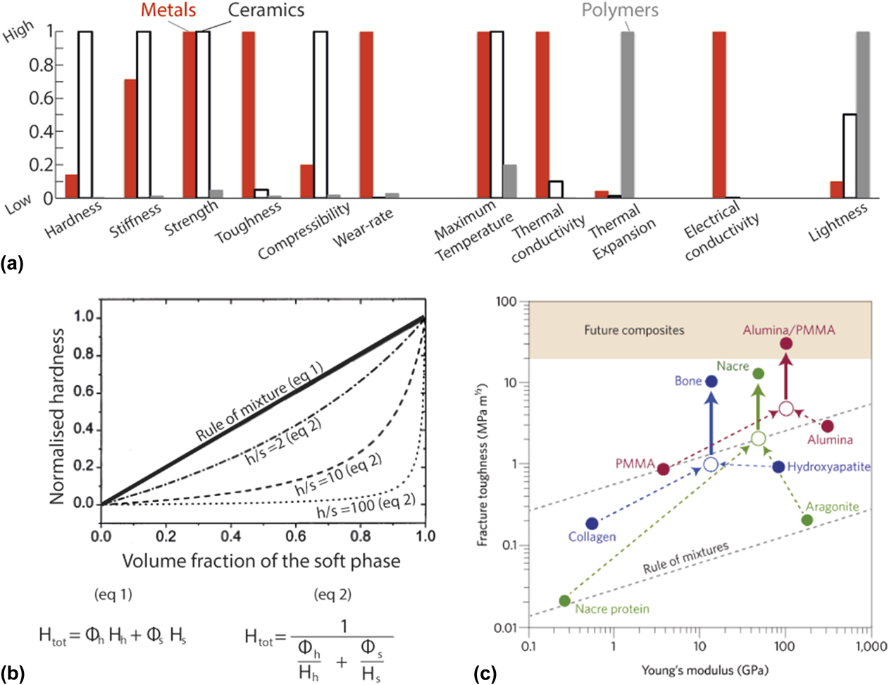
FIG. 1. Composite materials for combining properties. (a) Comparison of properties of homogeneous bulk metals, ceramics, and polymers on a scale of 0 to 1. (b) Evolution of the hardness in hard and soft composites as a function of the volume fraction ϕs of the soft phase. The subscripts h and s indicate the hard and soft phase, respectively. H h/H s is the ratio between the hardness of the two phases, written h/s in the figure. In (b) (eq 1) refers to the rule of mixture with iso-strain conditions, whereas (eq 2) refers to the isostress modelReference Kim1 (copyright © 2000 Elsevier). (c) Ashby plot representing the fracture toughness as a function of the Young’s modulus for biological and bio-inspired materials and their separate constituents, to emphasize the deviation from the rule of mixture in these compositesReference Wegst, Bai, Saiz, Tomsia and Ritchie2 (copyright © 2014 Springer Nature).
Indeed, the endo- and exo-skeletons of most species have parts made of composite materials with inorganic content well above 80% that display not only high mechanical performance but also multiple functions. Typically, these hard biomaterials provide the animals with either a protective shell, a structure, defense or attack appendices or grinding devices. What is unique in highly mineralized natural materials, and intrinsically correlated with their functions, is their internal hierarchical and heterogeneous microstructures. Indeed, at the microscopic scale, these materials have anisotropic crystals in the form of fibers or discs that are arranged into specific motifs, most of which are recurrent across species.Reference Fratzl and Weinkamer3–Reference Naleway, Porter, Mckittrick and Meyers5 These motifs, also called structural designs, are predominantly layered structures, uni- and bidirectional alignment and helicoidal arrangements. Figure 2 examplifies some of these features from the four larger groups of highly mineralized biocomposites, namely, calcium phosphate-based as in bones and teeth,Reference Maas and Dumont6 calcium carbonate-based as in seashells,Reference Sun and Bhushan7 calcium fluorapatite,Reference Bentov, Zaslansky, Al-Sawalmih, Masic, Fratzl, Sagi, Berman and Aichmayer8,Reference Bentov, Aflalo, Tynyakov, Glazer and Sagi9 sulfate,Reference Amini, Masic, Bertinetti, Teguh, Herrin, Zhu, Su and Miserez10 or magnetite as in some crustaceans—in particular the dactyl club of Mantis ShrimpsReference Amini, Masic, Bertinetti, Teguh, Herrin, Zhu, Su and Miserez10 and chiton teeth,Reference Weaver, Wang, Miserez, Tantuccio, Stromberg, Bozhilov, Maxwell, Nay, Heier, DiMasi and Kisailus11 and silica-based as in the glass spicules of sponges and diatomsReference Aizenberg, Weaver, Thanawala, Sundar, Morse and Fratzl12,Reference Wang, Zhang, Schröder and Müller13 [Fig. 2(A)]. All these animals present a hard shell or structure composed of a layered arrangement of mineral crystals [Fig. 2(B)]. Along with the microscopic structure, these materials display a macroscopic geometry and a chemical composition that are not left to chance, but that also exhibit typical features like chemical gradient or aerodynamic shape [Fig. 2(C)]. Structural properties resulting from these hierarchical structures usually combine high elastic modulus with high toughness [Fig. 2(D)]. These two properties are mutually exclusive in most synthetic ceramic–polymer composites due to the lack of microstructuring, as illustrated in Fig. 1(a).
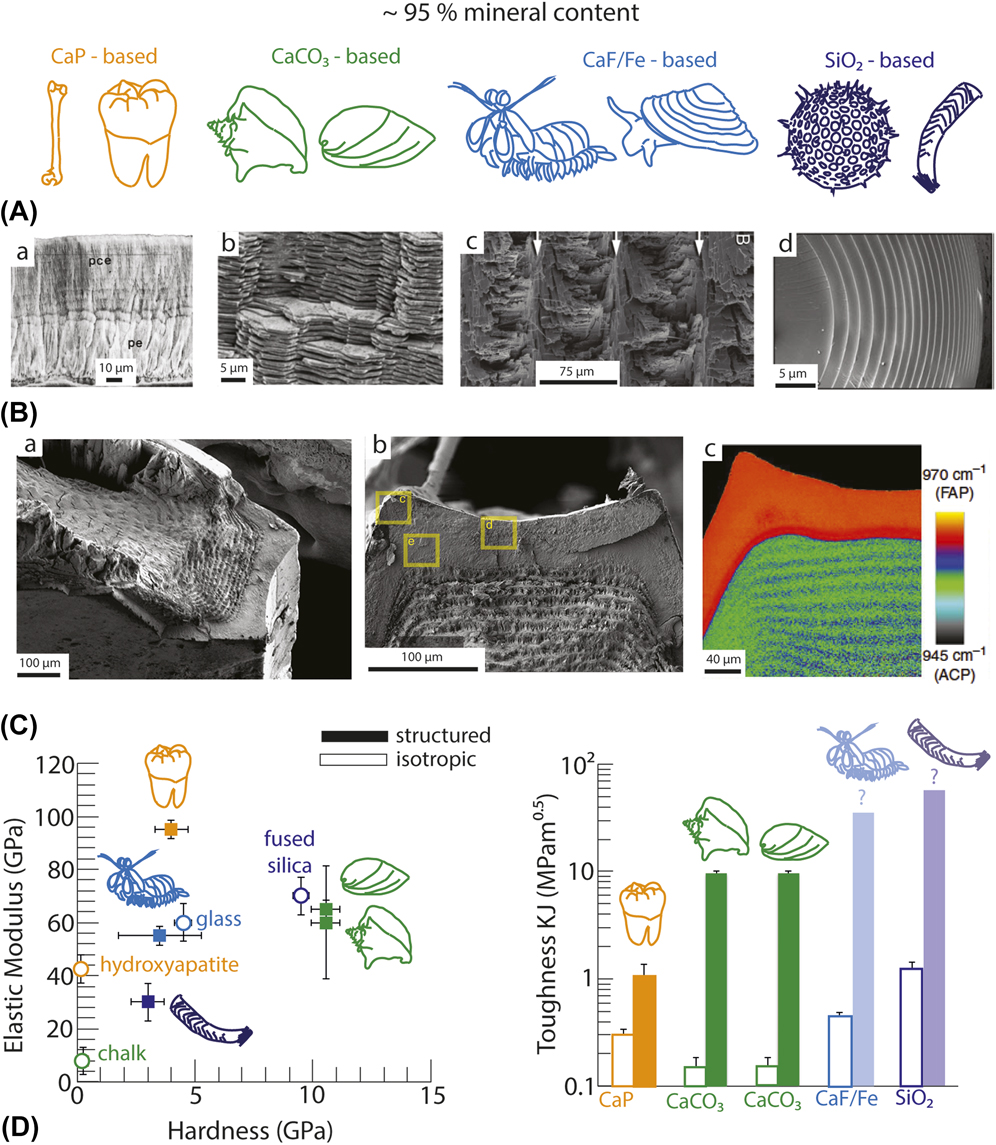
FIG. 2. The four main groups of highly mineralized biomaterials (A) and examples of recurrent microstructures (B): (a) layered organization of human teeth with hard outer enamel layer consisting of vertically aligned apatite rods and a softer dentin with horizontally aligned crystalsReference Maas and Dumont6 (copyright © 1999 John Wiley and Sons); (b) brick-and-mortar arrangement of aragonite (CaCO3) tablets in the nacreous layer of musselsReference Dastjerdi, Rabiei and Barthelat24 (copyright © 2012 Elsevier Ldt); (c) helicoidal orientations of mineral rods into a Bouligand structure with decreasing pitch from the dactyl club of stomatopodsReference Guarin-Zapata, Gomez, Yaraghi, Kisailus and Zavattieri31 (copyright © 2015 Acta Materialia); (d) layered structure of silica sheets in the spicules of the silica sponge Venus flower basket.Reference Aizenberg, Weaver, Thanawala, Sundar, Morse and Fratzl12 (copyright © 2015 AAAS) (C) (a, b, and c) Electron micrographs revealing the spatial organization of the dactyl club of the mantis shrimp and Raman map highlighting the local composition, where FAP stands for crystalline fluorapatite and ACP for amorphous calcium phosphate.Reference Amini, Masic, Bertinetti, Teguh, Herrin, Zhu, Su and Miserez10 (copyright © 2014 Springer Nature) (D) Mechanical properties of these biological families in comparison with materials of similar composition without microstructural architecture. Data for enamel,Reference Chai, Lee, Constantino, Lucas and Lawn26,Reference Devendra Bajaj, Nazari and Eidelman27 hydroxyapatite,Reference Devendra Bajaj, Nazari and Eidelman27–Reference Hoepfner and Case29 shell nacre,Reference Wegst, Bai, Saiz, Tomsia and Ritchie2,Reference Studart21,Reference Katti, Mohanty and Katti30 conch,Reference Kessler, Chateau and Heuer32,Reference Hou, Zhou and Zheng33 chalk,Reference Deleze34,Reference Brevik35 dactyl club,Reference Amini, Masic, Bertinetti, Teguh, Herrin, Zhu, Su and Miserez10,Reference Weaver, Milliron, Miserez, Evans-lutterodt, Herrera, Gallana, Mershon, Swanson, Zavattieri, DiMasi and Kisailus25 fluorinated glass,Reference Deubener, Höland, Höland, Janakiraman and Rheinberger36–Reference Kukiattrakoon, Junpoom and Hengtrakool38 glass sponge,Reference Woesz, Weaver, Kazanci, Dauphin, Aizenberg, Morse and Fratzl39,Reference Miserez, Weaver, Thurner, Aizenberg, Dauphin, Fratzl, Morse and Zok40 and fumed silica.Reference Miserez, Weaver, Thurner, Aizenberg, Dauphin, Fratzl, Morse and Zok40,Reference Xu, Quinn, Smith, Antonucci, Schumacher and Eichmiller41
Beyond pure mechanics, hierarchical structures also enable the implementation of multiple functions. First, due to their high strength and toughness, the overall thickness of highly mineralized microstructured materials to achieve protection and support can be significantly reduced. Porous structures that have such microstructures in the wall of their pores combine high mechanics and low weight, decreasing the energy cost for mobility. Glass sponges and trabecular bones are typical examples of such materials.Reference Aizenberg, Weaver, Thanawala, Sundar, Morse and Fratzl12,Reference Sullivan, Wang, Espinosa and Meyers14 Second, optical properties sometimes also result from the structural arrangement. This phenomenon is present in hard biomaterials under the form of structural iridescence as in the nacreous layer of seashellsReference Brink, van der Berg and Botha15 or of the optical fiber-like channelling in glass sponges’ spicules.Reference Aizenberg, Sundar, Yablon, Weaver and Chen16 Furthermore, specific properties like the magnetic response of the limpet teethReference Deng, Chin, Deng and Chin17 and in the beak of some birdsReference Falkenberg, Fleissner, Schuchardt, Kuehbacher, Thalau, Mouritsen, Heyers, Wellenreuther and Fleissner18 or the piezoelectricity of bonesReference Marino and Becker19,Reference Williams and Breger20 are allowed. Thanks to the microstructuring, these additional functions do not impede the mechanical properties. Finally, biological materials interact actively with the living cells that produce them. The synergistic effect of organized porosity and soft domains permits the diffusion of ions, nutrients, and molecules and provides the cells with signals and tools to grow and repair.
To replace the heavy metallic parts in the transport industry and to expand the field of applications of stiff and hard composites and ceramics, a viable strategy is to implement hierarchy into their structure. Recent developments have shown the potential of this path for producing stiff and hard composites enhanced with multiple properties.Reference Studart21,Reference Bermejo22 However, despite these remarkable advances, synthetic hierarchical composites still lack the level of intricacy that is so unique to natural materials.Reference Heuer, Fink, Laraia, Arias, Calvert, Kendall, Messing, Reike, Thompson, Wheeler, Veis and Caplan23 The difficulty in attaining such a level of control has long been a technical challenge due to the lack of fabrication tools. However, the past decade has witnessed a boom in the development of bottom–up manufacturing techniques that can address this issue. Bottom–up assembly techniques are well suited for hierarchically structuring composites as they imitate the role of living cells that locally synthesize and deposit materials during their growth. In synthetic fabrication paths, remote external fields have been used to manipulate colloidal particles during the fabrication. Combined with multiple processes and additive manufacturing, materials with control at several length-scales have been fabricated.
The ability to create stiff, strong, but also functional materials through the incorporation of bio-inspired architectures is attractive from a scientific point of view, but also for the industry and the general public. Indeed, having evolved over thousands of years for accomplishing their functions, it can be reasonably hypothesized that the natural structures are optimal structures for the specific constraints they are submitted to. Understanding the relation between external demands and internal structures could thus serve to adapt these natural model blueprints for the design of artificial composites submitted to relevant constraints. Furthermore, one key strategy observed in biomaterials is the spatial organization of a limited amount of widely available elements such as C, N, H, O, Fe, Ca, Mg, and P. Therefore, by reducing the chemical diversity in man-made materials, this approach can be anticipated to facilitate recycling and limit the use of rare and costly ingredients. Finally, if the structures exhibit enhanced mechanical properties while maintaining a high level of performance in other functions, the life-time of these objects will be extended. Hierarchically structuring hard and stiff materials therefore not only addresses mechanical restriction but also is likely to impact other aspects of the material’s utilization. In the long run, there is hope that the processes and materials developed for this goal will contribute to a more sustainable materials’ industry.
The aim of this paper is to review the recent advances in the fabrication of hierarchically structured and highly mineralized materials and their properties. This will facilitate the identification of possible pitfalls or necessary improvements to achieve the structures and goals set in this introduction. First, the pathways for reaching high mineralization in materials will be described and the stages of the processes at which controlled hierarchical structuring can be implemented will be highlighted. Then, a theoretical description of anisotropic particle manipulation with external fields will be given at the single particle level, along with the typical practical setups used. In the context of highly mineralized materials, I will then tackle the experimental constrains that are faced in the controlled manipulation of particles in concentrated suspensions. Following, I will describe some of the main methods used to achieve hierarchical and heterogeneous architectures in highly mineralized composites. These fabrication strategies will be compared in terms of flexibility in particle orientation and position, but also chemical variation and macroscopic shaping. Scale-up in time and dimensions will also be discussed to evaluate their potential for industrial production. Finally, some of the properties of these architectured materials will be reported. These examples will broaden or improve our view that these new materials with unprecedented functionalities can indeed pave the way for significant changes in the manner we design devices and structures. With this knowledge, it should be possible to determine the state of the art and find out the remaining challenges for new multifunctional highly mineralized materials, and/or new processes.
II. REACHING HIGHLY MINERALIZED STRUCTURES
To determine at which step microstructuring via the application of external fields can be implemented in a process, it is important to first be familiar with the common paths for the fabrication of highly mineralized composites and ceramics (Fig. 3). To broaden the discussion, I will tackle materials containing a minimum of 50% in volume of inorganic matter, but I will consider only bulk materials, and not surface coatings and nanofabrication.

FIG. 3. Example pathways to reach high mineral content in bulk materials: mineralization on an organic template (a), preceramic polymer route (b), temperature or pressure-aided sintering (c) and composite mixing path (d). (a) Example of the mineralization of a wood cell by incubation in ionic solutionReference Merk, Chanana, Keplinger, Gaan and Burgert42 (copyright © 2015 RSC). (b) Schematics of the preceramic polymer route. (c) Description of the principles of cold sintering process at ambient conditions of temperature under elevated pressure P Reference Bouville and Studart43 (copyright © 2017 Nature Springer). (d) Fabrication of a particulate-reinforced resin by mixing, degassing, and castingReference Libanori, Erb and Studart44 (Copyright © 2013, ACS). (e) Comparison of the three main routes in terms of time and mineral content. The pink area indicates where structuring through the use of external fields is possible.
Four major pathways exist to obtain bulk and highly mineralized materials:
(i) Mineralization by ion precipitation and crystallization onto an organic template [Fig. 3(a)]. This process displays close similarity to natural biomineralization events.
(ii) Conversion of preceramic polymers into ceramics after pyrolysis. If the shrinkage is appropriately controlled, the organic material directly transforms into a dense ceramic [Fig. 3(b)].
(iii) Densification by following a ceramic processing path where intergranular necking occurs by thermal and/or pressure-enhanced diffusion of atoms and their redeposition on neighboring particles [Fig. 3(c)].
(iv) Mixing and consolidation by polymer composite processing. The mineral content is determined at the initial stage by the amount of inorganic particles introduced into a liquid organic matrix that is subsequently consolidated [Fig. 3(d)].
Mineralization is used to convert an organic template into a mineral while preserving the shape and structure of the templateReference Nudelman and Sommerdijk45 [Fig. 3(a)]. Typically, the initial organic material consists of a synthetic organic polymer or a native biological material that already possesses a hierarchical structure. This template is then left to soak in a solution containing the ions that will deposit onto it to form the mineral. Often, mineralization is enhanced by a higher temperature and can be triggered by acidic organic groups, for example, from negatively charged polymers, peptides, proteins, or amino acids.Reference Van Bommel, Friggeri and Shinkai46,Reference Kröger and Sandhage47 These molecules have the role of adsorbing the metal cations and to dictate the crystalline orientation and the shape of the minerals in predetermined ways. In some cases, the organic template is used as a scaffold for living cells to further promote mineral deposition in in vitro and in vivo conditions.Reference Boskey and Roy48 Despite the long time needed to convert the entire template into a bulk mineral, from days to weeks and months, the strategy has the unique advantage of preserving the microstructure initially built or encoded in the template.Reference Merk, Chanana, Keplinger, Gaan and Burgert42,Reference Liu, Kim, Dai, Li, Khan, Pashley and Tay49 Since organic processing can be fast and highly diverse, intricate hierarchy can be already predesigned within the matrix. In addition, slow and thermodynamically-controlled mineralization might allow for the obtention of mineral phases close to those found in natural materials.Reference Bahn, Jo, Choi and Cha50 Many studies show that some mineral phases, in particular, nonfavorable amorphous clusters, could play a non-negligible role in the outstanding properties of some highly mineralized biomaterials. The materials that result from this path therefore exploit the hierarchical structure from the template with the mechanical benefits from the mineralization and can combine multiple properties. One illustration is the fabrication of enhanced stiffness and fire retardancy in partially calcified wood.Reference Merk, Chanana, Keplinger, Gaan and Burgert42 Finally, direct mineralization from ionic solutions is a low-energy process and a green strategy.
The use of preceramic polymers as precursors for the ceramic phase can be regarded as a faster path for the conversion of an organic template into a mineral [Fig. 3(b)]. The large majority of these precursors are silicon-based polymers with repetitive sequences of Si–C, Si–O, Si–N, or Si–N=C=N bonds.Reference Colombo51 After pyrolysis at temperatures higher than 800 °C, these polymeric sequences convert to SiC, SixCyOz, and SixCyNz, respectively. Other matrix chemistries are obtainable by modifying the polymer precursor accordingly or by the addition of filler material or chemical additives.Reference Colombo51 In addition, polymer degradation and mineral phase formation can lead to phase separation and chemical flux within the matrix. Despite being 100% organic at the initial stage, fully dense ceramics can be obtained by this route. This is achieved by overcoming the two major hurdles, namely, the shrinkage occurring from the degradation of the organics and the pressure built-up from gas release. Spark plasma sintering and addition of fillers are typically used to achieve 100% dense ceramics.Reference Mazo, Palencia, Nistal, Rubio, Rubio and Oteo52,Reference Picot, Rocha, Ferraro, Ni, D’Elia, Meille, Chevalier, Saunders, Peijs, Reece and Saiz53 Furthermore, this processing approach enables the use of polymer shaping technologies. Recent advances in 3D printing show that through this route, customized parts for micro-electromechanical systems, propulsion components, or thermal protective systems can be fabricated.Reference Eckel, Zhou, Martin, Jacobsen, Carter and Schaedler54
Densification via ceramic processing is the well-established and common pathway to reach high mineral content in bulk and controlled shapes [Fig. 3(c)]. All ceramic processing techniques start with inorganic powders that are either pressed to form a pellet ready for high temperature sintering or de-agglomerated and resuspended in an appropriate liquid to form a slurry. In this latter case, agents can be incorporated to increase or decrease the viscosity to facilitate casting into a mold, extrusion or lamination by tape-casting. All these methods are used for shaping while the powder from the slurry compacts in parallel by slow liquid removal. This consolidation is achieved by pressing, air- or capillary-drying through the pores of a mold, coagulation by pH change or rising ionic strength, or the use of a gelling organic phase.Reference Ring and Ring55 The body formed after consolidation, termed the green body, contains an assembly of powder particles with multiple contact points. These contacts are of primary importance for the necking and densification as they allow the diffusion of atoms from one particle to the other and the thickening of these necks into grains. This step, the sintering, is controlled by the heating rate and dwell temperature, typically above 1000 °C and below 2000 °C, and can be accelerated by the application of pressure and doping agents. Due to the high temperatures involved, no organic phase remains at the end of the process. To enable the infiltration of a soft phase, an interconnected porous network has to be originally programmed either by the formation of bubbles or by steric hindrance between the mineral grains restricting the compaction.Reference Minas, Carnelli, Tervoort and Studart56,Reference Studart, Gonzenbach, Tervoort and Gauckler57 Only recently, several studies have explored this densification process at ambient temperature in hydrated conditions and under high pressure, referred to as cold sintering. The presence of liquid under pressure enhances the dissolution and reprecipitation of ions at the neck between adjacent grains.Reference Bouville and Studart43,Reference Guo, Guo, Baker, Lanagan, Kupp, Messing and Randall58 In addition, depending on the degree of mineralization aimed at, care should be taken to determine the optimum conditions of sintering as internal expansion or compaction due to crystal lattice phase transformations may generate cracks. This is often observed in calcium phosphate-based ceramics.Reference Lee and Freer59 Ceramic processes have been adapted to offer precise control over the macroscopic shape down to very fine details. However, the internal grain arrangement is usually random and isotropic, in the form of a homogeneous distribution of spherical grains of predictable dimensions.Reference Lee and Freer59
The fourth path for obtaining highly mineralized composites is a traditional composite path where an organic matrix is reinforced by elongated fibers or particles [Fig. 3(d)]. Composites based on elongated fibers are widely used in the industry. These are prepreg composite laminates where glass fibers are embedded in a thermoset resin in the form of sheets. These sheets, or laminates, are then placed by hand into several layers with similar or varied directions of fiber orientations. Once the stack of sheets is ready, they are pressed at the temperature of curing of the polymer to consolidate the assembly. The structure obtained in these composite stacks is reminiscent of the layered bio-inspired structural design with single or multiple orientations. However, shaping and out-of-plane orientations are not permitted by this method. Therefore, the use of small size fiber or particulate reinforcements has been introduced in new formulations. Mineral oxides are particularly interesting due to their low cost, large abundance, and facile availability. In this case, the preparation of the composite is very similar to the initial stage of the ceramic processing where particles are dispersed into a liquid phase that is subsequently casted and consolidated by other means. Finally, this describes also the initial stage of the preceramic precursor path where filling particles are added to reduce the shrinkage and the pressure build-up during the firing.
The four pathways for highly mineralized materials described here are able to offer controlled macroscopic shape [Fig. 3(e)]. Very high level of mineralization up to 100% can be obtained following the preceramic precursor and ceramic pathways, whereas the composite method has a degree of mineralization determined by the amount of particles placed into the liquid matrix at the initial stage of the process. Mineralization, on the other hand, can potentially lead to all ranges of mineralization depending on the time at which the material is removed from the ionic solution. Mixed pathways are potential solutions to combine high mineralization with short time fabrication. In this respect, a concrete example will be provided in the part 5 of this review. Furthermore, the processes described until here do not allow for microstructuring of the materials in neither directed nor programmable ways. Indeed, mineralization does provide hierarchical structures but these are commanded by the template. Preceramic polymers and fillers are homogeneously mixed to prevent anisotropic shrinkage and phase transformations during firing. Ceramic path may offer hierarchy through foaming formulations. However, the microstructures obtained strongly deviate from the examples provided in Fig. 2 as they will feature spherical pores with homogeneous distributions and orientations of grains.Reference Minas, Carnelli, Tervoort and Studart56 Finally, the composite path involves mixing and casting, which are methods leading to isotropic structure of micron-sized particles unless specific phase separation occurs. However, all four high mineralization routes have a stage of low mineralization. At this stage, mineral particles are embedded in a fluid or a soft matrix and can potentially be manipulated via external fields to purposely control their orientation and position.
III. EXTERNAL FIELDS TO MANIPULATE SINGLE PARTICLES
Single particles suspended in a liquid can be manipulated in position and in orientation by the use of external fields. Spherical particles do not display orientation since they are isotropic (0-D), whereas rod-like particles can exhibit an orientation in one dimension (1-D). 2-D shaped particles, in the form of discs or obloids, have two perpendicular main axis orientations and therefore can display uniaxial or biaxial alignments. Since these 2-D particles have the largest degree of possible orientation, this case will be largely discussed in the remainder of the paper. The 1-D and 0-D particle cases can be deduced by assuming symmetries in the system. 3-D shaped particles have infinite possibility of shapes, axis number, and orientations but are seldom available in large quantities and are less likely to be used to fabricate bulk and highly mineralized materials. Despite the evidence that such building blocks offer a large interest to yield new deformation mechanisms and properties,Reference Siegmund, Barthelat, Cipra, Habtour and Riddick60 their orientation in space will need to be considered for each individual geometry and is beyond the scope of this review.
The external fields that can be utilized to manipulate 2-D particles in space can be sorted into three families, namely, mechanical, electrical, and magnetic fields (Fig. 4). Particles can also be manipulated by optical means. In the context of highly mineralized composite processing, optical processes are hindered due to multiple scattering and opacity of suspensions at high solid loadings. The choice of field to apply will mostly be determined by the property mismatch between the particle and its medium. A difference in density would preferentially allow the use of mechanical fields, in polarization of electric fields and in magnetic susceptibility of magnetic fields. The theoretical description and setups presented in the following can be generalized to particles of all sizes. However, the description is limited here in terms of manipulation of 2-D colloidal particles that have two dimensions in the micrometer range and a third dimension in the submicrometer or nanometer range. This type of particles has the specificity of being not completely dominated by Brownian motion. This is primarily to justify that the thermal energy can be neglected in the energy balance at equilibrium.Reference Erb, Libanori, Rothfuchs and Studart62 The expressions of the torques that these fields apply to anisotropic particles (Tables I and II) result from a thermodynamic argument: the particle’s motion is driven by the necessity to place the particle in its minimum energy. On the other hand, the forces that the center of mass of the particle undergoes derive from the gradient of the external field. A particle exposed to a field with homogeneous strength distribution will thus only orient, while heterogeneities in the field’s intensity will combine rotation with translation of the particle.Reference Demirörs, Pillai, Kowalczyk and Grzybowski68

FIG. 4. Anisotropic particle manipulation by external fields: namely (a) pressure, (b) electric, and (c) magnetic fields. (a) Gravity, shear stresses, and acoustic standing waves can be used to rotate anisotropic 2-D particles via a torque T and to displace the center of mass of the particle via a force F. (b) Static electric fields can align and attract charged particles toward the electrode of other sign. Using electrode array, positively and negatively charged particles can be located selectively. (c) For particles with a magnetic susceptibility χp superior to that of the fluid χf, magnetic fields will align and orient them. Similar to the electrode array, an array of magnetic dipoles will locally align and orient particles.
TABLE I. Theoretical description of the forces and torques applied by pressure fields.

TABLE II. Theoretical description of the forces and torques applied by electric and magnetic fields.

The experimental setups used to manipulate particles using external fields are schematized in Fig. 4. Mechanical or pressure fields are applied using gravitational forces, shear or acoustic waves [Fig. 4(a)]. 1-D vertical alignment of rods can occur during sedimentation by the combined effect of gravitational force and shear at the surface of the anisotropic particle. On the contrary, gravity leads to spontaneous 2-D horizontal alignment for disc-like particles due to their large surface area. The effect of gravity on anisotropic particles is accelerated and enhanced by increasing the density mismatch between the background fluid and the particle and for low viscosity fluids.Reference Behr, Vainio, Müller, Schreyer and Schneider72 Shear fields, spontaneously generated during motion of particles by other pulling forces like sedimentation, can also be generated by fluid flow. At low Reynolds numbers in a small channel, i.e., for  ${\mathop{\rm Re}\nolimits} = {{{\rho _{\rm{f}}}{v_{\rm{f}}}L} \over \mu } \ll 1$, turbulence is negligible and streamlines parallel to the walls arise.Reference Mueller, Llewellin and Mader73 This type of flow will force anisotropic micron-sized particles to align their longest dimensions in line with the flow. Couette rheological setups where a liquid is sandwiched between a static plate and a mobile plate give rise to this type of laminar flow. Extrusion through a pipe or the spreading of a liquid or paste with a doctor-blade, method called tape-casting, generates laminar flows with horizontal and parallel streamlines as well.Reference Watanabe, Kimura and Yamaguchi74 Mechanical external fields by acoustic pressure waves are used to simultaneously control particle position and orientation. This is realized by propagating a pressure wave generated by a piezoelectric actuator working at frequency from 1 to 50 MHz in a cavity of defined dimensionsReference Garbin, Leibacher, Hahn, Le Ferrand, Studart and Dual64 [Fig. 5(A)]. When the wave travels through the cavity, it is reflected at the wall on the other side and travels backwards, where it is reflected again at the other cavity wall. There is a specific frequency of the piezoelectric excitation at which the pressure waves traveling in the suspension in the channel will superimpose and cancel each other at distances proportional to the wave length. These points are the pressure nodes. By contrast, the waves will supplement each other at other distances, the pressure anti-nodes. In the channel, this will be equivalent to having a static single wave and this is therefore called a standing wave. When this arises, the particle’s center of mass will be attracted to the pressure nodes and orient perpendicular to the waves [Fig. 5(B)]. Varying the cuvette geometry, the piezoelectric stimulator frequency and the amplitude allows for the generation of programmable patterns of pressure nodes and antinodes and therefore for controllable position and orientation of anisotropic particles in 3 dimensions.Reference Haake, Neild, Radziwill and Dual75
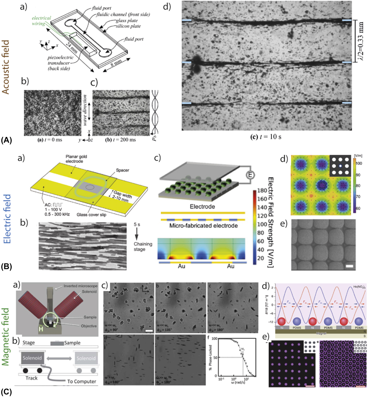
FIG. 5. Examples of experimental set-ups to manipulate particles in dilute suspensions via external fields. (A) (a) Acoustic waves generated by a piezoelectric actuator can create a standing pressure wave in a channel of finite dimensions; (b–d) Anisotropic particles suspended in the channel will orient and concentrate at the pressure nodes of the waveReference Garbin, Leibacher, Hahn, Le Ferrand, Studart and Dual64 (Copyright © 2015 ASA). (B) (a and b) AC electric fields generated by applying an AC voltage will orient anisotropic particles along the field linesReference Velev, Gangwal and Petsev69 (copyright © 2009 RSC); (c–e) arrays of electrodes alternate the electric field strength in the plane and allows for the local concentration of particles in selected areasReference Demirors, Courty, Libanori and Studart70 (copyright © 2016 PNAS). Scale bars 20 µm. (C) (a and b) two set-ups to create rotating magnetic fields and (c), platelets’ response to rotating fields of increasing frequency of rotation showing the biaxial alignment at high frequency, scale bar 20 µmReference Erb, Segmehl, Schaffner and Studart61,Reference Erb, Segmehl, Charilaou, Löffler and Studart71 (copyright © 2012 RSC, copyright © 2013 RSC); (d and e) arrays of magnetic dipoles in the form of virtual magnetic mold is used to concentrate magnetic and nonmagnetic particles at specific areas in the planeReference Demirörs, Pillai, Kowalczyk and Grzybowski68 (copyright © 2013, Springer Nature). Scale bars 10 µm.
Electric fields are generated by applying a voltage between two electrodes deposited at the edge of a dielectric material such as an organic soft matrix or a liquid. When polarized or polarizable particles are present in this dielectric, they will respond to the field by aligning along the streamlines and migrating towards the electrode of opposite polarity. A convenient way to polarize mineral particles is to suspend them in a water-based liquid where surface charges emerge. The surface charge of the particles will result from the exchange of ions and electrons with the surrounding water in the Debye layer. The surface charge can be controlled and modified by adjusting the pH of the solution, the ionic strength, or by employing charged surfactant molecules that will adsorb onto the surface of the particles. When applying a DC electric field to an aqueous solution, electro-osmotic effects will lead to the migration of the charged components dispersed in the liquid, meaning the particles and also the surrounding ionic constituents. To avoid this flow and maintain a homogeneous concentration of ions in the suspension, AC fields at frequencies between 50 kHz and 1 MHz are necessary.Reference Velev, Gangwal and Petsev69,Reference Demirors, Courty, Libanori and Studart70 Under these conditions, anisotropic particles, with homogeneous charge, will align their long axis along the field direction [Fig. 5(C)]. In addition, the particles surface charge is likely to fluctuate to form an electrical dipole. When this occurs, particle chains parallel to the field lines form in the liquid.Reference Belijar, Valdez-Nava, Diaham, Laudebat, Jones and Lebey76 To control the positioning of particles in complex patterns, arrays of positive and negative electrodes can be used to modulate the electric field strength in 2-D and in 3-D. In this case, positively charged components will be dragged toward the negative electrodes while the negatively charged components will be attracted to the positive onesReference Demirors, Courty, Libanori and Studart70 [Fig. 5(D)].
Magnetic fields can be produced by permanent magnets, with a range from 3 mT (fridge magnet) to 1 T for 10 × 10 × 10 cm3 large rare-earth magnets, or from electromagnets. Electromagnets are electric coils that can generate magnetic fields from 0.1 mT up to 45 T for super- and supraconductive electromagnets with helium cooling. Without demanding cooling and intense electric fields, traditional electromagnets of diameter 9 cm and length 10 cm achieve 10–300 mT over an area of 10 × 10 cm2 under 10 mA. In addition, magnets have a south and a north pole. The field lines of each magnet, linking the two poles, are therefore highly dependent on the magnet’s geometry. In the case of electromagnets, the field within the coil has the advantage to be highly homogeneous with parallel lines of similar magnetic strength at the core of the coil. When a particle has a magnetic susceptibility different from that of its surroundings, it will align along the field lines and be attracted to the opposite pole, similarly to what is observed in electric fields. Since every atom possesses electrons and thus a magnetic spin, all matter can align with a magnetic field.Reference Suzuki, Uchikoshi and Sakka77,Reference Sakka and Suzuki78 However, the strength required might be enormous and call for supraconducting magnets. To be able to use standard magnets with mild field strength, it might be necessary to modify the chemistry of the particle. Inorganic materials with low magnetic susceptibility can be coated with a thin layer of ferromagnetic material such as iron oxide.Reference Niebel, Heiligtag, Kind, Zanini, Lauria, Niederberger and Studart79 Another strategy commonly used is to physically adsorb superparamagnetic iron oxide nanoparticles (SPIONs) onto the surface.Reference Erb, Libanori, Rothfuchs and Studart62 These nanoparticles, below 20 nm in diameter, are constituted of only one single magnetic domain and consequently respond ultra rapidly to magnetic fields. As commented earlier, 1-D microparticles can easily align their longest dimensions with the 1-D field lines. To align 2-D microparticles biaxially, it is necessary to apply a 2-D field. In the case of magnetic fields, this can be created by rotating the magnet or the sample above a critical frequency f c.Reference Erb, Segmehl, Schaffner and Studart61,Reference Erb, Segmehl, Charilaou, Löffler and Studart71 Indeed, for f < f c, the 2-D particle will rotate along with the field at the same frequency f. However, at f > f c, it is more energetically favorable for the particle to remain in the same position, aligned in the plane of rotation of the magnetic field, than to rotate and drag a lot of fluid at each rotation [Fig. 5(E)]. In the case of inorganic 2-D particles coated with SPIONs of diameter d,  ${f_{\rm{c}}} = {{{\mu _0}\chi _{\rm{p}}^2{H^2}} \over {18f\eta \left( {{\chi _{\rm{p}}} + 1} \right)}}\left[ {{{\left( {a + d} \right){{\left( {b + d} \right)}^2}} \over {a{b^2}}} - 1} \right]$.Reference Erb, Segmehl, Schaffner and Studart61,Reference Erb, Segmehl, Charilaou, Löffler and Studart71 Furthermore, similar to electric fields, particles of high magnetic susceptibility will be attracted toward areas of high magnetic fields. The spatial modulation of the magnetic field strength can thus be controlled by fabricating arrays of magnetsReference Bjørk, Smith and Bahl80 or via the use of virtual magnets where a ferromagnetic pattern will serve to concentrate and localize the magnetic fieldReference Demirörs, Pillai, Kowalczyk and Grzybowski68,Reference Le Ferrand, Bolisetty, Demirors, Libanori, Studart and Mezzenga81 [Fig. 5(F)]. Finally, magnetic dipoles can also form in particles with ferro- and ferrimagnetic properties, leading to the formation of unidirectional chains parallel to the magnetic field lines.Reference Li, Peng and Chen82
IV. MANIPULATION OF PARTICLES IN CONCENTRATED SUSPENSIONS FOR HIGH MINERALIZATION
External fields allow for the manipulation in orientation and position of particles in a liquid. In concentrated suspensions, however, interparticle interactions might hinder the manipulation (Fig. 6). First, I will comment on the design freedom enabled by these external fields at the single particle level and extend the discussion to highly loaded particle suspensions. Then, I will discuss the experimental requirements for achieving mineralized materials with organized microstructure.

FIG. 6. Comparison of the DOF for each external field applied to a suspension of disc-like particles, namely pressure  $\vec{P}$, electric $\vec{E}$, and magnetic $\vec{B}$, as a function of the volume fraction of particles to manipulate.
From the above discussion, mechanical fields do not require functionalizing or chemically varying the particle composition if the strength applied is sufficiently high. However, it should be repeated that it is the mismatch between the properties of the particles and their surrounding fluid that enables the manipulation. Therefore, it is equally viable to modify the chemistry of the fluid or of the particle to manipulate any micron size object with an external field. To compare the potential of each external field to manipulate micron-sized inorganic particles, I compare the control in orientation and in position for 2-D disc-like particles. All fields are able to orient particles in the direction of the field. In the case of gravitation and shear, this alignment is primarily horizontal for 2-D particles, whereas it can be horizontal and vertical for 1-D electric and 1-D magnetic fields. Biaxial alignment is realized horizontally in gravitational and shear fields due to the 2-D geometry, and vertically in acoustic fields. In 2-D magnetic fields, generated by rotating magnets, the biaxial alignment can be in any direction. Similarly, perpendicular pairs of electrodes can create 2-D electric fields to orient sheet materials in space.Reference Leunissen, Vutukuri, Hall and Blaaderen83 Furthermore, the control of the position of the center of mass of the particles is achieved in all strategies by spatially varying the strength of the field. To conclude, it is remarkable that this manipulation is determined only by the difference between the intrinsic properties of the particles and the fluid. Therefore, it is also possible to manipulate mixtures of particles with different chemistry, shapes, and dimensions within the same external field.Reference Demirörs, Pillai, Kowalczyk and Grzybowski68 In some particular cases, it might even be beneficial to couple different external fields to have access to an even greater range of design freedom.Reference Martin, Riederer, Krebs and Erb63,Reference Demirors, Courty, Libanori and Studart70,Reference Bharti, Kogler, Hall, Klapp and Velev84 For example, 2D vertical alignment of discs can be realized by combining 1D electric field with a perpendicular 1D magnetic field.Reference Nguyen, Contera and Garc66
To create composite materials with significant mineral content, the manipulation of the particles has to take place already in concentrated suspensions [Fig. 3(d)]. With the exception of magnetic fields with ultra high strength that are able to orient ceramic grains by providing the atoms with an energy higher than their thermal energy,Reference Suzuki, Uchikoshi and Sakka77,Reference Sakka and Suzuki78 for aligning particles, it is necessary for each individual particle to have the possibility to rotate and move. Therefore, at the stage where the external field is applied, the radii of gyration of the particles should not overlap. Fig. 6 shows the degree of freedom (DoF) enabled by the external fields as a function of the volume fraction of suspended particles. To draw a meaningful comparison, 2-D particles of aspect ratio around 40 that have been largely used in the literature are considered.Reference Garbin, Leibacher, Hahn, Le Ferrand, Studart and Dual64,Reference Demirörs67,Reference Erb, Segmehl, Charilaou, Löffler and Studart71,Reference Bouville, Maire and Deville85 It is expected that particles with larger aspect ratios exhibit similar trends at lower volume fractions. Indeed, the viscosity of the system, the major hurdle, increases drastically with the aspect ratio. The particles are also required to be well-dispersed and without attractive interactions that might destabilize the suspension. With this in mind, acoustic orientation and positioning is hindered above volume fractions of around 10 vol%.Reference Garbin, Leibacher, Hahn, Le Ferrand, Studart and Dual64 Indeed, the increase in solid loading increases the number of liquid–particle interfaces that scatter the acoustic wave. The suspension therefore becomes “acoustically opaque” as the concentration of particles increases. Acoustic streaming or simply absence of ordering are manifestations of this phenomenon. Electric fields, pressure fields from gravity or shear, and magnetic fields of low strengths are limited by the increase in viscosity that accompanies the increase in volume fraction. The percolation of colloidal particles past a certain concentration threshold forms a jammed network where collision and short-range attraction prevent the motion of single particles. This threshold will depend on the aspect ratio of the particles and can be tuned by controlling the electrostatic repulsion between the particles. Unstable colloidal suspension and attraction between the particles would indeed lower drastically the threshold. To a certain extend, the system can be artificially unjammed by the application of another mechanical field via vibrations.Reference Libanori, Erb and Studart44 The case of shear-induced alignment also deserves more attention as shear is often more efficient in an optimal concentration range. If the concentration of particles is too low, the thick layer of liquid separating the plane of external shear and the particle will dissipate the energy. As a result, there will not be any transfer of stress and strain to the particle and no alignment will be seen. By contrast, too high concentration, yet below the jamming, might be driven to a jammed state upon application of a shear.Reference Peters, Majumdar and Jaeger86 The suspension will thus exhibit a shear-thickening effect, probably caused by hard collisions of particles under motion.
Finally, one last requirement to obtain a highly mineralized material with orientation and position control is to maintain the microstructure as the material densifies. Indeed, the forces involved during densification, for example, from external pressure or capillary forces, might overcome the forces from the external fields and modify the microstructural arrangement. If the strategy adopted follows the composite path [Fig. 3(c)], the curing and setting of the matrix at the end of the manipulation will be sufficient to consolidate the structure without disturbing the alignment. The use of thermosetting polymers is particularly suited in this case as the solution of monomers is initially liquid, permitting the manipulation, and increases in viscosity as the curing occurs. Temperatures below 60 °C are compatible with electric, magnetic, and mechanical fields. Above 60 °C, electrodes might behave differently and the magnet might also loose its magnetization. UV-curing is another efficient way but is usually not compatible with magnetic manipulation in concentrated systems. Indeed, iron oxide and other ferromagnetic materials such as nickel or cobalt absorb in the UV. In high concentration, these elements will inhibit the polymerization. Gelling systems triggered by time through the addition of catalysts or via enzymatic reactions are also good methods to maintain the microstructure.Reference Bargardi, Le Ferrand, Libanori and Studart90 Finally, for systems where curing is triggered by the addition of chemicals and their diffusion through the matrix, the experimental set-up might require fine tuning so that the addition of the agents is slow enough and do not disturb the assembly, for example, due to turbulence. For highly mineralized materials fabricated along the ceramic path, the methods mentioned above can be applicable for the obtention of the green body. In cases where the organic phase content is at a minimum, an optimum in concentration should be found so that the particles can be manipulated via the external fields and maintain their structure after removal of the liquid phase. To fight against capillary forces rising during drying or slip-casting, the particles should form already a dense and jammed structure once the field is removed.Reference Le Ferrand, Bouville and Studart93 This can be realized by adjusting the initial concentration to be close to the jamming threshold, or by the addition of nanoparticles that will jam quickly after removal of the field.Reference Kokkinis, Schaffner and Studart88 Finally, ceramic processing often uses pressure to push the mineral content to its maximum. When a ceramic green body contains a microstructure, uniaxial or isostatic pressing will lead to a denser horizontally oriented construct. To circumvent the need for external pressing, the suspension’s composition can be modified to allow for grain growth and densification by temperature sintering only. This approach, called templated grain growth, relies on the preferential diffusion from small grain onto large grains.Reference Messing, Trolier-McLinstry, Sabolsky, Duran, Kwon, Brahmaroutu, Park, Yilmaz, Rehrig, Eitel, Suvaci and Seabaugh92 As such, mixtures of anisotropic microparticles and spherical nanoparticles can be densified without pressure. In this scenario, the 2-D shaped particles are oriented via shear or magnetic field in a concentrated, yet liquid, suspension of nanoparticles of similar chemistry. By adding gelling agents or simply by drying, the nanoparticles will form a network that will maintain the microstructure.Reference Kokkinis, Schaffner and Studart88,Reference Bargardi, Le Ferrand, Libanori and Studart90 During the sintering step at a high temperature, the 2-D particles used for microstructuring will behave as a template for the nanoparticles to grow and merge with. The resulting ceramics are dense above 80% and display grain orientations in the same directions as the initial 2-D particles. In this particular case, texturation by orientation of the particles correlates with the crystallographic orientation. This occurs only when the templates display well-defined crystallographic orientation.
V. ACHIEVING HETEROGENEOUS ARCHITECTURES
External fields are powerful means to manipulate particles in liquid or in mildly concentrated suspensions. This manipulation can be coupled with established processes to achieve microstructuring, high concentrations with controllable chemistry, shape, and dimension. In the following, examples of such processes are given and their principles and some of the possible structures obtained are described. The methods discussed are tape-casting, freeze-casting, slip-casting, and 3D printing.
Layering material is a straightforward procedure to build a heterogeneous and hierarchical material (Fig. 7). Tape-casting is a method of choice as it allows control of the thickness and the application of a mechanical shear field to orient particles horizontally [Figs. 7(a) and 7(b)]. The method is highly flexible. Indeed the composition, structure, and density can be varied in each layer as well as the number, thickness, and sequence of layers. As such, alignment in thin layers can be achieved in composites up to 40% of 2-D particlesReference Bonderer, Studart, Woltersdorf, Pippel and Gauckler91 [Fig. 7(b)] but also in dense ceramics.Reference Pavlacka, Bermejo, Chang, Green and Messing94,Reference Messing, Poterala, Chang, Frueh, Kupp, Watson, Walton, Brova, Hofer, Bemejo and Meyer96,Reference Chang, Bermejo, Sevecek and Messing97 Figures 7(c) and 7(d) present polished cross section of layered alumina–aluminum oxide–ceramics with density above 90% in volume that was prepared by sequential layering of slurries containing alumina nanoparticles and alumina 2-D particles to serve as templatesReference Pavlacka, Bermejo, Chang, Green and Messing94 (see part 4 for details about templating). Delamination is typically prevented by diffusion transport across the layers. This diffusion can be triggered thermally as in the case of ceramics or thermosetting matrices or via the use of solvents to locally dissolve and disentangle thermoplastic matrices. In addition to the mechanical field applied by shear during tape-casting, the method can also be combined with external fields such as magnetic fields.Reference Bargardi, Le Ferrand, Libanori and Studart90,Reference Poterala, Meyer and Messing98 For example, by co-mixing alumina nanoparticles with alumina 2-D particles coated with SPIONs, out-of-plane alignment was successfully realizedReference Bargardi, Le Ferrand, Libanori and Studart90 [Figs. 7(e)–7(g)].
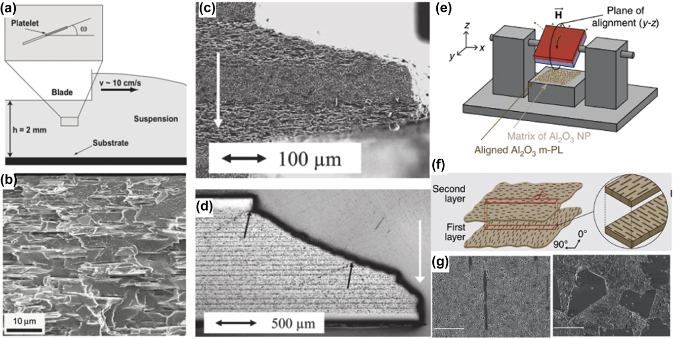
FIG. 7. External fields applied to tape-casting: (a) Schematics of the tape-casting methodReference Bonderer, Studart, Woltersdorf, Pippel and Gauckler91 (copyright © 2009 Materials Research Society) and (b) electron micrograph of the cross section of a tape casted polymer–aluminum oxide platelet compositeReference Bonderer, Studart, Woltersdorf, Pippel and Gauckler91 (copyright © 2009 Materials Research Society). (c and d) Polished cross sections of multilayered alumina ceramics with controlled layer thickness, density, and microstructure. The white arrow indicates the direction of the load applied and the black arrow highlight crack deflectionsReference Pavlacka, Bermejo, Chang, Green and Messing94 (copyright © 2016 Springer Nature). (e, f, and g) Set-up used to combine rotating magnetic field with tape-casting of ceramic bilayers with microstructure control as schematized in (f)Reference Bargardi, Le Ferrand, Libanori and Studart90 (copyright © 2016 Springer Nature). (g) Electron micrographs of cross section of the ceramic green bodies obtained with direction control of 2-D particles.Reference Bargardi, Le Ferrand, Libanori and Studart90 Scale bars are 5 µm (copyright © 2016 Springer Nature).
Freeze casting is a method traditionally used for the fabrication of porous materials due to the development of ice crystals in the slurry (Fig. 8). Typically, a slurry is poured into a mold that has one side in contact with a freezing temperature. Due to the temperature gradient across the mold and with similarity to the Bridgeman furnaces that leads to controlled dendrite formation in metallic alloys, elongated ice crystals form. These ice dendrites push the particles into selected areas where the high concentration and the shear from the growth generate local orderReference Bouville, Maire and Deville85,Reference Deville, Saiz, Nalla and Tomsia95 [Fig. 8(A)]. The assembly of the particles during the growth of the ice crystals can be accurately simulated using discrete element models where polydisperse hard particles are placed in a box of finite size. Modeling the action of the shear from the growth of the crystals by reducing the distance between the two opposite walls of the box, the displacement and torques applied to the particles are calculated using the Lennard–Jones potential. In the case of anisotropic particles, their alignment, the kinetics of their assembly, and the final density match the experimental results well.Reference Bouville, Maire and Deville85 The freezing direction can be controlled by using several freezing reservoirs to create 2D temperature gradients and therefore modulated shearing fronts. In this case, diverse microstructures can arise within the final porous materialReference Bai, Chen, Delattre, Tomsia and Ritchie99,Reference Pot, Faraj, Adawy, van Enckevort, van Moerkerk, Vlieg, Daamen and van Kuppevelt100 [Fig. 8(B)]. Freeze-casting can also be coupled with external fields such as static or rotating magnetic fields to allow for the fabrication of highly oriented materials or highly heterogeneous yet controlled microstructuresReference Porter, Niksiar and Mckittrick101,Reference Porter, Yeh, Strawson, Goehring, Lujan, Siripasopsotorn, Meyers and Mckittrick102 [Figs. 8(C) and 8(D)]. Finally, it can also be mixed with other processing routes such as tape-castingReference Chen, Bunch, Mao and Chen103 and extrusionReference Moon, Shin, Koh, Jung and Kim104 to use mechanical fields to orient particles.
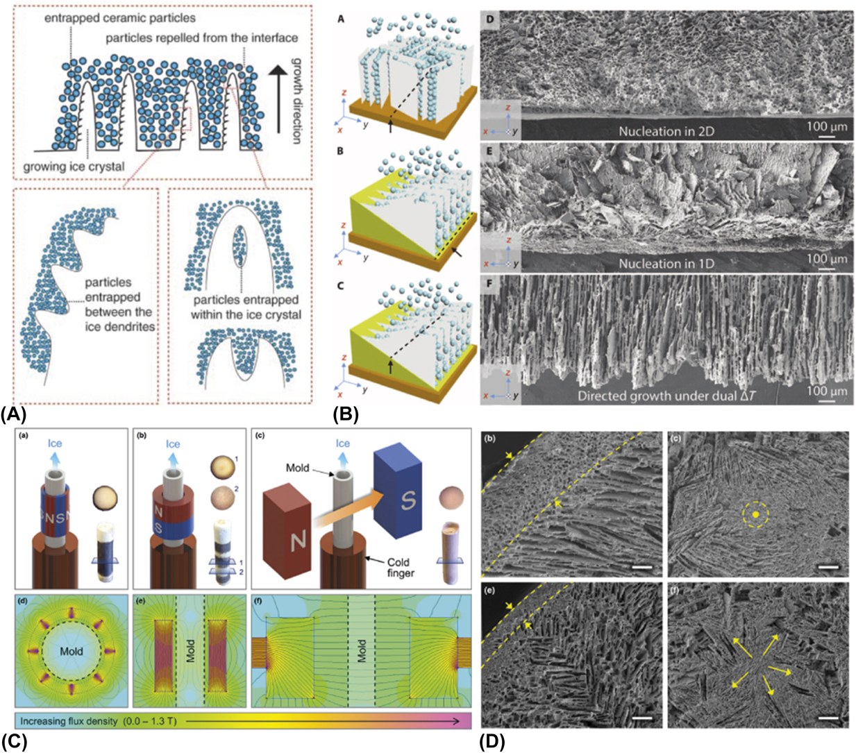
FIG. 8. External fields applied to freeze-casting. (A) Schematics of the principle of freeze-castingReference Deville, Saiz, Nalla and Tomsia95 (copyright © 2006 AAAS). (B) Schematics and electron micrographs of ordered ceramic materials under various temperature gradientsReference Bai, Chen, Delattre, Tomsia and Ritchie99 (copyright © 2015 AAAS). (C) Cartoons and finite element models of freeze casting with external magnetic fields in several designs and (D) the microstructures obtainedReference Porter, Niksiar and Mckittrick101 (copyright © 2016 John Wiley and Sons). Scale bars are 200 µm.
Slip-casting is a method that consists of pouring a particulate suspension onto a porous mold that concentrates the particles into a green body. This green body is then sintered to form a dense ceramic [Fig. 9(a)]. The porosity of the mold, through capillary forces, sucks in the liquid with a kinetic described by the equation
 $$x = \sqrt {{{2J\Delta P} \over {\eta R}}t} \quad ,$$
where x is the thickness of the deposited layer of the particle onto the mold, t is the time, J is the ratio between the volume of this layer and the extracted liquid, R is the hydrostatic resistance, ΔP is the difference in pressure across the deposit, and η is the viscosity of the liquid. Typically, this method is used to cast complex shaped objectsReference Mangels and Riley107 and can be accommodated to fabricate controllable composition gradients by gradually mixing two slurriesReference Marple and Boulanger106 [Fig. 9(b)]. Slip-casting can be coupled with rotating magnetic fields to generate complex orientations of anisotropic 2-D particles. Due to the well-defined kinetics of the fluid removal and of the deposit growth, temporal variation in magnetic field orientation transposes directly into spatial variation in particle orientation. Using this method, macroscopic assemblies with periodic arrangements of particles were fabricated and with layer thicknesses and orientations that could be predicted knowing the kinetics [Eq. (1)] and the time-variation of the magnetic fieldReference Le Ferrand, Bouville, Niebel and Studart105 [Fig. 9(c)]. These structures are layers of oriented particles with finite size and following the curves of the mold. The multilayering can thus be obtained in complex-shaped objects and in a single casting event, in opposition to the sequential layering by tape-casting. Using this method, a bilayer ceramic tooth was created, replicating the actual shape of a human molar and its internal microstructure and properties, in a ceramic composite containing a mineral concentration above 60%Reference Le Ferrand, Bouville, Niebel and Studart105 [Figs. 9(d)–9(f)].
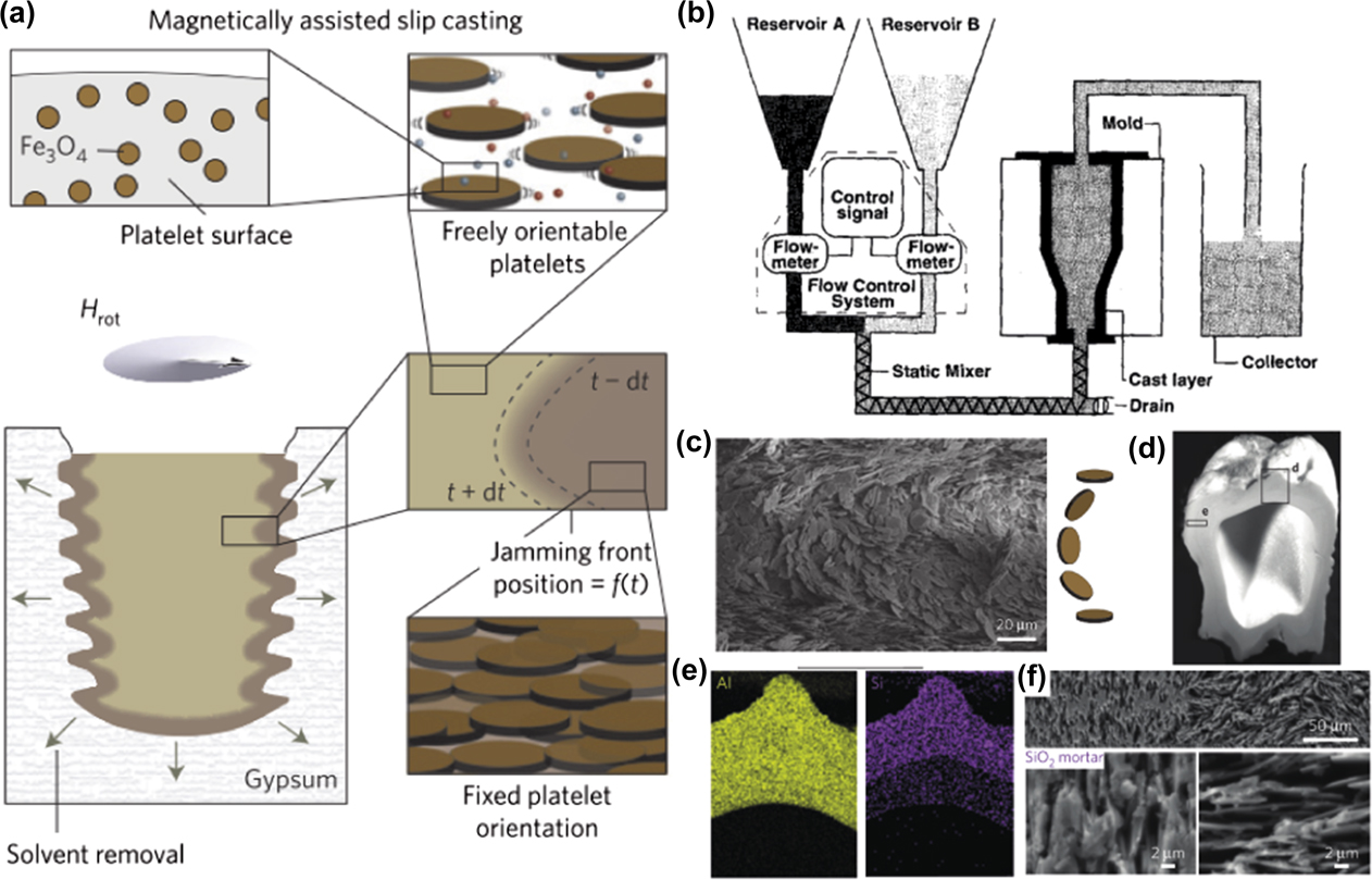
FIG. 9. External fields applied to slip-casting. (a) Schematics of the slip-casting with external magnetic field indicating the surface modification of the particles and the time-dependent growth of the deposited layer at the surface of the porous mold of gypsumReference Le Ferrand, Bouville, Niebel and Studart105 (copyright © 2015 Springer Nature). (b) Set-up used to create controlled composition gradients in slip-castingReference Marple and Boulanger106 (copyright © 1994 John Wiley and Sons). (c–f) Electron micrograph, optical image, X-ray elemental map, and micrographs, respectively, indicating the diversity in particle orientations, shape and chemical compositionReference Le Ferrand, Bouville, Niebel and Studart105 (copyright © 2015 Springer Nature). Scale bars: (c) 20 µm, (f) from top to bottom and right to left: 50 µm, 2 µm, 2 µm.
Recent advances in 3D printing technologies bring along exciting capabilities such as variations of composition, shape, local structural design, and local density as the material is printed (Fig. 10). 3D printing of composites is performed by several methods:
(i) Laser printing, where the printer head is used to locally cure the matrix in a bulk solution [Fig. 10(a)].
(ii) Stereolitography, where the material deposited is cured by UV before depositing another layer [Fig. 10(b)].
(iii) Direct-ink writing where the material is extruded through a nozzle and keeps its shape thanks to a shear-thinning ink formulation [Fig. 10(c)]. In this latter case, the object is first entirely printed in 3D, then can be cured for consolidation.
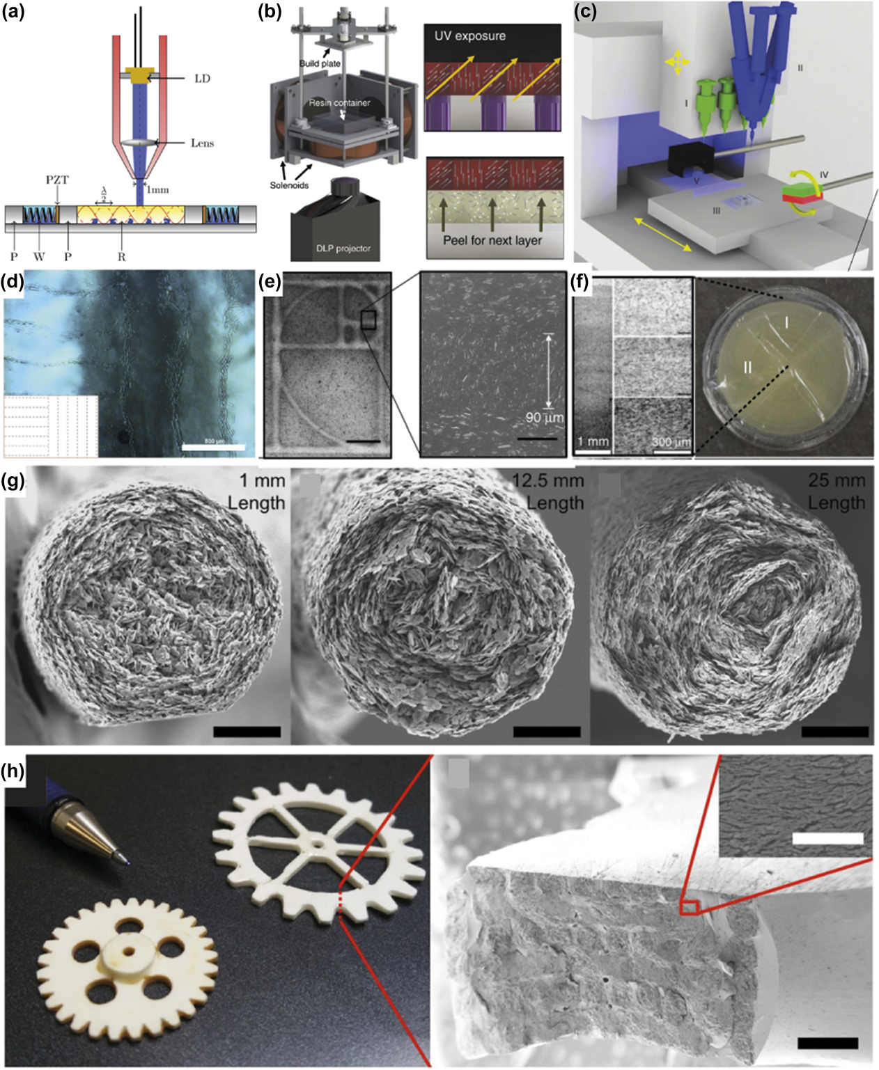
FIG. 10. External fields applied to 3D printing. (a) Schematics for laser printing in an acoustic fieldReference Llewellyn-Jones, Drinkwater and Trask108 (copyright © 2016 IOP Publishing), (b) stereolithography with magnetic fieldReference Mangels and Riley107 (copyright © 2015 Springer Nature) and (c) direct-writing with magnetic fieldReference Kokkinis, Schaffner and Studart88 (copyright © 2015 Springer Nature), and (d, e, and f) the optical micrographs of the structures obtained with these methods. Scale bars: (d) 100 µm, (e) 500 µm and 50 µm from left to right and (f) 1 mm and 300 µm. (g) Images of the cross sections of filaments printed using concentrated suspension of 2-D particles via direct-ink writing and (h) the macroscopic final objects and closer view on their microstructureReference Feilden, Ferraro, Zhang, García-Tuñón, D’Elia, Giuliani, Vandeperre and Saiz110 (copyright © 2017, Springer Nature).
3D printing techniques have been coupled with external fields to increase the degree of internal control of the materials deposited. Acoustic fields have been used in laser printing to create oriented arrays of glass fibers in multiple directionsReference Llewellyn-Jones, Drinkwater and Trask108 [Fig. 10(d)]. Magnetic alignment, due to its simplicity and compatibility with the printer, has been used to orient 1-D fibers in deposited filaments,Reference Martin, Riederer, Krebs and Erb63 and to biaxially orient 2-D particles in localized and controlled directions in spaceReference Kokkinis, Schaffner and Studart88,Reference Martin, Fiore and Erb109 [Figs. 10(e) and 10(f)]. Recent strategies rely on controlled shear at the nozzle. By rotating the tip of the nozzle during the extrusion, 1-D fibers can be oriented in ways non-trivially available by other means.Reference Raney, Compton, Mueller, Ober, Shea and Lewis111 The examples provided so far have however limited mineral content. Since the extrusion through the nozzle or the acoustic manipulation requires the suspensions to have shear-thinning behavior and to allow for UV-curing, the amount of particles has been limited to 10%. Nevertheless, one example of direct writing of a dense ceramic is shown in Figs. 10(g) and 10(h).Reference Feilden, Ferraro, Zhang, García-Tuñón, D’Elia, Giuliani, Vandeperre and Saiz110 The authors exploited the shear properties of a suspension of anisotropic alumina platelets in concentrations exceeding 30 vol%. They determined the geometry of the nozzle required to obtain random or concentric alignment patterns in the printed filaments. This control of the shear profile at the nozzle level allows for concentric alignment over controllable thicknesses. Using this method, dense assemblies with helicoidal patterns similar to that presented in Fig. 2(c), but at the filament level, could be realized.
VI. FLEXIBILITY, CONTROLLABILITY, AND SCALABILITY OF THE METHODS
The total degree of freedom (TDoF) of each of the techniques presented earlier is a relevant indicator to determine how much design freedom they allow for creating controlled and complex heterogeneous architectures (Fig. 11). The TDoF is the number of parameters that can be controlled independently, namely the possibility to:
(i) Orient particles uniaxially or biaxially.
(ii) Control their position.
(iii) Tune the density and the volume fraction of particles.
(iv) Control the chemical composition.
(v) Control of the shape.
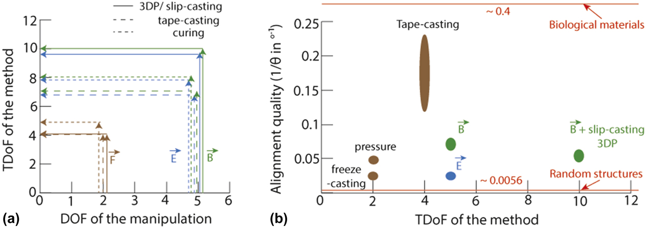
FIG. 11. Design space and alignment quality comparison. (a) TDoF of the method as a function of the DOF given by the external field. Continuous lines indicate additive manufacturing types of processes. (b) Alignment quality as a function of the TDoF of the method. Data from Ref. Reference Bouville, Maire and Deville85 for freeze-casting, Ref. Reference Bouville, Maire, Meille, van de Moortèle, Stevenson and Deville123 for pressure and Ref. Reference Behr, Vainio, Müller, Schreyer and Schneider72 for sedimentation, Ref. Reference Rozynek, Castberg, Mikkelsen and Fossum119 for electric field, Ref. Reference Bonderer, Studart and Gauckler120 for magnetic alignment, Refs. Reference Pavlacka and Messing89 and Reference Bonderer, Studart and Gauckler120 for tape-casting, Ref. Reference Le Ferrand, Bouville, Niebel and Studart105 for slip-casting with magnetic field, and Ref. Reference Kokkinis, Schaffner and Studart88 for 3D printing and magnetic field. Bone structure is used as an example of the biological material.Reference Wagermaier, Gourrier, Aichmayer, Fratzl, Dunlop and Weinkamer121
The TDoF is a simplified yet more complete parameter than the degree of freedom (DOF) defined in Fig. 6 and is described by the following equation:
 $${\rm{TDoF}} = {\delta _{\lg }} \cdot {\Delta _{{\rm{local}}}} \cdot {\rm{DOF}} + \left( {1 - {\delta _{\lg }}} \right) \cdot \left( {{\Delta _{{\rm{global}}}} + {\rm{DOF}}} \right)\quad ,$$
where Δlocal and Δglobal are the numbers of parameters from the slurry that vary locally and globally, respectively, and DOF is the degree of freedom from the manipulation of and δlg a factor such as δlg = 0 if the method does not allow for local variations and δlg = 1 if it does. Therefore, considering curing, δlg = 0 and TDoF = Δglobal + DOF. The parameters that can be tuned are the density, composition, and shape; therefore TDoF = 3 + DOF. In the case of tape-casting, the overall shape cannot be varied, so TDoF = 2 + DOF. For slip-casting and 3D printing, two additive manufacturing methods, δlg = 1 and TDoF = Δlocal·DOF. The local parameters that can be varied are density and composition and therefore TDoF = 2 × DOF. Shape is not a variable and is an inherent consequence from the capability for local variations. Figure 11(a) summarizes the TDoF attainable for these methods. As a result of the bottom–up assembly principle offered by additive manufacturing, the TDoF of electromagnetic manipulation of particles combined with these techniques is at its maximum for slip-casting and 3D printing methods.
Furthermore, to estimate the suitability of a technology for precise fabrication of controlled structures, it is important to characterize the alignment quality achieved. Optical observations of the reflection of light or of the appearance of birefringent colors are qualitative means to determine particle orientation at the surface of a bulk sample. Typically, for large micrometric particles, light reflection at the edges will lead to less intensity of light reflection and therefore a darker color will be observed in comparison to the plane of the large surface area of the particles.Reference Le Ferrand, Bouville and Studart93,Reference Le Ferrand, Bouville, Niebel and Studart105 In addition, if one dimension of the particles or the interparticle spacing lies within the spectral range of light, structural colors or birefringence may emerge, indicating nematic, smectic, or chiral arrangements. This phenomenon is observed, for example, in concentrated clay suspensions.Reference Michot, Bihannic, Maddi, Funari, Baravian, Levitz and Davidson112 Quantitative information can be obtained by X-ray methods such as rocking curves,Reference Vaudin113 small angle X-ray scattering (SAXS),Reference Liebi, Georgiadis, Menzel, Schneider, Kohlbrecher, Bunk and Guizar-Sicairos114 and image analysis.Reference Kokkinis, Schaffner and Studart88 In these methods, the quality of the alignment is measured as the inverse of the angle distribution of the particles. The full width at half maximum of the angle distribution is directly available with the rocking curvesReference Libanori, Erb and Studart44 or by plotting the intensity as a function of the azimuthal angle from SAXS diffraction patterns.Reference De Silva, Petermann, Kasmi, Impéror-Clerc, Davidson, Pansu, Meneau, Perez, Paineau, Bihannic, Michot and Baravian115 In addition, an order parameter S can be extracted from the angle distribution using the following equations:
 $$S = {{\int_{\theta = 0}^{2\pi } {I\left( \theta \right)M\left( \theta \right){\rm{d}}\theta } } \over {\int_{\theta = 0}^{2\pi } {I\left( \theta \right){\rm{d}}\theta } }}\quad ,$$
where I(θ) is the scattered intensity at the angle θ and M is the Legendre polynomial, or a simplified equationReference Qazi, Rennie, Wright and Cockcroft116,Reference Greasty, Richardson, Klein, Cherns, Thomas, Pizzey, Terrill and Rochas118 :
 $$S = {1 \over 2}\left( {{{\cos }^2}\theta - 1} \right)\quad .$$
Performing X-ray measurements in SAXS, in particular, is interesting to access bulk information without the need for cutting and polishing samples that might cause local defects and misorientation. To obtain localized information about the microstructure and the composition in complex heterogeneous structures, 3D small- and wide-angle scattering from synchrotron sources, allied with tomographic reconstruction, have been applied to successfully reconstruct in 3D, the local microstructure of trabecular bone.Reference Liebi, Georgiadis, Menzel, Schneider, Kohlbrecher, Bunk and Guizar-Sicairos114,Reference Schaff, Bech, Zaslansky, Jud, Liebi, Guizar-Sicairos and Pfeiffer117 These methods are suitable for heterogeneous dense composite architectures since unconventional alignment is hard to decipher in cut slices. Using slices, measurement at several cutting angles would be required to retrieve local orientations of 2-D particles in 3-D. Finally, in situ set-ups using electric fieldReference Greasty, Richardson, Klein, Cherns, Thomas, Pizzey, Terrill and Rochas118 or shear-induced manipulation of particles during the measurements can be performed using synchrotron X-rays to give a direct correlation between the forces and torques applied and the alignment obtained.Reference De Silva, Petermann, Kasmi, Impéror-Clerc, Davidson, Pansu, Meneau, Perez, Paineau, Bihannic, Michot and Baravian115,Reference Qazi, Rennie, Wright and Cockcroft116
Figure 11(b) is a visual summary of the capacity of the fabrication methods to reach high design flexibility with high alignment quality. The first observation is that all methods reach an alignment quality within 0.025–0.1. For comparison, a natural structure with aligned crystals and characterized with these techniques gives a misalignment of ∼2.5° and therefore an alignment quality of 0.4.Reference Wagermaier, Gourrier, Aichmayer, Fratzl, Dunlop and Weinkamer121 On the other side, a totally random structure would have a misorientation of 180° and an alignment quality of 0.0056. The highest alignment quality is obtained for tape-casted processes, while freeze-casting and electric fields have the lowest. Magnetic fields nevertheless present the advantage of being easily combined with all the processes, in particular with additive manufacturing, and therefore can couple high TDoF with good alignment. However, the effect of alignment on the properties is not clear. For example, in nacre-like structures with biaxially aligned arrangements, theoretical models and simulations seem to indicate that a perfect alignment is required to enable periodicity and damping of mechanical waves for extreme mechanics.Reference Nemat-Nasser, Sadeghi, Amirkhizi and Srivastava122 Experimentally, dense nacre-like alumina-silica ceramics prepared by freeze-casting and pressing exhibit a toughness  ${K_{{\rm{JC}}}}\; \sim \;12\;{\rm{MPa}}\sqrt m$ after a crack length of Δa = 0.2 mm.Reference Bouville, Maire, Meille, van de Moortèle, Stevenson and Deville123 Same ceramics composition prepared using slip-casting and magnetic alignment, hence lower degree of misalignment, exhibit a toughness of ${K_{{\rm{JC}}}}\;\sim\;14\;{\rm{MPa}}\sqrt m$ after the same crack length.Reference Le Ferrand, Bouville, Niebel and Studart105 However, the crack extension is doubled in the case with lower alignment. The influence of alignment therefore should be considered carefully, taking into account other factors. The interfacial strength, in particular, is an important variable that affects the mechanics of aligned structures depending on the angle between the incoming crack and the deflecting interface.Reference Mirkhalaf, Dastjerdi and Barthelat124
Up-scaling in fabrication time and in the size of the parts and the programmability of the local hierarchical architecture are important for the potential transfer of these technologies to industrial processes and for the fabrication of customized parts specially adapted for their application. Multilayering easily allows customization, and the use of external fields in each layer could be automated, but is time consuming due to the lag time between the deposition and consolidation of each layer. Furthermore, the thickness of each layer obtained typically is of a few millimeters at most. Thus, the number of layers to stack for the fabrication of a macroscopic part of 1–10 cm in thickness is on the order of 10–1000.Reference Pavlacka, Bermejo, Chang, Green and Messing94 One additional major constrain is the lack of shaping flexibility: the method inevitably leads to sheet-like pieces. Freeze-casting, on the other hand, is a method that has caught a lot of attention by the well-established descriptions of its principlesReference Deville, Saiz, Nalla and Tomsia95 and the facility of the set-up for bulk pieces. The theoretical description of the method can be used effectively to program the final architecture as described in Sec. IV. Freeze-casting is a bulk method yielding macroscopic samples typically of 2–3 centimeters in thickness with no theoretical limitations on the lateral dimensions. Scale-up in size would simply result from scaling up the set-up. To the best of my knowledge, no study has yet tackled shaping of complex parts using this technology but no stringent restrictions are foreseeable. Control and localization of the microstructure have been implemented by the use of additional external fields. Compositional gradients have been scarcely explored using extrusionReference Ahn, Moon, Maeng, Koh and Kim125 and could also possibly be implemented using similar set-ups as for slip-casting [Fig. 9(b)]. Slip-casting is similarly scalable in shape and time, with the additional advantage of being originally an industrial process. Supplemented by external fields, the orientation of the particles, their localization, and their composition can be modified both globally or locally in complex shapes.Reference Le Ferrand, Bouville, Niebel and Studart105 Finally, 3D printing based on extrusion technologies with external fields offers local control in composition and orientation, a large variability in shape and the possibility of hierarchically structuring porous objects. 3D printing is also programmable by essence and can be scaled-up in time and dimensions. Programming and automation of the printing are controlled by computer aided design software that can also control the external fields. Another specificity of 3D printing that is not easily available in other methods is the possibility to change the design as the material is processed. This property could be useful in cases where the evolution of the materials with time is important.
Slip-casting and extrusion-based 3D printing supplemented with external fields are additive manufacturing techniques. Their bottom-up fabrication principle mimicks the bottom–up synthesis of most natural materials by living cells and consequently offers extensive design flexibility. These methods therefore have huge potential in designing complex heterogeneous and microstructured dense composites.
Furthermore, sample pieces as large as 10 cm diameter and 1 cm in thickness could be produced reliably in the laboratory.Reference Le Ferrand, Bouville, Niebel and Studart105 This is promising for larger pieces. However, theoretical scalability will demand further optimization to maintain reproducible and reliable results.Reference Mirkhalaf, Dastjerdi and Barthelat124 Indeed, antifoaming agents might be required during the slurry preparation and the mixing and deagglomeration of the powders. The slurry should also demonstrate long time colloidal stability. For good handling and storing characteristics, large green body might demand addition of organic binders. Finally, shape retention after solvent removal should not be affected by the microstructure and composition variation within the sample. Indeed, microstructuring has been found to shape ceramics into spectacular coil structures in bilayers of 200 µm thickness.Reference Bargardi, Le Ferrand, Libanori and Studart90 However, reducing the layer thickness and producing larger construct could maintain a homogeneous drying.Reference Le Ferrand, Bouville and Studart127
VII. PROPERTIES OF HIGHLY MINERALIZED COMPOSITES WITH BIO-INSPIRED MICROSTRUCTURES
The properties achieved by hierarchically structuring highly mineralized composites are diverse and can surpass those of the natural material they are inspired from, but further optimization and understanding are still required to implement natural strategies into synthetic dense composites (Fig. 12).

FIG. 12. Examples of properties of architectured highly mineralized composites. (A) Maximum mechanical toughness achieved for natural nacre and bio-inspired nacre-like composites composed of Al2O3-PMMA (polymethymethacrylate),Reference Munch, Launey, Alsem, Saiz, Tomsia and Ritchie128 Al2O3–Cu,Reference Le Ferrand, Bouville, Niebel and Studart105 Al2O3–Ni,Reference Xu, Huang, Zhang, Daryadel, Behroozfar, Mcwilliams, Boesl, Agarwal and Minary-Jolandan129 and Al2O3–SiO2Reference Le Ferrand, Bouville, Niebel and Studart105,Reference Bouville, Maire, Meille, van de Moortèle, Stevenson and Deville123 to highlight the range of mechanical properties attainable and the multifunctionalities of the resulting materials. (B) Schematics of the mode of fracture imposed onto a hierarchical dense alumina composite produced by direct writing in dense concentrations of particles and the corresponding toughnessReference Feilden, Ferraro, Zhang, García-Tuñón, D’Elia, Giuliani, Vandeperre and Saiz110 (copyright © 2017 Springer Nature). (C) The electron and optical micrographs highlight the crack deflection occurring in the microstructured specimen.Reference Feilden, Ferraro, Zhang, García-Tuñón, D’Elia, Giuliani, Vandeperre and Saiz110 Scale bars: (a, b, and c) 300 µm, (d) 29 µm, (e) 10 µm, and (f) 0.5 mm (copyright © 2017 Springer Nature). (D) Schematics of energy dissipation mechanisms found in natural highly mineralized composites, in particular, seashells.Reference Wegst, Bai, Saiz, Tomsia and Ritchie2 (copyright © 2014 Springer Nature) (E) Electron micrographs of polished cross section of highly mineralized composites with 60 vol% of alumina particles and with tunable interparticle roughness. The roughness is controlled by titanium oxide nanoclusters that form at the surface of the particles as the temperature increasesReference Grossman, Bouville, Erni, Masania, Libanori and Studart130 (copyright © 2017 John Wiley and sons).
First, by reproducing biological structural elements in chemical systems close to the natural example, similar and enhanced properties could be obtained [Fig. 12(A)]. The nacre brick-and-mortar structure has been the source of numerous studies and provides excellent examples that will be discussed in the following. Using mineralization of ions to form calcium carbonate onto a porous organic template, subsequently followed by infiltration and mechanical pressure, Mao et al. produced artificial nacre structures with mechanical properties close to that of natural nacre.Reference Mao, Gao, Yao, Liu, Cölfen, Liu, Chen, Li, Yan, Liu and Yu131 The specimens combine specific strengths and toughness, a rising resistance to crack propagation due to crack deflection and interlamellar debonding at the interface between the mineral tablets.Reference Mao, Gao, Yao, Liu, Cölfen, Liu, Chen, Li, Yan, Liu and Yu131 This artificial nacre is augmented with structural iridescence colors. Using gravitational field and evaporation-induced self-assembly, Gao et al. reproduced nacre structure from preformed calcium-based platelets in a faster and scalable manner.Reference Gao, Chen, Mao, Song, Bin Yao, Cölfen, Luo, Zhang, Pan, Meng, Ni and Yu132 Mechanical properties are similar to that of the natural material and also feature multiple crack deflection, crack bridging, platelet pull-out, dissipation mechanisms that are responsible for the rising energy needed to propagate the crack throughout the structure.Reference Gao, Chen, Mao, Song, Bin Yao, Cölfen, Luo, Zhang, Pan, Meng, Ni and Yu132
Second, benefiting from the use of synthetic building blocks with superior performance than the natural ones, mechanical properties of bio-inspired and dense assemblies that largely surpass the natural ones can be constructed. This is the key advantage of synthetic means over natural fabrication, in addition to scaling and speed. Beyond purely mimicking biomaterials, bio-inspiration aims at applying the strategy found in nature to other constituents to enhance their properties. As such, researchers have been extensively using alumina microplatelets, available in bulk quantities, as the primary building block for nacre-like composites. Despite a very high mechanical strength, alumina remains a ceramic and therefore breaks catastrophically. The nacre-like structure applied to alumina is a strategy to obtain a temperature and chemically resistant material that also has high strength and toughness. Using freeze-casting or slip-casting with magnetic alignment and hot pressing, nacre-like alumina with toughness 6 times higher than the natural seashell was obtained.Reference Le Ferrand, Bouville, Niebel and Studart105,Reference Bouville, Maire, Meille, van de Moortèle, Stevenson and Deville123,Reference Munch, Launey, Alsem, Saiz, Tomsia and Ritchie128 Synthetic processes also allow for further modification to generate multiple functions. Electrical conductivity, for example, can be harnessed via the incorporation of metallic particles. During hot pressing, the metallic particles locally melt and form a percolating network throughout the composite giving electrical conductivity, in addition, the mechanical strength and toughness.Reference Le Ferrand, Bouville, Niebel and Studart105 Other examples include the use of piezoelectric filler polymers for piezoelectric, high strength, and transparent ceramic composites,Reference Gao, Chen, Mao, Song, Bin Yao, Cölfen, Luo, Zhang, Pan, Meng, Ni and Yu132 or anisotropic swelling and shrinking upon immersion in a solvent or during high temperature sintering.Reference Erb, Sander, Grisch and Studart87,Reference Kokkinis, Schaffner and Studart88,Reference Bargardi, Le Ferrand, Libanori and Studart90
However, the higher the mineral content, the more challenging the processes. The method developed, involving high temperature or pressure, further deviate from biological processes. Then, the properties of the materials fabricated do not present the extraordinary properties found in the natural ones. For example, helicoidal arrangements and heterogeneous architectures in fully dense alumina composites do present improvement in their mechanical toughness but not at the extent found in natural materials. One probable reason for this is that the interfacial properties between the grains are too strong and stiff to promote the large panel of energy dissipation mechanisms found in natural composites [Figs. 12(B) and 12(D)]. To address this issue, efforts are being made to control the properties at the interface between the building blocks to allow for more stress transfer, interlocking, and friction.Reference Wegst, Bai, Saiz, Tomsia and Ritchie2,Reference Dastjerdi, Rabiei and Barthelat24,Reference Grossman, Bouville, Erni, Masania, Libanori and Studart130 By exploiting the coalescence and cluster formation of titanium oxide at the surface of alumina platelets under high temperature treatment, the toughness of dense alumina nacre-like composites could be increased simply by tuning and optimizing the interfacial roughness [Fig. 12(E)].Reference Grossman, Bouville, Erni, Masania, Libanori and Studart130 Another factor preventing the direct comparison of artificial and natural composites is that despite progress in microstructuring, the materials achieved are still far from the complexity observed in natural materials where microstructure spans over multiple length scales.Reference Wegst, Bai, Saiz, Tomsia and Ritchie2–Reference Dunlop and Fratzl4
VIII. CONCLUSION
The current pathways for obtaining highly mineralized composites and ceramics have been reviewed and discussed to identify the stages where the application of external fields can be used to hierarchically structure synthetic materials. The theory of manipulation of particles using external fields and their set-ups have been described as well as how this manipulation can take place in concentrated suspensions. The current state-of-the art methods for obtaining highly mineralized composites with complex heterogeneous microstructures have been explored and their strengths and limitations have been evaluated. Finally, the benefit of fabricating these structures in highly mineralized composites in terms of their material properties have been highlighted.
To conclude, employing external fields to produce these high value materials might appear to come at a great fabrication cost. But it could be expected that the value added in terms of life-time, customization, and adaptability of the processes can surpasses this detrimental cost. The use of additive manufacturing and specifically advanced manufacturing is a good strategy to reduce material waste and employing bio-inspired designs brings extra properties from only poor materials.
There is currently immense research in the domain of bio-mimetics and bio-inspiration that focus on the transposition of these principles to the industrial scale.Reference Leo, Tallon, Stone and Franks126,Reference Lepora, Verschure and Prescott133,Reference Wanieck, Fayemi, Maranzana, Zollfrank and Jacobs134 The considerations to apply these concepts and these new materials go beyond the pure performance and take into account the public perception and need, the relevance of the product, and the sustainability of the manufacturing process from the fabrication of the materials’ constituents to the end of life of the parts. In parallel to industrial goals, the great progress that has been made to produce these intricate materials is also a unique tool to better understand the mechanisms that make natural materials diverse and at the same time unique. By varying the parameters, the orientations, the shape of the particles, the chemistry, etc., using experimental assessment and computer simulations, it is possible to explore, for example, the influence of the organic matrix in these highly mineralized composites,Reference Niebel, Bouville, Kokkinis and Studart135 of nacre-like mineral bridges on crack propagation.Reference Grossman, Bouville, Erni, Masania, Libanori and Studart130 The materials fabricated will thus allow to further explore current models, for example, related to wave propagation and the existence of band gaps in natural multilayered materials.Reference Yin, Huang, Zhang, Zhang and Chen136
Finally, additive manufacturing technologies enable the design of on-demand local properties within a material. Alike in nature where the environmental constraints influence the structure of the biocomposites, synthetic applications require specific architectures. For instance, localized designs using external fields and high mineralization can be used to locally reinforce a hole in a soft matrix.Reference Erb, Libanori, Rothfuchs and Studart62,Reference Kokkinis, Bouville and Studart137 Fabrication of unconventional shapes to produce patient-adapted teeth or wear-resistant textile threads is also feasible by additive manufacturing aided with external fields that aim highly mineralized bioinspired structures.Reference Bargardi, Le Ferrand, Libanori and Studart90,Reference Le Ferrand, Bouville, Niebel and Studart105
IX. NOMENCLATURE

ACKNOWLEDGMENTS
The author acknowledges Ahmet Demirors for revising the manuscript and providing valuable inputs, and funding from Swiss National Science Foundation (grant_P2EZP2_172169).


 Open access