

I. INTRODUCTION
Nanoporous metals (NPMs) containing a network of nanoscale pores provide an attractive combination of physical and mechanical properties afforded to them by their nanostructures. Offering low density, high specific (i.e., density-normalized) surface area, and high specific strength while retaining many characteristics of bulk metals, this burgeoning class of metallic materials has garnered considerable research interest. Reference Vukovic, ten Brinke and Loos1–Reference Tappan, Steiner and Luther6 In addition to use as lightweight materials, nanoporous metals also have potential applications in a diverse array of technologies, such as optical metamaterial, Reference Vignolini, Yufa, Cunha, Guldin, Rushkin, Stefik, Hur, Wiesner, Baumberg and Steiner7 catalysis, Reference Kou, Li, Zhang, Zhang and Yang8,Reference Wittstock, Zielasek, Biener, Friend and Bäumer9 energy storage, Reference Liu, Gillette, Chen, Pearse, Kozen, Schroeder, Gregorczyk, Lee and Rubloff10 gas storage and filtration, Reference Morris and Wheatley11 electromagnetic sensing, Reference Zhang and Li12 and high-coercivity magnets. Reference Hsueh, Huang, Ho, Lai, Makida and Hasegawa2 With the continued realization of their unique properties, nanoporous metals are positioned to drastically invigorate the applicability of metals in new high-performance applications. However, challenges in synthesis of nanoporous metallic materials continue to limit the extent to which they are understood.
The synthesis of highly ordered, nanostructured porous metallic materials represents an important area of contemporary exploration. While methods for the fabrication of nanoporous metals have proliferated over the last two decades, many yield metals with inhomogeneous pore dimensions and are not generalizable to a large majority of metallic species. Table I summarizes several common methods for fabricating porous metals and details their corresponding pore characteristics. While additional methods exist for the creation of nanoporous oxides, the prime focus of this review is to detail the fabrication of elemental metallic nanofoams.
TABLE I. A survey of methods that are commonly used for fabricating nanoporous metals.

A common method for the creation of nanoporous metals is dealloying. An active metallic species is selectively leached (chemically or electrochemically) from a binary alloy. Reference Erlebacher, Aziz, Karma, Dimitrov and Sieradzki13,Reference Erlebacher and Sieradzki14 Dealloying produces pores of nanoscale dimensions in an assortment of metals with varying complexity in the pore size distribution. Alloys that have complete solubility across all compositions often yield nanoporous metals with unimodal pore size distributions. For example, nanoporous Au with fairly uniform pore sizes (5–200 nm) has been produced via dealloying of the globally miscible Au–Ag solid solution. Reference Seker, Reed and Begley3,Reference Qiu, Peng, Li, Xu and Wang5,Reference Liu, Bliznakov and Dimitrov15 The presence of intermetallic compounds in alloy systems often produces nonunimodal pore size distributions upon dealloying. For example, dealloying of Au–Al alloys containing an Al2Au phase and a pure Al phase removes Al from both phases, leading to a bimodal nanopore size distribution. Reference Zhang, Wang, Qi, Lin and Bian16 As the number of intermetallic phases increases, so does the potential for complexity in the pore morphology of the resultant porous metal. Dealloying of rapidly solidified Al70Pd30 comprised of Al3Pd and Al3Pd2 phases has led to a tortuous nanoporous Pd structure (3–25 nm) in the regions of native Al3Pd, while the native Al3Pd2 regions demonstrated immunity to dealloying and remained intact, yielding a “composite” of nanoporous and solid metal regions. Reference Wang, Wang, Qi, Zhao, Ji and Zhang17 With the adjustment of electrochemical parameters in dealloying processes and introduction of subsequent annealing, pore sizes can be tuned. Reference Seker, Reed and Begley3,Reference Qiu, Peng, Li, Xu and Wang5,Reference Liu, Bliznakov and Dimitrov15,Reference Wang, Wang, Qi, Zhao, Ji and Zhang17,Reference Detsi, Selles, Onck and De Hosson18 Dealloying for the creation of nanoporous metals is largely limited in scope to favor precious noble metals. However, Rahman et al. recently demonstrated the applicability of an analogous electrochemical dealloying technique to the Ni–Al system (Ni30Al70) to produce nanoporous nickel; the distribution of pore sizes was wider than that of traditional Au–Ag systems, and the process was highly sensitive to the composition of the parent alloy. Reference Rahman, Zhu and Wen19 Similarly, nanoporous Cu has been synthesized via dealloying from a Cu–Al alloy. Reference Xing, Wang, Fang, Zhang and Liu20 In recent years, dealloying using a liquid metal instead of an aqueous solution has been developed to produce nanocomposites as well as nanoporous metals. Reference Geslin, McCue, Gaskey, Erlebacher and Karma21 For example, an Nb–Ni alloy was immersed in molten Mg where Ni atoms were dealloyed (i.e., dissolved in Mg), and removal of the Mg–Ni phase by immersing the composite in nitric acid leads to a porous Nb structure. Reference Kim, Tsuda, Wada, Yubuta, Kim and Kato22 Porous Ti, Reference Chen-Wiegart, Wada, Butakov, Xiao, De Carlo, Kato, Wang, Dunand and Maire23 Fe, and Fe–Cr Reference Wada and Kato24 have also been produced by a similar method.
Metallic foams have also been synthesized via controlled combustion of transition-metal complexes containing energetic ligands. Reference Tappan, Huynh, Hiskey, Chavez, Luther, Mang and Son4,Reference Tappan, Steiner and Luther6 Porous iron monoliths exceeding an inch in length with extremely high surface area density have been prepared by the combustion reaction method. The mean pore size and pore size distribution can be tuned by modulating the ambient pressure during combustion; for example, combustion at 2.07 MPa leads to the coexistence of large pores in the 1–3 μm regime and small pores in 20–200 nm range, while increasing the pressure to 7.33 MPa results in predominantly 20–200 nm pores. Reference Tappan, Huynh, Hiskey, Chavez, Luther, Mang and Son4 Porous Co, Cu, and Ag with similar pore morphology have also been produced using this method. Reference Tappan, Steiner and Luther6 In addition, electrodeposition of copper in a CuSO4–H2SO4 solution with nonsuppressed hydrogen evolution was demonstrated to facilitate porous metal formation with dendritic ligands; the resultant pores were predominantly 25–50 μm in size, and the walls consist of loosely assembled short struts with sizes as small as 50 nm. Reference Shin and Liu25,Reference Shin, Dong and Liu26
Thermomechanical processing has also proven successful in the fabrication of porous metals and is widely applicable. Reference Dunand27,Reference Scott and Dunand28 The simplest variety involves sintering of metal powders at elevated temperatures. Reference Dunand27 However, this method typically yields micrometer size pores that are largely a function of powder refining capability. Typical micron-scale spherical powders were shown to generate cusped pore shapes. Reference Dunand27 In the case of aluminum, uniaxial pressing during sintering accelerated the densification process and adjusted the final structure porosity (5–35%). Reference Dunand27 In some cases, space-holder particles are used during sintering which can later be selectively removed through melting (e.g., PMMA polymer Reference Köhl, Habijan, Bram, Buchkremer, Stöver and Köller29 ), dissolution (e.g., saccharose Reference Köhl, Habijan, Bram, Buchkremer, Stöver and Köller29 ), or evaporation processes (e.g., NaCl salt crystals, Reference Scott and Dunand28 Mg powder in Al Reference Dunand27 ). This approach is widely used in various elemental metal and alloy systems to improve controllability of the final pore structure and the size distribution. Reference Niu, Bai, Qiu and Wang30
The pore size d and sample dimension D of nanoporous metals from various fabrication methods reported in representative works are compiled in Fig. 1. NPMs from dealloying mostly have average d ranging from 3 nm to about 1 µm and D between 1 µm and 1 mm. Aside from dealloying, the aforementioned experimental procedures have mostly proven successful only in the synthesis of mesoporous metals with a wide pore size distribution involving large pore sizes (e.g., above 0.4 µm) (but with millimeter to centimeter sized samples), underlining the inherent challenge of assembly and stability in the fabrication of nanoporous metals with homogeneously-sized nanopores. Contrastingly, uniform nanoscale porosity in metals can be reliably achieved using templating methods involving deposition of metals onto a porous, sacrificial template that is subsequently removed. As shown in Fig. 1, porous templates can achieve uniform pore sizes as small as sub-nanometer to a few dozens of nanometers.
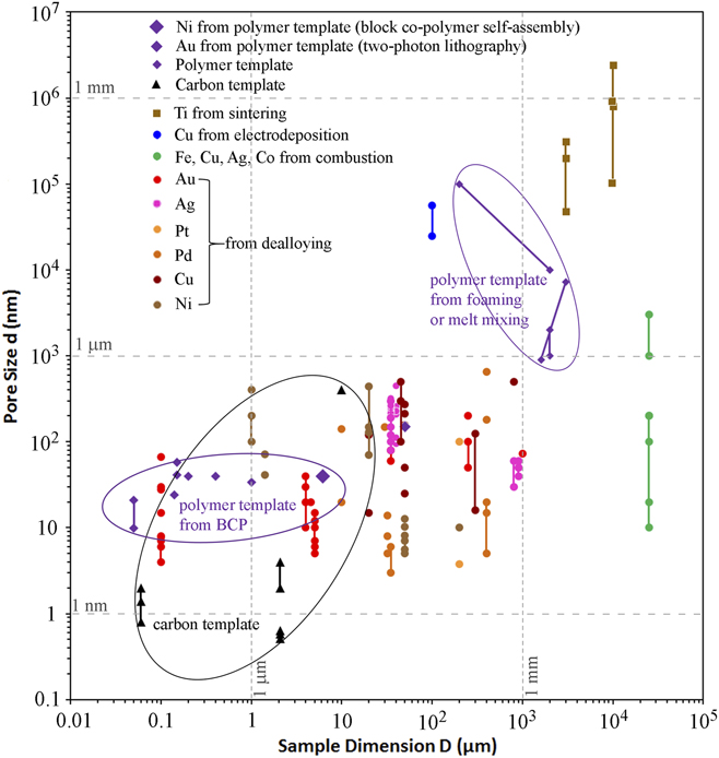
FIG. 1. Sample dimensions and pore sizes of nanoporous metals (or templates) fabricated by various methods, including Ni from polymer templates prepared by BCP self-assembly, Reference Hsueh, Huang, Ho, Lai, Makida and Hasegawa2,Reference Hsueh, Chen, She, Chen, Ho, Gwo, Hasegawa and Thomas68 Au lattice from polymer templates prepared by two-photon lithography, Reference Montemayor, Meza and Greer37 Ti from powder sintering, Reference Bram, Stiller, Buchkremer, Stöver and Baur69,Reference Thieme, Wieters, Bergner, Scharnweber, Worch, Ndop, Kim and Grill70 Cu from electrodeposition, Reference Shin and Liu25,Reference Shin, Dong and Liu26 Fe, Cu, Ag, Co from combustion, Reference Tappan, Huynh, Hiskey, Chavez, Luther, Mang and Son4 Au, Reference Seker, Reed and Begley3,Reference Liu, Bliznakov and Dimitrov15,Reference Zhang, Wang, Qi, Lin and Bian16,Reference Ji and Searson71–Reference Zhang, Wang, Qi, Zhang, Qin and Frenzel80 Ag, Reference Detsi, Selles, Onck and De Hosson18,Reference Zhang, Wang, Qi, Zhang, Qin and Frenzel80–Reference Zhang, Sun, Xu, Wang, Ji, Zhao and Zhang84 Pt, Reference Zhang, Wang, Qi, Zhang, Qin and Frenzel80,Reference Pugh, Dursun and Corcoran85 Pd, Reference Wang, Wang, Qi, Zhao, Ji and Zhang17,Reference Zhang, Wang, Qi, Zhang, Qin and Frenzel80,Reference Dan, Qin, Wada, Yamaura, Xie, Sugawara, Muto, Makino and Hara86–Reference Li, Ma, Huang and Ding89 Cu, Reference Xing, Wang, Fang, Zhang and Liu20,Reference Chen, Yu, Fujita and Chen90–Reference Zhao, Qi, Wang and Zhang94 and Ni Reference Rahman, Zhu and Wen19,Reference Dan, Qin, Sugawara, Muto and Hara95–Reference Sun, Chien and Searson98 from dealloying, as well as carbon template, Reference Gogotsi, Nikitin, Ye, Zhou, Fischer, Yi, Foley and Barsoum31,Reference Zhao, Su, Yan, Guo, Bao, Lv and Zhou33,Reference Gordeev, Kukushkin, Osipov and Pavlov99 and polymer templates fabricated by foaming, Reference Pavia, La Carrubba, Piccarolo and Brucato45 melt mixing, Reference Sarazin and Favis44 and BCP self-assembly. Reference She, Lo and Ho38,Reference Ho, Chiang, Chen, Wang, Hasegawa, Akasaka, Thomas, Burger and Hsiao42,Reference Ho, Tseng, Fan, Chiang, Lin, Ko and Huang47–Reference Liang, Hong, Guiochon, Mays and Dai49,Reference Hsueh, Chen, She, Chen, Ho, Gwo, Hasegawa and Thomas68 Lines in the figure represent a range of pore sizes or sample sizes.
The main goal of this article is to provide a review of contemporary templating methods used to fabricate nanoporous metals with uniform pore sizes, with a particular focus on polymer template-based methods. A general description of templating methods will be provided in Sec. II. In Sec. III, we will discuss the fabrication of nanoporous polymeric templates, which have empirically demonstrated functionality in nanoporous metal fabrication. Deposition of metals onto polymer templates will be discussed in Sec. IV and removal of templates in Sec. V. Critical fabrication process discoveries and limitations will be noted.
II. TEMPLATE-BASED FABRICATION OF NANOPOROUS METALS
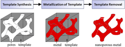
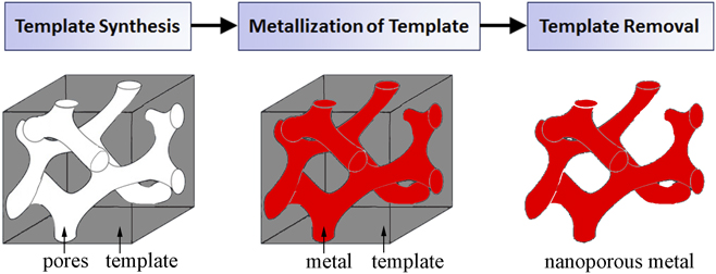
Templates act as a support scaffold for metallization procedures in the fabrication of porous metals, enabling a robust processing approach which addresses fundamental difficulties in nanoporous metal assembly and stability. By utilizing the nanoscale architectures more readily present in other material systems, metals in nontraditional nanoporous forms can be synthesized with a high degree of pore uniformity and organization. Template-based nanoporous metal fabrication methods generally involve three processing steps (template synthesis, metallization of template, and template removal), outlined in the process flow chart in Fig. 2. As the nanostructural form of the final nanoporous metal is largely determined by the pore dimensions and morphology of the template, template synthesis plays a pivotal role in the process. Physical vapor deposition and electrochemical/chemical plating techniques are potential methods for template metallization. There are two essential processing requirements for metallization. First, the process must yield sufficient metallic penetration into the template pores so as to create a continuous metallic network. Metallization also requires that the deposited metal be structurally supportive of its own mass for stability after eventual template removal; this requirement is related to template geometry. Sacrificial removal of the template ultimately yields a porous metal with a newfound structure representing the negative of the template. Template removal procedures vary between template species.

FIG. 2. A general process flow for template-based synthesis of nanoporous metals.
A. Hard templates
Templating processes for material assembly are traditionally classified according to the properties of the template. Hard templating methods make use of inorganic templates such as porous carbon materials. Carbide-derived carbon materials can contain uniform nanopores with sizes as small as 0.65–2.1 nm, and Fig. 3(a) shows one such material derived from Ti3SiC2 (chlorination in pure chlorine leads to Ti and Si extraction and carbon formation). Reference Gogotsi, Nikitin, Ye, Zhou, Fischer, Yi, Foley and Barsoum31 Porous carbon has also been prepared by the templating method [see Figs. 3(b)–3(d)], i.e., by infiltrating the pores (e.g., with sizes ranging from 2.5 Reference Liang, Li and Dai32 –220 nm Reference Zhao, Su, Yan, Guo, Bao, Lv and Zhou33 ) of the template with a carbon precursor followed by carbonization and template removal. For example, carbonization of zeolite Y is reported to have a periodicity of 1.4 nm, while porous carbon prepared via mesoporous silica can be produced with high–aspect–ratio pores of 400 nm diameter and up to 10 μm in depth [Fig. 3(b)]. Reference Zhao, Su, Yan, Guo, Bao, Lv and Zhou33 These templates have notable merit in their depth of porosity, extending beyond the micrometer scale, and their ease of template removal via burning after metallization. Electrodeposition of metals (such as Au, Cu, Ni, Reference Jeske, Schultze, Thönissen and Münder34 and Fe Reference Ronkel, Schultze and Arens-Fischer35 ) into porous silicon was also demonstrated, but template removal was not attempted.

FIG. 3. Representative porous carbon templates (adapted from Refs. Reference Gogotsi, Nikitin, Ye, Zhou, Fischer, Yi, Foley and Barsoum31–Reference Zhao, Su, Yan, Guo, Bao, Lv and Zhou33 with permissions). (a) Porous carbide-derived carbon. Reference Gogotsi, Nikitin, Ye, Zhou, Fischer, Yi, Foley and Barsoum31 (b–d) Porous carbon prepared using mesoporous silica templates, Reference Zhao, Su, Yan, Guo, Bao, Lv and Zhou33 inverse silica opal templates, Reference Zhao, Su, Yan, Guo, Bao, Lv and Zhou33 and MCM-48 silica templates, Reference Liang, Li and Dai32 respectively.
B. Soft templates
Soft templating processes make use of less rigid, polymeric templates. Reference Rodriguez-Abreu, Vilanova, Solans, Ujihara, Imae, López-Quintela and Motojima36 For example, sacrificial nanoscale polymer architectures are printed for templating purposes utilizing two-photon lithography, Reference Montemayor, Meza and Greer37 and metallic lattices are produced after sputtering of an oxidation-resistant metal (e.g., gold) onto the template and removal of the template. This method provides excellent controllability of metal morphology on the nanoscale (10 nm resolution) and can produce features with 150 nm feature size but is typically used to form truss structures instead of bicontinuous pore-ligand or gyroid structures. Reference Montemayor, Meza and Greer37 On the other hand, the stability of nanoscale domains in selected species of polymers has been demonstrated, making template-based fabrication appealing in this regard. Polymeric template formation for nanoporous metal fabrication is most commonly conducted using the self-organizing behavior of block copolymers (BCPs). Alternatively, melt mixing or foaming methods can also be used. Metallization of polymer templates by various metals (typically demonstrated with nickel) can be conducted via deposition. Reference Vukovic, ten Brinke and Loos1 Template removal after metallization can be achieved by using polymeric solvents or by thermal degradation of sacrificial scaffolds. Providing a high degree of structural uniformity and versatility in compatible metals, polymeric templating methods for the fabrication of nanoporous metals are positioned to reinvigorate contemporary efforts in this arena.
1. Using soft templates formed via block co-polymer self-assembly
BCP self-assembly can be exploited to form the sacrificial soft template structure. Reference Vukovic, ten Brinke and Loos1,Reference She, Lo and Ho38,Reference She, Lo, Hsueh and Ho39 BCPs are particularly apt to be used for templating purposes due to their tendency to microphase separate into spatially uniform, homogeneously sized nanoscale domains. Reference Darling40 Use of well-known BCP systems allows for templates of varying morphologies (e.g., hexagonal-cylinder, double gyroid) to be easily produced based upon the thermodynamic understanding of the parent polymer system. Furthermore, domain size tuning is possible with the modulation of parent polymer block molecular weights and compositions.
Hashimoto et al. carried out a BCP self-assembly process using a polystyrene-block-polyisoprene (PS-b-PI) system, and a bicontinuous double gyroid nanostructure was naturally self-assembled. Reference Hashimoto, Tsutsumi and Funaki41 Selective dissolution of the PI domains led to porous PS with bicontinuous and periodic nanochannels with diameter between 20 and 30 nm, and a typical area in the PS template is shown in Fig. 4(a). Subsequent nickel metallization of the soft PS templates via an electroless plating process was successfully demonstrated. However, the PS template removal was not conducted to obtain a standalone nanoporous nickel specimen. The premise of this research substantiated the feasibility of soft template-based fabrication of nanoporous metals. This method has since been adapted to a wide variety of polymer systems for the synthesis of templates. Reference Darling40

FIG. 4. Representative porous polymeric templates (adapted from Refs. Reference Hsueh, Huang, Ho, Lai, Makida and Hasegawa2, Reference Hashimoto, Tsutsumi and Funaki41, and Reference Sarazin and Favis44–Reference Yang, Murugan, Wang and Ramakrishna46 with permissions). (a, b) Polystyrene (PS) templates from PS-b-PI Reference Hashimoto, Tsutsumi and Funaki41 and PS-b-PLLA Reference Hsueh, Huang, Ho, Lai, Makida and Hasegawa2 BCP self-assembly. (c, d) Poly-L-lactide (PLLA) templates from PS/PLLA melt mixing. Reference Sarazin and Favis44 (e, f) PLLA foams prepared by demixing from a PLLA/dioxane/water solution. Reference Pavia, La Carrubba, Piccarolo and Brucato45 (g, h) PLLA fibrous scaffolds Reference Yang, Murugan, Wang and Ramakrishna46 made from nanofibers in (g) and microfibers in (h).
Following earlier studies which suggested that PS-b-PLLA polymers could be processed to adopt the double gyroid nanostructure (often referred to simply as “gyroid” structure), Reference Ho, Chiang, Chen, Wang, Hasegawa, Akasaka, Thomas, Burger and Hsiao42,Reference Ho, Chiang, Tsai, Lin, Ko and Huang43 Hsueh et al. analogously fabricated nanoporous nickel utilizing a double gyroid nanostructured template produced by the polystyrene-block-poly-L-lactide (PS-b-PLLA) system. Reference Hsueh, Huang, Ho, Lai, Makida and Hasegawa2 Pore sizes around 40 nm were obtained in the PS template [Fig. 4(b)] after selective removal of PLLA blocks, confirming the ability of PS-b-PLLA to phase separate with ligands on the nanoscale. Reference Hsueh, Huang, Ho, Lai, Makida and Hasegawa2 Nickel electrolessly plated onto the PS templates demonstrated stability after template removal, indicating that the bicontinuous nature of a double gyroid morphology provides sufficient metal connectivity for structural stability. The nanoporous nickel contained a desirable, uniform arrangement of homogeneously sized pores with approximately the same dimensions as that of the template. Reference Hsueh, Huang, Ho, Lai, Makida and Hasegawa2 Due to the ease of which PLLA can be selectively removed from PS-b-PLLA assemblies and the ability of this polymeric system to form the desirable double gyroid nanostructure, PS-b-PLLA BCPs are attractive for the formation of disposable templates. The PS-b-PLLA self-assembly method remains a cornerstone for the successful fabrication of nanoporous metals via templating.
2. Polymer templates formed via alternative methods
The versatile PS and PLLA polymer system can also be used to form porous template structures via methods other than directed BCP self-assembly. Due to the biocompatibility of PLLA and its readiness to form porous structures, research on this polymer species is proliferous. Although not traditionally applied for template-based nanoporous metal fabrication purposes, research on the nanoscale assembly of PLLA affords realization of potential templating opportunities. Sarazin et al. demonstrated the ability for PS/PLLA blends to form porous template structures with sufficient structural integrity via melt mixing methods. Reference Sarazin and Favis44 PS and PLLA polymer melts naturally segregate into ligand structures upon solidification, and the phase separation was found to be enhanced when a PS-b-PLLA compatibilizer was added to the mixture. In contrast to the aforementioned PS-b-PLLA self-assembly method, PS was removed via selective dissolution in cyclohexane leaving PLLA with a porous structure. The resultant PLLA pore size and continuity were strongly dependent on blend ratios. For example, Figs. 4(c) and 4(d) show a porous PLLA after PS extraction for blend ratios of PLLA/PS = 50/50 and 40/60, respectively; the pore morphology changed drastically while there is a minor increase in pore size as the volume fraction of PS increased from 50 to 60%. Most pore sizes exceeded 1 μm and were generally between 1 and 4 μm. Reference Sarazin and Favis44 However, addition of more PS-b-PLLA compatibilizers demonstrated the ability to effectively reduce the mean pore size. Further pore size tuning via annealing was also conducted. This method generally lacks control over pore arrangement and the ability to produce nanoscale features. Metallization of these microporous templates was not attempted.
Another polymer melt approach involving demixing (phase separation) of a PLLA/dioxane/water solution was utilized to fabricate microporous PLLA foams. Reference Pavia, La Carrubba, Piccarolo and Brucato45 Figure 4(e) shows a porous PLLA sample with a pore size of 10–15 µm prepared by demixing at 25 °C for 5 min, while larger pore sizes of 40–90 µm and porosity as high as 90% shown in Fig. 4(f) were obtained at 30 °C for 45 min. A high degree of pore interconnectedness was observed and was attributed to a spinodal decomposition process in addition to bimodal demixing. Reference Pavia, La Carrubba, Piccarolo and Brucato45 This method demonstrates a reliable way to form mesoscale structures with hierarchical pore size distributions and highly interconnected pores that are compatible with the general templating concept.
Electrospinning of PLLA fibers is an additional method by which nanoscale assemblies could possibly be fabricated for templating. This technique can yield interconnected PLLA fibrous scaffolds, and control of fiber diameter was demonstrated for fibers down to 250 nm in diameter. Reference Yang, Murugan, Wang and Ramakrishna46 PLLA fibrous scaffolds made from nanofibers with diameters around 250 nm and from microfibers with diameters around 1.25 µm are shown in Figs. 4(g) and 4(h), respectively. However, metallization of the PLLA scaffolds has not been demonstrated, and the feasibility of this technique for nanoporous metal fabrication is still unknown.
Although each of the outlined alternative template fabrication methods has demonstrated capability in forming polymers with microscale features, use of these methods for nanoporous metal synthesis has yet to be demonstrated. Furthermore, these methods generally do not provide sufficient pore homogeneity and spatial uniformity desirable in the fabrication of nanoporous metals. For this reason, template formation via BCP-directed self-assembly represents one of the most promising avenues for achieving spatially organized and homogenously sized nanoscale pores. While many BCP systems are able to self-assemble into double gyroid structures, the PS-b-PLLA system has been demonstrated in the context of nanoporous metal fabrication. Reference Hsueh, Huang, Ho, Lai, Makida and Hasegawa2 Therefore, in the following section, we will primarily elaborate on the synthesis of nanoporous PS templates from PS-b-PLLA BCPs.
III. SYNTHESIS OF NANOPOROUS POLYMERIC TEMPLATES FROM BCPs
Figure 5 presents a detailed flow chart for the synthesis of nanoporous polymer templates utilizing BCPs. After preparing the polymer solution and depositing the solution on a substrate, subsequent solvent evaporation and thermal annealing lead to BCPs with microphase separation. Porous polymeric templates are obtained by degrading sacrificial polymeric blocks. These processes are described in detail below. We will primarily discuss the fabrication of nanoporous PS templates using the PS-b-PLLA system, and some other BCP systems will be briefly discussed as well.
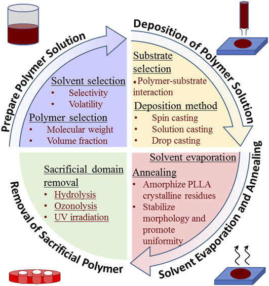
FIG. 5. Illustration of process flow for fabrication of nanoporous polymeric templates utilizing BCPs.
A. Preparing polymer solution
For PS-b-PLLA self-assembly, the gyroid morphology forms from low molecular weight BCP formulations at a PLLA volume fraction around 0.35. Reference Ho, Chiang, Chen, Wang, Hasegawa, Akasaka, Thomas, Burger and Hsiao42 At a similar volume fraction of 0.39, the PS-b-PLLA double gyroid morphology was produced using higher molecular weight polymer components (PS: 34 kg/mol, PLLA: 27 kg/mol). Reference Hsueh, Huang, Ho, Lai, Makida and Hasegawa2 Solvent annealing can also be used to facilitate the PS-b-PLLA assembly with improved lateral order. Reference She, Lo and Ho38,Reference She, Lo, Hsueh and Ho39 Block co-polymer molecular weight and polymeric volume fractions were found to directly affect the resultant template pore size and uniformity in the case of the hexagonal cylinder pore morphology Reference Ho, Chiang, Chen, Wang, Hasegawa, Akasaka, Thomas, Burger and Hsiao42,Reference Ho, Tseng, Fan, Chiang, Lin, Ko and Huang47 ; increasing the polymer block molecular weight yielded larger pores with improved homogeneity in pore size. Thus, the formulation or selection of the parent PS-b-PLLA polymer offers an opportunity for tuning the pore morphology and homogeneity in the resultant porous template.
As assembly of BCPs requires a high degree of chain mobility, liquidizing solvents facilitate the process of nanoscale domain separation between dissimilar copolymer species during evaporation processes. In turn, solvent choice, i.e., solvent selectivity and volatility, has a pronounced effect on the assembled morphology of BCPs. Reference Ho, Tseng, Fan, Chiang, Lin, Ko and Huang47 In the case of solution casting, PS-selective solvents (such as chlorobenzene, tetrahydrofuran (THF), and benzene), which more readily dissolve PS than PLLA, were found to induce a favorable BCP nano-assembly whereas neutral solvents did not yield an appreciable polymeric organization. Reference Ho, Tseng, Fan, Chiang, Lin, Ko and Huang47 It has been shown that PS-selective solvents with moderate volatilities (such as chlorobenzene with 12 mmHg vapor pressure) yielded more homogeneous nanoscale assemblies than those with high volatility. Reference Ho, Tseng, Fan, Chiang, Lin, Ko and Huang47 It can be hypothesized that the pore size uniformity is correlated with the permissible time for assembly before complete evaporation. As self-assembly time is largely limited to the time it takes the solvent to evaporate, the slower evaporation rates of lower volatility solvents provide more time for polymer organization. This increase in polymer organizational homogeneity with decreasing solvent volatility may have a lower bound somewhere below a solvent vapor pressure of 12 mmHg. Reference Ho, Tseng, Fan, Chiang, Lin, Ko and Huang47 In contrast to the PS-selective solvents prescribed for solution casting procedures, nonselective solvents demonstrated the ability to yield a template assembly when used in spin casting procedures. Reference Ho, Tseng, Fan, Chiang, Lin, Ko and Huang47 Volatile dichloromethane is commonly used to facilitate gyroid nano-assembly in the PS-b-PLLA system via spin casting. Reference Hsueh, Huang, Ho, Lai, Makida and Hasegawa2,Reference Ho, Tseng, Fan, Chiang, Lin, Ko and Huang47
B. Deposition of polymer solution on substrate
To obtain nanoscale organization within the PS-b-PLLA polymer system, a solution deposition and solvent evaporation process is required. Several deposition methods have been documented, each yielding a distinct template morphology. Spin casting methods may be used for the preparation of thin-film templates, with thicknesses between 30 and 200 nm. Reference Ho, Tseng, Fan, Chiang, Lin, Ko and Huang47 Adapting Lin et al.’s work with the PS-b-PEO system, Reference Lin, Kim, Wu, Boosahda, Stone, LaRose and Russell48 spin casting of a dilute (1.5 wt%) PS-b-PLLA polymer solution onto a silicon wafer was shown to provide sufficient kinetic energy for copolymer self-organization into a hexagonal cylinder morphology with uniformity in arrangement and size. Reference Ho, Tseng, Fan, Chiang, Lin, Ko and Huang47,Reference Lin, Kim, Wu, Boosahda, Stone, LaRose and Russell48 The spin casting procedure affords flexibility in choice of the polymer solvent, whereas solution casting methods largely require the use of PS-selective solvents. Reference Ho, Tseng, Fan, Chiang, Lin, Ko and Huang47 For the preparation of thicker microscale templates, solution casting has been used. Solution cast PS-b-PLLA at room temperature for a period of two weeks was shown to yield templates with a nanoscale double gyroid morphology and thickness on the order of centimeters. Reference Hsueh, Huang, Ho, Lai, Makida and Hasegawa2 Another possible method by which a polymer solution may be deposited on a substrate is drop casting, although it has not been widely applied to the PS-b-PLLA system. In the case of drop casting of the PS-P4VP polymeric system, Reference Liang, Hong, Guiochon, Mays and Dai49 self-assembly into the nanostructured hexagonal cylinder morphology was mediated by hydrogen bonding between the P4VP block and added resorcinol.
Substrate selection may also affect the final template morphology for the PS-b-PLLA system. In the case of thin-film templates (thickness <100 nm), polymer–substrate interactions (such as polar interactions of PLLA with the hydrophilic surface when using a glass substrate Reference Ho, Tseng, Fan, Chiang, Lin, Ko and Huang47 ) are likely to have a slight effect on the morphology of the final polymer templates. This typically is manifested by the preferential wetting of glass or other polar substrates by the PLLA block, forming a base layer of PLLA below the assembled BCP morphology. Despite the presence of this PLLA base layer, it has been found that organizational homogeneity of the remaining template nanostructure was not greatly affected. Reference Ho, Tseng, Fan, Chiang, Lin, Ko and Huang47 Similar morphology was reliably produced using a spin coating procedure for all the substrates tested, including glass slides, carbon-coated glass slides, indium tin oxide glass, silicon wafers, etc. Reference Ho, Tseng, Fan, Chiang, Lin, Ko and Huang47
C. Solvent evaporation and annealing
Evaporation of the solvent, typically requiring days in open air environments, can promote microphase separation in the polymer film. For example, a PLLA hexagonal cylinder morphology was partly attributed to differences in permeation between the PS and PLLA blocks, and the efficiency of solvent evaporation is enhanced with microphase-separated microdomains. Reference Ho, Tseng, Fan, Chiang, Lin, Ko and Huang47 Because this assembly process is mediated by evaporation at the film surface, there might be some limitations for assembled film thickness. Subsequent to the evaporation step, solid polymer thin films are sometimes further dried using a vacuum oven (e.g., in some cases they were desiccated for three days at 65 °C Reference Hsueh, Huang, Ho, Lai, Makida and Hasegawa2,Reference Ho, Tseng, Fan, Chiang, Lin, Ko and Huang47 ).
A commonly used annealing procedure for dried, phase-separated BCPs aims to convert structurally-disturbing crystalline PLLA back to its amorphous state to improve the microphase morphology. By heating to a temperature above the melting temperature of crystalline PLLA but below the Order–Disorder Transition (ODT) (i.e., 175 °C for 1–3 min), PLLA becomes amorphous within dried thin films; this acts to reduce the negative effect PLLA crystallinity has on the formation of the nanoscale morphology. Reference Hsueh, Huang, Ho, Lai, Makida and Hasegawa2,Reference Ho, Chiang, Chen, Wang, Hasegawa, Akasaka, Thomas, Burger and Hsiao42,Reference Ho, Tseng, Fan, Chiang, Lin, Ko and Huang47 While not a required processing step, an additional thermal annealing treatment of templates at a temperature below the ODT temperature promotes uniformity in structure, long-range order, and thermodynamic stability of the polymer morphology. Reference Ho, Chiang, Chen, Wang, Hasegawa, Akasaka, Thomas, Burger and Hsiao42,Reference Ho, Tseng, Fan, Chiang, Lin, Ko and Huang47,Reference Baruth, Seo, Lin, Walster, Shankar, Hillmyer and Leighton50,Reference Kim, Misner, Xu, Kimura and Russell51 It is critical that the ODT temperature is not exceeded during this heat treatment, or the polymer will reversibly transform back into a miscible melt. The ODT temperature for the PS-b-PLLA system ranges from ∼180 to 280 °C as the total polymer molecular weight is increased, Reference Ho, Chiang, Chen, Wang, Hasegawa, Akasaka, Thomas, Burger and Hsiao42 and is around 230–240 °C at the optimal total polymer molecular weight (13.3–15.0 kg/mol) for the formation of a gyroid nanostructure. A three hour anneal at 140 °C followed by rapid quench to room temperature was reported to aid morphological stabilization of various thin-film PS-b-PLLA structures. Reference Ho, Chiang, Chen, Wang, Hasegawa, Akasaka, Thomas, Burger and Hsiao42 Alternatively, environmentally controlled solvent vapor annealing methods have demonstrated success in promoting morphological homogeneity and lengthening the span of the organization to nearly 10 μm for similar BCP systems (e.g., PS-b-PLA). Reference Baruth, Seo, Lin, Walster, Shankar, Hillmyer and Leighton50
D. Selective removal of PLLA
To complete the process of fabricating sacrificial porous PS templates for metallization, PLLA nanodomains must be selectively removed from the assembly. It is common practice to hydrolyze PLLA with a solution of sodium hydroxide, such as a 0.5 M NaOH solution prepared with a 40/60 volumetric mixture of methanol and water. Reference Hsueh, Huang, Ho, Lai, Makida and Hasegawa2 Complete PLLA removal requires days to allow for sufficient percolation of the solution through the developing pores. The porous PS templates may be recovered from the hydrolyzing solution by using cell strainers. Gently washing the templates with dilute methanol is permissible. Reference Hsueh, Huang, Ho, Lai, Makida and Hasegawa2 For the PS-b-PI system, PI domains were selectively degraded by ozonolysis, i.e., by exposing the film to an atmosphere of ozone at room temperature for 24 h and subsequently soaking the film in ethanol. Reference Hashimoto, Tsutsumi and Funaki41 PMMA was removed from PS-b-PMMA BCPs by the application of UV irradiation followed by rinsing. Reference Thurn-Albrecht, Steiner, DeRouchey, Stafford, Huang, Bal, Tuominen, Hawker and Russell52
The process for fabricating porous PS templates from PS-b-PLLA polymer solutions is inherently time-consuming (it can take up to a month Reference Hsueh, Huang, Ho, Lai, Makida and Hasegawa2 ) and is highly sensitive to processing parameters. Nonetheless, it provides a feasible pathway to the attainment of structurally homogeneous nanoporous templates. With the continued realization of improvements to the outlined process, this method will continue gaining utility for the creation of nanoscale structures.
IV. METALLIZATION OF NANOPOROUS POLYMERIC TEMPLATES
A. Overview of metallization methods
The polymer template-based method for nanoporous metal fabrication involves a metallization procedure in which a metal must be deposited into tortuous nanopores. Physical vapor deposition is a viable option, although the line-of-sight method may encounter challenges in the infiltration of narrow or tortuous template pores. Reference Jeske, Schultze, Thönissen and Münder34 Although promising, chemical vapor deposition processes have yet to be fully explored in the context of nanoporous metal fabrication. Reference Delhaes53 Standard electroplating of complex geometries may yield poor uniformity of metallization because the localized current density varies across surfaces. Reference Jeske, Schultze, Thönissen and Münder34,Reference Parkinson54 However, electrodeposition of Au and Pt into polymeric templates was successfully demonstrated. Reference Vignolini, Yufa, Cunha, Guldin, Rushkin, Stefik, Hur, Wiesner, Baumberg and Steiner7,Reference Crossland, Ludwigs, Hillmyer and Steiner55 Electrochemical deposition of Au into pore space of the PS-polyethylene oxide (PEO) template involved a nucleation step (1–3 cyclic voltammetry scans between 0 and −1.2 V at a rate of 50 mV/s) and a deposition step (at a fixed potential of −0.8 V for 100 s); the resulting nanoporous Au structure is promising as a 3D optical metamaterial with reduced plasma frequency compared to solid Au. Reference Vignolini, Yufa, Cunha, Guldin, Rushkin, Stefik, Hur, Wiesner, Baumberg and Steiner7 Electrodeposition of Pt into poly(4-fluorostyrene) (PFS) templates was carried out in one step with the working electrode at 0.1 V in a standard 3-electrode cell using a Cl6H2Pt solution. Reference Crossland, Ludwigs, Hillmyer and Steiner55
Electroless metal plating is a common method by which template metallization is achieved in the literature. Reference Takeyasu, Tanaka and Kawata56 It involves auto-catalyzed electrochemical reactions in an ionic solution that enables enhanced infiltration of narrow pores. Reference Jeske, Schultze, Thönissen and Münder34,Reference Ronkel, Schultze and Arens-Fischer35,Reference Takeyasu, Tanaka and Kawata56 Electroless plating is attractively generalizable to a wide range of metals: nickel, Reference Hsueh, Huang, Ho, Lai, Makida and Hasegawa2,Reference Hashimoto, Tsutsumi and Funaki41,Reference Brenner and Riddell57 copper, Reference Paunovic58 gold, Reference Takeyasu, Tanaka and Kawata56 silver, Reference Takeyasu, Tanaka and Kawata56 cobalt, Reference Brenner and Riddell57 and iron. Reference Dinderman, Dressick, Kostelansky, Price, Qadri and Schoen59 In particular, extensive research has been conducted for the electroless plating of nickel onto various polymer substrates. Reference Wang, Ji and Lee60 Excellent uniformity in thickness of the deposited nickel and coverage of complex geometries can be obtained. Reference Parkinson54
B. Electroless plating
Hashimoto et al. Reference Hashimoto, Tsutsumi and Funaki41 and Hsueh et al. Reference Hsueh, Huang, Ho, Lai, Makida and Hasegawa2 have reported successful electroless plating of nickel onto porous polystyrene (PS) with pore sizes below 50 nm. Figures 6(a) and 6(b) show Transmission Electron Microscopy (TEM) images of PS–Ni gyroid nanohybrids reported in Refs. Reference Hashimoto, Tsutsumi and Funaki41 and Reference Hsueh, Huang, Ho, Lai, Makida and Hasegawa2, respectively. In both cases, the prior pore space in PS was replaced with Ni. Electroless Ni plating was also applied to nanoporous PS templates where PS structs were covered with a layer of poly(4-vinylpyridine) (P4VP), which is hydrophilic and facilitates the penetration of water-based plating reagents into the pore channel. Reference Vukovic, Punzhin, Vukovic, Onck, De Hosson, ten Brinke and Loos61 A bright-field TEM image of the Ni-plated PS/P4VP template is shown in Fig. 6(c). Homogeneous distribution of Ni seen in Fig. 6(c) suggests that the prior pore space is well connected and is accessible for the plating solution. Ni was also successfully plated into nanochannels in a bicontinuous double gyroid template containing PS, Reference du Sart, Vukovic, Vukovic, Polushkin, Hiekkataipale, Ruokolainen, Loos and ten Brinke62 as shown in Fig. 6(d).

FIG. 6. TEM images of polymer-nickel gyroid nanohybrids without staining (Ni domains appear dark) reported in Refs. Reference Hsueh, Huang, Ho, Lai, Makida and Hasegawa2, Reference Hashimoto, Tsutsumi and Funaki41, Reference Vukovic, Punzhin, Vukovic, Onck, De Hosson, ten Brinke and Loos61, and Reference du Sart, Vukovic, Vukovic, Polushkin, Hiekkataipale, Ruokolainen, Loos and ten Brinke62 (reproduced with permissions). These images were taken after electroless plating of Ni into nanochannels in the porous template but before removal of polymer template. The polymer templates are PS Reference Hsueh, Huang, Ho, Lai, Makida and Hasegawa2,Reference Hashimoto, Tsutsumi and Funaki41 in (a, b), PS/P4VP Reference Vukovic, Punzhin, Vukovic, Onck, De Hosson, ten Brinke and Loos61 in (c), and PtOS/PS/P4VP Reference du Sart, Vukovic, Vukovic, Polushkin, Hiekkataipale, Ruokolainen, Loos and ten Brinke62 in (d).
1. Electroless deposition process
Figure 7 presents the process flow for metallization of nanoporous polymeric templates by electroless deposition. Electroless plating of nickel onto polymer is generally performed in three steps: sensitization, activation, and plating. Reference Hashimoto, Tsutsumi and Funaki41 The sensitization and activation steps prepare the polymeric template surfaces for metallization.
-
(i) Sensitization of nanoporous PS substrates is the primary enabler of the metallization process and can be performed in several ways. Traditionally, PS templates have been sensitized utilizing SnCl2 as a seeding agent for the activation step, i.e., the templates were soaked in an aqueous solution of SnCl2. However, this depends on the ability of Sn2+ ions to adhere to the surface of the nanochannels in the template. Reference Hashimoto, Tsutsumi and Funaki41 An alternative sensitization process employs a surface modification technique that enhances the ability of metallizing ions to adhere to the pore surfaces. For example, through soaking PS templates in poly(allylamine hydrochloride) (PAH) for 30 min, PAH attachment to the surfaces reduces hydrophobicity and permits subsequent seeding during activation. Reference Wang, Ji and Lee60 Similar surface modification approaches have been demonstrated for bulk ABS Reference Garcia, Berthelot, Viel, Mesnage, Jégou, Nekelson, Roussel and Palacin63 and PP Reference Tengsuwan and Ohshima64 and could be applicable to many more polymeric species.
-
(ii) Following sensitization, templates are immersed in a palladium solution (commonly PdCl2 or Na2PdCl4) for activation. For the Sn-based sensitization method, this activation process is achieved via a redox reaction in which Pd is reduced on the surface of the template, and Sn2+ ions previously adsorbed on the nanochannel surfaces are converted to Sn4+. It has been shown that the Sn sensitization step may not be necessary for the electroless plating of nickel onto porous PS templates Reference Hsueh, Huang, Ho, Lai, Makida and Hasegawa2 ; in this case, the sensitization step is foregone and Pd ions directly adhere to the porous templates. However, it was shown in a different study that appreciable Pd attachment to a bulk PS surface is not possible without template sensitization due to the hydrophobic nature of polymer surfaces. Reference Wang, Ji and Lee60 Following the PAH surface modification sensitization method, Pd ions are directly adhered to the PAH-modified pore surfaces in the PS template. The imbedded palladium seeds within the porous template structure act as nuclei for subsequent nickel plating.
-
(iii) Upon introducing activated templates to an ionic nickel plating bath, nickel ions are reduced at palladium sites where Pd acts as catalyst of the reduction of Ni2+ to Ni. In general, electroless plating processes are auto-catalyzed as redox reactions. Because nanoporous metal templates have high specific surface areas, plating often requires refreshing of the Ni bath to avoid drastic Ni ion depletion in solution. Reference Aleksinas, Mallory and Hajdu65
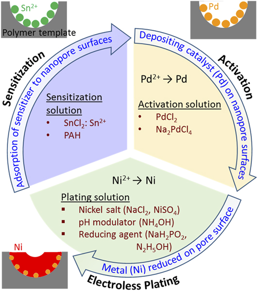
FIG. 7. Illustration of the process flow for metallization of nanoporous polymer templates by electroless plating of nickel.
2. Kinetics of electroless deposition
Properties of the plating bath, such as temperature, pH, and reducing agent content, have a strong effect on plating kinetics. Most electroless plating baths contain common functional components: an ionic metal in solution to be plated, a pH modulator, and a reducing agent. (i) In the case of electroless nickel plating, it is common to employ hydrated nickel salts (i.e., NiCl2·6H2O, NiSO4·6H2O) for supplying nickel ions. Reference Hsueh, Huang, Ho, Lai, Makida and Hasegawa2,Reference Zhang, Wu and Zhao66 (ii) Bath pH is typically controlled via addition of liquid ammonia. Reference Hsueh, Huang, Ho, Lai, Makida and Hasegawa2,Reference Zhang, Wu and Zhao66 In general, basic solutions provide optimal plating kinetics for electroless nickel deposition. Reference Zhang, Wu and Zhao66,Reference Guo, Jiang, Yuen, Ng, Lan and Zheng67 (iii) Nickel plating can be driven through the addition of reducing agents, such as sodium hypophosphate, to the bath. Reference Parkinson54 Sodium hypophosphite is commonly used to improve reduction kinetics of plating at the appropriate concentrations, but it is known to introduce phosphorous content to the plated nickel metal. Reference Zhang, Wu and Zhao66 Hsueh et al. used hydrazinium hydroxide as an alternative reducing agent; they also added ethanol to their plating bath, likely to promote wetting of the nanopores for a successful deposit. Reference Hsueh, Huang, Ho, Lai, Makida and Hasegawa2
Understanding the reaction kinetics of electroless Ni plating procedures is crucial for sufficient metallization of PS templates but is challenging due to the complexity of plating baths and the large number of variables that affect plating (e.g., substrate, pretreatment method, temperature, pH, reducing agent concentration). Variation in nickel adhesion to various substrates adds additional complexity. Plating kinetics for nickel onto PS is not well documented in the literature. However, general processing insights can be gleaned from experiments conducted for electroless Ni plating of alternative substrates. Zhang et al. found that surface treatment sensitizing procedures (such as those previously described) can affect an almost 3-fold increase in the Ni plating rate and improve deposit uniformity onto hollow glass spheres. Reference Zhang, Wu and Zhao66 The optimal pH for Ni plating of glass spheres was reported to be 12. Reference Zhang, Wu and Zhao66 An even more dramatic increase in the plating rate was evidenced for bulk PS substrates sensitized with PAH when compared to the baseline. Reference Wang, Ji and Lee60 Normalizing to surface area, electroless Ni plating onto bulk PS has been demonstrated at a rate of approximately 1.3 µm/h. Reference Wang, Ji and Lee60 Guo et al. discovered a common trend in plating kinetics with temperature, pH, and reducing agent concentration for electroless Ni plating onto polyester fibers; as each parameter was increased, nickel deposition rates steadily increased before reaching a maximum [on the order of 20 mg/(cm2 h)] and then subsequently decreased. Reference Guo, Jiang, Yuen, Ng, Lan and Zheng67 The optimal plating conditions were found to be 80 °C, pH = 8.5, and [NaH2PO2] = 40 g/L, respectively. Reference Guo, Jiang, Yuen, Ng, Lan and Zheng67 Furthermore, an empirical kinetic equation taking the form of Eq. (1) was developed in this study and validated by experimental data.
 $$v = a \cdot \exp \left[ {b{{\left( {T - 333} \right)} \over T}} \right]\left( {\prod\limits_i {{{\left[ {{X_i}} \right]}^{{n_i}}}} } \right)\quad ,$$
where v is the deposition rate, T is the temperature, and [X i ] denotes the concentration of the ith ion.
V. REMOVAL OF POLYMERIC TEMPLATES
Subsequent to metallization, the polymeric templates themselves must be sacrificially removed from the metallized assembly. There are several possible methods to remove the template.
-
(i) Polymer dissolution in volatile solvents, such as tetrahydrofuran (THF), are commonly used, and the process can take over twenty hours. Reference Hsueh, Huang, Ho, Lai, Makida and Hasegawa2 After sufficiently metalizing nanoporous gyroid PS templates by electroless deposition and selective dissolution of the PS scaffold, nanoporous Ni structures are obtained, [see Fig. 8(a)] and their structural stability has been demonstrated. Reference Hsueh, Huang, Ho, Lai, Makida and Hasegawa2
-
(ii) Template removal may also be accomplished by decomposition of polymer at elevated temperatures (pyrolysis). For example, after electroless plating of Ni into the PS/P4VP template, the template was removed by heating at 350 °C while keeping the Ni structure intact as shown in Fig. 8(b). Reference Vukovic, Punzhin, Vukovic, Onck, De Hosson, ten Brinke and Loos61
-
(iii) Plasma etching has also been utilized to remove polymer templates. Figure 8(c) shows nanoporous Au obtained from electrodeposition of Au into the PS/PEO template and template removal by plasma etching, Reference Vignolini, Yufa, Cunha, Guldin, Rushkin, Stefik, Hur, Wiesner, Baumberg and Steiner7 and Fig. 8(d) shows nanoporous Pt from electrodeposition of Pt into the PFS template and removal of PFS by O2 plasma etching. Reference Crossland, Ludwigs, Hillmyer and Steiner55 In both cases, template removal was considered successful, revealing stable nanoporous metallic structures.

FIG. 8. SEM images of nanoporous metals after removal of polymeric templates (adapted from Refs. Reference Hsueh, Huang, Ho, Lai, Makida and Hasegawa2, Reference Vignolini, Yufa, Cunha, Guldin, Rushkin, Stefik, Hur, Wiesner, Baumberg and Steiner7, Reference Crossland, Ludwigs, Hillmyer and Steiner55, and Reference Vukovic, Punzhin, Vukovic, Onck, De Hosson, ten Brinke and Loos61 with permissions). (a) Nanoporous Ni from electroless deposition of Ni into porous PS template followed by template dissolution. Reference Hsueh, Huang, Ho, Lai, Makida and Hasegawa2 (b) Nanoporous Ni from electroless deposition of Ni into PS/P4VP template and template was removed by pyrolysis. Reference Vukovic, Punzhin, Vukovic, Onck, De Hosson, ten Brinke and Loos61 (c) Nanoporous Au from electrodeposition of Au into the PS/PEO template and template removal by plasma etching. Reference Vignolini, Yufa, Cunha, Guldin, Rushkin, Stefik, Hur, Wiesner, Baumberg and Steiner7 (d) Nanoporous Pt from electrodeposition of Pt into the PFS template and removal of the template by O2 plasma etching. Reference Crossland, Ludwigs, Hillmyer and Steiner55
The nanopore size is highly uniform in each nanoporous metal shown in Fig. 8, and the pore size is around 40 nm in Figs. 8(a) and 8(d) and 20 nm in Figs. 8(b) and 8(c).
VI. CONCLUSIONS AND OUTLOOK
NPMs with novel properties, e.g., high surface area, high specific strength, and nontraditional functional behavior, are positioned to stimulate the applicability of metals in new high-performance applications. However, there are fundamental challenges in the fabrication of porous metallic materials with nanoscale pore sizes and interconnectivity. In this article, we present a critical review of nanoporous metal fabrication. We have briefly discussed traditional methods such as combustion and electrodeposition which typically do not produce nanoscale pores in metals, as well as the dealloying method, which has demonstrated success in producing nanoscale pores but typically leads to a wide pore size distribution and is mainly limited to noble metals. We have primarily focused on templating methods for nanoporous metal fabrication, which offer a wider range of applicable metals while enhancing control of the metallic pore morphology. Metals are introduced into the pore spaces of sacrificial nanoporous templates by deposition or infiltration, and subsequent removal of the templates yields nanoporous metals. While hard templating processes are also feasible, soft polymeric templates are most frequently used. The most common are nanoporous PS templates with the double gyroid structure obtained from the PS-b-PLLA block co-polymer system. Metallization of the porous polymer templates can be carried out by a variety of methods, although electroless plating has been the most commonly used method. Electroless plating permits uniform plating by many metallic species. Preparation of polymer templates and their subsequent metallization have been discussed at length.
The utility of the polymer template-based method for fabricating nanoporous metals has yet to be fully realized. The development of methods for increasing the assembly depth of BCP films and, therefore, the thickness of template samples to the micron-scale will further improve the applicability of porous metals in various applications. Electroless plating of high surface area and nanostructured polymeric templates are not well understood; future work is required for providing a quantitative understanding of this process through study of pore penetration and template attachment by different metallic species. Development of porous template-compatible physical or chemical vapor deposition methods could also provide attractive alternative methods by which templates can be metalized. Additionally, mechanical and functional characterization of nanoporous metals is also an important area for investigation.
ACKNOWLEDGMENTS
This work was primarily supported by the RPI start-up fund. T. Rebbecchi was also partially supported by the U.S. National Science Foundation grant DMR #1352524.


 Open access