


DISCUSSION POINTS
-
• Water splitting will be a central challenge for any future fossil fuel-free energy infrastructure that relies on liquid or gaseous chemical fuels.
-
• While the main materials challenge for solar- and wind-driven electrolysis is the development of better catalysts, the main challenge for photoelectrochemical water splitting is to find new chemically stable optimal-bandgap semiconducting light absorbers.
-
• Further progress in the development of photo-driven water splitting generators requires significant additional efforts in electrochemical engineering and the development of standardized methods for benchmarking device performance and stability.
Introduction
There has been a world-wide effort in the last decade to accelerate the progress of research on converting and storing solar energy especially in the form of chemical bonds. Major centers for solar fuels research, and programs within the national science foundations and energy departments, have been funded to attack this problem with a total world-wide expenditure of over $750M. 1 Attainment of the noble goal of having a greenhouse gas-free energy economy depends on the fact that solar fuels have to compete with extracting reduced carbon or hydrocarbon fuel sources. Currently, the extraction of these resources does not require a large capital investment in covering large areas with solar collectors for the generation of energetic electrons and holes since much of the investment is already in place. Therefore, without the governments of the world putting a price on CO2 emissions, either with a carbon tax or cap and trade policy, solar fuels will not be economically viable until these carbon-based resources are largely depleted and the climate will have been severely impacted. At this point, however, this large investment in solar fuels research has not yet produced even a prototype system that is scalable, cost effective, efficient, and stable as determined by a certification process like that for photovoltaic devices. Recently reported devices that arguably come closest to this goal are integrated photovoltaics-driven electrolysis devices. One example is a 64 cm2 modular demonstrator based on triple-junction silicon cells with an efficiency of 3.9% and a lifetime of more than 40 h. Reference Turan, Becker, Urbain, Finger, Rau and Haas2 PV-driven devices based on III–V semiconductors show higher efficiencies but are more expensive and do not have a scalable design. Reference May, Lewerenz, Lackner, Dimroth and Hannappel3 At the other end of the spectrum are oxide-based devices, which can be cheap but show poor efficiencies. Reference Bornoz, Abdi, Tilley, Dam, van de Krol, Grätzel and Sivula4 Further development of these preprototype systems is needed as a precursor to the required industrial level scale-up to enable solar fuels to have a real impact. In this perspective, we will attempt to evaluate where the field has progressed and where there is still a need for breakthroughs to produce a viable solar fuels industry.
The need for water splitting in a fossil fuel-free society
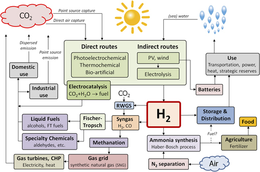
The sustainable production of hydrogen is the central challenge for any future clean energy infrastructure that relies on chemical fuels as energy carriers. Ideally, such fuels should be in liquid or gaseous form so that they are easily transported, stored, and used. Not all such chemical fuels contain carbon or nitrogen, but all of them contain hydrogen. Since water is the only universally available, abundant, and sustainable source of hydrogen on the planet, water splitting with sunlight is the key challenge. Figure 1 illustrates a future energy infrastructure in which water splitting plays a central role. While such a completely fossil fuel-free infrastructure is unlikely to become a reality by mid century, many of its components are already in place at a large scale and others will need to be implemented in the near future to assure that they can be scaled up in a timely fashion. The figure also illustrates that hydrogen is an essential base chemical in our food supply chain; without it, we would not be able to make the amounts of fertilizers needed to grow enough food for the world’s population. We often forget that we depend on fossil fuels not only for our energy supply but also for our food supply.

Figure 1. Illustration of a future energy infrastructure based on the renewable and fossil-free conversion of solar energy into a variety of carbon-, nitrogen-, and hydrogen-based chemical fuels. Water splitting, either via direct or indirect routes, plays a crucial role in this scenario. The hydrogen produced via these routes can be fed into the already existing large-scale infrastructure for methanation and Fischer–Tropsch syntheses by reacting it with CO2 to form syngas via the reverse water-gas-shift (RWGS) reaction.
Direct versus indirect routes
Photochemical pathways toward renewable fuel production have always been and may always be in competition with photovoltaics (PV) or wind energy coupled with water electrolysis units. These indirect photo-driven electrolysis systems are already commercially available and offer a way to compensate for the intermittency of solar and wind energy by storing the generated energy in the form of hydrogen. The highest reported efficiency for this approach is an impressive 30% for a system composed of two series-connected PEM electrolyzers driven by a triple-junction solar cell. Reference Jia, Seitz, Benck, Huo, Chen, Ng, Bilir, Harris and Jaramillo5 The argument for direct solar photoelectrolysis, in which light absorption and electrocatalysis are integrated into one device, has always been that one system would be cheaper than a system composed of two or more separate devices, i.e., PV connected to electrolyzers. The reasoning is that the costs of the glass, frames, internal wiring and connections, etc. for each of the individual devices are higher than those of the active components, i.e., the silicon in the PV device and the electrodes and membranes in the electrolyzer. Thus, integration could reduce the overall costs, as is often the case in some multifunction devices such as the combination of a printer, scanner, and fax machine.
While this argument remains valid at the panel or module level, it should be realized that individual component costs make up an increasingly small part of the total system costs. The price of photovoltaic solar panels has fallen dramatically to where now the balance of systems (BOS) costs (external wiring, supports, inverter, permits, etc.) are more than the cost of the panels. Reference Chung, Davidson, Fu, Ardani and Margolis6 The cost of electrolyzers will likely be brought down significantly with further research and the economies of scale. Indeed, large electrolyzers are used to convert excess hydropower-to-hydrogen in Norway and are currently being installed for other uses in other parts of the world such as wind energy storage in the north of Germany. One should also consider that BOS costs for collecting hydrogen with pipes and membranes over large solar collection areas will likely be much higher than those for a PV-electrolysis installation (even though there may be some savings on the inverters). The most recent estimate for H2 production costs via PEM electrolysis is $3.40–$6.60/kg H2 in 2007 US dollars, assuming a variability of $0.03–$0.08 per kW h in electricity costs. Reference Miller, Ainscough and Talapatra7 These electricity prices can nowadays indeed be achieved with PV, as illustrated by a recent successful bid for a 50 MW solar PV field in Europe for 5.38 €ct/kW h. 8 The hydrogen production costs for integrated solar fuel generators are likely to be higher and have been estimated in several studies. Reference Newman, Hoertz, Bonino and Trainham9–Reference Pinaud, Benck, Seitz, Forman, Chen, Deutsch, James, Baum, Baum, Ardo, Wang, Miller and Jaramillo11 One often cited study estimates a cost of $10.40/kg H2 assuming a solar-to-hydrogen efficiency of 10%, a panel cost of $153/m2, and a lifetime of 10 years. Reference Pinaud, Benck, Seitz, Forman, Chen, Deutsch, James, Baum, Baum, Ardo, Wang, Miller and Jaramillo11 Last but not least, there are significant advantages to generating the amount of hydrogen at the desired pressure on demand where and when it is needed. This is relatively easy to do with electrolyzers, but safely generating high pressures over large solar collection areas comes with serious engineering challenges.
There are, however, also several advantages to be gained by integrating light absorption and electrocatalysis into one single device. One advantage is the relatively small current densities in photoelectrochemical (PEC) devices (10–20 mA/cm2), about 100 times smaller than the current densities in commercial electrolyzers (1–2 A/cm2). This increases the internal electrolysis efficiency, enabling integrated systems to outperform PV-electrolyzer systems. Reference Haussener, Hu, Xiang, Weber and Lewis12 Furthermore, the greatly reduced demands on the catalysts may enable the usual Pt- and IrO x -based catalysts to be replaced with low-cost, earth-abundant alternatives. While noble metals currently represent a minor fraction of the cost of the whole electrolysis unit, this is likely to change when the technology is implemented on a multi GW scale. Lower current densities also reduce the loss of the active electrode area due to the presence of gas bubbles. The second advantage of integrated devices is heat management. Assuming (optimistically) an energy conversion efficiency of 20% and reflection losses of 10%, more than 70% of the incoming radiation will be converted into heat. In photovoltaic devices, this can lead to operating temperatures of 60–80 °C and efficiency losses upwards of 10%. Reference Würfel13 In PEC devices, these losses will be much smaller due to effective cooling by the electrolyte solution, especially when using convective flow. Reference Tembhurne and Haussener14 Moreover, higher temperatures enhance the electrochemical reaction kinetics by roughly a factor of 2 per 10 °C increase (Arrhenius’ law). Recent studies have shown that the improvement in the kinetics is larger than the decrease in the photovoltaic properties of the PEC absorber. Reference Haussener, Hu, Xiang, Weber and Lewis12,Reference Ye, Melas-Kyriazi, Feng, Melosh and Chueh15
In summary, it appears to be likely that solar- or wind-driven (indirect) electrolysis will be the sustainable hydrogen production technology of choice for the short-to-medium term (i.e., until mid century). In the medium-to-long term, new device concepts and materials that would benefit from the advantages offered by direct photoelectrolysis routes should be explored.
Water splitting versus CO2 reduction
If photoelectrochemical systems can be developed and optimized for performance and price, then hydrogen is the preferred product rather than the direct reduction of CO2. The many reasons for this are spelled out in a previous article by one of the authors. Reference Parkinson16 The arguments are summarized here as well in Table 1.
Table 1. Practical reasons for not doing direct (photo)electrochemical reduction of CO2.

It is clear that direct solar hydrogen generation is quite difficult to accomplish, but it is still much easier than direct CO2 reduction. If one would be able to develop a cost-effective system for renewable hydrogen, it will have an immediate and direct impact on the transportation sector (if fuel cell vehicles become widespread) and on ammonia production. Ammonia production is now a leading CO2 emission source since it consumes 1–2% of the world’s energy supply and almost all the hydrogen comes from either coal gasification (China) or methane reformation. Reference LeCompte18,19 For fueling conventional hydrocarbon-burning vehicles, one might argue that the renewable electrons from sunlight or wind would be better stored directly in the battery of electric vehicles that will be plentiful in the future rather than trying to produce liquids with complex chemistry.
In summary, fundamental research on CO2 reduction is an interesting academic problem but is without a clear path to near term implementation on a large scale; therefore, we argue that it is not practical, nor advisable at this time or the near future, to use renewable energy to directly reduce carbon dioxide produced from burning fossil fuels to reduce CO2 emissions or from the atmosphere to reduce atmospheric concentrations. Instead the better approach, to achieve a renewable fuel-based future energy economy in the urgently needed short timescale, is through the renewable generation of hydrogen. This hydrogen can be used directly in combustion processes (e.g., as additive to other less hydrogenated carbon sources to reduce their greenhouse footprints), in fuel cells, and in chemical processes that now use nonrenewable hydrogen (see, e.g., the left-hand side of Fig. 1).
Alternative photoelectrochemical storage systems
Recently, there has been a resurgence in the incorporation of energy storage within a photoelectrochemical system. Reference Yu, McCulloch, Huang, Trang, Lu, Amine and Wu20,Reference Wedege, Azevedo, Khataee, Bentien and Mendes21 This concept was demonstrated by the Weizmann Institute group in the late 1970s where they incorporated an additional battery electrode to make a three-electrode photoelectrochemical solar cell, where the electrical output could be split between charging the battery redox system and output during daylight and discharging the battery in the dark. Reference Manassen, Hodes and Cahen22 The Texas Instruments system for HBr photoelectrolysis was another example where inexpensive silicon microspheres with p–n and n–p junctions were incorporated into panels to produce hydrogen and Br2 in the solution which flowed over the panels. The products were then stored to be recombined in a H2/Br2 fuel cell during nondaylight hours to produce electrical power. After several hundreds of millions of dollars invested, the project was discontinued due to low oil prices and corrosion issues related to storing and flowing hot HBr/Br3 − solutions. Most of the technology around this system is described in the patent literature. Reference Porter, Lathrop and Kilby23,Reference Porter, Lathrop and Kilby24 Many years ago, one of the authors also investigated the efficiency and energetics of p–n systems for photoelectrolysis of haloacids. Reference Fornarini, Nozik and Parkinson25
A similar concept, that is essentially a solar chargeable redox flow battery, is shown in Fig. 2. Instead of trying to split water, the system would work with two kinetically fast one-electron redox couples such as the V3+/V2+ and V4+/V5+ couples currently favored in redox flow batteries, but many other redox couple combinations are possible. The additional feature is that when one looks at the system, with its flowing liquid over flat plate collectors, it appears very much like a solar thermal hot water system. So why not take the 80–85% of the solar energy that is not collected as stored redox energy and utilize the heat. Adding antifreeze to the electrolyte and incorporating a heat exchanger would essentially mimic the operation of a conventional low-grade hot water/space heating system. Table 2 summarizes the many advantages such a system would have over the much more difficult to accomplish solar water splitting system. In fact, the system could also be used to generate hydrogen on demand by passing the highly reducing V2+ electrolyte over a catalytic hydrogen evolving electrode such as platinum with the reduction of V5+ to V4+ at the other electrode since a vanadium redox flow battery can have an open circuit voltage of up to 1.5 V. Again, one must consider whether a combined system out-performs two separate systems that can be optimized separately.

Figure 2. Left: Schematic drawing of the system showing the concept for solar collection and conversion to electricity and stored heat. During charging, a photooxidation reaction will be driven on an n-type semiconductor at one side of the collector, and a photoreduction reaction will be driven on the other electrode by the light that penetrates the front electrode. The infrared light passing through both semiconductors is absorbed by a black absorber at the back of the electrolyte to further heat the electrolyte. Discharge to release the stored electrical energy is accomplished by driving the semiconductors into accumulation using valves to reverse the flow and expose the n-type material to the highly reducing redox electrolyte, while the p-type material is exposed to the highly oxidizing electrolyte. Middle: Side view of one potential design for the solar collector showing the absorbers that are back to back in a tandem configuration on a single glass plate coated on both sides with a conducting transparent oxide. The light path and redox electrolyte flow are also shown. Right: Front view of a potential design for the solar collector showing a pattern of absorbers (maroon) and ion selective membranes (blue) that permit the flow of the counter ions needed to sustain electroneutrality during redox reactions. The redox electrolyte on the front electrode would have to be mostly transparent whereas the electrolyte on the back electrode could be colored.
Table 2. Summary of eight potential advantages of a hybrid solar electrical/thermal storage system compared to water splitting.
Research needs for photoelectrochemical fuel production
Research in the field of photoelectrochemical energy conversion has recently bifurcated in two directions: discovering and developing new materials with proper band gaps and high stability to photocorrosion in electrolytes and depositing corrosion-resistant protection layers on well-established PV materials. Reference Hu, Lewis, Ager, Yang, McKone and Strandwitz26 The former represents the traditional semiconductor/electrolyte junction where the charge separating junction forms spontaneously upon immersion into the electrolyte, whereas the latter is essentially immersing a solar cell into the electrolyte since the charge/separating junction is isolated from the electrolyte. The authors would prefer that the term photoelectrochemical device be reserved for systems with a true semiconductor/electrolyte interface. This is not to say that the photoelectrochemical device is a preferred configuration since if a buried junction device can be made efficient, stable, and cost effective, it would be a very important advance.
There are some advantages to the liquid junction in a photoelectrochemical device (Table 3). One is that junction formation is perfectly conformal, enabling nanostructuring of the absorber material. Nanostructuring has the advantage of expanding the use of materials with nanometer scale diffusion lengths and lower absorption coefficients since the photogenerated carriers can be created within a diffusion length of the interface as well as extending the space charge layers deeper into the interior of the material. The large surface areas also reduce the turnover rates for any needed catalyst layers that will decrease overpotential losses. This would enable the use of less active, but cheap and earth-abundant catalysts instead of the traditional noble metal candidates. The disadvantage is that the photovoltage would be reduced due to the lower local light intensities (since the photovoltage depends logarithmically on light intensity). Reference Würfel13 One still needs carrier lifetimes on the order of 20 nanoseconds or more for nanostructuring to be effective. One cannot ‘picostructure’ to compensate for the picosecond carrier lifetimes that are being measured in some semiconducting oxides.
Table 3. Comparison of semiconductor–liquid junctions versus buried junctions.

Several demonstrations of integrated photoelectrochemical devices with buried junctions have recently been reported. Although the active areas are typically small, <0.5 cm2, impressive efficiencies (up to 14%) and lifetimes of up to several days have been reached. Reference May, Lewerenz, Lackner, Dimroth and Hannappel3,Reference Verlage, Hu, Liu, Jones, Sun, Xiang, Lewis and Atwater27 These devices are still in an early stage of development and so, it is yet unknown whether they can provide the very long-term stabilization necessary for a practical device. To produce such devices at scale would be technologically challenging since any pinholes or damage in the ultrathin coatings would result in undercutting corrosion and catastrophic failure. However most of the highest efficiency devices available today already depend on costly multijunction solar cell structures with highly optimized thin protection layers.
Materials
The key active components in a water splitting device are the light absorber(s) and the electrocatalysts. Many research efforts are currently being devoted to the latter, and several efficient and earth-abundant candidates for the hydrogen evolution reaction (HER) over a range of acidic and alkaline conditions are now available. Reference McCrory, Jung, Ferrer, Chatman, Peters and Jaramillo28 Earth-abundant candidates for the more difficult oxygen evolution reaction (OER) in alkaline conditions and near-neutral pH have also been identified. Reference McCrory, Jung, Ferrer, Chatman, Peters and Jaramillo28,Reference Kanan and Nocera29 What is still missing are earth-abundant candidates for the OER in acidic conditions. While further improvements of OER and HER catalysts are most definitely needed for the development of electrochemical energy storage devices, Reference Seh, Kibsgaard, Dickens, Chorkendorff, Norskov and Jaramillo30 we will argue below that the main bottleneck for a true photoelectrochemical device is not the catalyst but the light absorber.
To generate the minimum voltage of ∼1.5 V needed to split water (1.23 V + overpotentials), one needs at least two different light absorbers that are electrically connected in series. The highest efficiencies can be obtained with a tandem configuration, in which the bottom and top absorbers absorb complementary parts of the solar spectrum. It has been pointed out many times that the ideal bandgaps for such a dual absorber system are around 1.2 and 1.8 eV. Reference Seitz, Chen, Forman, Pinaud, Benck and Jaramillo31–Reference Hu, Xiang, Haussener, Berger and Lewis33 Slightly different band gap combinations may be optimal for the aforementioned solar-driven redox flow battery since the difference between the two redox reactions may be more or less than 1.23 eV, and overpotential losses will be less. Silicon (E g = 1.12 eV) is close to being an ideal bottom absorber and has already reached the phase of technological maturity. The missing material is a chemically stable top absorber with a band gap of ∼1.8 eV. While several candidates have been identified, Reference Sivula and van de Krol34 their photocurrents typically need to be improved by factors of 3–5 and their photovoltages by at least several hundred millivolts to develop a viable water splitting device. Such improvements have been achieved for materials like BiVO4, for which the highest reported photocurrents are now close to the theoretical maximum. Reference Pihosh, Turkevych, Mawatari, Uemura, Kazoe, Kosar, Makita, Sugaya, Matsui, Fujita, Tosa, Kondo and Kitamori35 It is the authors’ opinion that expanding these efforts to find and improve novel photoabsorbers with smaller bandgaps is more urgent in the quest for efficient photoelectrochemical water splitting devices than reducing the overpotential of the OER and HER catalysts by a few tens of millivolts.
The demands on a semiconductor material for a true photoelectrochemical device, based on a semiconductor–liquid junction without a protection layer, are stringent. It needs to be inexpensive, have a band gap of about 1.8 eV, show reasonable carrier lifetimes, and show exceptional long-term stability in electrolyte solutions. There is no fundamental reason that such a material does not exist, but it is equally clear that it has not yet been discovered. Therefore, high throughput techniques for the discovery and optimization of such materials should have a high priority. Given their potential thermodynamic stability, especially needed in a photoanode, metal oxide semiconductors are an obvious choice, but other thermodynamically stable semiconductors such as some nitrides may also be useful.
To accomplish this goal, high throughput combinatorial approaches have already been developed to produce and screen new semiconductor compositions for photoelectrolysis activity in several laboratories around the world, but more laboratories and higher throughput is still needed. Reference Woodhouse and Parkinson36–Reference Yan, Yu, Suram, Zhou, Shinde, Newhouse, Chen, Li, Persson, Gregoire and Neaton41 Recently, JCAP has published results where several families of new oxide semiconductors were revealed. Reference Yan, Yu, Suram, Zhou, Shinde, Newhouse, Chen, Li, Persson, Gregoire and Neaton41 Combinatorial techniques are also suited for the optimization of new materials once some photoactive phases are identified. The high T c superconductors are a good example of the discovery of an oxide with an extraordinary property, and the T c was quickly improved by a flurry of follow up metal oxide materials with multiple metal incorporations. The hybrid inorganic–organic perovskites for solid-state PV devices is an example of a material that had very unexpected properties and was quickly improved by a stampede of researchers entering the field. Water photoelectrolysis desperately needs such a new material (after all, the original perovskites are very stable metal oxides) due to the urgency of producing a stable, efficient, and cost-effective solar hydrogen system and the significant amount of time that is needed for optimization of engineering devices and scale up. The urgency of developing a photoelectrochemical water splitting device in time to make a difference in the future energy landscape also demands that the synthetic groups and characterization experts also work together to ‘fail quickly’ when evaluating a potential new semiconductor that is found to have fundamental flaws limiting its performance. An example of such a ‘failed’ candidate is Fe2WO6, a new photoanode material with a nearly ideal band gap but a high donor density (>1019 cm−3) even after high-temperature annealing, a prohibitively short carrier life time, and unfavorable band edge positions; in our opinion, this material is unlikely to be suitable for water splitting applications and should not be pursued further for this purpose. Reference Abdi, Chemseddine, Berglund and van de Krol42 The field also needs to recognize when well-studied materials such as TiO2, α-Fe2O3, and even BiVO4 (which is certainly useful for scale-up studies but is theoretically limited to 9% STH efficiency by its 2.4 eV band gap) are not going to solve the problem and refocus their resources and knowledge on the search and optimization of emerging materials. Fundamental research on such materials to determine the limiting factors on its performance can still be justified since it may help to, e.g., identify and/or eliminate voltage limiting defects and recombination centers in the material and related new materials.
Device design
The number of experimental demonstrations of stand-alone solar water splitting systems has rapidly increased in the past years. Reference Ager, Shaner, Walczak, Sharp and Ardo43 While this is encouraging, nearly all these demonstrations were done with small-area devices, typically 1 cm2 or less—sometimes even less than 1 mm2. When scaling up to sizes beyond 10 cm2, mass and ion transport limitations in the solution phase start to severely affect the efficiencies. Reference Modestino, Hashemi and Haussener44 Optimal membrane size and positioning can be used to minimize diffusion distances while still maintaining good H2 and O2 separation, but they introduce additional system complexity and costs. Moreover, one would need to ensure that the membrane does not block the incoming light. Gas collection also becomes a major challenge for large areas. The fabrication of channels may help the collection within the modules themselves, but external piping is unavoidable and will add a lot of complexity to the system. Most (if not all) practical applications require the hydrogen to be produced at pressure. This is easily accomplished in a compact electrolyzer (at an ‘electrochemical cost’ of about 30 mV per factor of 10 increase in pressure), but it is impractical to make large-area PEC devices robust enough to withstand more than a few bars. One can use external compressors, but this adds to the overall complexity and costs. To tackle the various design trade-offs and other general challenges associated with the scale-up, extensive electrochemical engineering efforts are required. This expertise is still under-represented in the PEC field. As chemists and material scientists, the authors are all too aware that their perception of an electrolysis device—and perhaps also that of some of their colleagues—may be an oversimplified one (Fig. 3). To address this, (electro) chemical engineers need to be brought on board, and multi-physics and multi-scale simulations are needed to guide these efforts. Reference Dumortier, Tembhurne and Haussener10 This should lead to scalable, affordable, efficient, and robust designs for solar fuel generators. From these designs, one can then specify the demands on the various materials and cell components and formulate the very first (urgently needed) roadmap for the development of photoelectrochemical solar fuel devices.

Figure 3. Above left: A chemist’s view of an electrolyzer (from: https://chem.libretexts.org/Core/Analytical_Chemistry/Electrochemistry/Electrolytic_Cells/Electrolysis_I, under the Creative Commons Attribution-Noncommercial-Share Alike 3.0 United States License). Top right: A 485 Nm3/h, 2 MW industrial electrolyzer that runs at 400 V and about 5000 A (photograph and specifications provided by Sertronic, http://www.sertronic.com). Bottom: An electrochemical engineer’s views of an electrolyzer showing the added complexity of a multimegawatt installation.
An alternate approach toward device design uses particle-based systems. These are often referred to as “photocatalyst” systems in the literature, but we feel that this term is inappropriate since solar fuel-producing reactions are thermodynamically uphill and, therefore, photosynthetic in nature. The main advantage of such systems would be that they are less complex and can potentially produce hydrogen at the lowest cost provided that sufficiently high efficiencies can be achieved. Reference Pinaud, Benck, Seitz, Forman, Chen, Deutsch, James, Baum, Baum, Ardo, Wang, Miller and Jaramillo11 However particle-based systems must fulfill two critical conditions:
-
(i) Explosive mixtures have to be avoided.
-
(ii) Chemical recombination or back reactions must be suppressed.
A single explosive accident would doom the technology much like how the Hindenburg disaster led to the end of the passenger airship. Several co-catalysts have been identified that can suppress the back reaction. Reference Sasaki, Iwase, Kato and Kudo45–Reference Dionigi, Vesborg, Pedersen, Hansen, Dahl, Xiong, Maeda, Domen and Chorkendorff47 Dual bed particle suspension systems can be used to keep the reaction products separated by using a redox mediator to shuttle charges between the two solar collecting areas. Reference Sayama, Mukasa, Abe, Abe and Arakawa48 Scale up is, in principle, straightforward, Reference Pinaud, Benck, Seitz, Forman, Chen, Deutsch, James, Baum, Baum, Ardo, Wang, Miller and Jaramillo11 provided the redox concentration can be made high enough to avoid transport limitations without absorbing too much of the incident light. The main disadvantage of such systems is that they require twice the photon capture area, limiting the theoretical efficiency to ∼15%. Reference Pinaud, Benck, Seitz, Forman, Chen, Deutsch, James, Baum, Baum, Ardo, Wang, Miller and Jaramillo11 Typical efficiencies achieved for such systems are less than 1%. Reference Miseki, Fujiyoshi, Gunji and Sayama49 Another solution would be to rapidly sequester the hydrogen while it is still dissolved in the solution phase at a rate greater than any back reaction.
Another novel approach to solar fuel generation is Nocera et al.’s recent demonstration of a hybrid water splitting-biosynthetic system, where dissolved photoelectrochemically produced hydrogen and CO2 are consumed by an engineered bacterium and converted into biomass and higher alcohols (C3–C5). Reference Liu, Colon, Ziesack, Silver and Nocera50 While such systems still have a long way to go before becoming practical, it illustrates the creative thinking and new ideas needed to achieve breakthroughs in solar water splitting.
Benchmarking
Further development of PEC water splitting devices requires the development of procedures for the reliable benchmarking of efficiencies and stability. Such procedures are well established for the field of PV, where one can send a PV cell to the National Renewable Energy Laboratory (NREL) in the US, the Fraunhofer Institute for Solar Energy Systems in Germany, the National Institute of Advanced Industrial Science and Technology in Japan, or the European Solar Test Installation in Italy to get a certified efficiency. Such facilities do not yet exist for photoelectrochemical or photo-driven electrochemical devices because (i) relatively few stand-alone solar fuel generators have been reported so far and (ii) establishing reliable benchmarking procedures is far more complicated than for photovoltaic devices. Reference May, Lackner, Ohlmann, Dimroth, van de Krol, Hannappel and Schwarzburg51–Reference Döscher, Geisz, Deutsch and Turner53 The complications arise from having such a wide variety of components, device configurations, and reaction products to deal with, all of which would have to be transported to the benchmarking laboratory. Water splitting devices typically have multiple containers, catalysts, and electrodes. The presence of optical windows, membranes, and liquid as well as gaseous phases further complicates matters. Another challenge is stability: PEC devices are more likely to degrade than solid-state PV devices, and accelerated testing at high light intensities will likely be misleading due to the nonlinear dependence of multielecton or multihole corrosion reactions.
If the field advances further to where researchers and engineers are actually producing viable devices for solar water splitting, there will be an increasing need for a standard procedure or—better yet—a certification by an independent laboratory. It is useful to at least start the conversation about how this should be done. JCAP did perform a useful service when, after considerable deliberation, they came up with the criteria for evaluation of water oxidation and reduction catalysts to at least provide a starting point to compare the exploding number of these catalysts reported in the last few years. Reference McCrory, Jung, Peters and Jaramillo54 Hopefully, the field can quickly reach a point where they can show a universally accepted chart, like the ubiquitous NREL chart for PV efficiencies that shows progress over time in solar fuel device efficiencies for different device configurations. JCAP has made a first attempt at such a chart that resonates well in the field, Reference Ager, Shaner, Walczak, Sharp and Ardo43 but much work needs to be done to ensure the data points are measured and reported in a consistent and universally agreed fashion. There was one historical and several recent publications on best procedures for defining configurations, light sources, and the stability criteria for measuring more artifact-free solar hydrogen conversion efficiencies in a researcher’s own lab. Reference May, Lackner, Ohlmann, Dimroth, van de Krol, Hannappel and Schwarzburg51,Reference Döscher, Young, Geisz, Turner and Deutsch52,Reference Chen, Jaramillo, Deutsch, Kleiman-Shwarsctein, Forman, Gaillard, Garland, Takanabe, Heske, Sunkara, McFarland, Domen, Miller, Turner and Dinh55,Reference Parkinson56 There is a clear need to expand these efforts and establish an official benchmarking laboratory to certify the efficiency of a device. This will reduce arguments on claims of record efficiencies and provide guidance for potential investment and industrial partners to scale up systems.
Conclusions
Hydrogen will play a key role in any future fossil fuel-free energy infrastructure that relies on chemical fuels as energy carriers. Since water is the only abundant source of hydrogen on the planet and sunlight is the most abundant energy source, developing the technology for solar-driven water splitting on a multi-GW scale is and will become a central challenge. This technology will likely be based on the currently available PV-powered electrolysis until well into the 21st century. The next logical step is to integrate light absorption and electrochemistry into a single device; such ‘direct’ photoelectrochemical routes offer several advantages and may become the technology of choice in the future. However, significant R&D efforts and breakthroughs in the following areas are needed to accomplish this goal:
-
(1) Materials: new chemically stable semiconductors with a band gap between 1.5 and 2.0 eV and sufficiently long carrier lifetimes need to be developed. This requires high-throughput experimentation and effective collaborations between experts. It also requires a willingness to ‘fail quickly’ and avoid mistakes of the past, such as the 40-year efforts on trying to make a good solar absorber from a wide-bandgap material such as TiO2. These efforts are better spent on finding and characterizing novel absorber materials.
-
(2) Device design: once the materials challenges are solved, mass transport limitations are the next major bottleneck in development of photoelectrochemical devices. Since these limitations only become apparent for active device areas beyond a few cm2, we need to shift our efforts toward larger area devices and strengthen the field by bringing in electrochemical engineers.
-
(3) Benchmarking: to facilitate a realistic comparison between different devices and steer scale-up efforts, development of standardized methods for measuring efficiencies and stabilities need to be implemented leading to official benchmarking laboratories that can certify device performance.
Rapid progress in these areas requires a careful balancing act. We need to support innovative and risky approaches and avoid becoming entrenched in pathways that may appear most viable in the short-to-medium term but cannot in the long-term result in an efficient enough system to justify its expense. At the same time, we need to keep our eye on the final goal and avoid distractions that may be academically interesting but that do not lead to real progress. Only then will the photoelectrochemical storage of solar energy have a chance to make a difference in the sustainable energy infrastructure of the future.
Acknowledgments
BAP acknowledges the U.S. Department of Energy, Office of Science, Basic Energy Sciences, Division of Chemical Sciences for financial support through Grant DE-SC0007115 and the Alexander von Humboldt Foundation for supporting collaborative visits to Germany. RK acknowledges support from the German Bundesministerium für Bildung and Forschung (BMBF) through project “MeOx4H2” (03SF0478A).


