


1. Introduction
From 1990 to 2017, there was an overall 3.1% increase in the age-standardized stroke prevalence rate, and a greater number of people must live with the long-term impairments caused by stroke. Motor impairment on one side of the body, that is, hemiplegia or hemiparesis, is a common effect of stroke, affecting about 80% of survivors [Reference Langhorne, Coupar and Pollock1]. Patients with hemiplegia experience problems in active movement and mobility. Maintaining mobility is critical in performing activities of daily living (ADL), but decreased muscle strength due to hemiparesis causes difficulties in conducting ADLs [Reference Bohannon, Andrews and Smith2]. The cognitive and physical impairments caused by stroke also create a significant burden on caregivers, and minimizing this burden is important for their and the stroke survivor’s quality of life [Reference Zorowitz, Gillard and Brainin3].
One important ADL impaired by hemiplegia is the sit-to-stand (STS) motion. The STS motion is critical to an individual’s quality of life, as it is essential for mobility and independent living [Reference Boukadida, Piotte, Dehail and Nadeau4]. However, poststroke patients have been found to do the STS motion significantly less when compared to healthy older adults and spend more time sitting and less time in activity compared to their age-matched peers [Reference English, Healy, Coates, Lewis, Olds and Bernhardt5].
Even small increases in daily STS repetitions have been found to produce beneficial effects over standard care in achieving movement independence in acute stroke patients [Reference Barreca, Sigouin, Lambert and Ansley6]. An increased daily frequency of the STS motion can help poststroke patients in transitioning from requiring assistance to independent motion [Reference Kerr, Dawson, Robertson, Rowe and Quinn7].
Hemiplegia affects how the STS motion is conducted, and significant asymmetry in weight-bearing between the legs during the STS motion has been observed in hemiplegic individuals. A higher weight-bearing asymmetry between the legs during the STS motion has been correlated to a greater risk of falls and poorer mobility outcomes [Reference Cheng, Liaw, Wong, Tang, Lee and Lin8]. However, proper instruction to use the affected limb more can facilitate improved weight-bearing symmetry between the legs, which is a key target in the rehabilitation and recovery of hemiplegic patients [Reference Engardt and Olsson9].
One ailment that presents a challenge to the rehabilitation of poststroke hemiplegic individuals is learned nonuse. Learned nonuse is a learning phenomenon after damage, causing an impairment to occur, wherein the affected individual suppresses the use of an affected limb more than the actual amount of motor impairment they have. Affected individuals adopt compensatory behaviors to avoid use of the affected limb. Nonuse of the affected limb limits what the hemiplegic individual can do in their ADLs, and this reduces the chances of improving its function [Reference Taub, Uswatte, Mark and Morris10, Reference Anjos, Morris and Taub11].
For learned nonuse of the lower limbs, most movements, such as walking or STS, require at least some use of the affected limb to be done at all. However, the preferential use of the less affected limb causes movements to be done incorrectly and ineffectively [Reference Taub, Uswatte, Mark and Morris10, Reference Anjos, Morris and Taub11]. For the STS motion, learned nonuse manifests as weight-bearing asymmetry and significantly higher loading of the unaffected leg. Even if this asymmetric manner of doing the STS motion is inefficient and leads to worse outcomes for the affected leg, as described by Engardt and Olsson, “To be able to rise, no matter how it is achieved, "is good enough" for the patient” [Reference Engardt and Olsson9].
Rehabilitation is a key to reducing the effects of learned nonuse. Methods such as lower extremity constraint-induced movement therapy (LE-CIMT) have been found to reverse the effects of learned nonuse and facilitate recovery and strengthening of lower limbs impaired after stroke and spinal cord injury. LE-CIMT involves forced use of the affected limb by constraining the use of the unaffected limb for a period, as well as providing intensive training of the affected limb during that time [Reference Taub, Uswatte and Pidikiti12]. Most motions involving the lower extremities require the coordination of both limbs; therefore, LE-CIMT cannot completely exclude the use of the unaffected limb, so patients are given guidance and shaping therapy to promote increased use of the impaired limb during functional movements over a period of weeks to achieve better quality of movement and improved coordination of motion. In this manner, the desired motor objective is approached in small steps, by successive approximations [Reference Taub, Uswatte and Pidikiti12]. The application of LE-CIMT strategies for the STS motion has resulted in a reduction of weight-bearing asymmetry and greater loading of the affected limb [Reference Gray and Culham13].
To improve symmetry between the legs and reduce the effects of learned nonuse, active effort must be exerted by the hemiplegic individual. The guidance and supervision from therapists are important to ensure proper adherence to rehabilitation exercises. However, financial and logistical challenges can limit the accessibility of supervised stroke rehabilitation, which is usually done at rehabilitation centers or hospitals [Reference Linder, Rosenfeldt, Reiss, Buchanan, Sahu, Bay, Wolf and Alberts14, Reference Skolarus, Meurer, Burke, Bettger and Lisabeth15]. Without supervision, the patient may acquire abnormal or incorrect movement strategies, resulting in poor recovery [Reference Borghese, Murray, Ma, Jain and Anderson16].
Robotic assistance can help bridge the gap in accessibility to effective rehabilitation by providing an alternative method of providing supervised training while also reducing the burden on healthcare professionals without compromising the effectiveness of care [Reference Platz17].
Robot-aided rehabilitation provides an alternative method for achieving the intensive, repetitive practice needed for rehabilitation of motor functions [Reference Linder, Rosenfeldt, Reiss, Buchanan, Sahu, Bay, Wolf and Alberts14].
Evidence suggests that the use of robotic devices to aid in the training and rehabilitation of stroke patients can improve rehabilitation outcomes, though accessibility and cost remain significant barriers to widespread adoption [Reference Mehrholz, Thomas and Elsner18, Reference Almekkawy, Zderic, Chen, Ellis, Haemmerich, Holmes, Linte, Panescu, Pearce and Prakash19].
Research on robot-assisted STS rehabilitation and training for hemiplegic patients is limited. Robotic rehabilitation systems for poststroke patients have been developed for both upper and lower limb rehabilitation [Reference Akbari, Haghverd and Behbahani20]. Devices such as the i-Walker can adjust the amount of help provided to the affected side of the user during walking to improve asymmetric gait or balance dysfunction [Reference Morone, Annicchiarico, Iosa, Federici, Paolucci, Cortés and Caltagirone21].
Wearable assistive devices, such as exoskeletons, are also used to increase mobility and aid in the rehabilitation of poststroke patients. Assistive lower limb exoskeletons aid impaired users in performing ADLs, such as walking and STS, and help provide the intensive, repetitive practice needed for rehabilitation [Reference Lee, Ferguson, Rosen, Ferguson and Rosen22].
Commercial exoskeleton options are available, such as the Ekso [23], ReWalk [Reference Goffer and Zilberstein24], HAL [25], and Keeogo [26] exoskeletons. While such exoskeletons have been found to provide benefits to mobility and rehabilitation, the price of such devices is still prohibitive, as complex control, specialized actuation, and the need for an onboard power supply increase their cost [Reference Young and Ferris27]. Furthermore, the complex mechanical structures of the exoskeleton can cause increased time to don and take off, making them inconvenient to use regularly, especially for hemiplegic users [Reference Rodríguez-Fernández, Lobo-Prat and Font-Llagunes28]. Fitting the exoskeleton properly and training the user, therapists, and caregivers on how to use it also require a significant amount of time [Reference Vaughan-Graham, Brooks, Rose, Nejat, Pons and Patterson29].
Other directions for the design of wearable assistive devices for STS have also been explored. Zheng et al. developed a pneumatically actuated semi-wearable robotic device for STS assistance that was designed to be easily detached after completion of the STS process [Reference Zheng, Shen, Afsar, Kang, Young and Shen30]. Treers et al. developed lightweight wearable supernumerary robotic limbs for sitting and standing assistance [Reference Treers, Lo, Cheung, Guy, Guggenheim, Parietti and Asada31]. Tsusaka et al. developed an STS assistive robot that emulates the support provided by a physiotherapist using a body holder interfaced with the patient’s upper body [Reference Tsusaka, Dallalibera, Okazaki, Yamamoto and Yokokohji32, Reference Tsusaka, Okazaki, Fudaba, Futakuchi, Yamamoto, Shikata, Terashima, Funatani and Shima33].
These designs provide interesting directions for the development of STS assist devices; however, to the best of our knowledge, no existing devices address the unique challenges faced by hemiplegic patients, specifically their asymmetric load-bearing and reduced use of their affected leg in STS.
The increasing number of poststroke patients indicates a need to develop accessible interventions to aid in the care of hemiplegic patients and actively assist them in their rehabilitation. An assistive robot that can guide hemiplegic patients to do the STS motion correctly and safely while reducing the need for active supervision from a therapist could greatly augment their rehabilitation. Such a device could extend the accessibility of effective patient care and alleviate the burden on therapists.
Therefore, the objective of this study is to design an STS assistive robot for hemiplegic patients to reduce weight-bearing asymmetry between their legs during the STS motion by providing support and motion guidance to the user. The designed robot should be evaluated experimentally to clarify its possible effects on the motion and weight-bearing asymmetry of its users and determine its limitations and necessary improvements toward the development of an effective STS assistive robot.
The current research expands on previous work done on the concept and design of the STS assistive robot [Reference Alampay, Jiang, Sugahara and Takeda34, Reference Alampay, Jiang, Sugahara, Takeda, Petuya, Quaglia, Parikyan and Carbone35]. Improvements to the design and detailed experiments were conducted to determine the force and motion parameters influenced by the assistive robot and their relationship to changes in weight-bearing asymmetry during STS. Analysis of force and motion parameters together was done to determine the requirements for further development of the assistive robot.
2. Design of the sit-to-stand assistive robot for hemiplegic patients
2.1. STS assistive robot concept and functional design
A semi-wearable STS assistive robot for hemiplegic patients is proposed to address the unique challenges posed by their ailment, in particular their asymmetrical body strength and reduced coordination on the left and right sides of their bodies. The assistive robot was designed with the aim of reducing learned nonuse and promoting greater use of the affected leg during the STS motion. The assistive robot should be able to help the user maximize the amount of effort exerted by the affected leg during the STS motion, while also providing support and motion guidance.
To facilitate increased use of the affected leg, the assistive robot should be able to provide a correct target STS motion for the user. In healthy individuals, the STS motion can generally be considered to be done symmetrically, and thus the STS path can be followed along the 2-D sagittal plane of an individual [Reference Nuzik, Lamb, Vansant and Hirt36]. However, hemiplegia causes the motion to become less symmetrical, and the affected side of the body follows a different path from the unaffected side. Thus, to make the STS more symmetrical between both sides, the assistive robot should adjust the motion of the affected side to follow an STS path closer to that of the unaffected side.
The assistive robot is a planar 2-DoF robot attached to the user just above the hip on the hemiplegic side to provide guidance and assistive force throughout the STS motion, shown in Figure 1(a). It acts as a support leg to compensate for the loss of strength of the hemiplegic limb and helps perform the STS motion more symmetrically. As shown in Figure 1(b), the robot provides motion assistance by exerting force to guide the user’s hemiplegic side along a target STS motion path in the sagittal plane. It works in coordination with the human user and operates while still allowing the user to exert effort to perform the motion on their own. The assist robot facilitates greater use of the hemiplegic limb by adjusting the position and tilt of the hips in the frontal plane.
(a) Model of the proposed assistive robot. (b) Concept for STS motion assistance of the robot.

To reduce the preferential loading of the unaffected leg, it is necessary to address the frontal plane motion imbalance of hemiplegic patients. It has been found that hemiplegic patients display a greater mediolateral pelvis displacement throughout the STS motion toward the unaffected side compared to healthy individuals [Reference Duclos, Nadeau and Lecours37, Reference Kılınç, De Ridder, Kılınç and Van Bladel38]. The position of the pelvis has been found to be correlated with the center of pressure in STS and asymmetry of force generation between the legs of hemiplegic patients [Reference Duclos, Nadeau and Lecours37]. The attachment of the assistive robot on the hemiplegic side reduces the ability of the user to increase loading on the unaffected side by constraining the side-to-side frontal plane motion of their pelvis. The assistive robot is rigid and assumed to be fixed to the ground, preventing translation of the robot base during operation. When attached to the user on their hemiplegic side, the robot prevents them from shifting their hips to adjust their center of mass toward the unimpaired leg. In practice, this should cause a shift of the hips toward the hemiplegic side and induce greater loading of the affected leg during STS and reduce the weight-bearing asymmetry of a hemiplegic user during the STS motion.
The assistive robot should also provide guidance to perform the motion more symmetrically, similar to the assistance a physiotherapist would provide. Morita et al. analyzed the guiding motion provided by a therapist during STS training of hemiplegic stroke patients. They observed that the therapist pulled the waist of the non-affected side upward and pushed the waist of the affected side downward to ensure greater use of the impaired leg during STS [Reference Morita, Jung-Tang, Han, Yamazaki, Sato and Tanabe39]. The design of the assistive robot aims to emulate this support, emphasizing greater use of the affected leg by pulling or pushing the hip on the affected side to follow a determined target planar STS motion path.
By exerting force to keep the hip on the affected side of the user on a target STS path, the assistive robot constrains the ability to tilt the hips toward the non-affected side and pulls the hips back toward the constrained side [Reference Morita, Jung-Tang, Han, Yamazaki, Sato and Tanabe39]. Through this adjustment of the hip tilt, the robot can facilitate more balanced weight bearing and use of the affected leg in a similar manner to a therapist during rehabilitation or practice of the STS motion.
Because the user’s legs and upper body are not constrained by the robot, they still have the ability to independently develop their own STS motion strategies together with the robot. However, the unconstrained motions of the user could also be used to counter the effects of the assist robot if the user wants to maintain greater loading on one side. For instance, trunk tilt in the frontal plane has been found to be correlated with asymmetry in the STS of hemiplegic patients, who have been found to display increased trunk side flexion toward their unaffected side during the STS motion [Reference Lecours, Nadeau, Gravel and Teixera-Salmela40]. This trunk tilt shifts the center of mass toward the unaffected side, increasing its loading, and in practice, it is possible that even if the assistive robot adjusts the hip position and tilt toward the hemiplegic side, the user could increase their trunk tilt significantly more toward the unaffected side, negating the changes in loading asymmetry. Analysis of the changes in the motion parameters when using the assistive robot is a key to further development of its functions and understanding the human–robot interaction.
The assistive robot is attached to the user just above the hip, resulting in a constraint to the side-to-side motion of the user in the frontal plane that provides an effect on the user similar to that of LE-CIMT, wherein the applied constraint changes the STS motion of the user to involve the affected leg more and reduce weight-bearing asymmetry. The assistive force provided is not only to help with rising but also to facilitate increased use of the affected leg during STS by constraining the ability of the user to increase the loading of the unaffected side.
The designed robot is semi-wearable, meaning it is worn when needed during the STS motion, but can be easily detached when not needed, with only one point of attachment to the user. To facilitate easy attachment and detachment, the gait belt was chosen as the interface between the assistive robot and the user, as it is commonly used by hemiplegic patients. It is a thick woven belt worn around the waist just above the hips used by caregivers to assist weakened individuals in various activities such as STS transfers and walking. As comfort and convenience are significant concerns that can affect the acceptability of the assistive robot, using a familiar device as the interface should help make it more easily adopted for use by potential users [Reference Vaughan-Graham, Brooks, Rose, Nejat, Pons and Patterson29]. The STS motion is done differently from person to person, and it is also important that the assistive robot can adjust the target STS path to accommodate users of different heights and body measurements. The 2-DoF design of the assistive robot allows it to be programmed to follow different target STS paths depending on the user. The method for obtaining the unique target STS paths for each user and the control of the assistive robot are further discussed in Section 3.
2.2. Assistive robot specifications
Figure 2 shows the 2-D schematic diagram of the system and the variables involved in the calculations for the robot specification.
2-D schematic diagram of the STS robot and a user.

Workspace calculations were done to determine the link lengths required for the assistive robot. For the link lengths of the assistive robot to be viable, the expected STS paths of users should be contained within the workspace. Figure 3 shows the assistive robot workspace, indicated by the red dots, with the STS motion path of a human user juxtaposed onto it, along with the area of a ±10% variation in human body measurements [Reference Roser, Appel and Ritchie43]
Assistive robot workspace using link lengths l1 = 350 mm, l2 = 470 mm, hfoot = 245 mm. A sample STS path is shown, along with the range of STS paths for ±10% of the estimated human body measurements.

Varying link lengths l
1, the link connecting the end-effector to the knee joint, and l
2, the link connecting the knee joint to the foot joint shaft, along with a floor clearance of the robot foot shaft of h
foot = 245 mm, were used for the workspace estimation. The end-effector positions of the workspace, W
R
, were estimated by computing the possible end-effector positions through actuator output angles of $\theta$
1 from 0° to 360°, and
$\theta$
1 from 0° to 360°, and $\theta$
2 from 0° to 180°.
$\theta$
2 from 0° to 180°.
Equation (1) was used to calculate the workspace of the assistive robot, W R , given robot link lengths l 1 and l 2 .
 \begin{eqnarray}W_{R}=~ l_{1}\left[\begin{array}{c} \cos \theta_{1}\\ \sin \theta_{1} \end{array}\right] + l_{2}\left[\begin{array}{c} \cos \left(\theta _{1}+\theta _{2}\right)\\ \sin \left(\theta _{1}+\theta _{2}\right) \end{array}\right] + \left[\begin{array}{c} 0\\ h_{\text{foot}} \end{array}\right] \end{eqnarray}
Equation (2) was used to create an estimated STS path of the hip positions of the user along the sagittal plane, $(y,z)_{{\rm hip}}$
, which would need to fit within the workspace of the assistive robot, given the chosen link lengths. The estimated STS motion path was based on the joint angle measurements,
$(y,z)_{{\rm hip}}$
, which would need to fit within the workspace of the assistive robot, given the chosen link lengths. The estimated STS motion path was based on the joint angle measurements, $\theta _{\text{ankle}}$
and
$\theta _{\text{ankle}}$
and $\theta _{\text{knee}}$
throughout the STS motion measured by Nuzik et al. [Reference Nuzik, Lamb, Vansant and Hirt36]. The lengths of the thigh and shank, l
thigh and l
shank, respectively, were taken from the measurements obtained by de Leva et al. [Reference de Leva41] and Hajaghazadeh et al. [Reference Hajaghazadeh, Minaei, Allahyari and Khalkhali42].
$\theta _{\text{knee}}$
throughout the STS motion measured by Nuzik et al. [Reference Nuzik, Lamb, Vansant and Hirt36]. The lengths of the thigh and shank, l
thigh and l
shank, respectively, were taken from the measurements obtained by de Leva et al. [Reference de Leva41] and Hajaghazadeh et al. [Reference Hajaghazadeh, Minaei, Allahyari and Khalkhali42].
 \begin{eqnarray}(y,z)_{\mathrm{hip}}= l_{\text{shank}}\left[\begin{array}{c} \cos \left(\theta _{\text{ankle}}\right)\\ \sin \left(\theta _{\text{ankle}}\right) \end{array}\right]+l_{\text{thigh}}\left[\begin{array}{c} \cos \left(\theta _{\text{ankle}}+\theta _{\text{knee}}\right)\\ \sin \left(\theta _{\text{ankle}}+\theta _{\text{knee}}\right) \end{array}\right] \end{eqnarray}
Workspaces for different feasible link length combinations were calculated, and link lengths of l 1 = 350 mm and l 2 = 470 mm were chosen as the link lengths for use in the prototype. As shown in the figure, the entire STS motion path is within the reachable workspace of the assistive robot; thus, the link lengths used are viable. For the initial estimation of the workspace, the assistive robot base was assumed to be in line with the user’s ankle while seated. Actuator torque requirements for the assistive robot were estimated based on the chosen link lengths.
Inverse kinematics were used to obtain an initial estimate of $\theta _{1}$
and
$\theta _{1}$
and $\theta _{2}$
needed to reach point C, the location of the attachment of the robot to the hip, during the STS motion. The base of the robot was assumed to be fixed to the ground and aligned with the user’s ankle. The robot ankle, knee joint, and hip attachment are represented by points A, B, and C, respectively. Point D represents the center of mass of the user, estimated to be a fixed point at the center of the pelvis [Reference Eames, Cosgrove and Baker45]. Point C was assumed to be perfectly coincident with the location of the attachment at the hip of the user,
$\theta _{2}$
needed to reach point C, the location of the attachment of the robot to the hip, during the STS motion. The base of the robot was assumed to be fixed to the ground and aligned with the user’s ankle. The robot ankle, knee joint, and hip attachment are represented by points A, B, and C, respectively. Point D represents the center of mass of the user, estimated to be a fixed point at the center of the pelvis [Reference Eames, Cosgrove and Baker45]. Point C was assumed to be perfectly coincident with the location of the attachment at the hip of the user, $(y,z)_{\mathrm{hip}}$
, throughout the STS motion, though in reality, some natural dislocations between these two points are to be expected. The user was assumed to have a mass, m
user, of 62.7 kg, based on the average mass of an elderly Japanese male [44]. The masses of the hip attachment, m
1,
and the knee joint of the robot, m
2, were estimated to be 1 and 3 kg, respectively. The effects of inertia on the assistive robot limbs were neglected.
$(y,z)_{\mathrm{hip}}$
, throughout the STS motion, though in reality, some natural dislocations between these two points are to be expected. The user was assumed to have a mass, m
user, of 62.7 kg, based on the average mass of an elderly Japanese male [44]. The masses of the hip attachment, m
1,
and the knee joint of the robot, m
2, were estimated to be 1 and 3 kg, respectively. The effects of inertia on the assistive robot limbs were neglected.
q is the proportion of total body mass to be supported by the robot. For the calculations, a 10% body mass assistive force was the minimum target, as it allows the weight-bearing asymmetry between the affected and unaffected side to be reduced from the range of a hemiplegic faller (around 53%) to the range of a hemiplegic non-faller (around 42%) [Reference Cheng, Liaw, Wong, Tang, Lee and Lin8]. For the estimated user weight, this results in an assistive force of approximately 61.5 N. This amount of assistive force is similar to that observed by Morita et al., who found that a therapist would produce a maximum pulling force of approximately 60 N while providing assistance to a hemiplegic patient weighing about 67 kg wearing a belt-type assistive equipment [Reference Morita, Jung-Tang, Han, Yamazaki, Sato and Tanabe39]. The relative position vectors of the points, DC, CB, and BA, were calculated using Eqs. (3)–(5), respectively. The estimated actuator torques, $\tau _{1}$
and
$\tau _{1}$
and $\tau _{2}$
, were calculated using Eqs. (6) and (7), respectively.
$\tau _{2}$
, were calculated using Eqs. (6) and (7), respectively.
 \begin{eqnarray}\boldsymbol{D}_{C}=l_{CoM}\left[\begin{array}{c} \cos \left(\theta _{hip}+\theta _{1}+\theta _{2}\right)\\ \sin \left(\theta _{hip}+\theta _{1}+\theta _{2}\right) \end{array}\right] \end{eqnarray}
 \begin{equation} \begin{array}{c} \boldsymbol{C}_{B}=l_{1}\left[\begin{array}{c} \cos \left(\theta _{1}+\theta _{2}\right)\\ \sin \left(\theta _{1}+\theta _{2}\right) \end{array}\right] \end{array} \end{equation}
 \begin{equation} \begin{array}{c} \boldsymbol{B}_{A}=l_{2}\left[\begin{array}{c} \cos \quad \theta _{2}\\ \sin \quad \theta _{2} \end{array}\right] \end{array} \end{equation}
 \begin{equation} \begin{array}{c} \tau _{1}=m_{1}\boldsymbol{g}\times \left(\dfrac{\boldsymbol{C}_{B}}{2}\right)+q\ m_{user}\boldsymbol{g}\times \left(\boldsymbol{D}_{C}+\boldsymbol{C}_{B}\right) \end{array} \end{equation}
 \begin{equation} \begin{array}{c} {\tau _{2}}=m_{2}\boldsymbol{g}\times \left(\dfrac{\boldsymbol{B}_{A}}{2}\right)+m_{1}\boldsymbol{g}\times \left(\dfrac{\boldsymbol{C}_{B}}{2}+\boldsymbol{B}_{A}\right)+q\left(m_{user}\boldsymbol{g}\right)\times \left(\boldsymbol{D}_{C}+\boldsymbol{C}_{B}+\boldsymbol{B}_{A}\right) \end{array} \end{equation}
Based on the calculations, minimum torque requirements of 20 Nm for $\tau _{1}$
, and 40 Nm for
$\tau _{1}$
, and 40 Nm for $\tau _{2}$
were estimated for the chosen link lengths. Galli et al. found that hemiplegic individuals would take about 3.25 s to complete rising in the STS motion [Reference Galli, Cimolin, Crivellini and Campanini46]. This translates to an angular velocity of about 37°/s for Actuator 1 and 6°/s for Actuator 2 as the minimum speed requirements for the assistive robot actuation. Table I summarizes the specifications for the actuators of the prototype. Figure 4 shows an image of the fabricated prototype assistive robot using the chosen actuators. The robot prototype was controlled using an ODrive v3.6 BLDC Motor Controller for the actuator control, with appropriate PID gains chosen for the motors (Knee: P = 26.0, I = 0.17, D = 0.04, Foot: P = 26.0, I = 0.33, D = 0.17), with an Arduino Mega microcontroller providing the desired actuator angle commands for the target STS path.
$\tau _{2}$
were estimated for the chosen link lengths. Galli et al. found that hemiplegic individuals would take about 3.25 s to complete rising in the STS motion [Reference Galli, Cimolin, Crivellini and Campanini46]. This translates to an angular velocity of about 37°/s for Actuator 1 and 6°/s for Actuator 2 as the minimum speed requirements for the assistive robot actuation. Table I summarizes the specifications for the actuators of the prototype. Figure 4 shows an image of the fabricated prototype assistive robot using the chosen actuators. The robot prototype was controlled using an ODrive v3.6 BLDC Motor Controller for the actuator control, with appropriate PID gains chosen for the motors (Knee: P = 26.0, I = 0.17, D = 0.04, Foot: P = 26.0, I = 0.33, D = 0.17), with an Arduino Mega microcontroller providing the desired actuator angle commands for the target STS path.
Actuator specifications for the assistive robot.

Image of the fabricated assistive robot prototype with the main parts labeled.

3. Control scheme of the STS assistive robot
For the assistive robot to be able to effectively provide assistive force and guidance during the STS motion, there are two main requirements:
1) The progression of the user through the STS motion must be tracked in real time.
2) A unique, user-specific target STS motion path should be generated for the assistive robot to follow.
When considering hemiplegic patients, the target STS path should be determined considering not only individual differences in anatomy, such as height or limb length, but also limitations due to their condition or level of impairment. For some hemiplegic patients, true recovery includes compensatory mechanisms, and the assistive robot should be adaptable to different requirements from different patients [Reference Krakauer47]. Moreover, it is difficult to control the dimensions of the seats for every use case, meaning the target STS path should also be adjusted to the chosen seat.
The process for generating a specific target STS path for each user and the in-operation control of the STS assistive robot are summarized in Figure 5.
Process diagram for the STS path generation method (yellow) and block diagram implementation into in-operation control of the assistive robot (blue). Example graphs of a generated $\theta$
leg to
$\theta$
leg to $\theta$
1 and
$\theta$
1 and $\theta$
2 relationship shown, with their equivalent STS path in the Y-Z plane. The image on the right shows the equivalent angles and points on the robot attached to a user.
$\theta$
2 relationship shown, with their equivalent STS path in the Y-Z plane. The image on the right shows the equivalent angles and points on the robot attached to a user.

To determine the output position of the assistive robot actuators, it is necessary to track the STS motion of the user in real time. Treers et al. measured the angle of the user’s thigh with respect to the horizontal, called the leg angle, and related it to the output force profile of an assistive device during the STS motion [Reference Taub, Uswatte, Mark and Morris10]. The leg angle can be used to track the progression of an individual through the STS motion and can be related to their position during the motion. Using this concept for the proposed STS assistive robot, the leg angle of the user, $\theta$
leg, is related to the user’s hip position,
$\theta$
leg, is related to the user’s hip position, $(y,z)_{{\rm hip}},$
during STS, where the assistive robot is attached to the user. The hip positions in the target STS motion path are directly correlated to specific actuator angles of the assistive robot,
$(y,z)_{{\rm hip}},$
during STS, where the assistive robot is attached to the user. The hip positions in the target STS motion path are directly correlated to specific actuator angles of the assistive robot, $\theta_1$
and
$\theta_1$
and $\theta_2$
, needed to reach those positions.
$\theta_2$
, needed to reach those positions.
To generate the target STS motion path for the assistive robot to follow, a demonstration-learning-based method was used to create a relationship between the user’s STS leg angles and the robot actuator angles needed to achieve the necessary robot configuration at that point of the STS motion, shown in the STS Path Generation portion of Figure 5.
For STS path generation, the user is asked to do the STS motion while attached to the unactuated assistive robot on their hemiplegic side, while assistance is provided by the person facilitating the exercise. While they do the STS motion, an Inertial Measurement Unit (IMU) worn on the thigh of the unaffected side measures the leg angles of the user, together with the robot actuator angles measured by the motor encoders.
The average of at least ten encoder readings per leg angle degree is used to determine the corresponding actuator angles for a certain IMU-measured leg angle during the STS motion of the user. Actuator angle values more than two standard deviations away from the median for a given leg angle are excluded from the average. Linear interpolation was used to obtain actuator angles between each leg angle degree measurement.
In this manner, a relationship between specific IMU-measured leg angles and target actuator output angles for that user is obtained. Through this procedure, a unique target STS path is generated for the assistive robot to emulate the assistance provided by a therapist. This process only needs to be conducted once per user for a given seat, and the obtained relationship, f $(\theta_{\textrm{leg}})$
, allows the assistive robot to be controlled in real time during STS using only a single IMU. The location of the IMU with the prototype worn by a user is shown in Figure 4. An ICM-20948 9-axis IMU was used for the prototype, and the IMU-onboard digital motion processor was used for filtering the readings and obtaining leg angle measurements. Target actuator angles were updated with each new IMU reading every 12–14 ms.
$(\theta_{\textrm{leg}})$
, allows the assistive robot to be controlled in real time during STS using only a single IMU. The location of the IMU with the prototype worn by a user is shown in Figure 4. An ICM-20948 9-axis IMU was used for the prototype, and the IMU-onboard digital motion processor was used for filtering the readings and obtaining leg angle measurements. Target actuator angles were updated with each new IMU reading every 12–14 ms.
The obtained relationship between the user’s leg angles and actuator angles is used for the in-operation control of the robot, as shown in the in-operation control portion of Figure 5. The IMU-measured leg angles are used to determine the target actuator angles, based on the generated relationship. The target output angles are commanded to the assistive robot using PID position control for the assistive robot end effector to reach a certain $(y,z)_{\mathrm{hip}}$
. The progress of the user throughout the STS motion is monitored by the IMU, updating the target actuator output angles as needed. This control method allows the user to control the assistive robot solely through the motion of their unaffected leg during the STS motion.
$(y,z)_{\mathrm{hip}}$
. The progress of the user throughout the STS motion is monitored by the IMU, updating the target actuator output angles as needed. This control method allows the user to control the assistive robot solely through the motion of their unaffected leg during the STS motion.
In practice, the therapist could conduct a session of therapy to generate the target STS path together with the patient, and the robot could then be used to provide assistance and guidance to the patient, even when unsupervised. In this manner, the assistive robot can provide personalized guidance to the user to do the STS motion more correctly, according to the path determined by their therapist. This provides interactivity between the assistive robot and potential physiotherapist or doctor end-users, which can also aid in the acceptability of the technology [Reference Vaughan-Graham, Brooks, Rose, Nejat, Pons and Patterson29, Reference Read, Woolsey, McGibbon and O’Connell48].
The method also provides a level of adaptability to the device; if a certain generated path is not ideal, or if the patient’s recovery changes how they do the motion, it can be easily modified. This also allows the assistive robot to adjust to different user sizes and environmental limitations, such as chair height. The use of only one leg-worn IMU to control the assistive robot also makes it minimally cumbersome and can help with its acceptability.
4. Experiment design and methodology
Preliminary experiments were conducted using the prototype of the designed assistive robot to assess the current ability of the assistive robot to reduce weight-bearing asymmetry during STS. The experiments were also done to confirm that the proposed assistive robot can be applied to users of different heights and body measurements, doing the STS motion in different ways.
The STS motion is a complex movement, and observing the robot in actual operation with different users is necessary to better understand the interactions between the users and the robot and how the assistive robot affects the STS motion. Specifically, changes in ground reaction forces (GRF) under the feet and the assistive robot during the STS motion and motion capture data with and without the assistive robot were observed.
Figure 6 shows a schematic diagram of the experiment set-up and an image of the actual experiment set-up. GRF under the left and right feet during the STS motion was measured using 60 × 90 cm embedded force plates (Kistler Group, USA) under the left and right feet (with assistive robot). A 120 kg-capacity single-point load cell (SensorCon, China) located under the base of the assistive robot was also used to monitor the downward forces applied on the assistive robot during the STS motion. Motion data of the test subjects during the experiments were recorded using a motion capture system (Motion Analysis Corporation, USA), with markers placed on the shoulders, hips, knees, and ankles of the test subjects.
(a) Experimental set-up with user wearing assistive robot and hemiplegic constraint. (b) Schematic diagram of the experiment set-up.

As a pilot study, experiments with healthy subjects were conducted to confirm the safe operation of the robot and the viability of the assist robot concept. In order to simulate the asymmetrical weight-bearing of hemiplegic individuals, healthy test subjects were asked to wear a hemiplegia simulation suit (Sakamoto Model Corporation), which consists of hard plastic splints fastened with elastic straps to the ankle and knee of one leg to prevent bending of the knee and ankle joints. The hemiplegia simulation suit was placed on the right leg for all test subjects. This constraint limited the ability of the test subjects to utilize one leg, causing them to generate force asymmetrically between the left and right sides.
A total of five (N = 5, 5 male) healthy test subjects were recruited for the experiments (age: 29.80 ± 3.49 years, body mass: 64.49 ± 8.61 kg, height: 172.40 ± 6.41 cm). Informed consent was obtained from all test subjects for the experiments. The STS motions were all done on a seat with no armrests, with a seat height of 40 cm.
The experiment consisted of two parts: path generation and STS measurement. During the path generation phase, the subjects were asked to wear the unactuated assistive robot and IMU along with the hemiplegia simulation suit, and they were then asked to do the STS motion ten, times with assistance provided manually on the constrained side by the experimenter. Through this, the target STS path of the robot and its relationship to the IMU-measured leg angles for the test subject were obtained using the method described in Section 3.
In the STS measurement phase, the test subject was asked to complete three sets of STS motions: normal, with the hemiplegic constraint, and with the hemiplegic constraint and assistive robot. For each set, the test subject was asked to do the STS motion at least ten times. Adequate rest was allowed for the test subjects between each STS motion and test set.
For the tests with the hemiplegia simulation suit, the test subjects were given time to practice the STS motion based on their natural preference, to allow them to gain familiarity with the hemiplegia simulation suit. Then, they were instructed to use the constrained leg more and do the STS motion with equal weight distribution as much as possible. Once the set was completed, the assistive robot was attached to them on their restricted side using the gait belt. They were given the same instruction to do the STS motion with equal weight distribution between the legs as much as possible, together with the assistive robot. GRF data from the force plates and motion capture data were collected during the STS motions for all sets.
Although the restriction could not fully simulate the overall weakness or cognitive impairments of hemiplegic patients, it was able to provide a constraint that could consistently induce asymmetric weight-bearing during STS in healthy test subjects. This was sufficient for the purpose of these initial experiments to investigate the functionality and interactions of the assistive robot prototype with real users. The test subjects were of different heights and anatomical measurements; thus, it would be expected that they would exhibit differences in how they do the STS motion and utilize varied motion strategies with the constraint on one leg. Observing how the test subjects use the assistive robot and the resulting changes in their motion can provide key insight into what additional functions would be necessary to provide consistent and effective support with the assistive robot, even with different users.
5. Results
5.1. STS path generation
Unique STS paths were generated for each subject and correlated to IMU-measured leg angles based on the method described in Section 3. IMU readings were taken every 12–14 ms during the STS motions. Figure 7 shows the generated STS paths for each of the five test subjects. All subjects were able to complete the STS motions repeatedly during the experiment while wearing the hemiplegia simulation suit and while using the assistive robot. Overall, the demonstration-learning method was used successfully to generate viable, unique target STS paths for different users.
Generated STS paths of the assistive robot for all five test subjects, shown by the red line. Initial STS assistive robot configuration shown by blue lines; end configuration shown by green lines.

5.2. STS phases
For a more detailed analysis, the STS motion was divided into two phases: rising and stabilization. Figure 8 illustrates the division of the two phases in the graph of one normal STS motion.
Example graph showing one STS motion with rising and stabilization phases separated. Peak force indicated by red marker. Rebound force indicated by yellow marker.

Force and motion STS data of each test subject from the experiments with and without using the assistive robot for each phase were analyzed.
The rising phase involves the main force generation component of STS and includes the preparation for seat-off and ascending from the seat to reach a standing position. This phase begins with the initiation of STS, which was based on the first deflection in the GRF after being asked to do the STS motion. Two events were identified to determine the end of the rising phase, the peak GRF, and the rebound GRF. Peak GRF was taken to be the point of highest total GRF after initiation. The rebound force is the local minimum occurring after peak GRF until the end of the movement. The peak and rebound force events were also corroborated by the motion data [Reference Galli, Cimolin, Crivellini and Campanini46, Reference Piano, Geri and Testa49, Reference Etnyre and Thomas50].
The stabilization phase begins from the point of the rebound force until steady standing is achieved. At this point in the STS motion, the standing position has been reached, though not yet at a stable condition [Reference Galli, Cimolin, Crivellini and Campanini46]. Steady standing was identified manually based on the total GRF measurement and was also corroborated with motion data. This was generally taken to be the point after full extension of the legs, where no more large changes in GRF could be observed.
A paired t-test was used to determine the statistical significance between the assisted and unassisted conditions of each test subject in each phase of STS.
5.3. Force analysis
The GRFs of the constrained (right) and unconstrained (left) legs of the test subjects during STS with and without the assistive robot were measured, and the weight-bearing asymmetry between the two was analyzed. An example graph of GRF exerted during one STS motion for normal, constrained unassisted, and constrained assisted STS motions of one test subject can be seen in Figure 9.
Example of GRF exerted by each leg over one STS in the normal, unassisted, and assisted conditions of one test subject. Strong refers to the unconstrained leg, Hemi. refers to the leg with the hemiplegia suit.

The peak and average GRF asymmetry results of the five test subjects while wearing the hemiplegia simulation suit with and without the assistive robot are summarized in Figure 10.
(a) Assisted and unassisted average STS asymmetry graphs for the test subjects wearing the hemiplegia simulation suit during rising and stabilization phases. (b) Assisted and unassisted peak STS asymmetry graphs for the test subjects during rising and stabilization phases.

Asymmetry was calculated using the difference between the GRF generated by the unconstrained and constrained legs, $\boldsymbol{F}_{{unconstrained}}$
and
$\boldsymbol{F}_{{unconstrained}}$
and $\boldsymbol{F}_{{constrained}}$
, respectively, normalized by the body weight (BW) of the test subjects, as in Eq. (8). Positive asymmetry values indicate loading favoring the unconstrained leg, and negative asymmetry values indicate loading favoring the constrained leg
$\boldsymbol{F}_{{constrained}}$
, respectively, normalized by the body weight (BW) of the test subjects, as in Eq. (8). Positive asymmetry values indicate loading favoring the unconstrained leg, and negative asymmetry values indicate loading favoring the constrained leg
 \begin{equation} \begin{array}{c} \displaystyle\text{Loading Asymmetry}=\frac{\boldsymbol{F}_{{unconstrained}}\ -\ \boldsymbol{F}_{{constrained}}}{BW} \end{array} \end{equation}
Ideally, the legs should exert equal forces during the STS motion, with zero asymmetry. As shown in Figure 10(a), when using the assistive robot, there was a statistically significant reduction in average asymmetry during the rising phase for three test subjects (Test Subjects 1, 3, and 5), and a nonsignificant change in two test subjects (Test Subjects 2 and 4). Peak force asymmetry results, shown in Figure 10(b), in the rising phase were mixed, with two test subjects having a significant reduction (Test Subjects 1 and 5), two having a significant increase (Test Subjects 2 and 4), and one having a negligible change (Test Subject 3).
In the stabilization phase, all test subjects exhibited a significant reduction in absolute average weight-bearing asymmetry during stabilization. Test Subject 3 was an outlier, in that the direction of their asymmetry during the stabilization phase was in the opposite direction of what was expected, with a very large preferential use of their constrained side. However, it can also be observed that their absolute asymmetry was reduced with the assistive robot. Four of the test subjects (Test Subjects 1, 3, 4, and 5) had a significant reduction in absolute peak asymmetry during the stabilization phase of the STS motion, and one (Test Subject 2) had a nonsignificant change. Test Subject 3 exhibited the same behavior as in their average asymmetry of having a high peak asymmetry toward their constrained side and that was significantly reduced when using the assistive robot.
5.4. Robot force analysis
The vertical forces on the assistive robot provide information on how the test subjects interacted with the robot during STS and how the assistive robot affected force asymmetry in the experiments. If the test subject is able to perfectly follow the determined target STS path of the assistive robot, zero vertical forces should be exerted on the robot. However, the greater the deviation of their hip from the target path during the motion, the greater their vertical forces on the assist robot will be, as the robot will be exerting forces to try to keep them on the target path.
Figure 11 summarizes the vertical forces acting on the assistive robot during the STS motions of the test subjects. The average force throughout the STS motion, along with the range of forces exerted on the robot is marked. Positive forces indicate that the test subject was tending to lean on the robot, causing a downward force on it. Negative forces indicate that the user was tending to lean away from the robot, toward the unconstrained leg, resulting in the robot being pulled up.
Vertical forces on the assistive robot during STS.

In the rising phase, two of the subjects had average vertical forces pushing downward on the robot (Test Subjects 1 and 2), two subjects had average forces pulling upward (Test Subjects 3 and 4), and one test subject had almost neutral forces exerted on average (Test Subject 5).
Test Subject 5 exerted the lowest absolute average forces on the robot and was the only test subject averaging less than an absolute 10 N of force on the robot. However, they still had peak forces in excess of 20 N in both directions, indicating the robot was exerting force to keep them on the target path.
Test Subject 2 exhibited very high average downward forces exceeding 30 N on average, with peak forces reaching almost 50 N. Test Subject 4 exhibited high average upward forces, over 30 N on average, with peak forces reaching almost 50 N.
In the stabilization phase, two test subjects exhibited average forces pulling up (Test Subjects 1 and 5), and three exhibited average forces pushing down (Test Subjects 2, 3, and 4). The forces were around 10 N or lower, with peak forces reaching around 30 N.
5.5. Motion analysis
Motion data were measured in the experiments to contextualize the observed changes in weight-bearing asymmetry when using the assistive robot during the STS motion. Figure 12 summarizes the obtained motion capture results with and without the assistive robot for each test subject. Three main motion parameters were analyzed, trunk tilt, hip tilt, and hip position in the frontal plane. Figure 12(a) illustrates the motion parameters analyzed in the experiment, with the markers on the human body noted. Trunk tilt refers to the angle of the trunk side flexion of the individual relative to the pelvis. Hip tilt refers to the tilt of the pelvis in the frontal plane. Hip position refers to the mediolateral pelvis position relative to the center between the feet of the test subject. The assistive robot can directly affect two parameters, hip tilt and hip position, due to its attachment near the hip of the user. Trunk tilt is not directly affected by the robot, and the test subjects could freely move their trunk while using the assistive robot, so changes in this parameter can provide insight into compensatory behaviors that could be developed in response to the assistive robot.
Analyzed motion parameters from the STS experiments while wearing the hemiplegia simulation suit with and without the assistive robot. (a) Diagram of the motion parameters. (b) Trunk tilt. (c) Hip position. (d) Hip tilt.

Trunk tilt data from the experiments is summarized in Figure 12(b). In general, a trunk tilt favoring the non-constrained side was observed in both the assisted and unassisted STS experiments for both the rising and stabilization phases in all test subjects, with the exception of the unassisted stabilization phase of Test Subject 3. Three out of the five test subjects (Test Subjects 1, 2, and 4) exhibited a significant increase in trunk tilt toward the unconstrained side in both the rising and stabilization phases of STS when using the assistive robot. Test Subject 3 exhibited a significant increase in trunk tilt toward the unconstrained side in only the stabilization phase. Test Subject 5 exhibited a nonsignificant change in both phases when using the assistive robot.
Hip position data from the experiments are summarized in Figure 12(c). For three out of five test subjects (Test Subjects 1, 2, and 4), a significant shift in hip position toward the constrained side during the rising phase of STS was observed when using the assistive robot. Two test subjects (Test Subjects 3 and 5) had nonsignificant shifts in hip position during the rising phase with the assistive robot. For four out of five test subjects (Test Subjects 1, 2, 4, and 5), a significant shift in hip position toward the constrained side was observed in the stabilization phase when using the assistive robot. Test Subject 3 was a notable exception, as they exhibited a significant, large deviation of hip position in the opposite direction, toward the constrained side, during the stabilization phase in the unassisted STS motion. The use of the assistive robot caused a significant shift in their hip position closer to the center, in the direction of the unconstrained leg Hip tilt data from the experiments are summarized in Figure 12(d). Four test subjects exhibited a significant shift in their hip tilt toward their constrained side during the rising phase of STS while using the assistive robot (Test Subjects 2, 3, 4, and 5), and one (Test Subject 1) had a nonsignificant change. Test Subjects 2 and 4 in particular exhibited very large changes in hip tilt, in excess of 5°, toward their constrained side. Hip tilt during the stabilization phase had more mixed results, with two test subjects having a slightly increased tilt toward the constrained side (Test Subjects 2 and 5), and two having a nonsignificant change (Test Subjects 1 and 2), and one having an increased tilt to the unconstrained side when using the assistive robot (Test Subject 4).
Summary of changes in force and motion parameters during the rising phase.

**
p $\leq 0.01 $
.*
p
$\leq 0.01 $
.*
p $\leq 0.05$
.
$\leq 0.05$
.
Note: Positive values indicate change toward unconstrained side with the robot, negative values indicate change toward constrained side with the robot.
Summary of changes in force and motion parameters during the stabilization phase.

**
p $\leq 0.01 $
.*
p
$\leq 0.01 $
.*
p $\leq 0.05$
.
$\leq 0.05$
.
Note: Positive values indicate change toward unconstrained side with the robot, negative values indicate change toward constrained side with the robot.
5.6. Summary of results
Tables II and III summarize the changes in the force and motion parameters between the assisted and unassisted experiments with the test subjects during the rising and stabilization phases, respectively. Positive values indicate a change toward unconstrained side when using the assistive robot, and negative values indicate a change toward the constrained side when using the assistive robot.
6. Discussion
While the provided constraint could not fully reflect the cognitive and physical impairments caused by stroke, the constraint on one leg was able to consistently induce asymmetrical weight-bearing and preferential use of the unconstrained side of the test subjects during STS. This allowed investigation of the current capability of the assist robot to induce changes resulting in greater use of the constrained side to reduce asymmetry during the STS motion. Detailed analysis of the force and motion data of each of the test subjects was done to help explain the differences in the changes in weight-bearing asymmetry of the test subjects with the assistive robot. Though definitive conclusions cannot yet be made due to the small sample size used, the experiments provided key information on the variability in how different subjects interact with the assist robot, and what interactions may be affecting the consistency or effectiveness of the assistance being provided by the robot. Three motion parameters from the experiments, trunk tilt, hip tilt, and hip translation, were analyzed as these have been found to be correlated with the overall asymmetry in the STS motion in stroke patients [Reference Duclos, Nadeau and Lecours37–Reference Lecours, Nadeau, Gravel and Teixera-Salmela40].
As mentioned previously, hemiplegic patients display a preferential mediolateral pelvis shift toward the unaffected side during the STS motion, and this can be correlated to the asymmetry of GRF of hemiplegic patients [Reference Duclos, Nadeau and Lecours37, Reference Kılınç, De Ridder, Kılınç and Van Bladel38]. Increased hip tilt toward one side can also affect weight-bearing during STS [Reference Roser, Appel and Ritchie43]. The assist robot constrains the side-to-side motion and tilt of the hips in the frontal plane to induce greater loading of the affected side. However, unconstrained motions of the user such as trunk tilt in the frontal plane can also be used to change the loading of each leg, and increased trunk side flexion toward the unaffected side resulting in weight-bearing asymmetry during the STS motion has been observed in hemiplegic patients [Reference Lecours, Nadeau, Gravel and Teixera-Salmela40]. Anterior trunk motion is used to generate the forces needed to stand, and trunk tilt influences weight distribution asymmetry during STS, particularly during the rising phase [Reference Kılınç, De Ridder, Kılınç and Van Bladel38]. Trunk tilt was a largely uncontrolled parameter, as the assistive robot was only attached near the hip of the user, and the test subjects were free to move their upper body during the experiments. Changes in the trunk tilt help provide insight into how the test subjects adjusted their weight-bearing and biomechanics in response to the forces applied by the assistive robot. In general, deviations in these motion parameters favoring one side would be expected to cause increased loading on the leg of that side owing to the shift in the center of mass.
It should also be noted that the connection between the assistive robot and the user was not perfectly rigid, and some natural stretching, bending, and sliding of parts, especially of the gait belt, were expected during the experiment. This caused some natural variance in the results due to these uncontrolled deformations and dislocations.
The discussion of results is divided into the rising and stabilization phases of STS.
6.1. Rising
In general, the assistive robot was able to induce significant changes in the rising phase of the STS motions of the test subjects during the experiment; however, the resulting GRF asymmetry results of the test subjects were mixed. As shown in Table II, the direction of the changes in motion parameters was relatively consistent between the test subjects, and three of the five test subjects exhibited significant changes in both hip position and trunk tilt toward the same direction.
As shown in Figure 12 and summarized in Table II, hip tilt was significantly shifted toward the constrained side in four of the test subjects, and hip position was also significantly shifted toward the constrained leg in three out of five test subjects (Test Subjects 1, 2, and 4), as was intended by the design of the assistive robot. The other two test subjects (Test Subjects 3, and 5) had their hip position exhibited nonsignificant changes in hip position. The same two test subjects also had a comparatively smaller hip position deviation in their unassisted tests, because hip position is not actively controlled, the amount of change cannot be adjusted. In addition, three out of five test subjects exhibited a significant increase in trunk tilt toward the unconstrained side when using the assistive robot (Test Subjects 1, 2, and 4), counter to the direction of change in tilt and position of the hips.
In the unassisted experiments, the test subjects exhibited preferential loading of the unconstrained leg, facilitated mainly through shifting the hips and trunk toward the unconstrained side. However, in the assisted experiment, the assistive robot constrained their ability to shift their hip position to the unconstrained side and applied forces to tilt their hips toward the constrained leg. To this, the test subjects then responded by increasing their trunk tilt toward the unconstrained side, in an attempt to maintain the same increased loading of that leg. This countermotion suggests that despite the assistive robot successfully shifting the hip position and tilt toward the constrained side, the test subjects would compensate by adjusting their center of mass using the trunk to counter that shift. This interaction and the amount of change in motion parameters could explain the differences observed in the changes of GRF asymmetries with the assistive robot among the test subjects.
Considering the subjects who significantly decreased their average asymmetry in rising with the assistive robot (Test Subjects 1, 3, and 5), it can be seen that Test Subjects 1 and 5 also had significant decreases in peak GRF asymmetries, but Test Subject 3 had a negligible change.
Test Subjects 3 and 5 both exhibited significantly increased hip tilt toward their constrained side, and a negligible change in the other motion parameters. For these test subjects, it may be concluded that the shift in their hip tilt to the constrained side was sufficient to cause the significant reduction in their average asymmetry when using the assist robot. However, it is noteworthy that between the two, only Test Subject 5 exhibited a reduction in their peak asymmetry. When considering their trunk tilt values in Figure 12(b), it can be observed that while the overall change between with and without assistive robot conditions is similar, Test Subject 3 had a much larger trunk tilt. This may explain their negligible change in peak asymmetry, as they may have had very large trunk tilts specifically during the moment of peak force generation.
In comparison, Test Subject 1 exhibited a significant shift in hip position toward the constrained side, with a counter increase in trunk tilt toward the unconstrained side. It can be noted that Test Subjects 2 and 4 showed a similar direction of change in motion parameters and even had significant changes in their hip tilt toward the constrained side, despite not showing improvements to average and peak asymmetry with the assist robot.
However, the magnitude of these changes was smaller in Test Subject 1, who had a comparatively smaller hip position shift and trunk tilt change compared to Test Subjects 2 and 4, who exhibited the largest changes in all motion parameters. In addition, the average rising trunk tilt with the assistive robot of Test Subject 1 in Figure 12(b) was smaller than that of Test Subjects 2 and 4. It may be concluded that their significant shift in hip position toward the constrained side of Test Subject 1 was enough to cause a significant improvement to their STS weight-bearing asymmetry, despite their significant, but comparatively less extreme, trunk tilt change toward the unconstrained side.
In comparison, despite having the largest shifts in hip tilt and position toward the constrained side, Test Subjects 2 and 4 did not exhibit a reduction in average weight-bearing asymmetry and also exhibited an increase in their peak weight-bearing asymmetry during the rising phase. Peak asymmetry is especially significant in the rising phase, when the main force generation in the STS motion occurs, and considerable effort must be exerted. In the rising phase, trunk tilt can have a large effect, considering that anterior motion of the trunk is a significant factor in generating the force needed to stand. Thus, increased trunk tilt can cause large asymmetries in force generation toward one side [Reference Boukadida, Piotte, Dehail and Nadeau4, Reference Janssen, Bussman and Stam51].
Test Subjects 2 and 4 exhibited very large increases in trunk tilt (about 11° and 8°, respectively), toward the unconstrained side, resulting in very large average trunk tilts with the assistive robot during the rising phase (over 12°). They also had significantly greater shifts in hip position, as well as significantly increased hip tilt toward the constrained side. Although shifting of the position of the hips toward the constrained side should lead to greater loading on that side, the exaggerated trunk tilt likely counteracted that change.
These results suggest that there may have been an overadjustment of the position and tilt of the hips, causing the subjects to respond with even greater increases in trunk tilt to such a degree that the loading asymmetry did not improve. Thus, if the hips are adjusted too much toward the constrained side, the user may compensate with increased trunk tilt to generate more momentum, favoring the unconstrained side. The increase in peak asymmetry in Test Subjects 2 and 4 corroborates this hypothesis, as it implies that their momentum generation heavily favored the non-constrained leg when using the assistive robot.
It can also be noted from Figure 10 that Test Subjects 2 and 4 had the lowest average and peak asymmetry values without the assistive robot, suggesting that there may be a limit to how much improvement was possible with the current assistive robot without providing extra instructions or adjustments between STS motions. For optimal results, it may be necessary to adjust the amount of hip tilt and position shift based on the user, such that they can perform the STS motion without an exaggerated trunk tilt to their stronger side.
The vertical forces exerted by the subjects on the robot during the rising phase shown in Figure 11 do not completely account for the different force asymmetries, although these data provide some information on how they utilized the robot during the motion.
The test subjects who reduced their average asymmetry, Test Subjects 1, 3, and 5, all utilized the robot differently overall, with Test Subject 1 pushing down, Test Subject 3 pulling up, and Test Subject 5 exerting an overall neutral force on the robot.
Likewise, the test subjects who exhibited an increase or negligible change in average asymmetry had opposite utilizations of the robot, with Test Subject 2 pushing down, and Test Subject 4 pulling up. However, it is noteworthy that the average forces exerted by these two test subjects on the robot were significantly higher than those exerted by the other test subjects. Test Subjects 1, 3, and 5 had average forces exerted around the range of 10N either pulling or pushing, with peaks reaching around 30N. However, Test Subjects 2 and 4 exhibited average forces around 30N, with peaks reaching almost 50N. The larger vertical forces on the robot of these subjects indicate that they were deviating significantly from their target STS path, so the assist robot was exerting larger forces to guide them back onto their target path. This may be an indicator of suboptimal execution of the STS task, meaning adjustments to their target STS paths or extra instruction may have been necessary to help improve their results.
6.2. Stabilization
The changes in force and motion parameters using the assistive robot during the stabilization phase are summarized in Table III. From the force data in Figure 10, it can be observed that the assistive robot was able to consistently facilitate STS stabilization with a more symmetrical loading of both legs. All test subjects exhibited a significant decrease in absolute average weight-bearing asymmetry during the stabilization phase.
Absolute peak asymmetries were also significantly reduced in four out of five test subjects. Test Subject 2 showed a negligible change in peak asymmetry. However, peak asymmetries in the stabilization phase are not as critical as in the rising phase, as this phase does not involve the large generation of forces needed to stand, and are generally the result of shifting weight after completing rising.
A consistent significant change in hip position toward the center between the feet occurred in all five test subjects during the stabilization phase, matching the direction of the reduction of absolute asymmetry. A significant change in trunk tilt toward the unconstrained side was also observed in four of the five test subjects (Test Subjects 1, 2, 3, and 4). Test Subject 5 did not exhibit a significant change in trunk tilt in the stabilization phase when using the assistive robot, and despite only having a moderate hip position shift toward their constrained side, had a large reduction in their average asymmetry.
The results of the hip tilt data were more mixed; however, possibly due to the suboptimal positioning of the assistive robot attachment relative to the user when standing. No in-operation adjustment of the STS path height was possible, and there was also no real-time feedback on the GRF or the motion parameters of the user, so adjustments during the experiment would be difficult to implement.
In the stabilization phase, when the STS motion is mostly completed and the force generation portion of the task is mostly done, the center of pressure more closely matches the position of the pelvis [Reference Duclos, Nadeau and Lecours37]. In contrast, the momentum generation in the rising phase causes the trunk tilt to have a greater influence over the force asymmetry. As reflected in the results, despite significant increases in the trunk tilt among four out of five test subjects toward the unconstrained side and mixed hip tilt changes, the significant changes in hip position correspond well to the significant reductions in stabilization weight-bearing asymmetry for all test subjects, even in Test Subject 3, who had a significant asymmetry favoring his constrained side.
The weight-bearing asymmetry during stabilization of Test Subject 3 was in the opposite direction to what was expected, with a significant overadjustment of loading to their constrained side during the stabilization phase, resulting in the significant average and peak asymmetries shown in Figure 10. Therefore, when interpreting the changes in their force and motion results in the stabilization phase, changes toward the unconstrained side represent more symmetrical loading, opposite to the other test subjects. The hip position of Test Subject 3 strongly favored the constrained side in the assisted and unassisted STS experiments, likely causing the very large peak and average STS asymmetry toward that side. It can also be seen that when using the assistive robot, they exhibited a significantly increased trunk tilt and hip position shift toward the unconstrained side, which likely contributed to the reduction in absolute asymmetry. It must be noted that even though this test subject performed the STS motion in a manner outside of expectations, the assistive robot was still able to induce more symmetrical loading during the stabilization phase.
The average vertical forces on the robot, shown in Figure 11, were generally smaller during the stabilization phase than during the rising phase. Only Test Subject 5 had greater average forces during the stabilization phase; however, the change was small. Force variability reaching up to around ±20N from the average force in some test subjects was observed, indicating forces were applied in both directions to maintain the test subject within the target STS path. This was expected, as compared to the rising phase, stabilization does not involve a large generation of forces. The stabilization phase also does not involve the same amount of upward motion as rising, so it would likely be easier for them to adjust to the target path of the robot during this phase.
Overall, the results show that the assistive robot could consistently induce a significant shift of hip position toward the center between the feet of the test subjects during the stabilization phase, resulting in reduced weight-bearing asymmetry. The data also suggest that in the stabilization phase, it may be sufficient to control the mediolateral position of the hips to control weight-bearing asymmetry. Active adjustment of hip position in the frontal plane may be able to induce greater changes in overall asymmetry; however, its combined interaction with changes in trunk and hip tilt in the stabilization phase should be investigated further.
6.3. Analysis summary and future work
The experiments confirmed the viability of the proposed method to generate personalized STS paths for different users and control the robot, with different anatomical measurements and STS motion strategies. The test subjects were able to repeatedly perform the STS motion with the assistive robot, which provides evidence toward the robustness of the method and assistive robot, even for a range of users.
In the rising phase, while not all test subjects had an improvement in asymmetry when using the assistive robot, the results suggest that the assistive robot can reduce STS asymmetry during that phase, but additional functions are needed to make it more consistent. During rising, hip position shift and increased hip tilt toward the constrained side with the assistive robot were generally countered with a trunk tilt to the unconstrained side, and the combined effects of these motion parameters influenced asymmetry during STS. The test subjects who did not improve their weight-bearing asymmetry during rising had the largest changes in their hip position and tilt toward the constrained side, but also the largest changes in trunk tilt toward the unconstrained side. As trunk motion is used for momentum generation in STS, the large trunk tilts favoring one side have a strong effect on loading in the rising phase. At the same time, they also exhibited the largest vertical forces on the robot, indicating that they were exerting forces to move their hip away from their target STS path. While adjusting hip tilt and position toward the affected leg can help increase loading on that side, the results suggest that excessive adjustment can lead to greater compensatory trunk tilts toward the unaffected leg, negating improvements in weight-bearing asymmetry.
In the stabilization phase, the assistive robot was able to consistently reduce weight-bearing asymmetry in all test subjects by facilitating a hip position shift toward the center, despite a consistent increase in trunk tilt toward the unconstrained side. Further investigation into actively changing the amount of hip position shift in the frontal plane may further improve weight-bearing symmetry during this phase.
It must be noted that because of the limited sample size of the experiments, definitive conclusions cannot yet be made from the results. However, the experiments were sufficient to help identify trends in the effects of using the robot on the loading asymmetry and motion parameters of users, and points for further development and improvement of the robot. The results suggest that, especially during the rising phase, there is an optimal amount of hip position and tilt adjustment for a given user to improve their STS weight-bearing asymmetry, and overadjustment of these can lead to countermotions from the user that force loading back to the stronger leg. In practice, this means that functions should be added to allow active in-operation control of the frontal plane hip position and tilt of the user to achieve further improved weight-bearing symmetry. The amount of force applied by the assist robot on the user should be adjustable such that the hip tilt and position can be altered just enough for a particular user to induce more use of the weaker leg during STS, as overadjustment could cause excessive compensatory trunk tilt toward the stronger leg. The addition of these functions would also allow more in-depth investigation and confirmation of the effects of different degrees of adjustment of hip tilt and hip position on loading asymmetry and other motion parameters, such as trunk tilt.
Hip tilt is affected by the vertical position of the end-effector throughout the motion, which was predetermined based on the generated target STS motion path. Controlling hip tilt would involve adjusting the vertical position of the target STS path in operation. Hip position was not actively controlled by the robot, and attachment to the assistive robot provided only a passive constraint on the motion of the test subjects in the frontal plane by limiting their ability to shift their hips to the unconstrained side. Hip position control would entail adding another degree of freedom to the assistive robot to allow changing the robot’s end-effector position in the frontal plane.
Furthermore, there was no real-time feedback on force asymmetry or motion parameters during the experiments. This meant that there was no real-time information available to analyze the performance of the test subject during operation. Providing information on motion parameters, such as the trunk tilt, to the user could allow them to make proper adjustments to improve STS symmetry on their own. Data from the vertical forces on the robot could also give an indication of suboptimal execution of the STS task. Real-time feedback on the loading asymmetry during STS could also help the user better adjust how they do the motion. Perception of weight-bearing asymmetry during STS can be especially difficult for hemiplegic individuals, so feedback is necessary to instruct them to distribute body weight more evenly during STS and provide targets for improvement [Reference Engardt and Olsson9, Reference Brière, Lauzière, Gravel and Nadeau52]. In addition, real-time force or motion feedback could allow active adjustments to the robot position in operation to improve STS weight-bearing asymmetry results.
Further investigation into adjusting the amount of change in the motion parameters during STS after the addition of the identified functions should be done with more detailed experiments and a larger sample size to better clarify their effects on loading asymmetry with the assistive robot, as well as give a better picture of how to adjust these parameters to achieve optimal results.
It must also be noted that the assist robot was not attached rigidly to the test subjects. The gait belt exhibited some stretching and sliding during the experiment relative to the intended attachment point. The clothes and skin of the test subjects also exhibited some natural, unavoidable deformations during the experiment. Mechanical play and small deformations in the robot structure when under load may also have been present. Some compliance with the material of the attachment is necessary for the comfort of the user, and some degree of dislocation is unavoidable. A more detailed analysis should be done to clarify the effects of these deformations on the performance of the assist robot in STS assistance.
In addition, further testing should be done on a larger sample size in different conditions, such as seat height and STS speed, to confirm the consistency of the robot in providing effective STS support, even when considering variability between different users. After this, the research will progress to testing with hemiplegic patients and the evaluation of its effectiveness with the target user population.
7. Conclusion
The design, prototyping, and preliminary experiments with a novel planar 2-DoF robotic leg for assistance in the STS motion of hemiplegic individuals were presented. The assistive robot was designed to reduce weight-bearing asymmetry in STS by providing assistive force to guide the user along a target STS path, and by constraining the motion and tilt of the hips of the user in the frontal plane to induce greater loading of the affected side.
Experiments were done on healthy test subjects with a constraint to induce asymmetric load-bearing during STS to clarify the effects of the assist robot on weight-bearing asymmetry through analysis of force parameters together with changes in motion parameters. Through experiments, it was found that the method for generating individual STS paths for different users was viable and could be adapted to different body measurements and motion strategies and allowed for real-time control of the STS assist robot using only a single IMU worn by the user.
The experiments showed that the assistive robot could significantly reduce weight-bearing asymmetry in the rising phase in some test subjects; however, improvements to weight-bearing asymmetry are contingent on the interactions between different motion parameters, specifically hip tilt, hip position, and trunk tilt. The assistive robot was designed to adjust the user’s hip tilt and the hip position to favor the use of the constrained leg, and in general, the motion data showed that the assist robot could facilitate changes in these motion parameters toward the constrained leg in the test subjects. However, adjustment of the hip tilt and position toward the constrained side was generally met with a trunk tilt toward the unconstrained side, and overadjustment of the hip toward the constrained leg led to exaggerated trunk tilt toward the stronger leg in some test subjects, negating improvements to weight-bearing asymmetry in the rising phase.
The results also showed that the assistive robot could significantly reduce weight-bearing asymmetry in the stabilization phase, and that in this phase, hip position likely has the strongest influence on loading asymmetry.
While constraining the frontal plane hip motion could induce reductions in STS weight-bearing asymmetry, more active control over the hip tilt and hip position in the frontal plane may be needed to achieve optimal results. Furthermore, real-time feedback to the user, such as GRF data under the feet during STS or motion data on trunk tilt, should be provided to allow the user to appropriately adjust how they do the motion on their own.
Overall, the experiment results demonstrated the viability of the assistive robot and its potential to be a useful tool for assisting hemiplegic users in performing the STS motion with less active supervision. The results also provided valuable insight into the functionalities that need to be added for the robot to provide better assistance in the STS motion, considering the asymmetric condition of hemiplegic patients.
Author contribution
M. Alampay, M. Jiang, and Y. Takeda contributed to the robot design concept and experimental design. M. Alampay designed and constructed the robot prototype, conducted experiments, and performed data analysis. M. Jiang and Y. Takeda provided scientific supervision and critical research guidance. All authors contributed to preparing and editing the article.
Financial support
This work was supported in part by NSK Co., Ltd. and NSK Foundation for Advancement of Mechatronics.
Competing interests
The authors declare no conflicts of interest exist.
Ethical approval
The authors assert that all procedures contributing to this work comply with the ethical standards of the relevant national and institutional committees on human experimentation and with the Helsinki Declaration of 1975, as revised in 2008. Approval of all ethical and experimental procedures and protocols was granted by the Institute of Science Tokyo Human Subjects Research Ethics Review Committee (Permit No. 2023048).

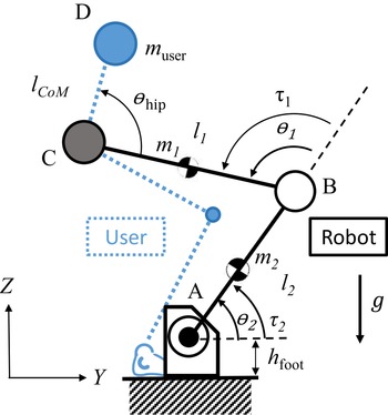

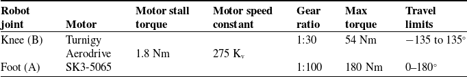


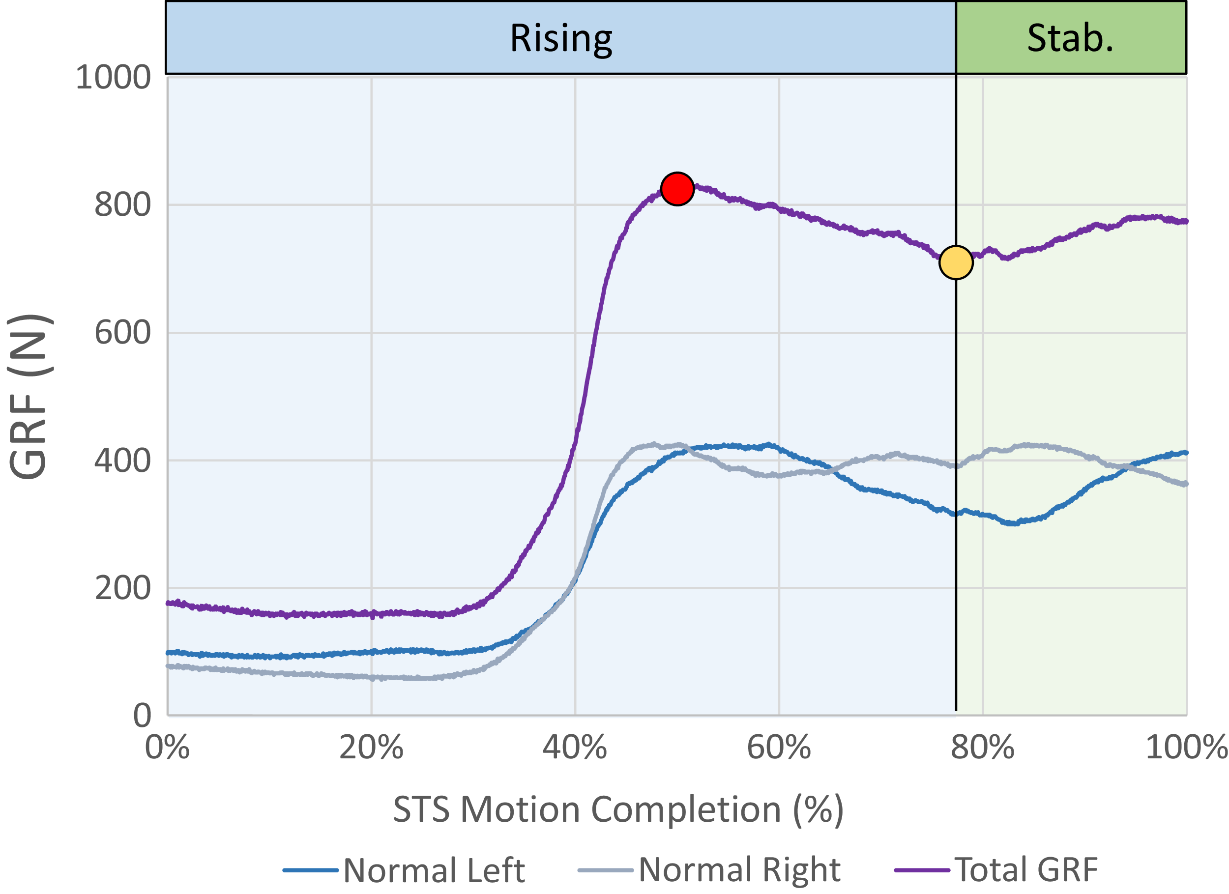


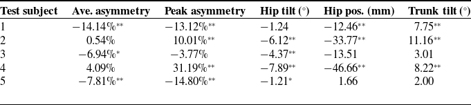
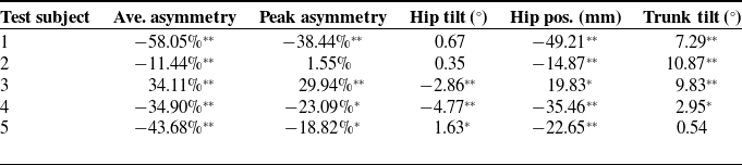

 Open access