


1. Introduction
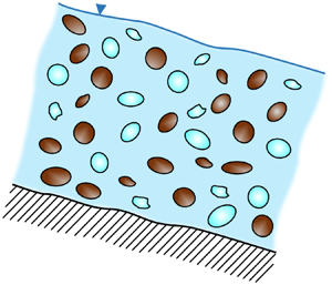
Nowadays, climate change affects most glacial environments, since the rise in temperatures is considered to be the main cause of permafrost thawing. Glaciated areas can respond to the increase in temperatures by detaching large volumes of rock and ice (Huggel Reference Huggel2009; Mergili et al. Reference Mergili, Jaboyedoff, Pullarello and Pudasaini2020a,Reference Mergili, Pudasaini, Emmer, Fischer, Cochachin and Freyb), thus possibly developing rock–ice avalanches, free-surface liquid–granular flows composed of rock, ice and a liquid. It is reasonable to consider the liquid as consisting of water with small dispersed particles, and, depending on both the type (silt or clay) and the concentration of these particles, its rheology can be Newtonian or non-Newtonian, respectively (Armanini Reference Armanini2013; Armanini et al. Reference Armanini, Larcher, Nucci and Dumbser2014). The presence of ice inside the mixture distinguishes this type of flow from other liquid–granular flows, such as debris flow (Pudasaini & Krautblatter Reference Pudasaini and Krautblatter2014). The heat produced by basal friction and collisions between solid particles induces, indeed, the transformation of ice into water, thus continuously increasing the amount of water inside the mixture. The increasing water content reduces the shear resistance of the flowing material thanks to the processes of lubrication and of fluidization (Schneider et al. Reference Schneider, Huggel, Haeberli and Kaitna2011; Pudasaini & Krautblatter Reference Pudasaini and Krautblatter2014). As a consequence, the melting process can explain both the gradual transformation of rock–ice avalanches from an essentially dry granular flow into a debris flow (Huggel et al. Reference Huggel, Zgraggen-Oswald, Haeberli, Kääb, Polkvoj, Galushkin and Evans2005; Evans & Delaney Reference Evans and Delaney2015) and the high mobility of these flows (Pudasaini & Krautblatter Reference Pudasaini and Krautblatter2014).
Although rock–ice avalanches often occur in remote areas, they need to be considered potentially dangerous to populations living at high altitudes (Evans & Delaney Reference Evans and Delaney2015). These flows can cause damage and casualties, as observed in many events throughout the world, such as the rock–ice avalanches detached from Huascaran (Peru, 1962 and 1970), from the Kolka glacier (Caucasus, 2002) and from Piz Cengalo (Switzerland, 2017) (Haeberli et al. Reference Haeberli, Huggel, Kääb, Zgraggen-Oswald, Polkvoj, Galushkin, Zotikov and Osokin2004; Petrakov et al. Reference Petrakov, Chernomorets, Evans and Tutubalina2008; Evans et al. Reference Evans, Bishop, Smoll, Murillo, Delaney and Oliver-Smith2009a,Reference Evans, Tutubalina, Drobyshev, Chernomorets, McDougall, Petrakov and Hungrb; Bartelt et al. Reference Bartelt, Christen, Bühler and Buser2018; Mergili et al. Reference Mergili, Jaboyedoff, Pullarello and Pudasaini2020a). Due to their high potential hazard and their link with climate change, rock–ice avalanches require increasing attention from the scientific community.
One of the key elements for a good hazard assessment and management consists in the capability to model rock–ice avalanches from a mathematical and a numerical point of view. Considering the main features of this type of flow, the mathematical modelling should consider the mechanical description of a multiphase solid–liquid mixture and the thermodynamics of the melting process. Therefore, the differential equations should consider the mass, momentum and energy balance laws. In the literature, mathematical models for rock–ice avalanches are rather sparse. To the best of our knowledge, the first studies of this type of flows correspond to the applicative works of Evans et al. (Reference Evans, Tutubalina, Drobyshev, Chernomorets, McDougall, Petrakov and Hungr2009b) and Schneider et al. (Reference Schneider, Bartelt, Caplan-Auerbach, Christen, Huggel and McArdell2010), two studies based on the use of the mathematical models for rapid landslides and snow avalanches developed by McDougall (Reference McDougall2006), Hungr & McDougall (Reference Hungr and McDougall2009) and Christen, Kowalski & Bartelt (Reference Christen, Kowalski and Bartelt2010). Since these approaches treat the mixture as a homogeneous monophase fluid, they are based on extremely strong assumptions that we will discuss further. In addition to these works, two different mathematical models derived specifically for rock–ice avalanches are present in the literature. On the one hand, there is the two-phase model proposed by Pudasaini & Krautblatter (Reference Pudasaini and Krautblatter2014), where the mixture is composed of a liquid component and a sole solid component (rock plus ice). To take account of the melting process, the authors introduced mass and momentum transfers between the components and these exchanges relate to the heat produced by basal friction by a specific algebraic mechanical relation (Sosio et al. Reference Sosio, Crosta, Chen and Hungr2012). In addition, the authors modelled for the first time the processes of basal lubrication and internal fluidization by making the shear resistance and the solid pressure dependent on the amount of rock and ice available inside the mixture. In this way, they were able to model the reduction in the internal and basal strength of the mixture induced by the melting process. On the other hand, there is the model proposed by Bartelt et al. (Reference Bartelt, Christen, Bühler and Buser2018), in which the flow consists of a core containing rock, ice and a liquid and of a suspended layer characterized by a dust of snow, ice and rock. Since we do not deal with the development of a suspended layer, the part of this model more relevant to our work corresponds to the core layer. More precisely, the avalanche core is modelled considering that the three distinct constituents propagate downslope with the same velocity. Moreover, the mass exchanges are linked to the mixture temperature, which is estimated by using the energy balance law written in a differential form. It is worth noting that both models of Pudasaini & Krautblatter (Reference Pudasaini and Krautblatter2014) and Bartelt et al. (Reference Bartelt, Christen, Bühler and Buser2018) are based on different assumptions, whose details will be provided further in the paper. As can be concluded from this quick literature review, the mathematical description of rock–ice avalanches is not so wide, and the existing models have quite different levels of complexity. Moreover, an explicit linkage between the different models and a definition of the limit of validity of their approximations is worth investigating.
The aim of this work is twofold. The first purpose consists of providing a general mathematical framework in which different classes of models are systematically derived and catalogued on the basis of specific assumptions. The methodology used to reach this goal is similar to that adopted by Garegnani, Rosatti & Bonaventura (Reference Garegnani, Rosatti and Bonaventura2011, Reference Garegnani, Rosatti and Bonaventura2013): start from a ‘complete’ model, and then identify the basic hypotheses to be introduced to obtain a simplified model that is consistent with the starting one. In this work, the ‘complete’ model is constructed focusing the attention on the dynamical description of the flow and neglecting the energy balance law in its differential form. In agreement with Pudasaini & Krautblatter (Reference Pudasaini and Krautblatter2014), the melting process is modelled in terms of mass and momentum transfers that are related to the heat produced by basal friction thanks to an algebraic mechanical closure relation. Moreover, the changes over time and space in the temperatures of the different components of the mixture are neglected. For more details on this description, we refer the reader to the works of Sosio et al. (Reference Sosio, Crosta, Chen and Hungr2012) and Pudasaini & Krautblatter (Reference Pudasaini and Krautblatter2014). With regard to lubrication and fluidization, we do not consider these effects, which are discussed in the work of Pudasaini & Krautblatter (Reference Pudasaini and Krautblatter2014). Being aware that neglecting both the changes in the temperature and specific models for the lubrication and fluidization effects simplifies the description of the physics of rock–ice avalanches, an even more complete approach is left to future studies. From this ‘complete’ approach, by adopting the procedure described above, five different classes of models for rock–ice avalanches can be obtained thanks to reasonable (even if in some cases drastic) simplifications. Inside each class, the models are characterized by the same number of basic differential equations, but differ from each other in the closure relations. In this way, this analysis makes it possible, firstly, to identify the physical consequences of the simplifications on the flow description, secondly, to derive a rock–ice avalanche model that can be considered a reasonable trade-off between simplicity and completeness, and lastly, to classify the existing models with the aim to understand if they can be traced back to a common ‘mother’ approach. As a result of this analysis, the model derived in this paper turns out to be representative of a new class of mathematical models for rock–ice avalanches.
The second purpose of this work consists in characterizing each class of models in terms of eigenvalues. This analysis is particularly important since it gives an insight into the mathematical nature of each class of models and provides useful information to derive (or apply) suitable numerical schemes. Moreover, the eigenvalues can also be used to define the range of applicability of a model class compared with that from which it is derived (Garegnani et al. Reference Garegnani, Rosatti and Bonaventura2011, Reference Garegnani, Rosatti and Bonaventura2013).
To avoid misunderstandings, in the following the liquid in rock–ice avalanches is considered to be water with low concentrations of silty particles, and thus it can be treated as water. Moreover, we name as ‘phase’ the mixture component characterized by given physical and mechanical properties, while as ‘state’ the matter in which each component appears in the flow (solid or liquid). Although ice represents the solid state of water from the chemical point of view, we treat water and ice as different components of the mixture and, thus, as distinct phases. Moreover, these two phases are characterized by different states: liquid for water and solid for ice. In this view, since the melting process produces a change in the phase of ice, we identify this process with the term ‘phase transformation’. In this way, rock–ice avalanches are three-phase mixtures, where a phase transformation occurs within the flow. To conclude the nomenclature used in this work, we use the acronym RIW (rock, ice and water) to refer both to the rock–ice avalanche mixture and to the three-phase model that describes its flow.
The structure of the paper is as follows. In § 2, we provide a summary of the derivation of the system of partial differential equations (PDEs) for a generic three-phase solid–liquid flow in a three-dimensional (3-D) reference system, with the aim to provide the mathematical basis useful for understanding the hypotheses underlying the subsequent steps. In § 3, we introduce the main assumptions that characterize RIW mixtures, and the general PDE system is tailored accordingly, thus leading to the basic RIW model. In § 4, a systematic procedure for deriving simplified RIW models is presented and applied. Literature models are then analysed in the context of the proposed framework to highlight whether or not they can be considered as simplified RIW models. In § 5, we present a summary of the derivation of the one-dimensional (1-D) depth-integrated versions of the simplified RIW models and, we outline the closure relations existing in the literature and used in this work. Finally, in § 6 we perform a systematic analysis of the eigenvalues for these versions of the models. Conclusions end the paper.
2. Balance equations for a generic three-phase solid–liquid flow
In the literature, there are many works that derive the equations for both two-phase and multiphase flows (Drew Reference Drew1983; Morland Reference Morland1992; Jackson Reference Jackson2000; Ishii & Hibiki Reference Ishii and Hibiki2006; Hérard Reference Hérard2007; Kolev Reference Kolev2007; Müller, Hantke & Richter Reference Müller, Hantke and Richter2016; Hérard, Hurisse & Quibel Reference Hérard, Hurisse and Quibel2021), but only in a few cases these systems of equations have been specialized for three-phase geophysical flows consisting of two solid phases and a liquid phase. To the best of our knowledge, the only mathematical model for three-phase solid–liquid mixtures, that considers three distinct field velocities, corresponds to that proposed by Pudasaini & Mergili (Reference Pudasaini and Mergili2019). This model extends the two-phase approach derived by Pudasaini (Reference Pudasaini2012) and simulates the motion of debris flows composed of a solid phase (coarse material), a fine-solid phase (e.g. sand) and a liquid phase (water and suspended particles). As a debris-flow model, no phase change occurs within the mixture and thus, no mass and momentum transfers associated with the melting process appear inside the equation system.
As specified in the introduction, rock–ice avalanches are characterized by some features that distinguish them from debris flows and these features have specific implications on the mathematical modelling. More precisely, as shown in Pudasaini & Krautblatter (Reference Pudasaini and Krautblatter2014), rock–ice avalanche models need to consider mass and momentum transfers associated with the melting process. Moreover, rock and ice have a different nature and their specific physical properties lead to a different mechanical behaviour. As a consequence, the difference in the nature of the two solid phases needs to be considered inside the intraphase and interphase stresses. Another particular feature of rock–ice avalanches concerns the fact that water and ice have very similar densities. As shown further on in the paper, this aspect has consequences on the way the interactions between these two phases are described.
Therefore, in order to derive a model specifically tailored for rock–ice avalanches, firstly, in this section we provide a summary of the continuum mechanics theory for a generic three-phase solid–liquid flow derived by extending the two-phase approach of Drew (Reference Drew1983). Then, in the next section, we will adapt this general model to the specific case by introducing suitable assumptions that lead to the RIW model. It is worth noting that this is not the only strategy to build a three-phase rock–ice avalanche model. Another possible approach may be derived by combining the three-phase model proposed by Pudasaini & Mergili (Reference Pudasaini and Mergili2019) with that in Pudasaini & Krautblatter (Reference Pudasaini and Krautblatter2014). Some of the differences between our approach and the models of Pudasaini & Mergili (Reference Pudasaini and Mergili2019) and Pudasaini & Krautblatter (Reference Pudasaini and Krautblatter2014) will be highlighted in the next sections.
2.1. Overview of the microscopic and macroscopic descriptions
As in the two-phase case, three-phase mixtures can also be described as flows composed of regions occupied by single phases separated from each other by mobile surfaces. This description, commonly defined as ‘microscopic’ or discrete, characterizes the flow inside each region and the motion of each interface. The balance principles inside a region are obtained by applying the conservation equations to an infinitesimal control volume that is fully contained in the phase. Conversely, the equations valid across an interface, namely a surface that separates a given phase from another one, are obtained from an infinitesimal control volume that straddles the interface itself (Ishii & Hibiki Reference Ishii and Hibiki2006). These equations are called jump conditions. This approach can be used when the number of interfaces is limited, but in the case of a large number of interfaces (as in the case we are interested in), its application presents overwhelming difficulties.
The approach can be simplified by describing the flow of each phase at the macroscopic level. This description, also called the ‘multiphase continuum approach’, has the ability to filter the details of the flow, thus maintaining only its essential aspects. It can be derived by applying, to the microscopic equations, suitable averages that satisfy specific properties, as specified by Drew (Reference Drew1983). Time, space and ensemble averages are commonly employed by many authors (Anderson & Jackson Reference Anderson and Jackson1967; Drew & Segel Reference Drew and Segel1971; Morland Reference Morland1992; Ishii & Hibiki Reference Ishii and Hibiki2006). As a consequence, the averaging procedure leads to a formal coexistence of all the phases in any point of the field. With respect to the original equations, these macroscopic balances contain some new terms that arise as a contribution of the interfaces to the average. Conversely, with reference to the jump conditions, the averaging procedure leads to relations, called transfer conditions, that are formally equivalent to the original ones.
With regard to the mathematical symbolism used in this work, while in the microscopic description the instantaneous and local variables are denoted by the prime symbol, in the macroscopic description the averaged variables are not denoted by any superscript. In addition, the subscript  $k$, with $k=1,2,3$, is used to identify one of the different phases that compose the mixture, while the double subscript $kj$ identifies quantities related to the interfaces between the phases $k$ and $j$. Unless otherwise indicated, the double subscript holds $\forall (k,j)$ with $k,j\in \lbrack 1, 2, 3]$ and $k\neq j$. Finally, the dependence on space and time of the functions will not be explicitly indicated.
2.2. Microscopic description
The equations of the microscopic description of a three-phase mixture are reported hereafter. While the equations valid inside a phase are formulated in the same way as in the two-phase case, more attention must be paid to the jump conditions. In fact, in three-phase solid–liquid mixtures the interfaces are not of one type but of two types, according to the state of the phases that they separate. More precisely, the interfaces can be defined ‘solid–solid’ if they separate two distinct solid phases and ‘solid–liquid’ if they separate a solid phase from the liquid one. This aspect requires a more detailed treatment of the jump conditions with respect to the two-phase solid–liquid case.
2.2.1. Equations valid inside each phase
The mass and momentum PDEs valid inside each region of the  $k$th phase (Truesdell & Toupin Reference Truesdell and Toupin1960) are
 \begin{equation} \left. \begin{gathered}
\dfrac{\partial}{\partial
t}\rho_{k}^{\prime}+\boldsymbol{\nabla\cdot}
(\rho_{k}^{\prime}\boldsymbol{v}_{k}^{\prime})=0 \\
\dfrac{\partial}{\partial
t}(\rho_{k}^{\prime}\boldsymbol{v}_{k}^{\prime
})+\boldsymbol{\nabla\cdot}(\rho_{k}^{\prime}\boldsymbol{v}_{k}^{\prime
}\otimes\boldsymbol{v}_{k}^{\prime})=\boldsymbol{\nabla\cdot}{\boldsymbol{\mathsf{T}}}_{k}
^{\prime}+\rho_{k}^{\prime}\boldsymbol{g}
\end{gathered} \right\},\end{equation}
\begin{equation} \left. \begin{gathered}
\dfrac{\partial}{\partial
t}\rho_{k}^{\prime}+\boldsymbol{\nabla\cdot}
(\rho_{k}^{\prime}\boldsymbol{v}_{k}^{\prime})=0 \\
\dfrac{\partial}{\partial
t}(\rho_{k}^{\prime}\boldsymbol{v}_{k}^{\prime
})+\boldsymbol{\nabla\cdot}(\rho_{k}^{\prime}\boldsymbol{v}_{k}^{\prime
}\otimes\boldsymbol{v}_{k}^{\prime})=\boldsymbol{\nabla\cdot}{\boldsymbol{\mathsf{T}}}_{k}
^{\prime}+\rho_{k}^{\prime}\boldsymbol{g}
\end{gathered} \right\},\end{equation}
where  $\rho _{k}^{\prime },\boldsymbol {v}_{k}^{\prime }$ and ${\boldsymbol{\mathsf{T}}}_{k} ^{\prime }$ are, respectively, the density, velocity and stress tensor related to the $k$th phase, while $\boldsymbol {g}$ is the gravity vector.
2.2.2. Jump conditions
According to Ishii & Hibiki (Reference Ishii and Hibiki2006), the mass jump condition valid between phase  $k$ and phase $j$ reads
 \begin{equation} {-}\rho_{k}^{\prime}(\boldsymbol{v}_{k}^{\prime}-\boldsymbol{v}_{kj}^{\prime })\boldsymbol{\cdot}\boldsymbol{N}_{kj}+\rho_{j}^{\prime}(\boldsymbol{v} _{j}^{\prime}-\boldsymbol{v}_{kj}^{\prime})\boldsymbol{\cdot}\boldsymbol{N} _{kj}=0 ,\end{equation}
where  $\boldsymbol {v}_{kj}^{\prime }$ represents the velocity vector of the interface separating phase $k$ from phase $j$, while $\boldsymbol {N}_{kj}$ identifies the normal unit vector in a point of this interface, pointing outside phase $k$ towards phase $j$. Each term expresses a mass flux that is associated with a phase transformation.
The momentum jump condition (Ishii & Hibiki Reference Ishii and Hibiki2006) is defined as follows:
where  $\sigma ^{\prime }$ and ${K}$ represent the surface tension and the surface curvature, respectively. There appear two different contributions: one referred to the momentum flux associated with the mass exchange and the other related to the stresses exerted by the two phases on the interface.
2.3. Macroscopic description
The macroscopic equations reported hereafter are derived by considering, as a reference average operator, a spherical volume  $\mathcal {V}$ with a radius larger than the solid particles. In this description, the fraction of reference volume occupied by the generic phase $k$ is defined by $\alpha _k$. Since all the space occupied by the mixture is completely filled by the phases, the following equality holds:
 \begin{equation} \sum_{k=1}^{3}\alpha_{k}=1. \end{equation}
2.3.1. Gradients of the volume fractions
Following Drew (Reference Drew1983), the gradient of a volume fraction represents the oriented surface (per unit volume) that arises by averaging the local contact areas of a phase with the others (see Appendix A). With reference to the liquid phase, here identified by the subscript  $k=3$, the quantity $\boldsymbol {\nabla }\alpha _3$ identifies the oriented average interfacial surface that separates the liquid phase from the two solid phases. Thus, it can be split into two terms
 \begin{equation} \boldsymbol{\nabla}\alpha_3=[\boldsymbol{\nabla}\alpha_3]_1+ [\boldsymbol{\nabla}\alpha_3]_2,\end{equation}
where  $[\boldsymbol {\nabla }\alpha _3]_k$ with $k=1, 2$ represents the contribution relevant to each solid phase. With regard to the gradients of the two solid phases, the corresponding oriented average interfacial surfaces need to take account of both the solid–liquid and solid–solid contact areas. In this way, they can be expressed as follows:
 $$\begin{gather} \boldsymbol{\nabla}\alpha_1=[\boldsymbol{\nabla}\alpha_1]_3+ [\boldsymbol{\nabla}\alpha_1]_2, \end{gather}$$
 $$\begin{gather}\boldsymbol{\nabla}\alpha_2=[\boldsymbol{\nabla}\alpha_2]_3+ [\boldsymbol{\nabla}\alpha_2]_1, \end{gather}$$
where  $[\boldsymbol {\nabla }\alpha _k]_3$ with $k=1, 2$ represents the oriented average interfacial surface that separates the solid phase $k$ from the liquid one, while $[\boldsymbol {\nabla }\alpha _1]_2$ and $[\boldsymbol {\nabla }\alpha _2]_1$ correspond to the oriented average interfacial surfaces separating the two solid phases.
Considering that, in a point of an interface, the surface that separates two phases is unique, the oriented surfaces relevant to these phases are vectors equal in absolute value and opposite in direction. This relation holds also in terms of averaged variables (see Appendix A) and, therefore, the following equalities hold:
 \begin{gather}
{[}\boldsymbol{\nabla}\alpha_3]_k={-}[\boldsymbol{\nabla}\alpha_k]_3
\quad\text{with }k=1, 2,
\end{gather}
\begin{gather}
{[}\boldsymbol{\nabla}\alpha_3]_k={-}[\boldsymbol{\nabla}\alpha_k]_3
\quad\text{with }k=1, 2,
\end{gather}
 \begin{gather}{[}\boldsymbol{\nabla}\alpha_2]_1={-}[\boldsymbol{\nabla}\alpha_1]_2.
\end{gather}
\begin{gather}{[}\boldsymbol{\nabla}\alpha_2]_1={-}[\boldsymbol{\nabla}\alpha_1]_2.
\end{gather}
The quantity  $\boldsymbol {\nabla }\alpha _3$ can be linked to the gradients of the volume fraction of the other phases by applying the gradient operator to (2.4), thus obtaining the following equation:
 \begin{equation} \boldsymbol{\nabla}\alpha_3={-}\boldsymbol{\nabla}\alpha_1- \boldsymbol{\nabla}\alpha_2.\end{equation}
It is worth noting that adding (2.6a) to (2.6b) and applying (2.7) and (2.8) to the resulting equation, it is possible to derive an equation that coincides with (2.9).
Finally, assuming that the averaged contact area between the two solid phases is much smaller than the averaged surface between a solid phase and the liquid one, the relation (2.6) can be simplified as follows:
 \begin{equation} \boldsymbol{\nabla}\alpha_k\simeq[\boldsymbol{\nabla}\alpha_k]_3 \quad\text{with } k=1, 2.\end{equation}
It is worthy of note that this assumption may not occur in all situations, such as when the liquid concentrations are low and the mixture behaves like a solid (Takahashi Reference Takahashi2007; Schneider et al. Reference Schneider, Huggel, Haeberli and Kaitna2011; Andreotti, Forterre & Pouliquen Reference Andreotti, Forterre and Pouliquen2013; Pudasaini & Krautblatter Reference Pudasaini and Krautblatter2014). For more details on the mathematical proof of (2.5)–(2.10), we refer the reader to Appendix A.
2.3.2. Mass balance equations
The averaged mass balance equation for the  $k$th phase can be derived from the first equation of system (2.1) and reads
 \begin{equation} \frac{\partial}{\partial t}( \alpha_{k}\rho_{k}) +\boldsymbol{\nabla\cdot}( \alpha_{k}\rho_{k}\boldsymbol{u}_{k}) =\varGamma_{k}, \end{equation}
where  $\rho _{k}$ and $\boldsymbol {u}_{k}$ indicate the averaged density and velocity of the $k$th phase, respectively, while $\varGamma _{k}$ expresses the global mass transfer (per unit volume) between the $k$th phase and all the other components of the mixture. It can be subdivided as
 \begin{equation} \varGamma_{k}=\sum_{j=1}^{3}(1-\delta_{kj})\varGamma_{kj},\end{equation}
where  $\delta _{kj}$ identifies the Kronecker delta function and allows us to delete the meaningless term $\varGamma _{kk}$. We define $\varGamma _{kj}$ as positive whether the transfer of mass occurs from phase $j$ to phase $k$. Since it cannot be written automatically in terms of averaged variables, a proper closure relation needs to be provided.
2.3.3. Momentum balance equations
The momentum balance equation for the  $k$th phase can be derived from the second equation of system (2.1) and reads
 \begin{equation} \frac{\partial}{\partial t}( \alpha_{k}\rho_{k}\boldsymbol{u} _{k}) +\boldsymbol{\nabla\cdot}( \alpha_{k}\rho_{k} \boldsymbol{u}_{k}\otimes\boldsymbol{u}_{k}) =\boldsymbol{\nabla\cdot }( \alpha_{k}{\boldsymbol{\mathsf{T}}}_{k}) +\alpha_{k}\rho_{k} \boldsymbol{g} +\boldsymbol{M}_{k}.\end{equation}
In this equation,  ${\boldsymbol{\mathsf{T}}}_{k}$ is the average intraphase tensor that is viscous in the case of a fluid phase and frictional/collisional in the case of a solid phase. In both cases, proper closure relations need to be introduced for this term. In addition, in (2.13) $\boldsymbol {M}_{k}$ is the resultant of the interphase stresses exerted on the $k$th phase by the other components of the mixture
 \begin{equation} \boldsymbol{M}_{k}=\sum_{j=1}^{3}(1-\delta_{kj})\boldsymbol{M}_{kj}.\end{equation}
 Due to the presence of solid–solid and solid–liquid interfaces, the interphase stress  $\boldsymbol {M}_{kj}$ needs to be specified according to the type of interfaces that separate the phases $k$ and $j$.
$j$.
Solid–liquid interphase stress. In agreement with Drew (Reference Drew1983), Jackson (Reference Jackson2000) and Ishii & Hibiki (Reference Ishii and Hibiki2006), the solid–liquid interphase stress can be split into a momentum transfer and into static and dynamic stresses exerted on the interfaces,
 \begin{equation} \boldsymbol{M}_{kj}=\varGamma_{kj}\boldsymbol{u}_{kj}- [\boldsymbol{\nabla}\alpha_{k}]_{j}\boldsymbol{\cdot} {\boldsymbol{\mathsf{T}}}_{kj}+\boldsymbol{M}_{kj}^{D}.\end{equation}
On the right-hand side of (2.15), the first term, namely  $\varGamma _{kj}\boldsymbol {u}_{kj}$, identifies the momentum transfer between phase $k$ and phase $j$. The variable $\boldsymbol {u}_{kj}$ represents the averaged interfacial velocity and needs to be defined by proper (constitutive) assumptions. The second term namely $-[\boldsymbol {\nabla }\alpha _{k}]_{j}\boldsymbol {\cdot }{\boldsymbol{\mathsf{T}}}_{kj}$, represents the static contribution of the averaged stress exerted at the interfaces by phase $j$ on phase $k$. The third term, namely $\boldsymbol {M}_{kj}^{D}$, identifies the dynamic contribution of the averaged stress exerted on the interfaces and it arises from the relative motion of the solid and liquid phases. It takes account of the effects of drag, virtual mass and lift (Ishii & Hibiki Reference Ishii and Hibiki2006). For brevity, in the following we call this term as the drag stress.
Both  ${\boldsymbol{\mathsf{T}}}_{kj}$ and $\boldsymbol {M}_{kj}^{D}$ need to be specified by proper closure relations.
Finally, thanks to (2.10) and to (2.7), the solid–liquid interphase stresses can be rewritten as follows:
 \begin{equation}
\boldsymbol{M}_{kj}=\left\{ \begin{array}{@{}ll}
\varGamma_{kj}\boldsymbol{u}_{kj}-\boldsymbol{\nabla}\alpha_{k}\boldsymbol{\cdot
}{\boldsymbol{\mathsf{T}}}_{kj}+\boldsymbol{M}_{kj}^{D}
& \text{if } k \text{ identifies a solid phase},\\
\varGamma_{kj}\boldsymbol{u}_{kj}+\boldsymbol{\nabla}\alpha_{j}\boldsymbol{\cdot
}{\boldsymbol{\mathsf{T}}}_{kj}+\boldsymbol{M}_{kj}^{D}
& \text{if }k \text{ identifies the liquid phase}.\end{array} \right.
\end{equation}
\begin{equation}
\boldsymbol{M}_{kj}=\left\{ \begin{array}{@{}ll}
\varGamma_{kj}\boldsymbol{u}_{kj}-\boldsymbol{\nabla}\alpha_{k}\boldsymbol{\cdot
}{\boldsymbol{\mathsf{T}}}_{kj}+\boldsymbol{M}_{kj}^{D}
& \text{if } k \text{ identifies a solid phase},\\
\varGamma_{kj}\boldsymbol{u}_{kj}+\boldsymbol{\nabla}\alpha_{j}\boldsymbol{\cdot
}{\boldsymbol{\mathsf{T}}}_{kj}+\boldsymbol{M}_{kj}^{D}
& \text{if }k \text{ identifies the liquid phase}.\end{array} \right.
\end{equation}
Solid–solid interphase stress. Similarly to the solid–liquid case, the interphase stress can be split into a momentum transfer and an averaged stress exerted on the interfaces. Conversely, while the splitting of the averaged stress into a static and a dynamic effect is quite accepted for dry granular flows (Gray & Thornton Reference Gray and Thornton2005; Gray & Chugunov Reference Gray and Chugunov2006; Tripathi & Khakhar Reference Tripathi and Khakhar2013; Tunuguntla, Bokhove & Thornton Reference Tunuguntla, Bokhove and Thornton2014), it does not seem to be the case for fully saturated flows. To the best of our knowledge, the only model for granular–liquid flows that considers the splitting of the solid–solid averaged stress into static and dynamic effects corresponds to the approach proposed by Pudasaini & Mergili (Reference Pudasaini and Mergili2019). However, we prefer to express this averaged stress in terms of frictional and collisional actions by analogy with the solid intraphase tensor (Jenkins & Savage Reference Jenkins and Savage1983; Armanini et al. Reference Armanini, Larcher, Nucci and Dumbser2014). We do not discuss further the differences between these two approaches, since this is outside the scope of this work, as explained further on in the paper. In this way, for the solid–solid interphase stresses we get
 \begin{equation} \boldsymbol{M}_{kj}=\varGamma_{kj}\boldsymbol{u}_{kj}+\boldsymbol{M}_{kj} ^{F}+\boldsymbol{M}_{kj}^{C}, \end{equation}
where  $\varGamma _{kj}\boldsymbol {u}_{kj}$ represents the momentum transfer; $\boldsymbol {M}_{kj}^{F}$ identifies the action due to the long-term frictional contacts between particles of different phases; $\boldsymbol {M}_{kj}^{C}$ corresponds to the action due to short-term collisions between particles of different phases.
Both  $\boldsymbol {M}_{kj}^{F}$ and $\boldsymbol {M}_{kj}^{C}$ need to be specified by proper closure relations.
2.3.4. Mass transfer conditions
The mass transfer conditions are derived averaging (2.2) and read as follows:
 \begin{equation} \varGamma_{kj}+\varGamma_{jk}=0. \end{equation}
Adding together the mass transfer conditions related to all the phases, it is possible to derive the following expression:
 \begin{equation} \sum_{k=1}^{3}\sum_{j=1}^{3}(1-\delta_{kj})\varGamma_{kj}=0, \end{equation}
which, thanks to (2.12), becomes
 \begin{equation} \sum_{k=1}^{3}\varGamma_{k}=0. \end{equation}
2.3.5. Momentum transfer conditions
The momentum transfer conditions can be specified in two ways, whether the surface tension is assumed to be relevant or not.
Presence of surface tension. The momentum transfer conditions can be expressed by
 \begin{equation} \boldsymbol{M}_{kj}+\boldsymbol{M}_{jk}=[ \sigma\kappa\boldsymbol{n} ]_{kj}, \end{equation}
where  $\kappa$ represents the averaged curvature and $\boldsymbol {n}$ the averaged normal unit vector. It is worth noting that the effect of the surface tension $\sigma$ can be considered relevant in the case of mixtures consisting of solid particles submerged in a fluid. In this situation, the surface curvature $\kappa$ can be linked to the particle diameter. These transfer conditions can be expressed by using (2.16) as follows:
 \begin{equation} (\varGamma_{kj}\boldsymbol{u}_{kj}+\varGamma_{jk}\boldsymbol{u}_{jk} )+\boldsymbol{\nabla}\alpha_{k}\boldsymbol{\cdot}({\boldsymbol{\mathsf{T}}}_{jk} -{\boldsymbol{\mathsf{T}}}_{kj})+(\boldsymbol{M}_{kj}^{D}+\boldsymbol{M}_{jk}^{D} )=[\sigma\kappa\boldsymbol{n}]_{kj}, \end{equation}
where  $k$ identifies a solid phase and $j$ the liquid phase.
Absence of surface tension. The momentum transfer conditions are expressed by
 \begin{equation} \boldsymbol{M}_{kj}+\boldsymbol{M}_{jk}=0. \end{equation}
These relations can be considered as representative of the interphase stresses between two solid phases. By using (2.17), they become
 \begin{equation} \varGamma_{kj}\boldsymbol{u}_{kj}+\boldsymbol{M}_{kj}^{F}+\boldsymbol{M}_{kj} ^{C}={-}(\varGamma_{jk}\boldsymbol{u}_{jk}+\boldsymbol{M}_{jk}^{F}+\boldsymbol{M} _{jk}^{C}). \end{equation}
3. The equations for the macroscopic RIW model
The RIW model provided in this work considers rock and ice as homogeneous phases characterized by their corresponding particle size. It is constructed starting from the equations presented in § 2 and specifying the main features that characterize this mixture. These features affect the interphase terms in (2.11) and (2.13), and the transfer conditions.
Hereafter, the subscript  $k$ is substituted by letters identifying the three different phases: $r$,
$r$,  $i$ and $w$ stand for rock, ice and water, respectively. In this way, the relation that characterizes the volumetric fractions, (2.4), becomes
 \begin{equation} \alpha_{r}+\alpha_{i}+\alpha_{w}=1. \end{equation}
3.1. Interphase terms
With regard to the mass transfers, in RIW mixtures they can occur only between ice and water. Therefore, the mass transfers related to these phases differ from zero,
 \begin{equation} \varGamma_{iw}\neq0\cup\varGamma_{wi}\neq 0, \end{equation}
while all the other terms are null. Thus, considering (2.12) we can write
 $$\begin{gather} \varGamma_{r} =\varGamma_{ri}+\varGamma_{rw}\Longrightarrow\varGamma_{r}=0, \end{gather}$$
 $$\begin{gather}\varGamma_{i} =\varGamma_{ir}+\varGamma_{iw}\Longrightarrow\varGamma_{i}=\varGamma_{iw}, \end{gather}$$
 $$\begin{gather}\varGamma_{w} =\varGamma_{wi}+\varGamma_{wr}\Longrightarrow\varGamma_{w}=\varGamma_{wi}. \end{gather}$$
With regard to the interphase stresses, we can distinguish between: (i) solid–liquid interactions that are described by (2.16) and occur between water and rock and between water and ice; and (ii) solid–solid interactions that are described by (2.17) and occur between rock and ice.
By using (3.3), these terms become
 $$\begin{gather} \boldsymbol{M}_{r}=\boldsymbol{M}_{ri}+\boldsymbol{M}_{rw}\quad \text{where } \begin{cases} \boldsymbol{M}_{ri} =\boldsymbol{M}_{ri}^{C}+\boldsymbol{M}_{ri}^{F}\\ \boldsymbol{M}_{rw} =\boldsymbol{M}_{rw}^{D}-\boldsymbol{\nabla}\alpha _{r}\boldsymbol{\cdot}{\boldsymbol{\mathsf{T}}}_{ri} \end{cases}, \end{gather}$$
 $$\begin{gather}\boldsymbol{M}_{i}=\boldsymbol{M}_{ir}+\boldsymbol{M}_{iw}\quad \text{where } \begin{cases} \boldsymbol{M}_{ir} =\boldsymbol{M}_{ir}^{C}+\boldsymbol{M}_{ir}^{F}\\ \boldsymbol{M}_{iw} =\boldsymbol{M}_{iw}^{D}-\boldsymbol{\nabla}\alpha _{i}\boldsymbol{\cdot}{\boldsymbol{\mathsf{T}}}_{iw}+\varGamma_{i}\boldsymbol{u}_{iw} \end{cases}, \end{gather}$$
 $$\begin{gather}\boldsymbol{M}_{w}=\boldsymbol{M}_{wr}+\boldsymbol{M}_{wi}\quad \text{where } \begin{cases} \boldsymbol{M}_{wr} =\boldsymbol{M}_{wr}^{D}+\boldsymbol{\nabla}\alpha _{r}\boldsymbol{\cdot}{\boldsymbol{\mathsf{T}}}_{wr}\\ \boldsymbol{M}_{wi} =\boldsymbol{M}_{wi}^{D}+\boldsymbol{\nabla}\alpha _{i}\boldsymbol{\cdot}{\boldsymbol{\mathsf{T}}}_{wi}+\varGamma_{w}\boldsymbol{u}_{wi} \end{cases}. \end{gather}$$
3.2. Transfer conditions
With reference to the mass transfer condition, the existence of only two phases that exchange mass reduces (2.18) to the following relation:
 \begin{equation} \varGamma_{wi}={-}\varGamma_{iw} ,\end{equation}
and, therefore, thanks to (3.3b) and (3.3c), it becomes
 \begin{equation} \varGamma_{w}={-}\varGamma_{i}. \end{equation}
This condition states that the two mass transfers are equal to each other in absolute value and opposite in sign. The ice melting is responsible for a loss of ice mass and for an acquisition of water mass. Therefore,  $\varGamma _{i}$ and $\varGamma _{w}$ are, respectively, negative and positive. To better highlight these features, in the following we set $\varGamma _{i}=-\vert \varGamma _{i}\vert$ and $\varGamma _{w}=+\vert \varGamma _{i}\vert$.
Concerning with the transfer conditions related to the momentum, the surface tension affects only the conditions involving water. Therefore, (2.21) and (2.23) become
 $$\begin{gather} \boldsymbol{M}_{ri}+\boldsymbol{M}_{ir}=0, \end{gather}$$
 $$\begin{gather}\boldsymbol{M}_{rw}+\boldsymbol{M}_{wr}=[\sigma\kappa\boldsymbol{n}]_{rw}, \end{gather}$$
 $$\begin{gather}\boldsymbol{M}_{iw}+\boldsymbol{M}_{wi}=[\sigma\kappa\boldsymbol{n}]_{iw}. \end{gather}$$
In accordance with (3.4), we obtain
 $$\begin{gather} \boldsymbol{M}_{ri}^{C}+\boldsymbol{M}_{ri}^{F}={-} (\boldsymbol{M}_{ir}^{C}+\boldsymbol{M}_{ir}^{F} ), \end{gather}$$
 $$\begin{gather}( \boldsymbol{M}_{wr}^{D}+\boldsymbol{\nabla}\alpha_{r}\boldsymbol{\cdot}{\boldsymbol{\mathsf{T}}}_{wr} ) +(\boldsymbol{M}_{rw}^{D}-\boldsymbol{\nabla}\alpha_{r}\boldsymbol{\cdot}{\boldsymbol{\mathsf{T}}}_{rw} )=[\sigma\kappa\boldsymbol{n}]_{rw}, \end{gather}$$
 $$\begin{gather}(\boldsymbol{M}_{wi}^{D}+\boldsymbol{\nabla}\alpha_{i}\boldsymbol{\cdot}{\boldsymbol{\mathsf{T}}}_{wi}+ \vert \varGamma_i \vert\boldsymbol{u}_{wi} ) + (\boldsymbol{M}_{iw}^{D}-\boldsymbol{\nabla}\alpha_{i} \boldsymbol{\cdot}{\boldsymbol{\mathsf{T}}}_{iw}- \vert \varGamma_i \vert\boldsymbol{u}_{iw} ) =[\sigma\kappa\boldsymbol{n}]_{iw} . \end{gather}$$
3.2.1. Assumptions affecting the transfer conditions
With regard to the transfer conditions, it is possible to introduce some reasonable assumptions that can simplify the set of equations for the RIW model.
(i) Each phase is incompressible: $\rho _{r}$, $\rho _{i}$, $\rho _{w}$ are constant in time and space.
(ii) With regard to the momentum transfer condition between rock and ice (equation (3.8a)), the action–reaction principle holds between each type of stresses,
(3.9a)$$\begin{gather} \boldsymbol{M}_{ri}^{C}={-}\boldsymbol{M}_{ir}^{C}, \end{gather}$$(3.9b)$$\begin{gather}\boldsymbol{M}_{ri}^{F}={-}\boldsymbol{M}_{ir}^{F}. \end{gather}$$(iii) With reference to the momentum transfer conditions between water and the two solid phases, the surface tension is considered negligible. This hypothesis is quite reasonable in the case of rock since these grains have generally large dimensions and their curvature is small. On the other hand, it is not always valid in the case of ice grains: while in the initial stages of the flow they are commonly large, the melting process and the fragmentation due to the collisions progressively reduce the diameter of the ice particles and increase their curvature. In this way, there is an increase in the effect of the surface tension. Nevertheless, we assume that, in any case, the surface tension has a smaller order of magnitude compared with the other stresses. Thanks to this assumption, the transfer conditions expressed by (3.8b) and (3.8c) reduce to the action–reaction principle between the resultants of the interphase stresses as follows:
(3.10a)$$\begin{gather} \boldsymbol{M}_{wr}^{D}+\boldsymbol{\nabla}\alpha_{r}\boldsymbol{\cdot}{\boldsymbol{\mathsf{T}}}_{wr} ={-} ( \boldsymbol{M}_{rw}^{D}-\boldsymbol{\nabla}\alpha_{r}\boldsymbol{\cdot} {\boldsymbol{\mathsf{T}}}_{rw} ), \end{gather}$$(3.10b)$$\begin{gather}\boldsymbol{M}_{wi}^{D}+\boldsymbol{\nabla}\alpha_{i}\boldsymbol{\cdot} {\boldsymbol{\mathsf{T}}}_{wi}+ \vert \varGamma_i \vert\boldsymbol{u}_{wi} ={-} (\boldsymbol{M}_{iw}^{D}-\boldsymbol{\nabla}\alpha_{i} \boldsymbol{\cdot}{\boldsymbol{\mathsf{T}}}_{iw}- \vert \varGamma_i \vert\boldsymbol {u}_{iw} ) . \end{gather}$$(iv) For the drag stresses, according to Drew (Reference Drew1983), we have
(3.11a)$$\begin{gather} \boldsymbol{M}_{wr}^{D}={-}\boldsymbol{M}_{rw}^{D}, \end{gather}$$(3.11b)Therefore, relations (3.10) reduce to$$\begin{gather}\boldsymbol{M}_{wi}^{D}={-}\boldsymbol{M}_{iw}^{D}. \end{gather}$$(3.12a)$$\begin{gather} \boldsymbol{\nabla}\alpha_{r}\boldsymbol{\cdot}{\boldsymbol{\mathsf{T}}}_{wr} =\boldsymbol{\nabla}\alpha_{r}\boldsymbol{\cdot} {\boldsymbol{\mathsf{T}}}_{rw}, \end{gather}$$(3.12b)$$\begin{gather}\boldsymbol{\nabla}\alpha_{i}\boldsymbol{\cdot}{\boldsymbol{\mathsf{T}}}_{wi}+\vert \varGamma_i\vert\boldsymbol{u}_{wi} =\boldsymbol{\nabla} \alpha_{i}\boldsymbol{\cdot}{\boldsymbol{\mathsf{T}}}_{iw}+\vert \varGamma_i\vert\boldsymbol{u}_{iw} . \end{gather}$$(v) The mass jump condition expressed by (2.2) suggests that, if the two phases have similar densities, the normal velocities are the same. In addition, the adherence condition implies that the tangential velocities are equal (Ishii & Hibiki Reference Ishii and Hibiki2006). By combining these two conditions, we can state that, whether the two phases have similar densities, the velocity vectors of the two phases are the same nearby the interface, namely
$\boldsymbol {v}_{k}^{\prime }=\boldsymbol {v}_{j}^{\prime }$. According to Drew (Reference Drew1983, p. 268), whether a solution is true at the microscopic level, it can be used to obtain the solution of the macroscopic problem. In this way, the equality between the microscopic velocities implies an equality between the macroscopic velocity vectors.Since the densities of ice and water are approximately the same (consider for example
$\rho _{w}=1000\ {kg}\ {m}^{-3}$ and $\rho _{i}=917\ {kg}\ {m}^{-3}$), the velocity vectors of ice and water in the momentum transfer condition (3.12b) can be supposed equal to each other. Moreover, we can assume that these two velocities coincide with an averaged value that depends on the mass transfer, namely
(3.13)This averaged velocity needs to be defined by a proper closure relation. Based on this relation, (3.12b) reduces to\begin{equation} \boldsymbol{u}_{iw}=\boldsymbol{u}_{wi}= \boldsymbol{u}_{ss}(\varGamma_{i}).\end{equation}(3.14)\begin{equation} \boldsymbol{\nabla}\alpha_{i}{\cdot}{\boldsymbol{\mathsf{T}}}_{wi}=\boldsymbol{\nabla} \alpha_{i}\boldsymbol{\cdot}{\boldsymbol{\mathsf{T}}}_{iw}.\end{equation}(vi) With regard to the stress tensors describing the actions exerted by water on rock and ice (namely
${\boldsymbol{\mathsf{T}}}_{rw}$ and ${\boldsymbol{\mathsf{T}}}_{iw}$), if we neglect the surface tension, water cannot distinguish whether it is acting on rock particles or on ice grains. Consequently, these two stress tensors are equal to each other, ${\boldsymbol{\mathsf{T}}}_{rw}={\boldsymbol{\mathsf{T}}}_{iw}$. Assuming that these actions coincide with the internal water stress tensor, the following equalities hold:
(3.15a)\begin{gather} {\boldsymbol{\mathsf{T}}}_{rw}={\boldsymbol{\mathsf{T}}}_{w}, \end{gather}(3.15b)Concerning with the actions exerted by rock and ice on water,\begin{gather}{\boldsymbol{\mathsf{T}}}_{iw}={\boldsymbol{\mathsf{T}}}_{w}. \end{gather}${\boldsymbol{\mathsf{T}}}_{wr}$ and ${\boldsymbol{\mathsf{T}}}_{wi}$, we can add together (3.12a) and (3.14), thus obtaining
(3.16)Thanks to (3.15), we can collect\begin{equation} \boldsymbol{\nabla}\alpha_{r}\boldsymbol{\cdot}{\boldsymbol{\mathsf{T}}}_{wr} +\boldsymbol{\nabla}\alpha_{i}\boldsymbol{\cdot}{\boldsymbol{\mathsf{T}}}_{wi} =\boldsymbol{\nabla}\alpha_{r}\boldsymbol{\cdot}{\boldsymbol{\mathsf{T}}}_{rw} +\boldsymbol{\nabla}\alpha_{i}\boldsymbol{\cdot}{\boldsymbol{\mathsf{T}}}_{iw}. \end{equation}${\boldsymbol{\mathsf{T}}}_{w}$ at the right-hand side. The remaining term $\boldsymbol {\nabla }\alpha _{r} +\boldsymbol {\nabla }\alpha _{i}$ results to be equal to $-\boldsymbol {\nabla }\alpha _{w}$, thanks to (3.1). In this way, it is possible to obtain the following equality:
(3.17)\begin{equation} \boldsymbol{\nabla}\alpha_{r}\boldsymbol{\cdot}{\boldsymbol{\mathsf{T}}}_{wr} +\boldsymbol{\nabla}\alpha_{i}\boldsymbol{\cdot}{\boldsymbol{\mathsf{T}}}_{wi} ={-}\boldsymbol{\nabla}\alpha_{w}\boldsymbol{\cdot}{\boldsymbol{\mathsf{T}}}_{w}.\end{equation}


3.3. The final set
Introducing all the assumptions specified in the previous section, the final set of equations for the RIW model is composed of the macroscopic mass and momentum balance laws related to each phase (namely (2.11) and (2.13)), and of the basic relation (3.1). The system reads
 \begin{gather} \frac{\partial}{\partial t} ( \alpha_{{r}}\rho_{{r}} ) +\boldsymbol{\nabla\cdot} ( \alpha_{{r}}\rho_{{r}}\boldsymbol{u}_{{r} } ) = 0, \end{gather}
 \begin{gather} \frac{\partial}{\partial t} ( \alpha_{{i}}\rho_{{i}} ) +\boldsymbol{\nabla\cdot} ( \alpha_{{i}}\rho_{{i}}\boldsymbol{u}_{{i} } ) ={-} \vert \varGamma_{{i}} \vert, \end{gather}
 \begin{gather}\frac{\partial}{\partial t} ( \alpha_{{w}}\rho_{{w}} ) +\boldsymbol{\nabla\cdot} ( \alpha_{{w}}\rho_{{w}}\boldsymbol{u}_{{w} } ) ={+} \vert \varGamma_{{i}} \vert, \end{gather}
 \begin{gather} \frac{\partial}{\partial t} ( \alpha_{{r}}\rho_{{r}}\boldsymbol{u}_{{r}} ) +\boldsymbol{\nabla\cdot} (\alpha_{{r}}\rho_{{r}}\boldsymbol{u}_{{r}}\otimes\boldsymbol{u}_{{r}} ) ={-}\boldsymbol{\nabla\cdot} ( \alpha_{{r}}{\boldsymbol{\mathsf{T}}}_{{r}} ) +\alpha_{{r}}\rho_{{r}}\boldsymbol{g}+\boldsymbol{\nabla}\alpha_{{r}} \boldsymbol{\cdot}{\boldsymbol{\mathsf{T}}}_{{w}}\nonumber\\ \hspace{8.3pc}\qquad\quad +\, \boldsymbol{M}_{{rw}}^{D}+\boldsymbol{M}_{{ri}}^{C}+\boldsymbol{M}_{{ri}}^{F}, \end{gather}
 \begin{gather} \frac{\partial}{\partial t} ( \alpha_{{i}}\rho_{{i}}\boldsymbol{u}_{{i}} ) +\boldsymbol{\nabla\cdot} ( \alpha_{{i}}\rho_{{i}}\boldsymbol{u}_{{i}}\otimes\boldsymbol{u}_{{i}} ) ={-}\boldsymbol{\nabla\cdot} ( \alpha_{{i}}{\boldsymbol{\mathsf{T}}}_{{i}} ) +\alpha_{{i}}\rho_{{i}}\boldsymbol{g}- \vert \varGamma_{{i}} \vert \boldsymbol{u}_{ss}+\boldsymbol{\nabla}\alpha_{{i}}\boldsymbol{\cdot}{\boldsymbol{\mathsf{T}}}_{{w}}\nonumber\\ \qquad\hspace{4.5pc}\,\, +\,\boldsymbol{M}_{{iw}}^{D}-\boldsymbol{M}_{{ri}}^{C}-\boldsymbol{M}_{{ri}}^{F}, \end{gather}
 \begin{gather} \frac{\partial}{\partial t} ( \alpha_{{w}}\rho_{{w}}\boldsymbol{u}_{{w}} ) +\boldsymbol{\nabla\cdot} ( \alpha_{{w}}\rho_{{w}}\boldsymbol{u}_{{w}}\otimes\boldsymbol{u}_{{w}} ) ={-}\boldsymbol{\nabla\cdot} (\alpha_{{w}}{\boldsymbol{\mathsf{T}}}_{{w}} )+\alpha_{{w}}\rho_{{w}}\boldsymbol{g}+ \vert \varGamma_{i} \vert \boldsymbol{u}_{{ss}}\nonumber\\ \hspace{14.5pc}+\boldsymbol{\nabla}\alpha_{{w}}\boldsymbol{\cdot} {\boldsymbol{\mathsf{T}}}_{{w}}-\boldsymbol{M}_{{iw}}^{D}-\boldsymbol{M}_{rw}^{D}, \end{gather}
 \begin{gather} \alpha_{r}+\alpha_{i}+\alpha_{w} =1, \end{gather}
where the first three equations represent the mass balance equations related to rock, ice and water, respectively, while the next three equations identify the momentum balance equations for the three different phases (rock, ice and water, respectively). On the right-hand side of the mass and momentum balance equations  $\pm \vert \varGamma _i\vert$ and $\pm \vert \varGamma _i\vert \boldsymbol {u}_{ss}$ correspond, respectively, to the mass and momentum transfers associated with the ice melting process; $\boldsymbol {\nabla \cdot }( \alpha _{{k}}{\boldsymbol{\mathsf{T}}}_{{k}})$ (with $k=r, i\,\text {and}\,w$) represents the internal stress term related to each phase; $\alpha _{{k}}\rho _{{k}}\boldsymbol {g}$ (with $k=r, i \text { and }w$) identifies the weight term; $\boldsymbol {\nabla }\alpha _{{k}}\boldsymbol {\cdot }{\boldsymbol{\mathsf{T}}}_{{w}}$ (with $k=r, i \text { and } w$) represents the static contribution of the solid–liquid interaction stress and corresponds to the buoyancy; $\boldsymbol {M}_{kw}^D$ (with $k=r\text { and }i$) takes account of the drag stress (drag, lift and virtual mass); $\boldsymbol {M}_{ri}^C$ and $\boldsymbol {M}_{ri}^F$ express the collisional and frictional stresses that arise from the contact between rock and ice.
It is worthy of note that the stress tensors of the three-phases in (3.18d)–(3.18f) have been multiplied by  $-1$ to make positive the compressive stresses (Savage & Hutter Reference Savage and Hutter1989; Iverson & Denlinger Reference Iverson and Denlinger2001).
This system is composed of thirteen scalar equations and describes the flow in terms of thirteen unknowns. Twelve of them are present in the equations in an explicit way and correspond to the three phase concentrations  $\alpha _{r},\alpha _{i},\alpha _{w}$ and the nine scalar velocity components of $\boldsymbol {u}_{{r}},\boldsymbol {u}_{{i}},\boldsymbol {u}_{{w}}$. The last unknown is the water pressure $p_{w}$, the scalar quantity that represents the isotropic part of the water stress tensor. All the other terms in the system must be referred to these thirteen unknowns through suitable closure relations (algebraic or differential).
It is worth noting that, by dividing (3.18a)–(3.18c) by the corresponding density, adding together the resulting equations and by using (3.18g), the following equation can be obtained:
 \begin{equation} \boldsymbol{\nabla}\boldsymbol{\cdot} (\alpha_r\boldsymbol{u}_r+\alpha_i \boldsymbol{u}_i+\alpha_w\boldsymbol{u}_w )= \vert\varGamma_i \vert \left(\frac{1}{\rho_w}-\frac{1}{\rho_i} \right).\end{equation}
It expresses that the rate of the volumetric deformation of the mixture is connected with the mass transfer and with the change in density of the molten ice due to the phase transformation. Since  $\rho _i<\rho _w$, the term on the right-hand side of (3.19) is negative. As a consequence, the mixture shows a decreasing volumetric deformation rate due to the ice melting.
3.4. The need for simplified models
The RIW model (3.18) is described by a complex system of equations, whose complexity arises from the high number of unknowns and from the interphase terms that couple the equations. Furthermore, the literature on the interaction stresses between rock and ice does not seem so well established. In fact, we think that there is some uncertainty surrounding both the closure relations and the way these interphase stresses are expressed in the balance principles. We suppose indeed that both melting and fragmentation of ice can occur during collisions and that the closure relations for the solid–solid interaction stresses should be affected by these processes. Moreover, we are not sure that the splitting into collisional ( $\boldsymbol {M}_{ri}^{C}$) and frictional ( $\boldsymbol {M}_{ri}^{F}$) stresses is the best way to represent the rock–ice interphase terms. Therefore, considering the current state of knowledge, the usage of simplified approaches seems to be the only reasonable option to tackle the RIW problem, both from a mathematical and a numerical point of view.
4. Simplified RIW models
A series of models can be derived from the complete RIW approach introducing reasonable assumptions. Here, we consider only the hypotheses that act reducing the number of unknown variables and, consequently, the related number of equations and closure relations. More specifically, we derive five different classes of simplified models and this result will be used, firstly, to highlight the physical consequences of the assumptions on the flow description, secondly, to identify a model that can be considered a reasonable trade-off between simplicity and completeness (§ 4.6) and, lastly, to classify the mathematical models existing in the literature (§ 4.7).
Simplified models can be obtained in several ways. Here, we present a systematic procedure based on two basic assumptions, namely the isokinetic and incompressibility conditions. As shown in figure 1, a class of models is obtained from the previous one by applying the isokinetic condition moving in the vertical direction and the incompressibility assumption moving in the horizontal direction.
Classes of simplified models obtained from the RIW approach by imposing an isokinetic condition moving in the vertical direction (dashed arrow) and the incompressibility assumption moving in the horizontal direction (continuous arrow). The filling colours represent the number of phases considered (blue, three; orange, two; green, one).

(1) Isokinetic assumption. This hypothesis implies that the velocity of two phases is the same. Therefore, the number of unknown velocities is reduced by one unit with respect to the previous model and one momentum equation related to the two isokinetic phases can be disregarded from the system. It is indeed convenient to add together the two momentum equations related to the isokinetic phases and to use the resulting equation instead of the original ones. Convenience is because, in the resulting equation, some of the interaction terms cancel each other out due to the momentum transfer conditions and the related closure relationships are no longer necessary. In this way, the complexity of the model is reduced.
Since this assumption links together two phases, it is useful to define the bulk concentration  $\alpha _{b}$ of the ‘phase’ composed of the isokinetic phases $\alpha _{k}$ and $\alpha _{j}$ as
 \begin{equation} \alpha_{b}=\alpha_{k}+\alpha_{j} \end{equation}
and the bulk density as
 \begin{equation} \rho_{b}=\frac{\alpha_{k}\rho_{k}+\alpha_{j}\rho_{j}}{\alpha_{b}}.\end{equation}
By using these two quantities as unknowns of the flow problem instead of the original concentrations  $\alpha _{k}$ and $\alpha _{j}$, the combined momentum equation can be written in a ‘natural’ way.
(2) Incompressibility assumption. This hypothesis implies that the bulk density derived from the two isokinetic phases is constant in time and space, namely
 \begin{equation} \rho_{b}=\textrm{const.} \end{equation}
Since the bulk density is related to two isokinetic phases, it is easy to notice that the incompressibility hypothesis is subordinated to the isokinetic condition. Furthermore, the incompressibility assumption can be applied in two distinct ways:
(i) If the flow problem is written in terms of the bulk variables  $\alpha _{b}$ and $\rho _{b}$, this incompressibility condition implies to neglect one mass balance involving $\rho _{b}$ from the equation system.
(ii) If the flow problem is expressed in terms of the original concentrations  $\alpha _{k}$ and $\alpha _{j}$, the effect of the incompressibility assumption is not so obvious. By deriving $\alpha _{k}$ or $\alpha _{j}$ from the definition of the bulk concentration (4.1) and substituting the corresponding relations into the definition of the bulk density (4.2), it is possible to obtain the following ratios:
 \begin{equation} \frac{\alpha_{k}}{\alpha_{b}}=\frac{\rho_{b}-\rho_{j}}{\rho_{k}-\rho_{j}}; \quad \frac{\alpha_{j}}{\alpha_{b}}=\frac{\rho_{b}-\rho_{k}}{\rho_{j} -\rho_{k}}. \end{equation}
Furthermore, we can express the ratio between these concentrations as
 \begin{equation} \frac{\alpha_{k}}{\alpha_{j}}=\frac{\rho_{b}- \rho_{j}}{\rho_{k}-\rho_{b}}.\end{equation}
Since the densities of the phases  $k$ and $j$ are constant due to the RIW hypotheses (see point 1 in § 3.2.1), this ratio becomes constant in time and space thanks to the incompressibility condition (4.3). Therefore, one concentration can be expressed as a function of the other, thus implying a reduction of one unit in the number of unknowns. Therefore, it is possible to neglect from the system one mass balance involving either $\alpha _{k}$ or $\alpha _{j}$. By analogy with the isokinetic condition, it is convenient to add together the mass balances related to the two isokinetic phases in order to derive the mass conservation equation for the bulk phase, and to use the resulting equation instead of the original ones.
With the incompressibility assumption, the complexity of the model is reduced by decreasing the number of mass conservation equations and, as specified further on in this work, this simplification has a significant effect on the physical description of the flow.
In the following paragraphs we describe in detail the derivation of the different classes of simplified RIW models. In this derivation, we systematically rearrange the equation systems in a way to highlight their dependence on the density and the concentration of the bulk phase. This operation is performed to facilitate the derivation of the subsequent simplified approach from the considered one, especially in the case where the incompressibility condition is applied.
4.1. Partially isokinetic RIW model
The partially isokinetic RIW (PI-RIW) model can be obtained from the complete RIW approach by imposing the isokinetic condition between rock and ice,
 \begin{equation} \boldsymbol{u}_{r}=\boldsymbol{u}_{i}=\boldsymbol{u}_{s}, \end{equation}
where  $\boldsymbol {u}_{s}$ is the velocity of the bulk ‘solid’ phase. From a physical point of view, this hypothesis means that some of the features that distinguish the two phases, such as the differences in grain sizes, are neglected. As pointed out in the introduction of this section, the bulk solid phase has a concentration and a density that are defined as
 $$\begin{gather} \alpha_{s}=\alpha_{r}+\alpha_{i}, \end{gather}$$
 $$\begin{gather}\rho_{s}=\frac{\alpha_{{r}}\rho_{{r}}+\alpha_{i}\rho_{i}}{\alpha_{s}}. \end{gather}$$
Differently from the densities of the RIW phases,  $\rho _{s}$ is not constant in time and space.
For the derivation of the PI-RIW model, it is useful to define for the overall solid phase the drag stress vector  $\boldsymbol {M} _{sw}^{D}$ and the internal stress tensor ${\boldsymbol{\mathsf{T}}}_{s}$ as follows:
 $$\begin{gather} \boldsymbol{M}_{sw}^{D}=\boldsymbol{M}_{rw}^{D}+\boldsymbol{M}_{iw}^{D}, \end{gather}$$
 $$\begin{gather}{\boldsymbol{\mathsf{T}}}_{s}=\frac{\alpha_{r}{\boldsymbol{\mathsf{T}}}_{r}+\alpha_{i} {\boldsymbol{\mathsf{T}}}_{i}}{\alpha_{s}}. \end{gather}$$
Assuming that both the phases have the same ‘solid’ mechanical behaviour, we do not distinguish rock from ice except for the phase transformation that affects only ice. Thus, the closure relations can be provided for these overall terms rather than for the stresses related to each phase.
In this class of models, the flow problem can be expressed as a function of  $\boldsymbol {u}_{s}$, $\boldsymbol {u}_{w}$, $\alpha _{s}$, $\alpha _{w}$, $\rho _{s}$ and $p_{w}$. Therefore, the original unknowns $\alpha _{r}$ and $\alpha _{i}$ must be rewritten as functions of the new unknowns. By using (4.4a,b), these two concentrations can be specified as follows:
 \begin{equation} \alpha_{i}=\alpha_{s}\frac{\rho_{s}-\rho_{r}}{\rho_{i}-\rho_{r}}; \quad \alpha_{r}=\alpha_{s}\frac{\rho_{s}-\rho_{i}}{\rho_{r} -\rho_{i}}.\end{equation}
Concerning the equations, the isokinetic condition allows us to replace the momentum balances related to rock and ice with the momentum equation for the bulk solid phase. This equation can be obtained by adding together the momentum equations for the rock and ice phases, namely (3.18d) and (3.18e). In addition, it is also useful to derive the mass balance for the bulk solid phase by summing the mass conservation equations related to rock and ice, namely (3.18a) and (3.18b), and to replace one of these original mass balances with the resulting equation. In this work, we have chosen to substitute the ice mass balance. Finally, in (3.18a) it is possible to replace  $\alpha _{r}$ with the expression given in (4.11a,b), thus obtaining
 \begin{equation} \frac{\partial}{\partial t}\left( \rho_{{r}}\frac{(\rho_s\alpha_s-\rho_i\alpha_s)}{\rho_r-\rho_i}\right) +\boldsymbol{\nabla\cdot}\left( \rho_{{r}}\frac{(\rho_s\alpha_s- \rho_i\alpha_s)}{\rho_r-\rho_i}\boldsymbol{u}_{{s} }\right) = 0.\end{equation}
Since  $\rho _r/(\rho _r-\rho _i)$ is constant in time and space due to the incompressibility assumption applied to rock and ice, we can neglect this term from (4.12). In this way, the resulting system reads as follows:
 \begin{gather} \frac{\partial}{\partial t} ( \rho_s\alpha_s-\rho_i\alpha_s ) +\boldsymbol{\nabla\cdot} ( (\rho_s\alpha_s-\rho_i\alpha_s ) \boldsymbol{u}_{{s} } ) = 0, \end{gather}
 \begin{gather} \frac{\partial}{\partial t} ( \alpha_{s}\rho_{s} ) +\boldsymbol{\nabla\cdot} ( \alpha_{s}\rho_{s}\boldsymbol{u}_{s} ) ={-} \vert \varGamma_{i} \vert, \end{gather}
 \begin{gather} \frac{\partial}{\partial t} ( \alpha_{w}\rho_{w} ) +\boldsymbol{\nabla\cdot} ( \alpha_{w}\rho_{w}\boldsymbol{u}_{w} ) ={+} \vert \varGamma_{i} \vert, \end{gather}
 \begin{align} \frac{\partial}{\partial t} ( \alpha_{s}\rho_{s}\boldsymbol{u}_{s} ) +\boldsymbol{\nabla\cdot} ( \alpha_{s}\rho_{s}\boldsymbol{u}_{s} \otimes\boldsymbol{u}_{s} ) &={-}\boldsymbol{\nabla\cdot} ( \alpha_{s}{\boldsymbol{\mathsf{T}}}_{s} ) +\alpha_{s}\rho _{s}\boldsymbol{g}- \vert \varGamma_{i} \vert \boldsymbol{u}_{ss}\nonumber\\ &\quad +\boldsymbol{\nabla}\alpha_{s} \boldsymbol{\cdot}{\boldsymbol{\mathsf{T}}}_{w}+\boldsymbol{M}_{sw}^{D}, \end{align}
 \begin{align} \frac{\partial}{\partial t} ( \alpha_{w}\rho_{w}\boldsymbol{u} _{w} ) +\boldsymbol{\nabla\cdot} ( \alpha_{w}\rho_{w} \boldsymbol{u}_{w}\otimes\boldsymbol{u}_{w} ) &={-}\boldsymbol{\nabla\cdot} ( \alpha_{w}{\boldsymbol{\mathsf{T}}}_{w} )+\alpha_{w}\rho_{w}\boldsymbol{g} + \vert \varGamma_{i} \vert \boldsymbol{u}_{ss}\nonumber\\ &\quad +\boldsymbol{\nabla}\alpha_{w} \boldsymbol{\cdot}{\boldsymbol{\mathsf{T}}}_{w}-\boldsymbol{M}_{sw}^{D},\end{align}
 \begin{align} \alpha_{s}+\alpha_{w}= 1 , \end{align}
where (4.13a) corresponds to the mass balance equation related to the rock phase and divided by a constant term, (4.13b) and (4.13c) represent the mass balance equations related to the solid bulk phase and to water, respectively, while (4.13d) and (4.13e) represent the momentum balance principles related to the solid bulk phase and water. With regard to (4.13f), this algebraic equation connects the solid bulk concentration with the water volume fraction in agreement with (3.18g). This class of simplified models maintains all the interphase terms except for the rock–ice interaction stresses, which have been deleted from the momentum equations as a consequence of the isokinetic condition. Furthermore, this condition does not produce any change in the melting process both in the way it is modelled (mass and momentum transfers) and in the volumetric deformation rate. With regard to this last aspect, by applying the isokinetic condition between rock and ice, (3.19) becomes
 \begin{equation} \boldsymbol{\nabla}\boldsymbol{\cdot}(\alpha_s\boldsymbol{u}_s+ \alpha_w\boldsymbol{u}_w)=\vert\varGamma_i\vert \left(\frac{1}{\rho_w}-\frac{1}{\rho_i}\right).\end{equation}
This relation implies that the rate of the mixture volumetric deformation reduces due to the ice melting, as it happens in the RIW model.
After providing proper closure relations, the equation system (4.13) can be solved in terms of the chosen unknowns, i.e.  $\boldsymbol {u}_s$, $\boldsymbol {u}_w$, $\alpha _s$, $\alpha _w$, $\rho _s$ and $p_w$. It is worth noting that it is possible to retrieve the rock and ice concentrations, namely $\alpha _r$ and $\alpha _i$, from $\rho _s$ and $\alpha _s$ by applying (4.11a,b).
Finally, following the work of Pudasaini & Krautblatter (Reference Pudasaini and Krautblatter2014), an alternative expression for this system can be derived considering a new variable, here called ‘rock equivalent concentration’, that is defined as
 \begin{equation} \alpha_{{r}}^{{e}}=\alpha_{{r}}+\alpha_{{i}}\frac{\rho_{{i}}}{\rho_{{r}}},\end{equation}
where the ratio  $\rho _{i}/\rho _{r}$ transforms the ice concentration into a rock equivalent term. Thanks to this new variable, the flow problem can be expressed as a function of $\boldsymbol {u}_{s}$, $\boldsymbol {u}_{w}$, $\alpha _{s}$, $\alpha _{r}^{e}$, $\alpha _{w}$ and $p_{w}$. To express the system (4.13) in terms of these new unknowns, it is necessary to rewrite the solid mass per unit volume, namely $\rho _s\alpha _s$, in terms of the rock equivalent concentration. This can be achieved by multiplying (4.8) by $\alpha _s$, by collecting $\rho _{r}$ and by using (4.15), as follows:
 \begin{equation} \rho_{s}\alpha_s=\rho_r\left( \alpha_{{r}}+\alpha_{i}\frac{\rho_{i}}{\rho_{{r}}}\right) =\rho_r\alpha_{{r}}^{{e}}.\end{equation}
The detailed expression of the PI-RIW system written in terms of the new unknowns can be found in Appendix B.
4.2. Fully isokinetic RIW model
The fully isokinetic RIW (FI-RIW) model can be obtained starting from the PI-RIW approach by imposing the isokinetic condition to the solid and water phases,
 \begin{equation} \boldsymbol{u}_{s}=\boldsymbol{u}_{w}=\boldsymbol{u}, \end{equation}
where  $\boldsymbol {u}$ is the velocity of the overall bulk mixture. In this approach, the bulk concentration is equal to one,
 \begin{equation} \alpha=\alpha_{s}+\alpha_{w}=\alpha_{r}+\alpha_{i}+\alpha_{w}=1,\end{equation}
while the bulk density of the mixture becomes
 \begin{equation} \rho=\alpha_{s}\rho_{s}+\alpha_{w}\rho_{w}, \end{equation}
and it is variable in space and time.
For the derivation of the FI-RIW model, it is useful to define the overall stress tensor  ${\boldsymbol{\mathsf{T}}}$ in a way consistent with the definition (4.10) provided for the solid stress tensor in the PI-RIW model. Thus, remembering that $\alpha _s+\alpha _w=1$, the overall stress tensor can be expressed as
 \begin{equation} {\boldsymbol{\mathsf{T}}}=\alpha_{s}{\boldsymbol{\mathsf{T}}}_{s}+\alpha_{w}{\boldsymbol{\mathsf{T}}}_{w}, \end{equation}
where the isotropic part of  ${\boldsymbol{\mathsf{T}}}$ is $p{\boldsymbol{\mathsf{I}}}$ with $p$ representing the mixture pressure. By contrast with the PI-RIW model, the definition of the closure relation for ${\boldsymbol{\mathsf{T}}}$ translates into the description of the averaged mechanical behaviour of the mixture rather than into an equality of the mechanical behaviour of the solid and water phases.
In this class of models, the flow problem can be expressed as a function of  $\boldsymbol {u}$, $\rho$, $p$ and two other unknown variables, for example $\alpha _{s}$ and $\alpha _{w}$. To do that, $\alpha _{s}\rho _{s}$ has to be expressed in terms of the chosen unknowns by using (4.19), namely
 \begin{equation} \alpha_{s}\rho_{s}=\rho-\alpha_{w}\rho_{w}. \end{equation}
Also for the FI-RIW model, the isokinetic condition allows us to replace the momentum balance principles related to water and the solid phase with the momentum conservation equation for the bulk mixture. This equation is obtained by summing (4.13d) with (4.13e) and by using the definition of  $\rho$. The resulting expression corresponds to (4.23d), where all the interaction stresses between the phases disappear. It is also useful to sum the solid and water mass balances, namely equations (4.13b) and (4.13c). In this way, it is possible to derive the bulk mass conservation equation that replaces the solid mass balance in the PI-RIW model. Moreover, by subtracting (4.13a) to (4.13b), we get
 \begin{equation} \frac{\partial}{\partial t} ( \rho_{i}\alpha_{s} ) +\boldsymbol{\nabla\cdot} ( \rho_{i}\alpha_{s}\boldsymbol{u} ) ={-} \vert \varGamma_{i} \vert, \end{equation}
which can be further divided by the ice density  $\rho _i$. As a result, the FI-RIW model reads as follows:
 \begin{gather} \frac{\partial \alpha_{s}}{\partial t} +\boldsymbol{\nabla\cdot} ( \alpha_{s}\boldsymbol{u} ) ={-}\frac{ \vert\varGamma_{i} \vert}{\rho_{i}} , \end{gather}
 \begin{gather}\frac{\partial\rho}{\partial t}+\boldsymbol{\nabla\cdot} ( \rho\boldsymbol{u} ) =0, \end{gather}
 \begin{gather}\frac{\partial}{\partial t} ( \alpha_{w}\rho_{w} ) +\boldsymbol{\nabla\cdot} ( \alpha_{w}\rho_{w}\boldsymbol{u} ) ={+} \vert \varGamma_{i} \vert , \end{gather}
 \begin{gather}\frac{\partial}{\partial t} ( \rho\boldsymbol{u} ) +\boldsymbol{\nabla\cdot} ( \rho\boldsymbol{u}\otimes\boldsymbol{u} ) ={-}\boldsymbol{\nabla\cdot}{\boldsymbol{\mathsf{T}}}+\rho\boldsymbol{g}, \end{gather}
 \begin{gather}\alpha_{s}+\alpha_{w} =1, \end{gather}
where (4.23a) expresses the changes over time and space in the solid volume fraction. These changes are connected to the melting process of ice and this aspect is justified by the presence of  $\rho _i$ in the denominator of the source term. It is worthy of note that the balance principle (4.23a) can be derived directly from the RIW model (3.18) by applying the isokinetic condition to rock and ice, by dividing (3.18a) and (3.18b) by $\rho _r$ and $\rho _i$, respectively, and by adding together the two resulting equations.
Finally, by dividing (4.23c) by  $\rho _w$, adding the resulting equation to (4.23a) and by using (4.23e), it is possible to derive the expression for the velocity divergence,
 \begin{equation} \boldsymbol{\nabla}\boldsymbol{\cdot}\boldsymbol{u}=\vert\varGamma_i \vert \left(\frac{1}{\rho_w}-\frac{1}{\rho_i}\right),\end{equation}
which shows that the rate of the mixture volumetric deformation is negative as in the RIW model.
This class of models maintains only the mass transfers associated with the melting process, while it does not contain all the other interphase terms because of the isokinetic condition.
It is worth noting that the solution of (4.23) is expressed in terms of the unknown variables  $\rho$, $\alpha _s$, $\alpha _w$, $\boldsymbol {u}$ and $p$. Knowing the mixture density $\rho$ and the solid and liquid concentrations ( $\alpha _s$, $\alpha _w$), it is possible to retrieve the rock and ice concentrations by computing $\rho _s$ from (4.21) and by replacing this quantity into (4.11a,b).
4.3. Two-phase RIW model
In the two-phase RIW (TP-RIW) approach, the mixture is seen as composed of only two phases: one solid (rock plus ice) and one liquid. In this way, only four balance equations (two scalar and two vectorial) plus a relation for the concentrations are required to describe the flow. Therefore, starting from the PI-RIW approach, the number of unknown variables needs to be reduced by one scalar unit by imposing that a variable is constant. The choice of this variable is compulsory: since the concentrations and the velocities of the solid and liquid phases must be maintained, the variable to impose constant corresponds to  $\rho _{s}$. This is consistent with what we have said in the introduction of this section: the incompressibility hypothesis must be applied to the bulk solid phase and, consequently the ratio $\alpha _{r}/\alpha _{i}$ is constant in time and space.
With regard to the equations, due to the incompressibility assumption, we need to neglect from the PI-RIW system one of the two mass balances that contain  $\rho _{s}$. Nevertheless, the choice is not equivalent. Looking at these two equations, they do not boil down to the same expression under the incompressibility assumption. With regard to (4.13a), the term $\rho _{s}-\rho _{i}$ is constant and, since the source term is null, it can be simplified, thus giving rise to the following expression:
 \begin{equation} \frac{\partial\alpha_{s}}{\partial t}+\boldsymbol{\nabla\cdot}( \alpha_{s}\boldsymbol{u}_{s}) =0 .\end{equation}
On the other hand, in (4.13b) the source term is not null and thus,  $\rho _{s}$ does not disappear from the equation when simplified. As a result, (4.13b) reads as follows:
 \begin{equation} \frac{\partial\alpha_{s}}{\partial t}+\boldsymbol{\nabla\cdot}( \alpha_{s}\boldsymbol{u}_{s}) ={-}\frac{\vert \varGamma_{i}\vert }{\rho_{s}}. \end{equation}
By combining (4.13c) with (4.26), it is easy to observe that the mass transfer condition existing between the solid and water phases is respected, since the source terms in these two balances are equal in absolute value but opposite in sign (see § 3.2 for more details). On the other hand, coupling (4.13c) and (4.25), the mass transfer condition is violated, since the source term in (4.13c) is not balanced by any counterpart. Therefore, the mass balance to maintain coincides with (4.26) multiplied by the constant  $\rho _s$. This equation expresses the fact that the bulk solid phase is melted as a whole: both ice and rock are transformed into water at the same time, maintaining the ratio $\alpha _{r} /\alpha _{i}$ (and $\rho _{s}$) constant in time and space. It is quite easy to prove that the melting involves also the rock phase by deriving the mass balance principle related to rock. Firstly, by substituting (4.7) into (4.26), secondly, by expressing $\alpha _i$ in terms of $\alpha _r$ thanks to (4.5) and, lastly, by dividing the resulting equation by the constant term $(\rho _r-\rho _i)/(\rho _s-\rho _i)$ and by multiplying it by $\rho _r$, we get
 \begin{equation} \frac{\partial}{\partial t}(\alpha_{r}\rho_r)+\boldsymbol{\nabla\cdot}( \alpha_{r}\rho_r\boldsymbol{u}_{s}) ={-}\vert \varGamma_{i}\vert\frac{\rho_r }{\rho_{s}}\frac{(\rho_s-\rho_i)}{(\rho_r-\rho_i)}, \end{equation}
where the right-hand side term is a fraction of the mass transfer  $\vert \varGamma _i\vert$.
The flow problem can be expressed as a function of  $\boldsymbol {u}_{s}$, $\boldsymbol {u}_{w}$, $\alpha _{s}$, $\alpha _{w}$ and $p_{w}$. In this way, the TP-RIW model reads as follows:
 \begin{gather} \frac{\partial}{\partial t} ( \alpha_{s}\rho_{s} ) +\boldsymbol{\nabla\cdot} ( \alpha_{s}\rho_{s}\boldsymbol{u}_{s} ) ={-} \vert \varGamma_{s} \vert , \end{gather}
 \begin{gather} \frac{\partial}{\partial t} ( \alpha_{w}\rho_{w} ) +\boldsymbol{\nabla\cdot} ( \alpha_{w}\rho_{w}\boldsymbol{u}_{w} ) ={+} \vert \varGamma_{s} \vert , \end{gather}
 \begin{align} \frac{\partial}{\partial t} ( \alpha_{s}\rho_{s}\boldsymbol{u}_{s} ) +\boldsymbol{\nabla\cdot} ( \alpha_{s}\rho_{s}\boldsymbol{u}_{s}\otimes\boldsymbol{u}_{s} ) &={-}\boldsymbol{\nabla\cdot} ( \alpha_{s}{\boldsymbol{\mathsf{T}}}_{s} ) +\alpha_{s}\rho _{s}\boldsymbol{g}- \vert \varGamma_{s} \vert \boldsymbol{u}_{ss}\nonumber\\ &\quad +\boldsymbol{\nabla}\alpha_{s} \boldsymbol{\cdot}{\boldsymbol{\mathsf{T}}}_{w}+\boldsymbol{M}_{sw}^{D},\end{align}
 \begin{align} \frac{\partial}{\partial t} ( \alpha_{w}\rho_{w}\boldsymbol{u} _{w} ) +\boldsymbol{\nabla\cdot} ( \alpha_{w}\rho_{w} \boldsymbol{u}_{w}\otimes\boldsymbol{u}_{w} ) &={-}\boldsymbol{\nabla\cdot} ( \alpha_{w}{\boldsymbol{\mathsf{T}}}_{w} )+\alpha_{w}\rho_{w}\boldsymbol{g} + \vert \varGamma_{s} \vert \boldsymbol{u}_{ss}\nonumber\\ &\quad +\boldsymbol{\nabla}\alpha_{w} \boldsymbol{\cdot}{\boldsymbol{\mathsf{T}}}_{w}-\boldsymbol{M}_{sw}^{D}, \end{align}
 \begin{align} \alpha_{s}+\alpha_{w}= 1, \end{align}
where the subscript  $s$ in the mass and momentum transfers is used to stress that the melting process involves the bulk solid phase and not the sole ice phase.
Finally, by dividing (4.28a) and (4.28b), respectively, by  $\rho _s$ and $\rho _w$, adding together the resulting equations and by using (4.28e), it is possible to derive the equation for the velocity divergence,
 \begin{equation} \boldsymbol{\nabla}\boldsymbol{\cdot}(\alpha_s\boldsymbol{u}_s+\alpha_w \boldsymbol{u}_w)=\vert\varGamma_s \vert \left(\frac{1}{\rho_w}-\frac{1}{\rho_s}\right),\end{equation}
which states that the rate of the mixture volumetric deformation depends on the densities of water and the overall solid phase. Differently from the previous cases, the TP-RIW model allows both negative and positive volumetric deformation rates. If  $\rho _s<\rho _w$, the behaviour is similar to that of the RIW model, while if $\rho _s>\rho _w$, the behaviour is opposed to that occurring in the RIW model. Since the solid density is defined as in (4.8), the condition $\rho _s<\rho _w$ occurs when the solid phase is mainly composed of ice. As a consequence, the physics of the volume deformations is in agreement with that of the RIW model only if the RIW mixture has a solid phase consisting mainly of ice. This aspect shows another severe limit of this model.
It is worth noting that, from the solution of (4.28), it is possible to retrieve the rock and ice concentrations by applying (4.11a,b) and by remembering that the solid density is a constant.
4.4. Isokinetic two-phase RIW model
The isokinetic two-phase RIW (ITP-RIW) model can be derived from the TP-RIW system (4.28) by applying the isokinetic condition to the water and solid phases. This condition is equivalent to that used in the FI-RIW approach and, therefore, the (4.17)–(4.21) hold. The flow problem can be expressed as a function of  $\boldsymbol {u}$, $\rho$, $p$ and one unknown concentration, such as $\alpha _{w}$.
With regard to the equations, the momentum balance related to the bulk phase can be derived by adding together the momentum conservation equations for water and the solid phase, namely (4.28c) and (4.28d), and by using the definition of  $\rho$. The resulting equation corresponds to (4.30c) and it is equal to (4.23d). In addition, the solid mass balance (4.28a) can be replaced by the bulk mass conservation equation, which can be obtained by adding (4.28a) to (4.28b). Finally, the solid concentration $\alpha _{s}$ can be expressed in terms of the chosen unknowns using (4.21). The final system for the ITP-RIW model reads as follows:
 $$\begin{gather} \frac{\partial\rho}{\partial t}+\boldsymbol{\nabla\cdot} ( \rho\boldsymbol{u} ) =0, \end{gather}$$
 $$\begin{gather}\frac{\partial}{\partial t} ( \alpha_{w}\rho_{w} ) +\boldsymbol{\nabla\cdot} ( \alpha_{w}\rho_{w}\boldsymbol{u} ) ={+} \vert \varGamma_{s} \vert, \end{gather}$$
 $$\begin{gather}\frac{\partial}{\partial t} ( \rho\boldsymbol{u} ) +\boldsymbol{\nabla\cdot} ( \rho\boldsymbol{u}\otimes\boldsymbol{u} ) ={-}\boldsymbol{\nabla\cdot}{\boldsymbol{\mathsf{T}}}+\rho\boldsymbol{g}, \end{gather}$$
 $$\begin{gather}\frac{\rho}{\rho_{s}}+\alpha_{w} \left( 1-\frac{\rho_{w}}{\rho_{s}} \right) =1 . \end{gather}$$
It is necessary to stress that the mass balances do not violate the mass transfer condition. Since  $\rho$ is variable, the loss of mass expressed by the mass transfer $-\vert \varGamma _{s}\vert$ is indeed hidden in (4.30a). Finally, the equation for the velocity divergence can be derived by applying the isokinetic condition to the water and solid phases in (4.29), thus obtaining
 \begin{equation} \boldsymbol{\nabla}\boldsymbol{\cdot}\boldsymbol{u}= \vert\varGamma_s\vert \left(\frac{1}{\rho_w}-\frac{1}{\rho_s}\right).\end{equation}
As in the TP-RIW model, this relation states that the rate of the mixture volumetric deformation is consistent with the RIW model only if  $\rho _s<\rho _w$.
Since this class of models is derived from the TP-RIW approach, it is affected by the same approximation as the TP-RIW model and thus, the melting process is assigned to both rock and ice as a whole.
It is worth noting that, from the solution of (4.30), it is possible to retrieve the rock and ice concentrations by remembering that the solid density  $\rho _s$ is a constant, computing the solid volume fraction from (4.21) and substituting $\alpha _s$ into (4.11a,b).
4.5. Mono-phase RIW model
In the mono-phase RIW (MP-RIW) model, the mixture is seen as composed of a single phase. In this way, only two balance equations are required to describe the flow and, therefore, the model can be obtained from the ITP-RIW approach by assuming that the bulk mixture  $\rho$ is incompressible. Since the bulk mixture concentration is equal to one (see (4.18)), this assumption implies that even the solid and water concentrations, expressed by
 \begin{equation} \alpha_{s}=\frac{\rho-\rho_{w}}{\rho_{s}-\rho_{w}},\quad \alpha_{w} =\frac{\rho-\rho_{s}}{\rho_{w}-\rho_{s}}, \end{equation}
are constant in time and space. As a consequence, one of the mass balances must be disregarded from the system (4.30), but, as in the TP-RIW approach, the choice is not arbitrary. Starting from the water mass balance (4.30b), the constancy of the water concentration allows us to simplify from the equation the term  $\alpha _{w}\rho _{w}$, thus obtaining the following expression:
 \begin{equation} \boldsymbol{\nabla\cdot}\boldsymbol{u}={+}\frac{\vert \varGamma_{s}\vert }{\alpha_{w}\rho_{w}}. \end{equation}
Since the incompressibility condition, applied in this case to the mixture, reduces the required number of mass balances from two to one, the term appearing on the right-hand side of (4.33) is not balanced by any counterpart in another mass balance. As a consequence, this term appears to be linked to a mass production rather than to an internal mass transfer. As mass production is not considered in this work, this equation cannot be maintained in the system. Conversely, by applying the incompressibility assumption to the mixture mass balance (4.30a), we derive
 \begin{equation} \boldsymbol{\nabla\cdot}\boldsymbol{u}=0.\end{equation}
The monophase model needs to be derived choosing this equation, and in this way it is not able to describe the phase transformation associated with the melting process.
In this class of models, the flow problem can be expressed as a function of  $\boldsymbol {u}$ and $p$. Therefore, the MP-RIW model reads as follows:
 $$\begin{gather} \boldsymbol{\nabla\cdot}\boldsymbol{u} =0, \end{gather}$$
 $$\begin{gather}\frac{\partial}{\partial t}( \rho\boldsymbol{u}) +\boldsymbol{\nabla\cdot}( \rho\boldsymbol{u}\otimes\boldsymbol{u} ) ={-}\boldsymbol{\nabla\cdot}{\boldsymbol{\mathsf{T}}}+\rho\boldsymbol{g}. \end{gather}$$
By contrast with the TP-RIW and ITP-RIW approaches, the MP-RIW model is based on a stronger approximation than the other two approaches. While the first two classes of models assign the melting to the overall solid phase, the MP-RIW approach overlooks it. Furthermore, due to (4.35a), no changes in the volumetric deformation rate occur within the mixture.
4.6. Trade-off between simplicity and completeness in the RIW framework
As described in the previous sections, the simplified RIW models are obtained reducing gradually the number of unknowns in the equation systems. Table 1 shows a synoptic panel concerning the unknowns used to describe each class of models. Furthermore, the simplified RIW models are derived by applying alternately or simultaneously the isokinetic and incompressibility conditions. As shown in table 2, these two assumptions have different effects on the original system of equations. While the isokinetic condition acts by reducing the complexity of the momentum balances, the incompressibility condition acts by simplifying the composition of the mixture and, in this way, deleting from the original system one or two mass balances.
Classes of models and corresponding unknowns. The subscript  $s$ denotes the overall solid phase (rock plus ice). No subscript indicates the overall bulk mixture. Details on the unknowns are given in the related model paragraphs.

Effects of the simplifications used in the framework of simplified RIW models. The symbols ✓and X denote, respectively, whether the quantities appear in the class of models or not. Under ‘concentration variability’, the term ‘ratio’ stands for the concentration ratio and the term ‘single’ indicates the single concentration of the phases in each class of models.

With reference to the isokinetic condition, the classes based on this assumption simplify the dynamics of RIW mixtures deleting from the original system of equations the solid–solid (PI-RIW, TP-RIW) and solid–liquid (FI-RIW, ITP-RIW, MP-RIW) interactions. From a physical point of view, the isokinetic condition implies that the simplified models may be unable to simulate phenomena such as the segregation between two distinct solid phases and the phase separation between the solid and liquid phases (for specific references to these phenomena, see e.g. Drahun & Bridgwater (Reference Drahun and Bridgwater1983), Iverson (Reference Iverson1997), Gray & Thornton (Reference Gray and Thornton2005), Johnson et al. (Reference Johnson, Kokelaar, Iverson, Logan, LaHusen and Gray2012) and Pudasaini & Fischer (Reference Pudasaini and Fischer2020)). More precisely, the mathematical approaches derived applying the isokinetic condition to rock and ice (PI-RIW, TP-RIW) can simulate the phase separation, but not the phenomenon of segregation. Conversely, the fully isokinetic models (FI-RIW, ITP-RIW, MP-RIW) are not able to simulate either the phase separation or the segregation processes, since all the phases move with the same velocity.
With regard to the incompressibility condition, this hypothesis imposes an important constraint on the phase concentrations, which translates into a strong simplification of the melting process. In the TP-RIW and ITP-RIW models, this constraint implies that the two solid phases (rock and ice) can change over time and space their concentrations, although maintaining their ratio constant. This translates into the fact that the concentration constraint assigns the melting process not only to the ice phase but to the overall bulk solid phase. Conversely, in the MP-RIW model, the constraint translates into a constancy of all the phase concentrations, thus overlooking the melting process. As a result, these three models (TP-RIW, ITP-RIW, MP-RIW) simplify the description of the melting process.
Since the hypothesis of incompressibility strongly approximates the melting process, it is advisable to model RIW mixtures with the PI-RIW and FI-RIW models. Unlike the FI-RIW approach, the PI-RIW description can detect differences between the solid and liquid velocities. For this reason, the PI-RIW model appears to be an appropriate trade-off between simplicity and completeness.
4.7. Classification of literature models
The mathematical models existing in the literature and briefly presented in the introduction can be classified on the basis of the RIW framework that we have developed. In this way, it is possible to catch the degree of simplification that these models show. In figure 2 we report a scheme in which the literature models are arranged within the corresponding class of simplified RIW approaches. It is worth noting that in this scheme the different simplified RIW models are grouped into two categories, called ‘reduced’ and ‘approximated’, respectively. The reason for this distinction lies in the fact that, while the ‘reduced’ models are derived imposing only a condition on the flow and maintaining the melting process as it appears in the RIW model, the ‘approximated’ approaches modify or even overlook the mechanism of melting.
Classes of simplified RIW models with their corresponding acronyms and classification of the models existing in the literature within the RIW framework. The differences in colours give, as in figure 1, the differences in the number of phases considered in each class of simplified RIW models.

The works of Evans et al. (Reference Evans, Tutubalina, Drobyshev, Chernomorets, McDougall, Petrakov and Hungr2009b) and Schneider et al. (Reference Schneider, Bartelt, Caplan-Auerbach, Christen, Huggel and McArdell2010), which are based on the mathematical models of McDougall (Reference McDougall2006), Hungr & McDougall (Reference Hungr and McDougall2009) and Christen et al. (Reference Christen, Kowalski and Bartelt2010), can be all classified as MP-RIW approaches since these models are described by the system (4.35). As a consequence, they overlook the melting process.
The model proposed by Pudasaini & Krautblatter (Reference Pudasaini and Krautblatter2014), known as the two-phase model of Pudasaini & Krautblatter (TPPK), is a two-phase approach, in which the mixture is composed of a solid phase (rock plus ice) and a liquid phase. The related system of equations consists of two mass and two momentum balance equations as in the TP-RIW model presented in § 4.3, but it shows some differences. The reason for these differences lies in the fact that the authors assumed a particular definition of the liquid volume fraction (Pudasaini & Krautblatter Reference Pudasaini and Krautblatter2014, p. 2279) which, using our notation, becomes expressed as
 \begin{equation} \alpha_w=1-\alpha_r^e,\end{equation}
rather than as  $\alpha _w=1-\alpha _s$, as specified in our work. Considering the same liquid phase and equalizing the two definitions of the liquid concentration, it follows that $\alpha _s=\alpha _r^e$, and using (4.16), this condition implies that $\rho _s=\rho _r$. These equalities represent the extra hypotheses that we have to add to the isokinetic and incompressibility conditions in order to derive the TPPK model from the TP-RIW approach. Due to these extra hypotheses, the TPPK model is classified as ‘other simplified models’. Despite this aspect, the TPPK model shares the same physical limits as the TP-RIW approach, but it can be considered as a reference model for the description of the effects of basal lubrication and internal fluidization which, to the best of our knowledge, have never been considered before in multiphase flows.
Finally, the core layer of the model proposed by Bartelt et al. (Reference Bartelt, Christen, Bühler and Buser2018) can be classified as a FI-RIW model, since rock, ice and water propagate downslope with the same velocity. Thus, as shown in (4.23), this model is based on the isokinetic condition between the three different phases and the melting process is modelled through a mass transfer between ice and water.
From this analysis of the literature, it appears that the PI-RIW model represents a novel approach to tackle the rock–ice avalanche problem.
5. The 1-D version of the PI-RIW model
Three-dimensional models require high computational efforts when analysing geophysical flows under natural conditions due to their large masses (Pudasaini Reference Pudasaini2012). A possible way to overcome this problem consists, firstly, in introducing the shallow flow condition due to the smaller depth of the flow compared with its characteristic planar extent, and secondly, in integrating the 3-D model along the flow depth. In this section, we present the derivation of the 1-D depth-integrated version of the PI-RIW model starting from the PDE system written in terms of the rock equivalent concentration (see the equation system (B5) reported in Appendix B). Since the 1-D versions of all the other simplified RIW models are derived assuming the same closure relations for the 1-D PI-RIW model, we report in Appendix C only their resulting 1-D PDE systems. It is worthy of note that the 1-D versions derived in this section will be used for the analyses of the eigenvalues performed in § 6.
Let us consider a planar flow occurring in a  $x$–
$x$– $z$ reference system, where the $x$ axis is inclined at an angle $\zeta$ to the horizontal plane and the $z$ axis is oriented normally to this direction. As shown in figure 3, the bottom is located at a distance $z_{b}$ from the $x$ axis and its normal direction differs in a negligible amount from the $z$ direction. In this way, the bottom results in being inclined approximately as the $x$ axis and is assumed to have a small curvature. The free surface is located at a distance $\eta$ from the $x$ axis and it is a function of time and space, $z=\eta (x, t)$. The difference between the free surface $\eta$ and the bottom $z_{b}$ defines the local depth of the flow, $h=\eta -z_{b}$.
Reference system and variables used to describe the flow in the PI-RIW model.

In order to derive the depth-integrated version of the PI-RIW model, it is necessary, firstly, to define both the rheologies for the solid and liquid phases and the boundary conditions, secondly, to perform a scale analysis combined with the shallow flow condition in order to identify the terms that can be neglected from the equation system, thirdly, to integrate the equations along the flow depth, and lastly, to define the closure relations for the terms that remain unspecified. Since both the scale analysis and the flow-depth integration are quite standard, we show in this paper only the final results of these two procedures, thus referring the reader to the works of Savage & Hutter (Reference Savage and Hutter1989), Pitman & Le (Reference Pitman and Le2005) and Pudasaini (Reference Pudasaini2012) for more details.
5.1. Solid and liquid rheologies
In this paragraph, we discuss the rheologies used for the solid and liquid phases. These relations depend on the properties of the material considered and affect strongly its dynamics.
For the water stress tensor, we assume a Newtonian closure
 \begin{equation} {\boldsymbol{\mathsf{T}}}_{w}=p_{w}{\boldsymbol{\mathsf{I}}}-\boldsymbol{\tau}_{w}, \end{equation}
where  ${\boldsymbol{\mathsf{I}}}$ and $\boldsymbol {\tau }_{w}=2\rho _{w} \nu {\boldsymbol{\mathsf{D}}}_{w}$ represent, respectively, the identity tensor and the water deviatoric tensor, while ${\boldsymbol{\mathsf{D}}}_{w}$ and $\nu$ correspond to the shear velocity tensor and the kinematic viscosity. As pointed out in the introduction, this rheology can be used not only whether the liquid phase is water, but also whether the liquid phase consists of water with low concentrations of silty solid particles (Armanini Reference Armanini2013; Armanini et al. Reference Armanini, Larcher, Nucci and Dumbser2014). In cases of high concentrations of silty solid particles, for the liquid stress tensor, it is more appropriate to use a non-Newtonian closure relation, as proposed in Pudasaini & Krautblatter (Reference Pudasaini and Krautblatter2014) and Pudasaini & Mergili (Reference Pudasaini and Mergili2019).
With regard to the solid rheology, many constitutive relations exist in the literature (Savage & Hutter Reference Savage and Hutter1989; Iverson & Denlinger Reference Iverson and Denlinger2001; Jop, Forterre & Pouliquen Reference Jop, Forterre and Pouliquen2006; Gray & Edwards Reference Gray and Edwards2014; Pudasaini & Mergili Reference Pudasaini and Mergili2019). Nevertheless, for the effective solid stress tensor  $\mathcal {T}_{s}$, we consider a Mohr–Coulomb plasticity closure (Savage & Hutter Reference Savage and Hutter1989; Pudasaini & Hutter Reference Pudasaini and Hutter2007; Pudasaini & Mergili Reference Pudasaini and Mergili2019) in agreement with the literature models discussed in § 4.7:
 $$\begin{gather} \mathcal{T}_{s}^{xx}=K\mathcal{T}_{s}^{zz}, \end{gather}$$
 $$\begin{gather}\mathcal{T}_{s}^{xz}={-}{sgn}( u_{s}^{x}) \mu \mathcal{T}_{s}^{zz}, \end{gather}$$
where  $K$ and $\mu$ are, respectively, the active-passive earth pressure coefficient and the friction coefficient, while $-{sgn}( u_{s}^{x})$ specifies that the shear stress opposes the motion. The stress $\mathcal {T}_{s}^{zz}$ is defined by
 \begin{equation} \mathcal{T}_{s}^{zz}=T_{s}^{zz}-p_{w}+\tau_{w}^{zz}. \end{equation}
5.2. Boundary conditions
The boundary conditions used to derive the depth-integrated versions of the models proposed in § 4 correspond to those used by Pitman & Le (Reference Pitman and Le2005) and Pudasaini (Reference Pudasaini2012) and can be summarized as follows.
(i) The free surface and the bottom are assumed to be material surfaces and thus, they need to satisfy the kinematic boundary conditions. (ii) The dynamic boundary condition is applied at the free surface. Hence, we assume that the action exerted on the mixture by the outside environment is negligible. Moreover, assuming small curvatures of the free surface, also the surface tension is negligible. (iii) The bottom is assumed to be fixed and impermeable. As a consequence, the  $z$ components of the velocity vectors for the solid and water phases are null. (iv) The liquid phase needs to satisfy the no-slip condition which implies that (over a fixed bed) the whole liquid velocity vector at the bottom is null.
5.3. Integration along the flow depth
An important step used to derive the depth-integrated version of the PI-RIW model (omitted for brevity) consists in checking if rock–ice avalanches are characterized by the shallow flow condition. As pointed out in the work of Huggel et al. (Reference Huggel, Zgraggen-Oswald, Haeberli, Kääb, Polkvoj, Galushkin and Evans2005, p. 183) concerning the Kolka–Karmadon rock–ice avalanche, this flow had a value of the ratio flow height-to-longitudinal extent that was similar to those related to debris flows and lahars. Assuming this statement general, it is possible to affirm that also rock–ice avalanches are characterized by the shallow flow condition, as debris flows and lahars (Iverson Reference Iverson1997). As a consequence, it is possible to perform the scale analysis combined with the shallow flow condition. As a result of this analysis, the momentum balance principles along the  $z$ direction simplify strongly, thus leading to the following equations:
 $$\begin{gather} \frac{\partial p_{w}}{\partial z}={-}\rho_{w}g\cos\zeta , \end{gather}$$
 $$\begin{gather}\frac{\partial( \alpha_{s}\mathcal{T}_{s}^{zz})}{\partial z} ={-}\rho_{r}\left(\alpha_{r}^{e}-\alpha_{s}\frac{\rho_{w}}{\rho_{r}}\right) g\cos\zeta . \end{gather}$$
With regard to (5.5a), it states that the water pressure is hydrostatic. Considering (5.5b), this equation might appear strange due to the presence of both  $\alpha _r^e$ and $\alpha _s$. Nevertheless, by multiplying the term inside the round brackets by $\rho _r$, we get $\rho _r\alpha _r^e-\rho _w\alpha _s$, which becomes equal to $\rho _s\alpha _s-\rho _w\alpha _s$ thanks to (4.16). In this way, the momentum balance principle (5.5b) can be rewritten as follows:
 \begin{equation} \frac{\partial(\alpha_{s}\mathcal{T}_{s}^{zz})}{\partial z}={-} (\rho_s\alpha_{s}-\rho_w\alpha_{s}) g\cos\zeta, \end{equation}
and it states that the normal solid stress in the  $z$ direction depends on the solid mass per unit volume reduced by the buoyancy. It is worthy of note that, in case of mixtures composed only of water and rock, (5.5b) coincides with that derived for two-phase debris flow models (Pitman & Le Reference Pitman and Le2005; Pudasaini Reference Pudasaini2012), since $\alpha _r^e=\alpha _s=\alpha _r$.
With reference to the momentum balance principles along the  $x$ direction, the shallow flow condition allows the viscous stresses to be neglected (Iverson & Denlinger Reference Iverson and Denlinger2001; Pitman & Le Reference Pitman and Le2005), and this simplification can be considered a reasonable approximation, as demonstrated by the recent laboratory experiments of Armanini et al. (Reference Armanini, Larcher, Nucci and Dumbser2014).
Once the scale analysis has been performed, it is possible to integrate the equations between the free surface and the bottom and to express them as functions of the depth-averaged variables. On the basis of the flow depth  $h$, the depth-averaged value of a generic function $b(x, z, t)$ can be defined as follows:
 \begin{equation} \bar{b}(x, t)=\frac{1}{h(x,t)}\int_{z_{b}(x)}^{\eta(x,t)} b(x, z, t)\, \text{d}z, \end{equation}
where the averaged variable is denoted here by an overline. In the following, to simplify the notation, we will disregard the explicit indication of the space–time variability of a quantity. In addition, it is worth noting that some terms appear in the equation system as a product of two or three quantities. In these cases, the depth-averaged terms read as follows:
 $$\begin{gather} \beta_{2}\bar{b}_{1}\bar{b}_{2} =\frac{1}{h}\int_{z_{b}}^{\eta }b_{1}\,b_{2} \,\text{d}z, \end{gather}$$
 $$\begin{gather}\beta_{3}\bar{b}_{1}\bar{b}_{2}\bar{b}_{3} =\frac{1}{h} \int_{z_{b}}^{\eta}b_{1}\,b_{2}\,b_{3} \,\text{d}z, \end{gather}$$
where  $b_{1},b_{2}$ and $b_{3}$ identify three generic functions, while $\beta _{2}$ and $\beta _{3}$ represent suitable corrective factors. Although these parameters can affect the further analysis of the eigenvalues, all these corrective factors can be approximated to one in agreement with Pitman & Le (Reference Pitman and Le2005), Pelanti, Bouchut & Mangeney (Reference Pelanti, Bouchut and Mangeney2008) and Pudasaini (Reference Pudasaini2012). Thanks to these expressions, we define the following depth-integrated variables:
 $$\begin{gather} C_{k} =\frac{1}{h}\int_{z_{b}}^{\eta}\alpha_{k}\,{{\rm d}}z, \end{gather}$$
 $$\begin{gather}\boldsymbol{U}_{k} =\frac{1}{h}\int_{z_{b}}^{\eta}\boldsymbol{u} _{k} \,\text{d}z , \end{gather}$$
where  $k\in \{s, w\}$,
 \begin{equation} C_{r}^{e}=\frac{1}{h}\int_{z_{b}}^{\eta}\alpha_{r}^{e} \,\text{d}z \end{equation}
and
 $$\begin{gather} \varUpsilon_{i} =\frac{1}{h}\int_{z_{b}}^{\eta}\vert \varGamma _{i}\vert \,\text{d}z, \end{gather}$$
 $$\begin{gather}\varUpsilon_{i}\boldsymbol{U}_{ss} =\frac{1}{h}\int_{z_{b}}^{\eta}\vert \varGamma_{i}\vert \boldsymbol{u}_{ss} \,\text{d}z, \end{gather}$$
 $$\begin{gather}\bar{M}_{sw}^{D} =\frac{1}{h}\int_{z_{b}}^{\eta}M_{sw} ^{D}|^{x} \,\text{d}z. \end{gather}$$
As a result of the depth-integration, the 1-D PI-RIW model reads as follows:
 \begin{gather} \frac{\partial( C_{s}h) }{\partial t}+\frac{\partial( C_{s}U_{s}h) }{\partial x} ={-}\frac{\varUpsilon_i h}{\rho_{i} } , \end{gather}
 \begin{gather} \frac{\partial( C_{r}^{e}h) }{\partial t}+\frac{\partial( C_{r}^{e}U_{s}h) }{\partial x} ={-}\frac{\varUpsilon_i h}{\rho_{r}} , \end{gather}
 \begin{gather} \frac{\partial( C_{w}h) }{\partial t}+\frac{\partial( C_{w}U_{w}h) }{\partial x} ={+}\frac{\varUpsilon_i h}{\rho_{w}} , \end{gather}
 \begin{align} \frac{\partial( C_{r}^{e}U_{s}h) }{\partial t}+\frac {\partial( C_{r}^{e}U_{s}^{2}h) }{\partial x}&={-}\frac{\partial}{\partial x}\left[ Kg\cos \zeta\left( C_{r}^{e}-C_{s}\frac{\rho_{w}}{\rho _{r}}\right) \frac{h^{2}}{2}\right]\nonumber\\ & \quad -gh\cos\zeta\left( K\frac{\partial z_{b}}{\partial x}+{sgn}(U_s)\mu\right) \left(C_{r}^{e}- C_{s}\frac{\rho_{w}}{\rho_{r}}\right)\nonumber\\ &\quad -g\frac{\rho_{w}}{\rho_{r}}C_{s}h\cos\zeta\frac{\partial h}{\partial x}-g\frac{\rho_{w}}{\rho_{r}}C_{s}h\cos\zeta\frac{\partial z_{b}}{\partial x}\nonumber\\ &\quad+\frac{1}{\rho_{r}}[\rho_rC_{r}^{e}gh\sin\zeta- \varUpsilon_{i}U_{ss}h+\bar{M}_{sw}^{D}h], \end{align}
 \begin{align} \frac{\partial( C_{w}U_{w}h) }{\partial t}+\frac{\partial ( C_{w}U_{w}^{2}h) }{\partial x}&={-}g\cos\zeta C_{w} h\frac{\partial h}{\partial x}-g\cos\zeta C_{w}h\dfrac{\partial z_{b} }{\partial x}\nonumber\\ &\quad+\frac{1}{\rho_{w}}[\rho_wC_{w}gh\sin\zeta+ \varUpsilon_{i}U_{ss}h-\bar{M}_{sw}^{D}h], \end{align}
 \begin{align} C_{s}+C_{w} =1, \end{align}
where (5.16a)–(5.16e) are divided by  $\rho _i$, $\rho _r$, $\rho _w$, $\rho _r$ and $\rho _w$, respectively. The (5.16a)–(5.16c) derive from the mass balance principles related to the solid phase, the rock equivalent phase and water, while (5.16d) and (5.16e) correspond to the momentum balance principles related to the rock equivalent phase and water. Looking at the first three balance principles in (5.16), it might appear that (5.16a) and (5.16b) express the changes over time and space in the concentration of the same phase. Nevertheless, while $C_s$ describes the overall solid phase existing in the mixture, $C_r^e$ can be seen as a variable that describes the composition of the overall solid phase. In fact, by using (4.11a,b) and (4.16), it is possible to combine together $C_s$ and $C_r^e$ and to derive the depth-integrated concentrations of rock and ice,
 \begin{equation} C_{i}=\rho_r\frac{C_{r}^e-C_{s}}{\rho_{i}-\rho_{r}}; \quad C_{r}=\frac{C_r^e\rho_{r}-C_s\rho_{i}}{\rho_{r}-\rho_{i}}. \end{equation}
It is worthy of note that it is possible to detect the changes over time and space in the rock and ice concentrations only thanks to both (5.16a) and (5.16b), and this detection can be computed without imposing any other assumption, such as the incompressibility of the solid phase as in the TP-RIW model.
Closure relations. The unknown variables of the 1-D PI-RIW model (5.16) correspond to  $h$,
$h$,  $C_s$, $C_r^e$, $C_w$, $U_s$ and $U_w$, while the terms that remain unspecified consist in the mass and momentum transfers ( $\varUpsilon _{i}$, $U_{ss}$) and the drag stress ( $\bar {M} _{sw}^{D}$).
(i) The mass transfer  $\varUpsilon _{i}$ can be estimated, as proposed in the model of Pudasaini & Krautblatter (Reference Pudasaini and Krautblatter2014), on the basis of the melting efficiency derived by Sosio et al. (Reference Sosio, Crosta, Chen and Hungr2012). More precisely, the molten ice is expressed in terms of a thickness that is computed by assuming that only a fraction of the heat produced by basal friction is used for the ice melting. In this way, the mass transfer $\varUpsilon _{i}$ can be defined as follows:
 \begin{equation} \varUpsilon_i=\frac{e\mu g\cos\zeta}{\lambda_f}\rho_rC_r^eU_s,\end{equation}
where  $\lambda _f$ identifies the latent heat of ice, while $e$ is the parameter that estimates the fraction of heat produced by basal friction and used for the ice melting.
(ii) The velocity  $U_{ss}$ appearing in the momentum transfer is defined in agreement with Kolev (Reference Kolev2007). Thus, $U_{ss}$ is assumed to be equal to the velocity of the ‘donor’ phase, namely the solid bulk phase,
 \begin{equation} U_{ss}=U_s.\end{equation}
 (iii) With regard to the drag stress  $\bar {M}_{sw}^D$, many authors provided closure relations for this term (Wang & Hutter Reference Wang and Hutter1999; Pitman & Le Reference Pitman and Le2005; Meruane, Tamburrino & Roche Reference Meruane, Tamburrino and Roche2010; Pudasaini Reference Pudasaini2012, Reference Pudasaini2020; Nucci, Armanini & Larcher Reference Nucci, Armanini and Larcher2019). A possible choice consists in using the expression defined in Pelanti et al. (Reference Pelanti, Bouchut and Mangeney2008):
 \begin{equation} \bar{M}_{sw}^D=\mathcal{D}(U_w-U_s),\end{equation}
where  $\mathcal {D}$ is a function depending on the solid bulk volume fraction, on the difference in the solid and liquid velocities and on constant physical parameters (e.g. the characteristic grain size) and is based on the drag correlation proposed by Gidaspow (Reference Gidaspow1994). Thanks to this choice, quantitative comparisons between the debris-flow model of Pelanti et al. (Reference Pelanti, Bouchut and Mangeney2008) and the PI-RIW approach proposed in this work might be computed. However, since the drag stresses can play an important role in multiphase mass flows (Nucci et al. Reference Nucci, Armanini and Larcher2019; Pudasaini Reference Pudasaini2020), further analyses should be performed using or deriving different drag closure relations. In this way, it is possible to detect which of these closure relations may fit with the rock–ice avalanche case.
6. Eigenvalue analysis of the 1-D simplified RIW models
The mathematical nature of the PDE systems introduced in the previous sections can be investigated by applying an analysis of the eigenvalues. This analysis is important not only from a strictly mathematical point of view, but also because the choice of numerical schemes to be used for numerical solutions is affected by the nature of the systems. Some Godunov-type methods exploit simplified expressions of the eigenvalues to compute approximated solutions for Riemann problems. In these cases, it is useful to understand the extent to which these expressions can reproduce the main features of the complete eigenvalue set. Therefore, an eigenvalue analysis can be considered also as the preliminary step for further numerical studies.
Since all the PDEs considered in this work are derived from balance equations for fluid-like phases, we expect a substantial hyperbolic nature of the systems. Nevertheless, this cannot be taken for granted and must be verified thoroughly, since a loss of hyperbolicity is quite common in free-surface two-phase flows (Pitman & Le Reference Pitman and Le2005; Pelanti et al. Reference Pelanti, Bouchut and Mangeney2008; Castro-Díaz et al. Reference Castro-Díaz, Fernández-Nieto, González-Vida and Parés-Madronal2011). The results of the eigenvalue analysis are obviously connected with the closure relations and, therefore, they cannot be considered entirely general.
In this section, firstly, we derive the 1-D PI-RIW eigenvalues and identify their dependence on specific variables and, secondly, we compare these eigenvalues with those related to the other simplified 1-D RIW models, whose equation systems are reported in Appendix C. In Appendix D, we provide also the comparison of these eigenvalues with those used to derive numerical solutions for the rock–ice avalanche models existing in the literature. It is worth noting that we compute all these analyses by considering both the conservative and non-conservative fluxes.
6.1. The PI-RIW eigenvalue set
The differential part of the system (5.16) can be written in compact form as
 \begin{equation} \frac{\partial\boldsymbol{U}(\boldsymbol{W})}{\partial t}+\frac{\partial \boldsymbol{F}(\boldsymbol{W})}{\partial x}+{\boldsymbol{\mathsf{H}}}(\boldsymbol{W} )\frac{\partial\boldsymbol{W}}{\partial x}=\boldsymbol{S}(\boldsymbol{W}), \end{equation}
where
 \begin{equation} \boldsymbol{W} =[ \begin{array} {ccccc} h & C_{r}^{e} & C_{w} & U_{s} & U_{w} \end{array} ]^\textrm{T} \end{equation}
is the vector of primitive variables, while  $\boldsymbol {U}(\boldsymbol {W})$, $\boldsymbol {F}(\boldsymbol {W})$ and $\boldsymbol {S}(\boldsymbol {W})$ represent the vectors of the conserved variables, the conservative fluxes and of the source terms, respectively. Finally, ${\boldsymbol{\mathsf{H}}}(\boldsymbol {W})$ is the matrix of the non-conservative fluxes. All these terms read as follows:
 \begin{equation} \left.\begin{array}{c@{}}
\boldsymbol{U}=\left[ \begin{array}{c} (1-C_{w})h\\
C_{r}^{e}h\\ C_{w}h\\ C_{r}^{e}U_{s}h\\ C_{w}U_{w}h\\
\end{array}\right] ;\quad\boldsymbol{F}=\left[
\begin{array}{c} (1-C_{w})U_{s}h\\ C_{r}^{e}U_{s}h\\
C_{w}U_{w}h\\ C_{r}^{e}U_{s}^{2}h+Kg\cos\zeta\left(
C_{r}^{e}-\dfrac{\rho_{w}}{\rho_{r}}(1-C_{w})\right)
\dfrac{h^{2}}{2}\\ C_{w}U_{w}^{2}h\\ \end{array}\right] \\
{\boldsymbol{\mathsf{H}}}=\left[ \begin{array}{ccccc} 0
& 0 & 0 & 0 & 0\\ 0 & 0 & 0 & 0 & 0\\ 0 & 0 & 0 & 0 & 0\\
g\dfrac{\rho_{w}}{\rho_{r}}\cos\zeta(1-C_{w})h & 0 & 0 & 0
& 0\\ g\cos\zeta C_{w}h & 0 & 0 & 0 & 0\\
\end{array}\right]
;\quad\boldsymbol{S}=\left[
\begin{array}{c} -\dfrac{\varUpsilon_i}{\rho_{i}}h \\
-\dfrac{\varUpsilon_i}{\rho_{r}}h \\
+\dfrac{\varUpsilon_i}{\rho_{w}}h \\ S_{s} \\ S_{w}\\
\end{array}\right] \end{array}\right\},
\end{equation}
\begin{equation} \left.\begin{array}{c@{}}
\boldsymbol{U}=\left[ \begin{array}{c} (1-C_{w})h\\
C_{r}^{e}h\\ C_{w}h\\ C_{r}^{e}U_{s}h\\ C_{w}U_{w}h\\
\end{array}\right] ;\quad\boldsymbol{F}=\left[
\begin{array}{c} (1-C_{w})U_{s}h\\ C_{r}^{e}U_{s}h\\
C_{w}U_{w}h\\ C_{r}^{e}U_{s}^{2}h+Kg\cos\zeta\left(
C_{r}^{e}-\dfrac{\rho_{w}}{\rho_{r}}(1-C_{w})\right)
\dfrac{h^{2}}{2}\\ C_{w}U_{w}^{2}h\\ \end{array}\right] \\
{\boldsymbol{\mathsf{H}}}=\left[ \begin{array}{ccccc} 0
& 0 & 0 & 0 & 0\\ 0 & 0 & 0 & 0 & 0\\ 0 & 0 & 0 & 0 & 0\\
g\dfrac{\rho_{w}}{\rho_{r}}\cos\zeta(1-C_{w})h & 0 & 0 & 0
& 0\\ g\cos\zeta C_{w}h & 0 & 0 & 0 & 0\\
\end{array}\right]
;\quad\boldsymbol{S}=\left[
\begin{array}{c} -\dfrac{\varUpsilon_i}{\rho_{i}}h \\
-\dfrac{\varUpsilon_i}{\rho_{r}}h \\
+\dfrac{\varUpsilon_i}{\rho_{w}}h \\ S_{s} \\ S_{w}\\
\end{array}\right] \end{array}\right\},
\end{equation}
where
 \begin{align} S_{s}
&={-}g\cos\zeta\left( K\frac{\partial z_{b}}{\partial
x}+\mu\right) \left( C_{r}^{e}-
(1-C_{w})\frac{\rho_{w}}{\rho_{r}}\right) h-g\frac{\rho
_{w}}{\rho_{r}}(1-C_{w})h\cos\zeta\frac{\partial
z_{b}}{\partial x}\nonumber\\
&\quad+\frac{1}{\rho_{r}}[\rho_rC_{r}^{e}gh\sin\zeta-
\varUpsilon_{i}U_{ss}h+\bar{M}_{sw}^{D}h],
\end{align}
\begin{align} S_{s}
&={-}g\cos\zeta\left( K\frac{\partial z_{b}}{\partial
x}+\mu\right) \left( C_{r}^{e}-
(1-C_{w})\frac{\rho_{w}}{\rho_{r}}\right) h-g\frac{\rho
_{w}}{\rho_{r}}(1-C_{w})h\cos\zeta\frac{\partial
z_{b}}{\partial x}\nonumber\\
&\quad+\frac{1}{\rho_{r}}[\rho_rC_{r}^{e}gh\sin\zeta-
\varUpsilon_{i}U_{ss}h+\bar{M}_{sw}^{D}h],
\end{align}
 $$\begin{gather}S_{w}={-}g\cos\zeta
C_{w}h\frac{\partial z_{b}}{\partial x}+\frac{1}
{\rho_{w}}[
\rho_{w}C_{w}gh\sin\zeta+\varUpsilon_{i}U_{ss}h-
\bar{M}_{sw}^{D}h]. \end{gather}$$
$$\begin{gather}S_{w}={-}g\cos\zeta
C_{w}h\frac{\partial z_{b}}{\partial x}+\frac{1}
{\rho_{w}}[
\rho_{w}C_{w}gh\sin\zeta+\varUpsilon_{i}U_{ss}h-
\bar{M}_{sw}^{D}h]. \end{gather}$$
It is worth noting that in these expressions we have used (5.16f) to substitute  $C_{s}$ with $(1-C_{w})$.
The quasi-linear form of the homogeneous part of the system becomes
 \begin{equation} \frac{\partial\boldsymbol{U}}{\partial\boldsymbol{W}}\frac{\partial \boldsymbol{W}}{\partial t}+\frac{\partial\boldsymbol{F}}{\partial \boldsymbol{W}}\frac{\partial\boldsymbol{W}}{\partial x} +{\boldsymbol{\mathsf{H}}}(\boldsymbol{W})\frac{\partial\boldsymbol{W}}{\partial x}=0, \end{equation}
where  $\partial \boldsymbol {U}/\partial \boldsymbol {W}$ and $\partial \boldsymbol {F}/ \partial \boldsymbol {W}$ are the Jacobians of the conserved vector and of the conservative flux vector with respect to the primitive variables. The characteristic polynomial is computed from the following expression:
 \begin{equation} P(\lambda)=\mbox{Det}\left[ \frac{\partial\boldsymbol{F}}{\partial \boldsymbol{W}}+{\boldsymbol{\mathsf{H}}}(\boldsymbol{W})-\lambda\frac{\partial \boldsymbol{U}}{\partial\boldsymbol{W}}\right], \end{equation}
thus becoming
 \begin{equation} P(\lambda)=( \lambda- U_{s}) \sum_{l=0}^{4}b_{l}\lambda^{l}.\end{equation}
The coefficients  $b_{l}$ are written in an analogous way to those derived for two-phase flows by Pelanti et al. (Reference Pelanti, Bouchut and Mangeney2008):
 $$\begin{gather} b_{4}=1, \end{gather}$$
 $$\begin{gather}b_{3}={-}2 ( U_{w}+U_{s} ) , \end{gather}$$
 $$\begin{gather}b_{2}= ( U_{s}+U_{w} )^{2}+2U_{s}U_{w}-a^{2} ( 1+\beta ^{2} ) , \end{gather}$$
 $$\begin{gather}b_{1}={-}2U_{s}U_{w} ( U_{s}+U_{w} ) +2a^{2} ( U_{s} +\beta^{2}U_{w} ) -2a^{2} ( 1-C_{w} ) ( U_{s} -U_{w} ), \end{gather}$$
 $$\begin{gather}b_{0}=U_{s}^{2}U_{w}^{2}-a^{2}(U_{s}^{2}+\beta^{2}U_{w}^{2})+a^{4} ( \beta^{2}-\delta^{2} ) +a^{2} ( 1-C_{w} ) ( U_{s}^{2}-U_{w}^{2} ), \end{gather}$$
where
 $$\begin{gather} a =\sqrt{gh\cos\zeta}, \end{gather}$$
 $$\begin{gather}\beta^2 ={\left[ C_{w}-1-\frac{K}{2}( C_{w}-2) \right] \left( 1-\frac{\rho_{w}}{\rho_{r}}\frac{1-C_{w}}{C^{e}_{r}}\right) }, \end{gather}$$
 $$\begin{gather}\delta^2 ={( 1-C_{w}) ( K-1) \left( 1-\frac{\rho_{w}}{\rho_{r}}\frac{1-C_{w}}{C^{e}_{r}}\right) }. \end{gather}$$
To analyse the trend of the eigenvalues, it is useful to express the characteristic polynomial (6.8) in a non-dimensional form by dividing it by  $a^{5}$. Therefore, its expression can be written in terms of the dimensionless eigenvalue $\hat {\lambda }=\lambda /a$ and of the following dimensionless quantities:
 \begin{equation} C_{r}^{e}, C_{w}, K, Fr_{w}=\frac{U_{w}}{a}, Fr_{s}=\frac{U_{s}}{a}, \end{equation}
where the last two terms represent the Froude numbers of the water and solid phases, respectively.
Following a classical way to represent the eigenvalues for free-surface flows (Lyn & Altinakar Reference Lyn and Altinakar2002; Garegnani et al. Reference Garegnani, Rosatti and Bonaventura2013), we plot the behaviour of the different  $\hat {\lambda }$ as a function of the water Froude number $Fr_{w}$ by keeping fixed the values of the other parameters. A typical behaviour of these plots is presented in figure 4. It allows us to make three general considerations.
Trend of the dimensionless eigenvalues obtained considering  $Fr_{s}/Fr_{w}=0.7$, $C_{w}=0.5$, $C_{r}^{e}=0.37$, $K=1$ and $\rho _{i} /\rho _{r}=0.353$.

(i) One eigenvalue, namely  $\hat {\lambda }=Fr_{s}$, has a linear trend, whose slope depends on the values of the parameters used.
(ii) Two eigenvalues are nearly linear and, in this case, their slope depends on the values of the parameters used.
(iii) The eigenvalues are real and distinct for all values of  $Fr_{w}$ except for a given range where two eigenvalues become complex conjugate, thus delimiting a region with a loss of hyperbolicity. The $Fr_{w}$ range in which this loss occurs changes as a function of the parameters used.
To understand how the changes in the parameters affect the features highlighted, a careful analysis is performed by analysing the changes in the plots due to the variation in a single parameter at a time.
6.1.1. Effect of the Froude ratio
Figure 5 shows three eigenvalue plots in which the ratio  $Fr_{s}/Fr_{w}$, representing the ratio between the solid and water velocities, is increased from $0.7$ (solid slower than water) to $1.3$ (solid faster than water). It is possible to notice that: (i) the eigenvalues tend to increase more rapidly as the ratio of the Froude numbers increases; (ii) for $Fr_{s}/Fr_{w}=1$ (isokinetic condition), the eigenvalues remain distinct and real for all values of $Fr_{w}$; (iii) moving away from the isokinetic condition, the loss of hyperbolicity appears and is confined to a range whose boundaries tend to move towards higher values of the water Froude number as $Fr_{s}/Fr_{w}\rightarrow 1$.
Effect of the Froude ratio on the dimensionless eigenvalue trends. Results are obtained considering  $C_{w}=0.5$, $C_{r}^{e}=0.37$, $K=1$ and $\rho _{i}/\rho _{r}=0.353$.

This aspect can be highlighted in figure 6, where the lower and upper limits of the non-hyperbolic region, namely  $Fr_{w}^{low}$ and $Fr_{w}^{up}$, are plotted as functions of the Froude ratio $Fr_{s}/Fr_{w}$. This figure shows that: (i) the behaviour is symmetrical with respect to $Fr_{s}/Fr_{w}=1$, at least for $0< Fr_{s}/Fr_{w}<2$; (ii) $Fr_{w}^{low}\rightarrow \infty$ and $Fr_{w}^{up}\rightarrow \infty$ as $Fr_{s}/Fr_{w}\rightarrow 1$; (iii) the extent of the non-hyperbolic region increases as $Fr_{s} /Fr_{w}\rightarrow 1$.
Lower ( $Fr_{w}^{low}$) and upper ( $Fr_{w}^{up}$) limits of the non-hyperbolic region as functions of the Froude ratio $Fr_{s}/Fr_{w}$. Results are obtained, as in figure 4, considering $C_{w}=0.5$, $C_{r}^{e}=0.37$, $K=1$ and $\rho _{i}/\rho _{r}=0.353$.

To sum up, approaching the isokinetic condition, the region of the loss of hyperbolicity increases in size, but it starts at values of  $Fr_{w}$ that become greater and greater, and that are far from what can be expected in real situations.
It is worthy of note that in the isokinetic condition the strict hyperbolicity of the system occurs independently from the value of all the other parameters. Therefore, in the following paragraphs, we focus the attention only on the effects of the other parameters on the non-hyperbolic range. Due to the symmetrical behaviour of this range, the analyses reported below are performed considering a single value for the Froude ratio.
6.1.2. Effect of $C_{w}$

As regards the water concentration, figure 7 shows the eigenvalue plots when  $C_{w}$ changes from $0.4$ to $0.6$. The trends of these eigenvalues do not show an evident dependence on this quantity. The only feature that distinguishes the three conditions corresponds to the values of $Fr_{w}$ that delimit the region of the loss of hyperbolicity. By decreasing the water content in the mixture, both the limits of $Fr_{w}$ tend to move towards smaller values and the region of the loss of hyperbolicity tends to be enlarged (table 3). These results are obtained considering $Fr_{s}/Fr_{w}=0.7$, but similar results can be detected also with ratios greater than one.
Effect of the water concentration  $C_{w}$ on the dimensionless eigenvalue trends. Results are obtained considering $Fr_{s}/Fr_{w} =0.7$, $C_{r}^{e}=0.34$, $K=1$ and $\rho _{i}/\rho _{r}=0.353$.

Effects of the parameters  $C_{w}$, $C_{r}^{e}$ and $K$ on the lower limit $Fr_{w}^{low}$, upper limit $Fr_{w}^{up}$ and range of the non-hyperbolic region. The values are referred to the different plots reported in the previous paragraphs and can be derived imposing both $Fr_{s} /Fr_{w}=0.7$ and $Fr_{s}/Fr_{w}=1.3$.

6.1.3. Effect of $C_{r}^{e}$

A change in the rock equivalent concentration keeping a fixed value for the water content (or equivalently, the solid concentration) translates into a change in the composition of the solid phase. Low values of  $C_{r}^{e}$ imply that the overall solid phase is composed mainly of ice, while high values of $C_{r}^{e}$ implicate that the rock is predominant. As shown in figure 8, while three eigenvalues are not affected by a change in $C_{r}^{e}$, the lower limit of the region where the loss of hyperbolicity occurs moves significantly towards low values of $Fr_{w}$ by decreasing the rock equivalent concentration. Conversely, the upper limit of this region tends to move towards greater values of $Fr_{w}$ by reducing the rock equivalent concentration (table 3). Consequently, it seems that an increase in the ice content expands the region of the loss of hyperbolicity. Also in this case, a similar result can be detected for a Froude ratio greater than one.
Effect of the rock equivalent concentration  $C_{r}^{e}$ on the dimensionless eigenvalue trends. Results are obtained considering $Fr_{s}/Fr_{w}=0.7$, $C_{w}=0.4$, $K=1$ and ${\rho }_{i}/\rho _{r}=0.353$.

6.1.4. Effect of $K$

As shown in figure 9, an increase in the earth-pressure coefficient  $K$ does not produce evident changes in the trends of the dimensionless eigenvalues, except for the values of $Fr_{w}$ that delimit the region of the loss of hyperbolicity. By increasing the earth-pressure coefficient from an extensive ( $K<1$) to a compressive ( $K>1$) condition, the region of the loss of hyperbolicity tends to move towards higher values of $Fr_{w}$.
Effect of the earth-pressure coefficient  $K$ on the dimensionless eigenvalue trends. Results are obtained considering $Fr_{s}/Fr_{w}=0.7$, $C_{w}=0.5$, $C^{e} _{r}=0.37$ and $\rho _{i}/\rho _{r}=0.353$.

6.1.5. Some remarks on the loss of hyperbolicity
From the previous analyses, the loss of hyperbolicity appears in specific ranges of  $Fr_w$, whose upper and lower limits are affected differently by the four parameters $Fr_{s}/Fr_{w}$, $C_s$, $C_r^e$ and $K$. While the ratio $Fr_{s}/Fr_{w}$ affects mainly the position of the range of $Fr_w$ where we observe the lack of hyperbolicity, the other parameters tend to increase its extent. Table 3 shows how the parameters $C_{s}$, $C_{r}^{e}$ and $K$ affect the extent of the non-hyperbolic region by modifying the lower and upper limits of $Fr_{w}$.
It is worth noting that the existence of a range where the hyperbolicity is lost, highlights the feature of the model to change type (Joseph & Saut Reference Joseph and Saut1990; Dinh, Nourgaliev & Theofanous Reference Dinh, Nourgaliev and Theofanous2003). This behaviour in time-dependent problems can be an indicator of the potential ill-posedness of the equation system and might imply that some physical aspects are missing in the model (Joseph & Saut Reference Joseph and Saut1990; Schaeffer et al. Reference Schaeffer, Barker, Tsuji, Gremaud, Shearer and Gray2019). In ill-posed cases, it is necessary to understand the reason for the ill-posedness (Gray Reference Gray1999).
The change of type behaviour detected in the PI-RIW approach is a feature common to two-fluid models (Stuhmiller Reference Stuhmiller1977; Gidaspow Reference Gidaspow1994; Prosperetti Reference Prosperetti1999; Pitman & Le Reference Pitman and Le2005; Pelanti et al. Reference Pelanti, Bouchut and Mangeney2008; Pudasaini Reference Pudasaini2012). There exist different theories on the reasons for the loss of hyperbolicity. In the 3-D case, some works showed that the non-hyperbolic region arises from the single-pressure formulation of the models, where the interphase pressure is assumed to be equal to the averaged internal pressure of each phase (Stuhmiller Reference Stuhmiller1977; Ransom & Hicks Reference Ransom and Hicks1984). It is well known that this type of two-fluid models are ill-posed (Ramshaw & Trapp Reference Ramshaw and Trapp1978) and this ill-posedness can be overcome by adopting a two-pressure formulation, where the averaged internal pressure of one phase differs from that of the other phase (Stuhmiller Reference Stuhmiller1977; Ransom & Hicks Reference Ransom and Hicks1984; Gidaspow Reference Gidaspow1994; Hérard & Hurisse Reference Hérard and Hurisse2005). On the contrary, as regards the 1-D depth-integrated models derived for fully saturated solid–liquid flows (Pitman & Le Reference Pitman and Le2005; Pelanti et al. Reference Pelanti, Bouchut and Mangeney2008; Pudasaini Reference Pudasaini2012), the lack of hyperbolicity may not be explained by the single-pressure formulation. As in the 1-D PI-RIW model, the internal pressure of the solid phase is indeed reduced by the buoyancy rather than equalized to the internal pressure of the liquid phase. Thus, the appearance of the non-hyperbolic region in these models might be induced by other factors. A possible reason was suggested by Pelanti et al. (Reference Pelanti, Bouchut and Mangeney2008), who supposed that the non-hyperbolic region could arise from instabilities that produce inhomogeneities in the spatial distribution of the liquid concentration. Unlike the 3-D case, no analyses on the potential ill-posedness of the depth-integrated two-fluid solid–liquid models seem to exist in the literature, and thus, there is no evidence of the linkage between the change of type behaviour of these models and their potential ill-posedness.
As regards our work, we do not know either the reason why the lack of hyperbolicity occurs or if the 1-D PI-RIW model is ill-posed. Moreover, we do not know whether the increase in the extent of the non-hyperbolic region due to  $C_s$, $C_r^e$ and $K$ is something that is physically based or if it is the sign of some limits in the representation of the phenomenon. We suspect only that in cases of low values of $C_{r}^{e}$, namely when the ice phase is predominant, the assumption that ice is completely submerged by water could be unacceptable in some conditions. On the basis of these remarks, we think that more research is required to investigate both the reasons for the change of type behaviour in the 1-D PI-RIW model and the related potential ill-posedness.
6.2. Comparison with the other simplified 1-D models
In this section, we compare the eigenvalues related to the PI-RIW model with those referred to the FI-RIW and TP-RIW approaches with the aim to detect how the hypotheses introduced in § 4 affect the mathematical nature of the PDE systems. For the comparison of the eigenvalues of the PI-RIW model with those related to the ITP-RIW and MP-RIW approaches, we refer the reader to Appendix D.
6.2.1. FI-RIW versus PI-RIW
The characteristic polynomial of the FI-RIW model is
 \begin{equation} P(\lambda^{FI})= ( \lambda^{FI}-U )^{2} ( ( \lambda^{FI} )^{2}-2U\lambda^{FI}+U^{2}-Ka^{2} ),\end{equation}
where  $U$ is the mixture velocity and $a$ is given by (6.10a). The corresponding eigenvalues are
 $$\begin{gather} \lambda_{1}^{FI}=U-\sqrt{Ka^{2}}, \end{gather}$$
 $$\begin{gather}\lambda_{2, 3}^{FI}=U, \end{gather}$$
 $$\begin{gather}\lambda_{4}^{FI}=U+\sqrt{Ka^{2}}. \end{gather}$$
By defining the mixture Froude number as  $Fr=U/a$, the dimensionless eigenvalues can be derived by dividing (6.13) by $a$. As pointed out in (6.13), the dimensionless eigenvalues depend only on the mixture Froude number $Fr$ and on the earth pressure coefficient $K$. In case of $K=1$, these eigenvalues coincide with those related to a free-surface water problem with two advected passive scalars.
In figure 10 the trends of the dimensionless eigenvalues as a function of  $Fr$ are plotted and compared with the PI-RIW eigenvalues, where we have set $Fr_{w}=Fr$. It can be noticed that, unlike the PI-RIW model, the FI-RIW approach is always hyperbolic. The three dimensionless eigenvalues obviously coincide with those of the PI-RIW model for $Fr=Fr_{s}=Fr_{w}$, while they deviate significantly in the other cases. For $Fr_{s}/Fr_{w}<1$, the highest FI-RIW eigenvalue approximates the highest PI-RIW one, while for $Fr_{s}/Fr_{w}>1$ the lowest FI-RIW eigenvalue approximates the lowest PI-RIW one. The remaining intermediate eigenvalues are quite different from those related to the PI-RIW model for all values of $Fr_{w}$.
Comparison between the dimensionless eigenvalues of the FI-RIW and of the PI-RIW models. Parameters used in these plots are the same used in figure 5. The FI-RIW eigenvalues are marked by continuous lines with symbols, while those of the PI-RIW model are denoted by dashed lines without any type of distinction (see figure 5 for details in the PI-RIW eigenvalues).

6.2.2. TP-RIW versus PI-RIW
The characteristic polynomial of the TP-RIW model reads as follows:
 \begin{equation} P( \lambda^{TP}) =\sum_{l=0}^{4}b_{l}( \lambda^{TP})^{l}. \end{equation}
The coefficients  $b_{l}$ are defined as in the PI-RIW model by (6.9) where $\beta ^2$ and $\delta ^2$ are substituted by the following expressions:
 \begin{equation} \left.\begin{gathered}
\beta_{TP}^2={\left[ C_{w}-1-\dfrac{K}{2}( C_{w}-2) \right]
\left( 1-\dfrac{\rho_{w}}{\rho_{r}}\right) }\\
\delta_{TP}^2={( 1-C_{w}) ( K-1) \left(
1-\dfrac{\rho_{w}}{\rho_{r}}\right) }
\end{gathered}\right\}. \end{equation}
\begin{equation} \left.\begin{gathered}
\beta_{TP}^2={\left[ C_{w}-1-\dfrac{K}{2}( C_{w}-2) \right]
\left( 1-\dfrac{\rho_{w}}{\rho_{r}}\right) }\\
\delta_{TP}^2={( 1-C_{w}) ( K-1) \left(
1-\dfrac{\rho_{w}}{\rho_{r}}\right) }
\end{gathered}\right\}. \end{equation}
Imposing  $K=1$, the coefficients of the characteristic polynomial related to the TP-RIW model coincide with those derived by Pelanti et al. (Reference Pelanti, Bouchut and Mangeney2008).
As performed for the PI-RIW model, the dimensionless eigenvalues can be plotted as a function of  $Fr_{w}$. As shown in figure 11, the TP-RIW eigenvalues have the same trend as the dimensionless eigenvalues of the PI-RIW model. The only difference between the two approaches lies in the fact that the TP-RIW model does not show the eigenvalue $\hat {\lambda }=Fr_{s}$. This overlap attests that the TP-RIW approach is not only a consistent simplification of the PI-RIW model, but also that the PI-RIW approach converges to the two-phase model when the ice component disappears from the mixture (complete melting).
Comparison between the dimensionless eigenvalues of the TP-RIW and of the PI-RIW models. Parameters used in these plots are the same used in figure 5. The TP-RIW eigenvalues are marked by continuous lines with symbols, while those of the PI-RIW model are denoted by dashed lines without any type of distinction (see figure 5 for details in the PI-RIW eigenvalues).

6.2.3. General discussion
The analyses of the eigenvalues performed in the previous paragraphs and in Appendix D show the effects of the basic simplifications on the nature of the mathematical models considered. The incompressibility and isokinetic conditions influence in a different way the eigenvalues. Regarding the incompressibility condition, it reduces only the number of eigenvalues as a consequence of the decrease in the number of mass balances with respect to the mother system, but it maintains unchanged the remaining eigenvalues since the related equations remain unchanged too (see the FI-RIW, ITP-RIW and MP-RIW models as examples). On the other hand, the isokinetic condition influences strongly the eigenstructure. The addition between some momentum balance principles, and the removal of one conservation equation, indeed change the structure of the equations, since some differential interphase terms are removed from the ‘mother’ system. As a consequence, the eigenvalues change significantly passing from one model to another (consider as an example the passage from the PI-RIW to the FI-RIW models), and this variation concerns not only the trends of the eigenvalues but also the region where the loss of hyperbolicity can occur.
To sum up, the simplification procedure of the RIW model leads to eigenvalues that become simpler and simpler moving from the PI-RIW model to the MP-RIW approach, and deletes, in some cases, the loss of hyperbolicity observed in the PI-RIW model.
7. Conclusions
The mathematical modelling of rock–ice avalanches requires the modelling of a complex mixture where the representation of the melting process and of the interaction stresses arising from the contacts between rock and ice particles are not so well established. A possible way to tackle this problem consists of simplifying the description of the flow. In this view, a framework of simplified mathematical models has been derived in this paper from a complete three-phase approach by imposing alternately two distinct hypotheses, which simplify the dynamics of the flow and/or the way to take the melting process into account. As a result, we have obtained five different classes of models, which in turn have been distinguished between ‘reduced’ and ‘approximated’ approaches. In comparison with the original three-phase model, the ‘reduced’ approaches, namely the PI-RIW and FI-RIW models, do not change the way to represent the ice melting but modify only the dynamics of the three different phases. Conversely, the ‘approximated’ approaches reduce significantly the melting process either by assigning the phase transformation proportionately both to rock and ice (TP-RIW and ITP-RIW) or by deleting it from the equation system (MP-RIW). Thanks to this framework, we have classified the rock–ice avalanche mathematical models existing in the literature and, importantly, we have identified the PI-RIW approach as a new class of models. In more detail, this approach is the closest description to the original three-phase model, since it is based only on the isokinetic condition applied to the rock and ice phases. With respect to the literature, the PI-RIW approach takes account simultaneously of the possible differences between the solid and water velocities and of the melting process assigned only to ice.
As a first step for further studies, we have provided a careful analysis of the eigenvalues for the PI-RIW class to investigate the mathematical nature of the related equation system. More specifically, the PI-RIW approach loses its hyperbolicity for specific ranges of some variables. Among these, the difference in the phase velocities can be considered as the main parameter that affects the position of the region where the lack of hyperbolicity occurs. The other variables on the other hand tend only to modify the extent of this region. Although we do not know the physical reasons for the detection of this non-hyperbolic region, we have supposed that the modification connected with the ice content is due to an unphysical description of the behaviour of the ice phase inside the mixture. In the PI-RIW approach, rock and ice are assumed indeed to behave similarly but in real conditions, a process of segregation may occur due to the difference in the densities of these two phases. Nevertheless, more studies are required to confirm this thesis.
Additionally, we have compared the eigenvalues of the PI-RIW approach with the other simplified RIW models. This comparison has allowed us to identify the effect of the simplifications on the eigenvalues. While the incompressibility condition maintains the mathematical nature of the mother model deleting only one or two celerities, the isokinetic condition changes significantly the eigenstructure. Therefore, this comparison shows that the eigenvalues obtained from the simpler simplified RIW models may, in some cases, be extremely different from those of the proposed approach.
To conclude, our future research will be addressed to implement a numerical scheme for the PI-RIW model to quantify the effects of the simplifications and to compare the results with field cases. The model enhancement will also be pursued to better understand the loss of hyperbolicity, to better describe the processes affecting rock–ice avalanches by using the energy balance principle and to take bed erosion and deposition into account.
Acknowledgements
The authors are grateful to the editor Professor P. Nott and the three anonymous reviewers for the comments and the helpful suggestions. In addition, the authors thank Professors G. Anzellotti, A. Armanini and M. Dumbser for the helpful discussions.
Funding
This work was partially supported by CARITRO Foundation – Cassa di Risparmio di Trento e Rovereto (Italy) within the project ‘Progetto WEEZARD: un sistema integrato di modellazione matematica a servizio della sicurezza nei confronti di pericoli idrogeologici in ambiente montano’.
Declaration of interest
The authors report no conflict of interest.
Appendix A. Gradients of the volumetric fractions in three-phase mixtures
This Appendix is devoted to prove mathematically the relations reported in § 2.3.1. To achieve this goal, we need to define some variables in the microscopic description and to average them over the reference volume  $\mathcal {V}$ used in this work.
Microscopic variables. In a three-phase framework, a microscopic flow variable related to a generic phase  $k$, indicated by $f_{k}(\boldsymbol {x} ,t)$, is defined only in the points of the domain occupied by the phase itself. In order to apply the averaging operator to this microscopic flow variable, it is necessary to extend this function outside the phase domain. Nevertheless, we can avoid defining explicitly this extension by multiplying $f_{k}(\boldsymbol {x},t)$ by a function, named as ‘phase function’ $F_{k}(\boldsymbol {x},t)$, that is expressed by
 \begin{equation} F_{k}(\boldsymbol{x},t)=\left\{ \begin{array} {@{}ll} 1, & \mbox{if\ }\boldsymbol{x} \mbox{ at time }t\mbox{ is occupied by phase }k,\\ 0, & \mbox{otherwise}. \end{array} \right. \end{equation}
In this way, the quantity  $f_{k}(\boldsymbol {x},t)F_{k}(\boldsymbol {x},t)$ results to be defined over the whole flow domain: its value is equal to $f_{k} (\boldsymbol {x},t)$ inside the phase $k$ and zero elsewhere. As shown by Drew (Reference Drew1983), the phase function can be seen as a generalized function and its spatial gradient is zero everywhere except on the boundary of the $k$th phase, where it becomes a vector that is normal to the interface and that faces inwards the phase. It can be expressed as follows:
 \begin{equation} \boldsymbol{\nabla}F_{k}(\boldsymbol{x},t)={-}\boldsymbol{N}_{k}(\boldsymbol{x} ,t)\vert \boldsymbol{\nabla}F_{k}\vert ,\end{equation}
where  $\boldsymbol {N}_{k}(\boldsymbol {x},t)$ corresponds to the unit vector normal to the interface and directed outwards from the phase $k$, while $\vert \boldsymbol {\nabla }F_{k}\vert$ represents an element of area of the surface,
 \[ d\mathcal{S}_{k}=\vert \boldsymbol{\nabla}F_{k}\vert. \]
Since in three-phase mixtures three different types of interfaces exist, it is useful to introduce the ‘interphase function’,
 \begin{equation} \varepsilon_{kj}=\left\{ \begin{array} {@{}ll} 1, & \mbox{if\ }\boldsymbol{x} \mbox{ at time }t\mbox{ is occupied by the interface }kj,\\ 0, & \mbox{otherwise}, \end{array} \right. \end{equation}
which is capable of identifying in time and space the interfaces of type  $kj$.
$kj$.
Thanks to the interphase function, it is possible to define  $\boldsymbol {N}_{kj}$ as
 \begin{equation} \boldsymbol{N}_{kj}=\varepsilon_{kj}\boldsymbol{N}_{k}, \end{equation}
which corresponds to the unit vector normal to the interface that separates phase  $k$ from phase $j$. In this way, $\boldsymbol {N}_{k}$ becomes
 \begin{equation} \boldsymbol{N}_{k}=\sum_{j=1}^{3}(1-\delta_{kj})\boldsymbol{N}_{kj}, \end{equation}
where the Kronecker delta function  $\delta _{kj}$ allows us to delete the meaningless term $\boldsymbol {N}_{kk}$. Since the two unit vectors normal to a surface have opposite directions, the following equality holds:
 \begin{equation} \boldsymbol{N}_{jk}={-}\boldsymbol{N}_{kj}. \end{equation}
Considering a point of a surface separating the  $k$th phase from the $j$th phase, the element of area of the surface is unique, and thus, it can be expressed as a function of both the phase functions, namely
 \begin{equation} \vert \boldsymbol{\nabla}F_{k}\vert =\vert \boldsymbol{\nabla }F_{j}\vert. \end{equation}
By multiplying this relation by  $\boldsymbol {N}_{kj}$ and by exploiting the relation (A6), we can write
 \begin{equation} \boldsymbol{N}_{kj}\vert \boldsymbol{\nabla}F_{k}\vert ={-}\boldsymbol{N}_{jk}\vert \boldsymbol{\nabla}F_{j}\vert. \end{equation}
Macroscopic variables. The generic average operator  $\langle \,\rangle$ can be applied to the variables defined in the microscopic description.
(i) The average of the phase function defines  $\alpha _{k}$, namely the volumetric fraction of the phase $k$,
$k$,
 \begin{equation} \alpha_{k}=\langle F_{k}(\boldsymbol{x},t)\rangle.\end{equation}
By applying the gradient to (A9) and exploiting the properties of the average, we get
 \begin{equation} \boldsymbol{\nabla}\alpha_{k}=\boldsymbol{\nabla}\langle F_{k} \rangle =\langle \boldsymbol{\nabla}F_{k}\rangle, \end{equation}
where the quantity
 \begin{equation} \langle \boldsymbol{\nabla}F_{k}\rangle =\langle -\boldsymbol{N}_{k}\vert \boldsymbol{\nabla}F_{k}\vert \rangle ,\end{equation}
defines a vector that is the resultant of the outgoing normal unit vector of all the interfaces of phase  $k$ divided by the volume $\mathcal {V}$. To distinguish the different contributions of the different surfaces, we can use the interphase function
 \begin{equation} \varepsilon_{kj}\langle \boldsymbol{\nabla}F_{k}\rangle =\langle -\varepsilon_{kj}\boldsymbol{N}_{k}\vert \boldsymbol{\nabla }F_{k}\vert \rangle =\langle -\boldsymbol{N}_{kj}\vert \boldsymbol{\nabla}F_{k}\vert \rangle. \end{equation}
By using this relation and (A5), (A11) can be expressed as
 \begin{equation} \langle \boldsymbol{\nabla}F_{k}\rangle =\langle -\boldsymbol{N}_{k}\vert \boldsymbol{\nabla}F_{k}\vert \rangle =\sum_{j=1}^{3}(1-\delta_{kj})\langle -\boldsymbol{N} _{kj}\vert \boldsymbol{\nabla}F_{k}\vert \rangle.\end{equation}
Therefore, the gradient of the concentration is expressed by (A13).
(ii) The quantity
 \begin{equation} \mathcal{S}_{k}=\langle \vert \boldsymbol{\nabla}F_{k}\vert \rangle, \end{equation}
represents the total surface enclosing phase  $k$ divided by the reference volume. By using the definition of the interphase function, we can define the average surface between the phases $k$ and $j$ as
 \begin{equation} \mathcal{S}_{kj}=\langle \varepsilon_{kj}\vert \boldsymbol{\nabla }F_{k}\vert \rangle, \end{equation}
and therefore, the total average surface can be written as
 \begin{equation} \mathcal{S}_{k}=\sum_{j=1}^{3}(1-\delta_{kj})\mathcal{S}_{kj}=\sum_{j=1} ^{3}(1-\delta_{kj})\langle \varepsilon_{kj}\vert \boldsymbol{\nabla }F_{k}\vert \rangle, \end{equation}
where  $\delta _{kj}$ allows us to delete the meaningless term $\mathcal {S}_{kk}$.
Let us assume that the liquid phase is, for example, identified by  $j=3$. Therefore, for a solid phase $k$ we can write
 \begin{equation} \mathcal{S}_{k}=\sum_{j=1}^{2}(1-\delta_{kj})\mathcal{S}_{kj}+\mathcal{S}_{k3}. \end{equation}
We can assume that the averaged contact area between the solid phase and the liquid one, namely  $\mathcal {S}_{k3}$, is much larger than the contact area between the given solid phase and the other solid one, and therefore
 \begin{equation} \mathcal{S}_{k}\simeq\mathcal{S}_{k3}. \end{equation}
This implies that the gradient of  $\alpha _{k}$, in the case of a solid phase, becomes
 \begin{equation} \boldsymbol{\nabla}\alpha_{k}=\sum_{j=1}^{2}(1-\delta_{kj})\langle -\boldsymbol{N}_{kj}\vert \boldsymbol{\nabla}F_{k}\vert \rangle +\langle -\boldsymbol{N}_{k3}\vert \boldsymbol{\nabla }F_{k}\vert \rangle \simeq\langle -\boldsymbol{N} _{k3}\vert \boldsymbol{\nabla}F_{k}\vert \rangle.\end{equation}
In a more general form, if  $k$ indicates a solid phase and $j$ the liquid one, we have:
 \begin{equation} \langle -\boldsymbol{N}_{kj}\vert \boldsymbol{\nabla}F_{k} \vert \rangle \simeq\boldsymbol{\nabla}\alpha_{k}.\end{equation}
On the other hand, if  $k$ identifies the liquid phase and $j$ a solid one, we obtain
 \begin{equation} \langle -\boldsymbol{N}_{kj}\vert \boldsymbol{\nabla}F_{k} \vert \rangle =\langle \boldsymbol{N}_{jk}\vert \boldsymbol{\nabla}F_{k}\vert \rangle \simeq{-}\boldsymbol{\nabla }\alpha_{j}.\end{equation}
Appendix B. The PI-RIW model as a function of the rock equivalent concentration
In this Appendix we write the PI-RIW model in terms of the rock equivalent concentration  $\alpha _{r}^{e}$ starting from the equation system (4.13). Equation (4.16) can be substituted into the mass balances (4.13a) and (4.13b) and into the solid momentum balance (4.13d). The resulting system reads as follows:
 \begin{gather} \frac{\partial}{\partial t}( \alpha_{r}^{e}\rho_r-\alpha_{s}\rho_i) +\boldsymbol{\nabla\cdot}( ( \alpha_{r}^{e}\rho_r-\alpha_{s}\rho_i) \boldsymbol{u}_{s}) =0, \end{gather}
 \begin{gather} \frac{\partial}{\partial t}( \alpha_{r}^{e}\rho_{r}) +\boldsymbol{\nabla\cdot}( \alpha_{r}^{e}\rho_{r}\boldsymbol{u} _{s}) ={-}\vert \varGamma_{i}\vert , \end{gather}
 \begin{gather} \frac{\partial}{\partial t}( \alpha_{w}\rho_{w}) +\boldsymbol{\nabla\cdot}( \alpha_{w}\rho_{w}\boldsymbol{u}_{w}) ={+}\vert \varGamma_{i}\vert, \end{gather}
 \begin{gather} \frac{\partial}{\partial t}(\alpha_{r}^{e}\rho_{r}\boldsymbol{u}_{s}) +\boldsymbol{\nabla\cdot}(\alpha_{r}^{e}\rho_{r} \boldsymbol{u}_{s}\otimes\boldsymbol{u}_{s})={-}\boldsymbol{\nabla\cdot} (\alpha_{s}{\boldsymbol{\mathsf{T}}}_s) +\alpha_{r}^{e}\rho_{r}\boldsymbol{g}-\vert \varGamma_{i}\vert \boldsymbol{u}_{ss}\nonumber\\ \hspace{10.8pc}+\,\boldsymbol{\nabla}\alpha_{s}\boldsymbol{\cdot} {\boldsymbol{\mathsf{T}}}_{w}+\boldsymbol{M}_{sw}^{D}, \end{gather}
 \begin{gather} \frac{\partial}{\partial t}( \alpha_{w}\rho_{w}\boldsymbol{u} _{w}) +\boldsymbol{\nabla\cdot}( \alpha_{w}\rho_{w} \boldsymbol{u}_{w}\otimes\boldsymbol{u}_{w}) ={-}\boldsymbol{\nabla\cdot}(\alpha_{w}{\boldsymbol{\mathsf{T}}}_w)+\alpha_{w}\rho_{w}\boldsymbol{g} +\vert \varGamma_{i}\vert \boldsymbol{u}_{ss}\nonumber\\ \hspace{11.5pc}+\,\boldsymbol{\nabla}\alpha_{w}\boldsymbol{\cdot} {\boldsymbol{\mathsf{T}}}_{w}-\boldsymbol{M}_{sw}^{D}, \end{gather}
 \begin{gather} \alpha_{s}+\alpha_{w}= 1. \end{gather}
With regard to the solid momentum balance (B1d), the right-hand side of the equation is not completely written in terms of the rock equivalent concentration, since two terms depend explicitly on the solid volume fraction: the solid internal stress term  $\boldsymbol {\nabla }\boldsymbol{\cdot} (\alpha _s{\boldsymbol{\mathsf{T}}}_s)$ and the buoyancy $\boldsymbol {\nabla }\alpha _s\boldsymbol{\cdot} {\boldsymbol{\mathsf{T}}}_w$. Assuming a Mohr–Coulomb plasticity closure for the solid internal stresses, the term $\boldsymbol {\nabla }\boldsymbol{\cdot} (\alpha _s{\boldsymbol{\mathsf{T}}}_s)$ becomes dependent on $\rho _s\alpha _s$, and thus, it can be written in terms of the rock equivalent concentration thanks to (4.16). Conversely, the buoyancy cannot be rewritten in terms of $\alpha _r^e$ since in $\boldsymbol {\nabla }\alpha _s\boldsymbol{\cdot} {\boldsymbol{\mathsf{T}}}_w$ the solid volume fraction appears together with the water stress tensor, which does not depend on $\rho _s$. This result is justified by the fact that the buoyancy acts on the overall solid phase (rock plus ice) and not on a phase equivalent in rock. With regard to (B1a), it can be expanded as follows:
 \begin{equation} \frac{\partial}{\partial t}( \alpha_{s}\rho_{i}) +\boldsymbol{\nabla\cdot}( \alpha_{s}\rho_{i}\boldsymbol{u}_{s}) =\frac{\partial}{\partial t}( \alpha_{r}^{e}\rho_{r}) +\boldsymbol{\nabla\cdot}( \alpha^{e}_{r}\rho_{r}\boldsymbol{u} _{s}). \end{equation}
Thanks to (B1b), the right-hand side of the equation written above coincides with the source term of the solid mass balance principle and thus, it can be written as follows:
 \begin{equation} \frac{\partial}{\partial t}( \alpha_{s}\rho_{i}) +\boldsymbol{\nabla\cdot}( \alpha_{s}\rho_{i}\boldsymbol{u}_{s}) ={-}\vert \varGamma_{i}\vert. \end{equation}
By substituting (B1a) with this resulting equation, the PI-RIW model becomes
 \begin{gather} \frac{\partial}{\partial t}( \alpha_{s}\rho_{i}) +\boldsymbol{\nabla\cdot}( \alpha_{s}\rho_{i}\boldsymbol{u}_{s}) ={-}\vert \varGamma_{i}\vert, \end{gather}
 \begin{gather} \frac{\partial}{\partial t}( \alpha_{r}^{e}\rho_{r}) +\boldsymbol{\nabla\cdot}( \alpha_{r}^{e}\rho_{r}\boldsymbol{u} _{s}) ={-}\vert \varGamma_{i}\vert, \end{gather}
 \begin{gather} \frac{\partial}{\partial t}( \alpha_{w}\rho_{w}) +\boldsymbol{\nabla\cdot}( \alpha_{w}\rho_{w}\boldsymbol{u}_{w}) ={+}\vert \varGamma_{i}\vert, \end{gather}
 \begin{gather} \frac{\partial}{\partial t}(\alpha_{r}^{e}\rho_{r}\boldsymbol{u}_{s}) +\boldsymbol{\nabla\cdot}(\alpha_{r}^{e}\rho_{r} \boldsymbol{u}_{s}\otimes\boldsymbol{u}_{s}) ={-}\boldsymbol{\nabla\cdot}(\alpha_{s}{\boldsymbol{\mathsf{T}}}_s) +\alpha_{r}^{e}\rho_{r}\boldsymbol{g}-\vert \varGamma_{i}\vert \boldsymbol{u}_{ss}\nonumber\\ \hspace{10.7pc}+\,\boldsymbol{\nabla}\alpha_{s}\boldsymbol{\cdot} {\boldsymbol{\mathsf{T}}}_{w}+\boldsymbol{M}_{sw}^{D}, \end{gather}
 \begin{gather} \frac{\partial}{\partial t}( \alpha_{w}\rho_{w}\boldsymbol{u} _{w}) +\boldsymbol{\nabla\cdot}( \alpha_{w}\rho_{w} \boldsymbol{u}_{w}\otimes\boldsymbol{u}_{w}) ={-}\boldsymbol{\nabla\cdot}(\alpha_{w} {\boldsymbol{\mathsf{T}}}_w)+\alpha_{w}\rho_{w}\boldsymbol{g} +\vert \varGamma_{i}\vert \boldsymbol{u}_{ss}\nonumber\\ \hspace{11.5pc}+\,\boldsymbol{\nabla}\alpha_{w}\boldsymbol{\cdot} {\boldsymbol{\mathsf{T}}}_{w}-\boldsymbol{M}_{sw}^{D},\end{gather}
 \begin{gather} \alpha_{s}+\alpha_{w}= 1, \end{gather}
where (B4a) expresses the changes over time and space in the solid volume fraction and it is in agreement with the RIW model (3.18). It can indeed be derived by dividing (3.18a) and (3.18b) by  $\rho _r$ and $\rho _i$, respectively, adding together the two resulting equations and multiplying this balance principle by $\rho _i$.
The term  $\boldsymbol {\nabla }\alpha _{s}\boldsymbol {\cdot }{\boldsymbol{\mathsf{T}}}_{w}$ appearing in the momentum balance (B4d) can be substituted by $\boldsymbol {\nabla }\alpha _{s}\boldsymbol {\cdot } {\boldsymbol{\mathsf{T}}}_{w}=\boldsymbol {\nabla \cdot }( \alpha _{s}{\boldsymbol{\mathsf{T}}}_{w} ) -\alpha _{s}\boldsymbol {\nabla \cdot }{\boldsymbol{\mathsf{T}}}_{w}$. By defining the effective solid stress tensor as $\mathcal {T}_{s}={\boldsymbol{\mathsf{T}}}_{s} -{\boldsymbol{\mathsf{T}}}_{w}$, the final equation system for the PI-RIW model can be rewritten as follows:
 \begin{gather} \frac{\partial}{\partial t}( \alpha_{s}\rho_{i}) +\boldsymbol{\nabla\cdot}( \alpha_{s}\rho_{i}\boldsymbol{u}_{s}) ={-}\vert \varGamma_{i}\vert, \end{gather}
 \begin{gather} \frac{\partial}{\partial t}( \alpha_{r}^{e}\rho_{r}) +\boldsymbol{\nabla\cdot}( \alpha_{r}^{e}\rho_{r}\boldsymbol{u} _{s}) ={-}\vert \varGamma_{i}\vert, \end{gather}
 \begin{gather} \frac{\partial}{\partial t}( \alpha_{w}\rho_{w}) +\boldsymbol{\nabla\cdot}( \alpha_{w}\rho_{w}\boldsymbol{u}_{w}) ={+}\vert \varGamma_{i}\vert , \end{gather}
 \begin{gather} \frac{\partial}{\partial t}(\alpha_{r}^{e}\rho_{r}\boldsymbol{u}_{s}) +\boldsymbol{\nabla\cdot}(\alpha_{r}^{e}\rho_{r} \boldsymbol{u}_{s}\otimes\boldsymbol{u}_{s}) ={-}\boldsymbol{\nabla\cdot}(\alpha_{s}\mathcal{T}_s) +\alpha_{r}^{e}\rho_{r}\boldsymbol{g} -\vert \varGamma_{i}\vert \boldsymbol{u}_{ss}\nonumber\\ \hspace{10.8pc}-\,\alpha_s\boldsymbol{\nabla\cdot}{\boldsymbol{\mathsf{T}}}_w+\boldsymbol{M}_{sw}^{D}, \end{gather}
 \begin{gather} \frac{\partial}{\partial t}( \alpha_{w}\rho_{w}\boldsymbol{u} _{w}) +\boldsymbol{\nabla\cdot}( \alpha_{w}\rho_{w} \boldsymbol{u}_{w}\otimes\boldsymbol{u}_{w}) ={-}\boldsymbol{\nabla\cdot}(\alpha_{w}{\boldsymbol{\mathsf{T}}}_w)+\alpha_{w}\rho_{w}\boldsymbol{g} +\vert \varGamma_{i}\vert \boldsymbol{u}_{ss}\nonumber\\ \hspace{11.5pc}+\,\boldsymbol{\nabla}\alpha_{w}\boldsymbol{\cdot} {\boldsymbol{\mathsf{T}}}_{w}-\boldsymbol{M}_{sw}^{D}, \end{gather}
 \begin{gather} \alpha_{s}+\alpha_{w}= 1, \end{gather}
where the effective solid stress tensor  $\mathcal {T}_{s}$ needs to be defined by a proper closure relation.
Appendix C. The depth-integrated 1-D simplified RIW models (except for the PI-RIW approach)
We report here the detailed expressions of the depth-integrated 1-D versions of all the simplified RIW models except for the PI-RIW approach, which has been already presented in § 5. We refer the reader to this section for the basic assumptions and the closure relations used in the derivation.
C.1. 1-D FI-RIW
The equations for the 1-D FI-RIW model read as follows:
 $$\begin{gather} \frac{\partial ( C_{s}h ) }{\partial t}+\frac{\partial ( C_{s}Uh ) }{\partial x}={-}\frac{\varUpsilon_{i}h}{\rho_{i}}, \end{gather}$$
 $$\begin{gather}\frac{\partial ( \bar{\rho}h ) }{\partial t}+\frac {\partial ( \bar{\rho}Uh ) }{\partial x} =0, \end{gather}$$
 $$\begin{gather}\frac{\partial ( C_{w}h ) }{\partial t}+\frac{\partial ( C_{w}Uh ) }{\partial x}={+}\frac{\varUpsilon_{i}h}{\rho_{w}}, \end{gather}$$
 $$\begin{gather}\frac{\partial ( \bar{\rho}Uh ) }{\partial t} +\frac{\partial ( \bar{\rho}U^{2}h ) }{\partial x} ={-}\frac{\partial}{\partial x} \left[ K\bar{\rho}g\cos\zeta\frac{h^{2}} {2} \right] -\bar{\rho}gh\cos\zeta\frac{\partial z_{b}}{\partial x} -\mu\bar{\rho}gh\cos\zeta+\bar{\rho}gh\sin\zeta, \end{gather}$$
 $$\begin{gather}C_{s}+C_{w}=1, \end{gather}$$
where, according to (5.7),  $\bar {\rho }$ is the depth-averaged value of the mixture density, while, according to (5.11), $U$ represents the depth-averaged mixture velocity.
C.2. 1-D TP-RIW
The equations for the 1-D TP-RIW model read as follows:
 \begin{gather} \frac{\partial( C_{s}h) }{\partial t}+\frac{\partial( C_{s}hU _{s}) }{\partial x} ={-}\frac{\varUpsilon_{s}h}{\rho_{s} }, \end{gather}
 \begin{gather} \frac{\partial( C_{w}h) }{\partial t}+\frac{\partial( C_{w}hU _{w}) }{\partial x} ={+}\frac{\varUpsilon_{s}h}{\rho_{w} }, \end{gather}
 \begin{gather} \frac{\partial( C_{s}hU_{s}) }{\partial t}+\frac{\partial( C_{s} hU_{s}^{2}) }{\partial x} ={-}\frac{\partial}{\partial x}\left[ K\frac{( \rho_{s}-\rho_{w})}{\rho_{s}} C_{s}g\cos \zeta\frac{h^{2}}{2}\right] -C_{s}\frac{\partial }{\partial x}\left[ \frac{\rho_{w}}{\rho_{s}}g\cos\zeta\frac{h^{2}}{2}\right]\nonumber\\ -K\frac{( \rho_{s}-\rho_{w})}{\rho_{s}} C_{s}gh\cos\zeta \frac{\partial z_{b}}{\partial x} -C_{s}\frac{\rho_{w}}{\rho_{s}}hg\cos\zeta\frac{\partial z_{b}}{\partial x}\nonumber\\ -\mu\frac{(\rho_s-\rho_w)}{\rho_{s}}C_sgh\cos \zeta+C_{s}hg\sin\zeta-\frac{\varUpsilon_{s}U_{ss}h}{\rho_{s}}+ \frac{\bar{M}_{sw}^{D}h}{\rho_{s}}, \end{gather}
 \begin{gather} \frac{\partial( C_{w}hU_{w}) }{\partial t}+\frac{\partial( C_{w}hU_{w}^{2}) }{\partial x} ={-}C_{w}\frac{\partial}{\partial x}\left[ g\cos\zeta\frac{h^{2}}{2}\right] -C_{w}hg\cos\zeta\frac{\partial z_{b}}{\partial x}\nonumber\\ \hspace{10.8pc}+\,C_{w}hg\sin\zeta+\frac{\varUpsilon_{s}U_{ss}h}{\rho_{w}}- \frac{\bar{M}_{sw}^{D}h}{\rho_{w}}, \end{gather}
 \begin{gather} C_{s}+C_{w}=1. \end{gather}
Since the TP-RIW model is derived by applying the incompressibility assumption to the solid phase, the solid density  $\rho _{s}$ is a constant.
C.3. 1-D ITP-RIW
The equations for the 1-D ITP-RIW model read as follows:
 $$\begin{gather} \frac{\partial( \bar{\rho} h) }{\partial t} +\frac{\partial( \bar{\rho} Uh) }{\partial x} =0, \end{gather}$$
 $$\begin{gather}\frac{\partial( C_{w}h) }{\partial t}+\frac{\partial( C_{w}Uh) }{\partial x}={+}\frac{\varUpsilon_{s}h}{\rho_{w}}, \end{gather}$$
 $$\begin{gather}\frac{\partial( \bar{\rho}Uh) }{\partial t} +\frac{\partial( \bar{\rho}U^{2}h) }{\partial x} ={-}\frac{\partial}{\partial x}\left[ K\bar{\rho}g\cos\zeta\frac{h^{2}} {2}\right] -\bar{\rho}gh\cos\zeta\frac{\partial z_{b} }{\partial x} -\mu\bar{\rho}gh\cos\zeta+\bar{\rho}gh\sin\zeta, \end{gather}$$
 $$\begin{gather}\frac{\bar{\rho}}{\rho_{s}}+C_{w}\left( 1-\frac{\rho_{w}}{\rho_{s} }\right) =1, \end{gather}$$
where  $\bar {\rho }$ is the depth-averaged mixture density as in the 1-D FI-RIW model.
C.4. 1-D MP-RIW
Since the MP-RIW model is derived by applying the incompressibility assumption to the overall bulk mixture, the mixture density  $\rho$ is a constant, and thus, it can be simplified from the equations
 $$\begin{gather} \frac{\partial h}{\partial t}+\frac{\partial( Uh) }{\partial x} =0, \end{gather}$$
 $$\begin{gather}\frac{\partial( Uh) }{\partial t}+\frac{\partial( U^{2}h) }{\partial x} ={-}\frac{\partial}{\partial x}\left[ K g\cos \zeta\frac{h^{2}}{2}\right] - gh\cos\zeta\frac{\partial z_{b}}{\partial x}-\mu gh\cos\zeta+ gh\sin\zeta. \end{gather}$$
Appendix D. Eigenvalues of the 1-D ITP-RIW, 1-D MP-RIW and literature models
In this Appendix, we report the comparison of the eigenvalues of the 1-D PI-RIW model with those related to the ITP-RIW and MP-RIW approaches and with those used to solve the literature models numerically.
D.1. ITP-RIW versus PI-RIW
The characteristic polynomial of the ITP-RIW model reads as follows:
 \begin{equation} P(\lambda^{ITP})=( U-\lambda^{ITP}) [ ( \lambda ^{ITP})^{2}-2U\lambda^{ITP}+U^{2}-Ka^{2}], \end{equation}
and the related eigenvalues are equal to those of the debris-flow model used by Rosatti & Zugliani (Reference Rosatti and Zugliani2015) to describe the transition between the conditions of fixed and mobile bed in a debris flow model,
 $$\begin{gather} \lambda_{1}^{ITP}=U-\sqrt{Ka^{2}}, \end{gather}$$
 $$\begin{gather}\lambda_{2}^{ITP}=U, \end{gather}$$
 $$\begin{gather}\lambda_{3}^{ITP}=U+\sqrt{Ka^{2}}. \end{gather}$$
The ITP-RIW model has the same eigenvalues as the FI-RIW approach except for the absence of one eigenvalue equal to the mixture velocity. Hence, the observation derived for the FI-RIW eigenvalues can be extended also to this description: the dimensionless eigenvalues match those of the PI-RIW model only for  $Fr_{s}/Fr_{w}=1$ (see figure 12). On the other hand, in case of a difference in phase velocities, the ITP-RIW eigenvalues differ strongly from those of the PI-RIW model and this difference increases with the water Froude number. Furthermore, while the PI-RIW model loses its hyperbolicity for high differences in phase velocities, the ITP-RIW approach is always hyperbolic.
Comparison between the dimensionless eigenvalues of the ITP-RIW and of the PI-RIW models. Parameters used in these plots are the same used in figure 5. The ITP-RIW eigenvalues are marked by continuous lines with symbols, while those of the PI-RIW model are denoted by dashed lines without any type of distinction (see figure 5 for details in the PI-RIW eigenvalues).

D.2. MP-RIW versus PI-RIW
The characteristic polynomial of the MP-RIW model reads as follows:
 \begin{equation} P( \lambda^{MP}) =( \lambda^{MP})^{2} -2U\lambda^{MP}+U^{2}-Ka^{2}, \end{equation}
and the related eigenvalues are
 $$\begin{gather} \lambda_{1}^{MP}=U-\sqrt{Ka^{2}}, \end{gather}$$
 $$\begin{gather}\lambda_{2}^{MP}=U+\sqrt{Ka^{2}}. \end{gather}$$
This model presents, obviously, only two eigenvalues which are equal to the largest and smallest eigenvalues of the FI-RIW model. Thus, the observations derived in § 6.2.1 concerning the behaviour of these two eigenvalues can be extended also to this approach. Figure 13 shows the results of the comparison between the MP-RIW and PI-RIW eigenvalues.
Comparison between the dimensionless eigenvalues of the MP-RIW and of the PI-RIW models. Parameters used in these plots are the same used in figure 5. The MP-RIW eigenvalues are marked by continuous lines with symbols, while those of the PI-RIW model are denoted by dashed lines without any type of distinction (see figure 5 for details in the PI-RIW eigenvalues).

D.3. Literature models versus PI-RIW
Concerning the rock–ice avalanche models existing in the literature and discussed in § 4.7, the numerical solutions in the works of Evans et al. (Reference Evans, Tutubalina, Drobyshev, Chernomorets, McDougall, Petrakov and Hungr2009b), Schneider et al. (Reference Schneider, Bartelt, Caplan-Auerbach, Christen, Huggel and McArdell2010) and Bartelt et al. (Reference Bartelt, Christen, Bühler and Buser2018) were computed considering as eigenvalues those related to the 1-D MP-RIW and FI-RIW models. With reference to the work of Pudasaini & Krautblatter (Reference Pudasaini and Krautblatter2014), the eigenvalues are computed following the procedure adopted by Pudasaini (Reference Pudasaini2012) for his two-phase debris-flow model. This procedure evaluates the eigenvalues in an approximated way by excluding from the analysis the non-conservative terms of the PDE system and by analysing two limiting situations, i.e. the solid phase of the TPPK model moves much faster than the liquid phase and vice versa. In this way, the authors derived two distinct sets of PDEs, whose eigenvalues read as follows:
 $$\begin{gather} \lambda^{PK}_{1s, 2s}=U_{s}\pm\sqrt{Ka^{2}\left( C^{e}_{r}+\tfrac{1} {2}C_{w}\right) }, \end{gather}$$
 $$\begin{gather}\lambda^{PK}_{1w, 2w}=U_{w}\pm\sqrt{a^{2}\left( C_{w}+\tfrac{1}{2} C^{e}_{r}\right) }. \end{gather}$$
For more details on the procedure of derivation of these eigenvalues, we refer the reader to the works Pudasaini (Reference Pudasaini2012) and of Pokhrel (Reference Pokhrel2014).
Figure 14 shows a comparison of the PI-RIW dimensionless eigenvalues with those used to solve the TPPK model numerically. The largest and smallest eigenvalues approximate reasonably well the PI-RIW behaviour in limited ranges of  $Fr_{w}$. Moreover, the intermediate eigenvalues show a trend that resembles only slightly the behaviour of the dimensionless eigenvalues of the PI-RIW model. In more detail, as the water Froude number increases, these intermediate eigenvalues cross each other for values of $Fr_{w}$ much greater than in the PI-RIW case, but they remain always real. In this way, unlike the PI-RIW eigenvalues, they do not show any lack of hyperbolicity. Finally, in the isokinetic condition, namely $Fr_{s}/Fr_{w}=1$, the eigenvalues are equal in pairs and differ from the maximum and minimum PI-RIW eigenvalues. It is clear that this approximation can be used with numerical solvers of Riemann problems based on the fastest and slowest eigenvalues (e.g. HLL of Harten, Lax & Leer (Reference Harten, Lax and Leer1983) and LHLL of Fraccarollo, Capart & Zech (Reference Fraccarollo, Capart and Zech2003)), but for solvers that use the complete set of eigenvalues (e.g. Roe of Roe (Reference Roe1981) and DOT of Dumbser & Toro (Reference Dumbser and Toro2011)) this approximation could affect significantly the results. Nevertheless, this difference could be reduced by using the eigenvalues computed as in § 6.
Comparison between the dimensionless eigenvalues of the PI-RIW model and the approximated eigenvalues used by Pudasaini & Krautblatter (Reference Pudasaini and Krautblatter2014) to solve their TPPK model. Parameters used in these plots are the same used in figure 5. The TPPK eigenvalues are marked by continuous lines with symbols, while those of the PI-RIW model are denoted by dashed lines without any type of distinction (see figure 5 for details in the PI-RIW eigenvalues).


 Open access