


Introduction
Multiple-input multiple-output (MIMO) antenna systems have become increasingly popular across various wireless applications, including communication networks, human monitoring, and automotive sensing. In [Reference Wang, Fang, Tang, Wang, Shu, Zhao and Zheng1], a MIMO antenna with wideband gain enhancement was proposed to reduce measurement errors in human respiratory monitoring. A dual-band MIMO smartphone antenna for 5G communications was introduced in [Reference Abubakar, Zhao, Munir, Tareen, Wang, Kiani and Ali2], addressing the challenge of improving isolation among radiating elements. MIMO antenna designs for mmWave communications (24–38 GHz) have been presented in [Reference Munir, Nasralla and Farman3–Reference Sethi, Kiani, Munir, Sehrai, Savci and Awan5], emphasizing lightweight and easily realizable structures. In this paper, we focus on automotive polarimetric MIMO radars operating at millimeter-wave (mm-Wave) band (76–81 GHz) [Reference Tinti, Alfageme, Biarge and Pohl6–Reference Zhao, Garcia-Tejero, Bouwmeester, Aslan, Krasnov and Yarovoy8]. In those MIMO radars, single-polarized subarrays are utilized, which allow the radar systems to exploit the polarization scattering characteristics of targets and environments to extract valuable information. Applications of polarimetry are widely seen in weather radars [Reference Palmer, Yeary, Schvartzman, Salazar-Cerreno, Fulton, McCord, Cheong, Bodine, Kirstetter, Sigmarsson, Yu, Zrnić, Kelley, Meier and Herndon9], radio telescopes [Reference Fiorelli, Arts, Virone, de Lera Acedo and van Cappellen10], and synthetic aperture radars [Reference Ferro-Famil, Pottier, Baghdadi and Zribi11]. More recently, polarimetric MIMO radars have gained attention in automotive applications, demonstrating significant potential for enhancing target detection [Reference Visentin, Hasch and Zwick12, Reference Tilly, Weishaupt, Schumann, Dickmann and Wanielik13], classification [Reference Tilly, Schumann, Weishaupt, Dickmann and Waniliek14, Reference Tilly, Weishaupt, Schumann, Dickmann and Wanielik15], and vehicle self-localization [Reference Weishaupt, Tilly, Dickmann and Heberling16].
To maintain the accuracy and reliability of polarimetric measurements, proper calibration is essential [Reference Zhao, Garcia-Tejero, Bouwmeester, Aslan, Krasnov and Yarovoy8]. Polarimetric calibration ensures that the system’s inherent errors, such as channel imbalances [Reference Tinti, Tejero Alfageme, Duque Biarge, Balcells-Ventura and Pohl17] and polarization bias [Reference Zhang, Doviak, Zrnic, Crain, Staiman and Al-Rashid18], are minimized, providing trustworthy data on the target’s polarimetric scattering matrix for downstream processing. Corner reflectors are often used for radar calibration. In [Reference Petrov, Yiğit, Krasnov and Yarovoy19], a large number of trihedral corner reflectors are employed as calibration targets, providing a cost-effective solution for integration into road infrastructure in real-life scenarios to monitor the radar state. On the other hand, dihedral corner reflectors are commonly used as reference targets for polarimetric radar calibration [Reference Visentin, Hasch and Zwick12, Reference Tinti, Tejero Alfageme, Duque Biarge, Balcells-Ventura and Pohl17, Reference Weishaupt, Tilly, Appenrodt, Dickmann and Heberling20]. Their well-defined and predictable scattering behavior, influenced by angular positioning, which can be controlled by the angle of orientation with respect to the radar, makes them ideal for this purpose. In most calibration procedures utilizing a dihedral corner reflector, the dihedral self-rotation angle is commonly considered to change its polarization property. In practice, misalignment between the dihedral and the radar during the measurement can lead to a reduction in received scattering power and unexpected errors in the measured polarimetric scattering coefficients (amplitude and phase) of targets. Therefore, it is essential to study and understand the radar cross-section (RCS) variation of the dihedral when there is misalignment between the dihedral and the radar. In addition, although far-field scattering is considered for most dihedral measurements, near-field scattering of dihedral becomes particularly relevant in practical scenarios, such as outdoor measurements where larger dihedral dimensions are used to boost the signal-to-noise-ratio (SNR), thereby pushing the far-field distance beyond feasible limits; or in constrained environments like anechoic chamber, where the measurement setup remains within the near-field of the reflector.
The research on dihedral far-field RCS computation via analytical expressions has been done in many studies. [Reference Wang and Jeng21] and [Reference Liu, Li, Ma, Wen, Xu and Nie22] have explored analytical and simplified models for evaluating the RCS of dihedral corner reflectors. In [Reference Wang and Jeng21], a compact formula was derived for arbitrary aspect angles, but the analysis assumes a fixed dihedral self-rotation angle. Extending this formula to an arbitrary self-rotation angle would require additional terms to account for geometric rotation and coordinate transformation, which were not addressed. Similarly, [Reference Liu, Li, Ma, Wen, Xu and Nie22] proposed a simplified RCS model considering incident angle variations, but did not examine the effect of dihedral self-rotation, which is commonly used in polarimetric measurement. While both works provide methods to evaluate dihedral far-field RCS, they do not quantify the impact of misalignment errors (e.g., yaw and pitch) on the RCS response, nor do they investigate how the physical dimensions of the dihedral influence robustness to such misalignments. In the mm-wave band, which is prevalent in modern automotive radar, the RCS reduction of the dihedral becomes even more sensitive to the misalignment errors due to the smaller wavelength. These misalignment-induced RCS reductions can introduce significant uncertainties, complicating the calibration process. In [Reference Tinti, Tejero Alfageme, Duque Biarge, Balcells-Ventura and Pohl17], the dihedral RCS reduction caused by the yaw angle misalignment between the dihedral and the radar was studied under the mm-wave band for the automotive radar. However, the research in [Reference Tinti, Tejero Alfageme, Duque Biarge, Balcells-Ventura and Pohl17] was limited in both the dihedral dimensions (only three sizes were considered) and the amount of misalignment studied (within  $1.5^\circ$). Besides, the study in [Reference Tinti, Tejero Alfageme, Duque Biarge, Balcells-Ventura and Pohl17] was restricted to yaw misalignment errors and the near-field scattering of the dihedral.
This paper addresses the need for a comprehensive understanding of dihedral scattering measurements for polarimetric automotive radars calibration in the presence of misalignment errors through a novel investigation of the scattering behavior of dihedral corner reflectors under misalignment errors at 77 GHz. Both simulation and measurement results are utilized to analyze these effects. As an extension of the work presented in [Reference Zhao, Garcia-Tejero, Bouwmeester, Aslan, Krasnov and Yarovoy8], which assumes ideal radar-target alignment, this paper studies calibration target misalignment effects in measured amplitude-phase responses and further explores polarimetric phase calibration by analyzing the target’s polarimetric scattering response under misalignment errors. These findings are critical for extending polarimetric measurements and calibration beyond controlled environments, such as anechoic chambers, where misalignment between the radar and the targets is more likely. The polarimetric phase calibration technique introduced in [Reference Zhao, Garcia-Tejero, Bouwmeester, Aslan, Krasnov and Yarovoy8] is applied here to examine how misalignment errors influence the target’s polarimetric phase variation. The major contributions from this research are listed below:
• First-time analysis of dihedral self-rotation and dimension effects on misalignment (yaw and pitch).
• First-time practical validation of yaw misalignments in 77 GHz polarimetric MIMO radar, in particular in the near field.
• Novel insights and recommendations on dihedral target dimensions for robustness against the misalignment errors.
• First-time study of the effect of misalignment errors in polarimetric phase response.
The remainder of this paper is organized as follows: Section 2 details the theoretical background. Section 3 describes the simulation setup and the results of the dihedral scattering under yaw and pitch misalignment errors. Section 4 presents the measurement results. Section 5 will discuss the implications for polarimetric phase calibration. Finally, Section 6 concludes the paper.
Theory of polarimetric scattering from a dihedral
The RCS of the dihedral can be calculated using Eq. (1) assuming a far-field scattering condition, where  $w$ and
  $l$ represent the width (
 $w$) and length (
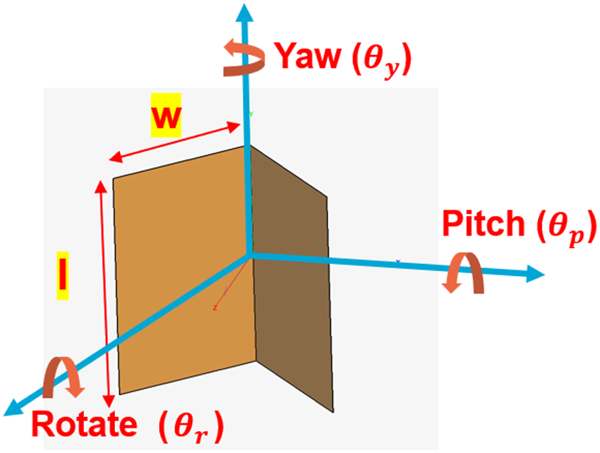
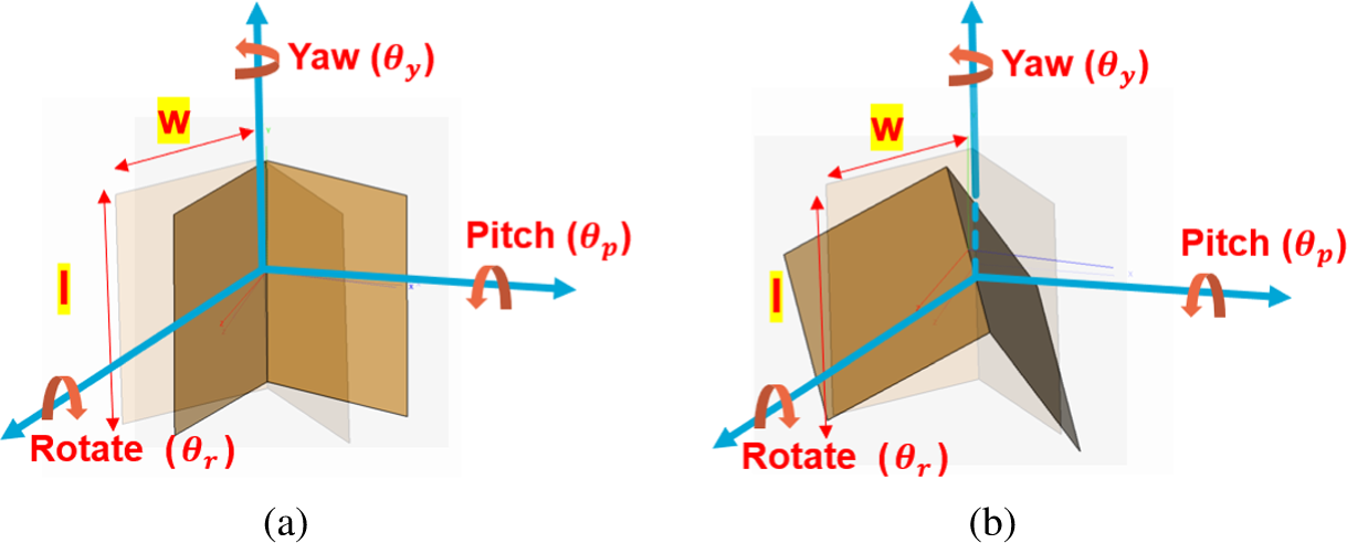
 $l$) of the dihedral, respectively, as illustrated in Fig. 1. The target scattering matrix is defined in Eq. (2) under H-V polarization basis, whereas its components are known as complex scattering amplitudes. The first column of S is measured by transmitting a horizontally polarized wave and employing two antennas horizontally and vertically polarized to record the scattered waves. The second column is measured in the same form but transmitting a vertically polarized wave. The polarimetric scattering matrix of the dihedral, expressed in Eq. (3) under H-V polarization basis, is a function of its angular orientation, with
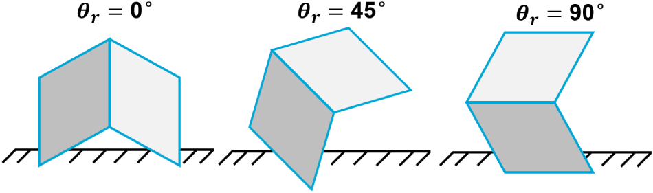
  $\theta_r$ denoting the rotation angle. This angular dependence is a key characteristic of dihedral reflectors, making them a widely preferred reference target in polarimetric radar calibration due to their well-defined and predictable polarimetric scattering behavior. As shown in Fig. 2, the self-rotation of the dihedral allows precise measurement of both co- and cross-polarized components using a fully polarized antenna. For instance, in a radar system equipped with an H-V polarized antenna, the dihedral can be oriented at
  $\theta_r=0^o$ and
  $\theta_r=45^o$ to capture the co- and cross-pol responses, respectively.
Dihedral dimensions and motions definition: yaw, pitch, and rotate.

Dihedral self-rotation ( $\theta_r$).

In practice, measurement setups are often subject to alignment errors between the radar and the dihedral, including possible yaw ( $\theta_y$) and pitch (
 $\theta_p$) angles, as defined in Fig. 1 and shown in Fig. 3.
Yaw ( $\theta_y$) and pitch (
 $\theta_p$) angle variation when
  $\theta_r=0^o$. (a) Pitch angle variation.

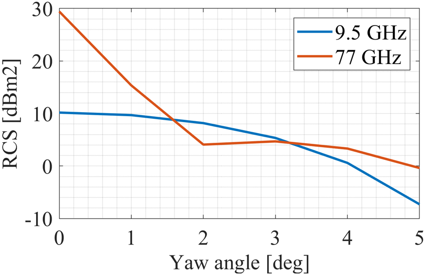
To illustrate the consequences of misalignment, Fig. 4 shows the simulated RCS of a  $90^o$ oriented dihedral, with dimensions 135 mm x 180 mm (w x l), under different yaw misalignment angles, assuming plane wave incidence. At 9.5 GHz, the RCS variation with yaw angle is modest. However, at 77 GHz, the RCS changes sharply by approximately 25 dB between
  $0^o$ and
  $2^o$. Such a degree of yaw angle misalignment can occur easily if the radar and the dihedral are not precisely aligned during the experiment [Reference Tinti, Tejero Alfageme, Duque Biarge, Balcells-Ventura and Pohl17, Reference Liu, Li, Ma, Wen, Xu and Nie22].
Simulated  $90^o$ oriented dihedral scattering RCS with yaw misalignment under two different frequencies.

This significant sensitivity at higher frequencies, such as 77 GHz or beyond, underscores the importance of studying the dihedral scattering behavior under misalignment errors to ensure accurate radar calibration. Due to the increased analytical complexity of dihedral RCS modeling under misalignment errors, especially when both far-field and near-field are needed to be considered, numerical simulations by full-wave tools like FEKO, with accompanying measurements, are preferred [Reference Tinti, Tejero Alfageme, Duque Biarge, Balcells-Ventura and Pohl17].
 \begin{equation}
\sigma_{DH}=\frac{8\pi w^2l^2}{\lambda^2}
\end{equation}
\begin{equation}
\sigma_{DH}=\frac{8\pi w^2l^2}{\lambda^2}
\end{equation} \begin{equation}
S =
\begin{bmatrix}
S_{11} & S_{12}\\
S_{21} & S_{22}
\end{bmatrix}
=
\begin{bmatrix}
S_{hh} & S_{hv}\\
S_{vh} & S_{vv}
\end{bmatrix}
\end{equation}
\begin{equation}
S =
\begin{bmatrix}
S_{11} & S_{12}\\
S_{21} & S_{22}
\end{bmatrix}
=
\begin{bmatrix}
S_{hh} & S_{hv}\\
S_{vh} & S_{vv}
\end{bmatrix}
\end{equation} \begin{equation}
S_{DH}(\theta_r)=\sqrt{\frac{\sigma_{DH}}{4\pi}}
\begin{bmatrix}
-\cos{2\theta_r} & \sin{2\theta_r} \\
\sin{2\theta_r} & \cos{2\theta_r}
\end{bmatrix}
\end{equation}
\begin{equation}
S_{DH}(\theta_r)=\sqrt{\frac{\sigma_{DH}}{4\pi}}
\begin{bmatrix}
-\cos{2\theta_r} & \sin{2\theta_r} \\
\sin{2\theta_r} & \cos{2\theta_r}
\end{bmatrix}
\end{equation}Dihedral scattering simulation under misalignment errors
The simulations discussed in this section were performed in Altair FEKO simulation software at 77 GHz. The details of the simulation setup and the results will be discussed in the following subsections.
Full-wave simulation model
The dihedral corner reflector was modeled in FEKO, as illustrated in Fig. 1, for which the dimensions ( $w$ and
  $l$) can be varied during the simulation. The material selected for the dihedral simulations was a perfect electric conductor with zero thickness for simulation efficiency. The far-field distance of the target can be calculated using
  $\frac{2D^2}{\lambda}$, where D represents the largest dimension of the target. The dihedral mentioned above has a far field of approximately 40 m.
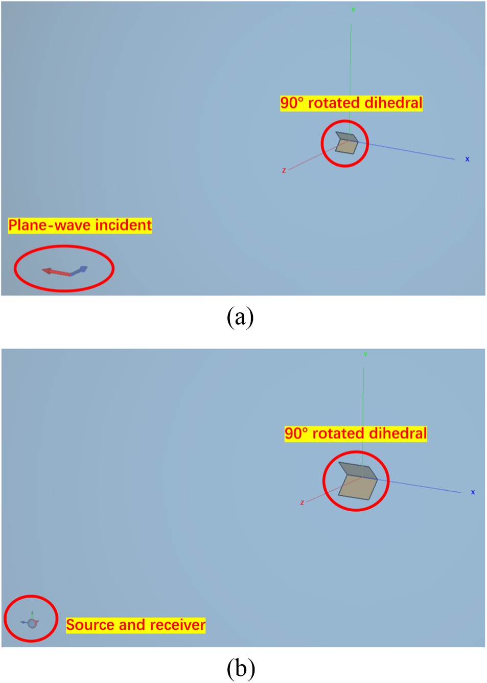
Two simulation setups were employed, differing in the type of source used. For both setups, the Multilevel Fast Multipole Method solver was used instead of the normal Method of Moments solver, as it shortens the simulation time for the electrically large target, like the dihedral used here. The polarization states of the incident wave for both setups are horizontally polarized. The first setup utilized a plane-wave source, as shown in Fig. 5(a), enabling simulation under strict far-field conditions. This setup was used to analyze the dihedral’s far-field scattering behavior under yaw and pitch misalignment. The second setup addressed a practical limitation: during measurements under 77 GHz, the radar-to-dihedral distance was restricted to 3.6 m, sufficient for achieving far-field conditions for the radar, but insufficient for achieving far-field conditions for a dihedral with fixed dimensions (140 mm in width and 200 mm in length) used during the measurement.
FEKO simulation set-up. (a) Simulation setup 1: Plane wave incidence. (b) Simulation setup 2: Spherical mode source and far-field receiving antenna.

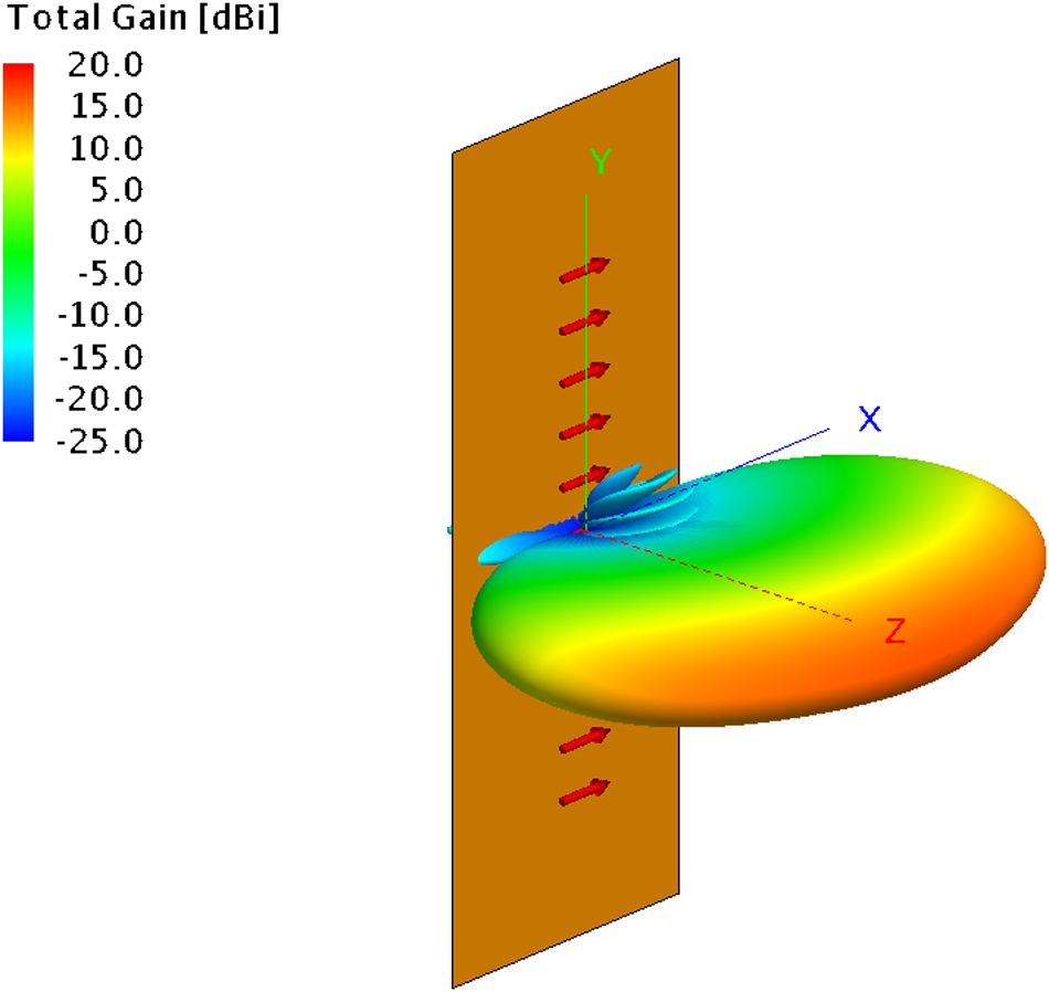
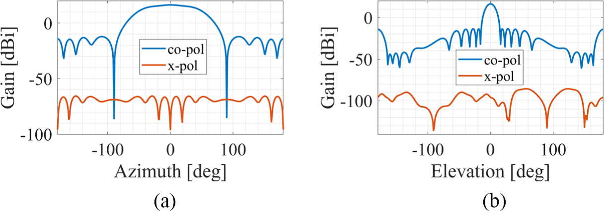
To simulate the near-field effects efficiently, a 1x11 horizontally polarized ideal dipole array was introduced as the source [Reference Ramesan and Madathil23], as depicted in Fig. 6, which mimicks the pattern of the radar under test at the two orthogonal cutplanes around the main lobe and can be replaced by any other 3D pattern data based on the radars or sensing requirements. The element number was selected as a trade-off between simulation accuracy and time. Horizontal polarization was selected to be comparable with the polarization state used in the first simulation setup. The dipole array’s radiation pattern, shown in Fig. 7, offers a wide beamwidth ( $\pm40^o$ at 3 dB) in azimuth and a narrow beam in elevation, a configuration common in automotive sensing [Reference Tinti, Alfageme, Biarge and Pohl6, Reference Yang and Liu24, Reference Zang, Zaman and Yang25], to be comparable with the MIMO automotive radar used in the measurement later. By using the Taylor amplitude tapering to the array, -28 dB sidelobe level and 109 dB cross-polarization isolation were achieved.
An equivalent subarray model with 1x11 dipole array in FEKO, mimicking the pattern of the radar under test in both  $\Phi=0^\circ$ and
  $\Phi=90^\circ$ cuts around the main beam.

Patterns of an equivalent subarray, mimicking the pattern of the radar under test. (a) phi $=0^o$ cut (b) phi
 $=90^o$ cut

The dipole array’s radiation pattern was first simulated in isolation, with the dihedral absent, and the results were exported as spherical mode (.sph) and far-field (.ffe) files. In the second setup of the dihedral scattering simulation, depicted in Fig. 5(b), the spherical mode file was used as the source, while the far-field file was applied to the receiving antenna. Both the source and receiving antenna were co-located, with their distance from the dihedral adjustable for simulation in both near- and far-field.
The complete flow of simulation, including both simulation setups, is presented in Fig. 8. The simulation was performed on a server equipped with 256 G bytes of RAM and two Intel Xeon-Gold 2.1 GHz/20-core Processors. The time cost for a complete simulation round using the first setup is 3.3 min, while for the second setup, the simulation time increased to 5.7 min. It can be seen that by replacing the plane-wave source with the spherical mode source and the far-field receiving antenna, the simulation time has increased by 72%.
Simulation flow chart

Results of yaw misalignment in far-field
In this subsection, the effect of yaw misalignment for varied dihedral dimensions on dihedral far-field RCS will be discussed. The simulation was divided into four sets:
(i) The dihedral was rotated to
 $90^o$, and the width was fixed at 135 mm. Then, for each length from 50 mm to 180 mm, the RCS was simulated under yaw angles from
$0^o$ to
$5^o$.
$90^o$, and the width was fixed at 135 mm. Then, for each length from 50 mm to 180 mm, the RCS was simulated under yaw angles from
$0^o$ to
$5^o$.(ii) The dihedral was rotated to
$90^o$, and the length was fixed at 180 mm. Then, for each width from 50 mm to 180 mm, the RCS was simulated under yaw angles from
$0^o$ to
$5^o$.(iii) The dihedral was rotated to
$0^o$, and the width was fixed at 135 mm. Then, for each length from 50 mm to 180 mm, the RCS was simulated under yaw angles from
$0^o$ to
$5^o$.(iv) The dihedral was rotated to
$0^o$, and the length was fixed at 180 mm. Then, for each width from 50 mm to 180 mm, the RCS was simulated under yaw angles from
$0^o$ to
$5^o$.


To obtain the general trend of the far-field RCS variation and control the simulation time, a step of  $1^o$ was selected for yaw angle scanning from
  $0^o$ to
  $5^o$ in all four simulation sets. The scanning steps were then finer in the chosen ranges of yaw angle as shown in Fig. 14 to capture the local details of the far-field RCS variation. The sizes of the dihedral during the simulation were selected to balance the simulation time and the strength of the dihedral backscattered power.
Figure 9 shows the case (i) of simulation results. Despite the dihedral with a larger dimension having a larger RCS at  $0^o$ yaw angle, its RCS can drop even to a lower level than the dihedral with a smaller dimension when the yaw angle increases. For example, the dihedral with 110 mm length initially has RCS equal to 25 dB drop, but then drops to 2 dB when the yaw angle increases to
  $1^o$. In contrast, the initial RCS of the dihedral with 50 mm length is 18 dB, and it only drops 3 dB after the yaw angle increases to
  $1^o$. Therefore, when the dihedral is rotated to
  $90^o$, its RCS dependency on the change of yaw angle strongly varies with the change of length of the dihedral.
 $90^o$ rotated Dihedral RCS simulation under different yaw angles and varying dihedral length.

The case (ii) of simulation results is shown in Fig. 10. When the dihedral is rotated to  $90^o$, compared with varying dihedral length, the change in dihedral width does not affect the dependency between the RCS variation and the yaw angle. Instead, the increase in dihedral width only affects the overall RCS. The cases (iii) and (IV) of simulation results are shown in Fig. 11 and Fig. 12. It is observed that when the dihedral is rotated to
  $0^o$, either length or width variation will not affect the dependency of the change of RCS on the varying yaw angle. And now the RCS has become stable under the yaw angle misalignment (both near and far field compatible).
 $90^o$ rotated Dihedral RCS simulation under different yaw angles and varying dihedral width.

 $0^o$ rotated Dihedral RCS simulation under different yaw angles and varying dihedral length.

 $0^o$ rotated Dihedral RCS simulation under different yaw angles and varying dihedral width.

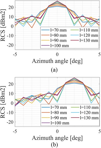
Figure 13 illustrates the simulated far-field scattering patterns of a dihedral rotated by  $90^o$ (
 $\theta_r=90^o$) for different dihedral lengths. When observed at
  $0^o$ azimuth, the RCS consistently increases with the dihedral length. However, in the presence of yaw misalignment, as depicted in Fig. 13(b), the RCS at
  $0^o$ azimuth is influenced by the side lobes and nulls in the dihedral’s scattering patterns. These variations in the side lobes and nulls are directly reflected in the changes in RCS due to yaw misalignment.
Dihedral scattering pattern under varying dihedral length and  $\theta_r=90^o$. (a)
  $\theta_y=0^o$ (b)
  $\theta_y=1^o$

In order to further investigate the influence of the yaw angle on the RCS variation when the dihedral is at  $90^o$, Fig. 14 shows the same results as Fig. 9 but with
  $0.1^o$ simulation step of yaw angle between
  $0^o$ to
  $1^o$ and
  $2^o$ to
  $3^o$. After simulating with
  $0.1^0$ yaw angle step, the RCS variation oscillation can be observed between
  $0^o$ to
  $1^o$ and
  $2^o$ to
  $3^o$ yaw angles. By utilizing the null positions among those oscillations, initial misalignment correction between the radar and the dihedral can be done to avoid no backscattering signal at the null positions, even for an electrically large target.
 $90^o$ rotated Dihedral RCS simulation under different yaw angles and varying dihedral length (with
  $0.1^o$ yaw angle step between
  $0^o$ to
  $1^o$ and
  $2^o$ to
  $3^o$).

Overall, it is observed that when yaw angle misalignment is introduced, and the dihedral is rotated to  $90^o$, the change of the dihedral RCS can range from 20 dB to 30 dB within
  $0^o$ to
  $5^o$ yaw angle. The amount of RCS change can also depend on the length of the dihedral. Due to the null position of the dihedral far-field scattering pattern, the most rapid change of RCS within
  $0^o$ to
  $1^o$ is observed when the length of the dihedral is equal to 120 mm, which should be avoided, while the smallest change happens when the length of the dihedral is equal to 50 mm. By carefully selecting the length of the dihedral, the trend of the RCS change can be controlled within a specific range of yaw angle misalignment. Based on the simulation setup when
  $\theta_r=90^\circ$, it is recommended to select
  $w=135$ mm and
  $l=50$ mm when the yaw misalignment can be controlled within
  $1^\circ$; if the measurement setup does not allow small yaw misalignment within
  $1^\circ$, then it is recommended to use the dihedral with
  $w=135$ mm and
  $l=100$ mm or
  $w=135$ and
  $l=130$ mm to obtain stable RCS under large yaw misalignment angles. On the other hand, when the dihedral is rotated to
  $0^o$, the RCS becomes stable within
  $0^o$ to
  $5^o$ yaw angle. Both length and width variations of the dihedral only affect the overall RCS value.
Results of pitch misalignment in far-field
Same as the yaw angle simulation, the pitch misalignment simulation was also analyzed under four different sets:
(i) The dihedral was rotated to
$90^o$, and the width was fixed at 135 mm. Then, for each length from 50 mm to 180 mm, the RCS was simulated under pitch angles from
$0^o$ to
$5^o$.(ii) The dihedral was rotated to
$90^o$, and the length was fixed at 180 mm. Then, for each width from 50 mm to 180 mm, the RCS was simulated under pitch angles from
$0^o$ to
$5^o$.(iii) The dihedral was rotated to
$0^o$, and the width was fixed at 135 mm. Then, for each length from 50 mm to 180 mm, the RCS was simulated under pitch angles from
$0^o$ to
$5^o$.(iv) The dihedral was rotated to
$0^o$, and the length was fixed at 180 mm. Then, for each width from 50 mm to 180 mm, the RCS was simulated under pitch angles from
$0^o$ to
$5^o$.


During the simulation, the step of pitch angle scanning was set to  $1^o$. As mentioned before, the sizes of the dihedral during the simulation were selected to balance the simulation time and the strength of the dihedral backscattered power.
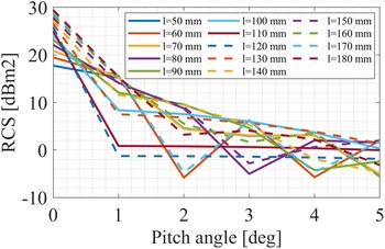
The simulation results of case (i) and case (ii) are shown in Fig. 15 and Fig. 16. It is observed that when the dihedral is rotated to  $90^o$, changing the pitch angle will not affect the RCS value. Besides, both length and width variation here can only influence the overall RCS value. When the dihedral is rotated to
  $0^o$, the pitch angle starts to affect the RCS value. The change of RCS at different pitch angles when the dihedral is rotated to
  $0^o$ can be seen from Fig. 17. In addition, changing the length of the dihedral can affect the trend of the RCS change. Figure 18 shows that when the dihedral is rotated to
  $0^o$, changing the width of the dihedral will only influence the overall RCS value.
 $90^o$ rotated Dihedral RCS simulation under different pitch angles and varying dihedral length.

 $90^o$ rotated Dihedral RCS simulation under different pitch angles and varying dihedral width.

 $0^o$ rotated Dihedral RCS simulation under different pitch angles and varying dihedral length.

 $0^o$ rotated Dihedral RCS simulation under different pitch angles and varying dihedral width.

From the above analysis, it can be seen that including  $0^o$ to
  $5^o$ pitch angle misalignment can already lead to a significant change in dihedral RCS and cause the overall RCS drop for about 20 dB to 30 dB when the dihedral is rotated to
  $0^o$. The length of the dihedral can influence the trend of the RCS change. Based on the simulation setup when
  $\theta_r=0^\circ$, it is recommended to select
  $w=135$ mm and
  $l=50$ mm when the pitch misalignment can be controlled within
  $1^\circ$; if the measurement setup does not allow small pitch misalignment within
  $1^\circ$, then it is recommended to use the dihedral with
  $w=135$ mm and
  $l=100$ mm or
  $w=135$ and
  $l=130$ mm to obtain stable RCS under large pitch misalignment angles. On the other hand, when the dihedral is rotated to
  $90^o$, the RCS becomes stable within
  $0^o$ to
  $5^o$ pitch angle misalignment. Here, both changes of dihedral length and width only affect the overall RCS value. Comparing the results from yaw and pitch misalignment angles, it can be seen that the simulations between
  $0^o$ and
  $90^o$ are symmetrical and vice versa. As an example, the change in the RCS of a
  $90^o$ orientated dihedral with varying yaw angle and dihedral length can be derived from the change in the RCS of a
  $0^o$ dihedral with varying pitch angle and dihedral length. This symmetry simplifies the derivation of the RCS variation of a dihedral caused by the two types of misalignment angles (
 $\theta_y$ and
  $\theta_p$).
Discussion on the near-field effects
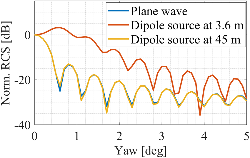
The near-field scattering response of the dihedral was simulated using the second setup described in the previous section. Figure 19 compares the simulation results obtained with a plane wave source and those using the dipole array source. For these simulations, the dihedral dimensions were fixed at 140 mm in width and 200 mm in length, consistent with the size used in subsequent practical measurements.
Simulation results comparison between plane wave and dipole source incidence at two distances ( $\theta_r=90^o$).

The far-field distance for the dihedral with dimensions 140 mm x 200 mm (w x l) is approximately 42 meters. Accordingly, the simulation results using a plane wave closely matched the results obtained when the dipole array source was placed 45 meters away, as shown in Fig. 19, confirming far-field conditions. In contrast, placing the dipole source 3.6 meters from the dihedral will result in the near-field measurement, which coincides with the distance used between the dihedral and the radar during the actual measurement.
As shown in Fig. 19, the RCS difference between the near-field and far-field simulations is approximately 13 dB within the yaw angle range from  $0.5^o$ to
  $2^o$, and drops to 5 dB when the yaw angle is increased. This discrepancy highlights the significant impact of near-field conditions on the dihedral’s scattering response.
Measurement of dihedral scattering under yaw misalignment error
To validate the simulation results, practical measurements have been done using the 77 GHz MIMO radar and the dihedral inside the anechoic chamber. The detailed measurement setup and results are discussed in the following subsections.
Measurement set-up and radar under test
This research utilizes a  $\pm45^o$ polarized MIMO automotive radar operating in the 77 GHz band, designed by HUBER+SUHNER AG. The radar measures the polarimetric scattering matrix, represented by Eq. (4), while the DH scattering matrix under slant polarization basis is shown in Eq. (5). The RF front end includes an MMIC [Reference Ginsburg, Subburaj, Samala, Ramasubramanian, Singh, Bhatara, Murali, Breen, Moallem, Dandu, Jalan, Nayak, Sachdev, Prathapan, Bhatia, Davis, Seok, Parthasarathy, Chatterjee, Srinivasan, Giannini, Kumar, Kulak, Ram, Gupta, Parkar, Bhardwaj, Rakesh, Rajagopal, Shrimali and Rentala26] with four receivers, three transmitters directly connected to a metalized plastic waveguide antenna manufactured using a novel combination of 3D printing and metallization processes developed by HUBER+SUHNER AG [Reference Huegel, Garcia-Tejero, Glogowski, Willmann, Pieper and Merli27]. The antenna is mounted on top of the printed circuit board, as shown in Fig. 20(a). The physical antenna channels are strategically positioned to achieve a fully populated virtual array with
  $\lambda/2$ spacing between the four polarimetric channels (S11, S12, S21, S22), as depicted in Fig. 20(b).
Radar under test [Reference Zhao, Garcia-Tejero, Bouwmeester, Aslan, Krasnov and Yarovoy8]. (a) MIMO topology (b) Polarimetric virtual array

The radar incorporates two subarray types, each offering orthogonal slant polarizations ( $\pm45^o$). These subarrays are based on a linear array of eight open-ended waveguides [Reference Garcia-Tejero, Burgos-Garcia and Merli28]. Simulated radiation patterns for transmitter 1 and transmitter 3 are presented in Fig. 21. The subarrays achieve an elevation (
 $phi=90^\circ$) 3-dB field-of-view (FOV) of
  $9.1^\circ$ and an azimuthal (
 $phi=0^\circ$) FOV of
  $105^\circ$, with a gain around 15 dBi. The cross-polarization discrimination reaches 35 dB at boresight, decreasing to 5 dB at
  $60^\circ$ in the azimuthal plane, due to the inherent geometry of the array.
TX1 (+45 $^\circ$) and TX3 (-45
 $^\circ$) subarray simulated radiation pattern [Reference Zhao, Garcia-Tejero, Bouwmeester, Aslan, Krasnov and Yarovoy8]. (a) phi=
 $90^o$ cut (b) phi=
 $0^o$ cut

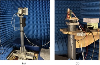
The measurement during this research was performed in the Delft University Chamber for Antenna Tests. A 140 mm x 200 mm dihedral corner reflector was used as the target and placed on a rotatable stand that has two motors that can provide both azimuth rotation and dihedral self-rotation, as shown in Fig. 22(a). The RUT was fixed during the measurement as shown in Fig. 22(b). The distance between the RUT and the dihedral was set to 3.6 m.
 \begin{equation}
S_{\pm 45^obasis}=
\begin{bmatrix}
S_{11} & S_{12} \\
S_{21} & S_{22}
\end{bmatrix}
=
\begin{bmatrix}
S_{+45+45} & S_{+45-45} \\
S_{-45+45} & S_{-45-45}
\end{bmatrix}
\end{equation}
\begin{equation}
S_{\pm 45^obasis}=
\begin{bmatrix}
S_{11} & S_{12} \\
S_{21} & S_{22}
\end{bmatrix}
=
\begin{bmatrix}
S_{+45+45} & S_{+45-45} \\
S_{-45+45} & S_{-45-45}
\end{bmatrix}
\end{equation} \begin{equation}
S_{DH_{slant}}(\theta_r)=\sqrt{\frac{\sigma_{DH}}{4\pi}}
\begin{bmatrix}
\sin{2\theta_r} & \cos{2\theta_r} \\
\cos{2\theta_r} & -\sin{2\theta_r}
\end{bmatrix}
\end{equation}
\begin{equation}
S_{DH_{slant}}(\theta_r)=\sqrt{\frac{\sigma_{DH}}{4\pi}}
\begin{bmatrix}
\sin{2\theta_r} & \cos{2\theta_r} \\
\cos{2\theta_r} & -\sin{2\theta_r}
\end{bmatrix}
\end{equation}Measurement setup in the anechoic chamber. (a) Dihedral setup (b) Radar setup

Measurement results
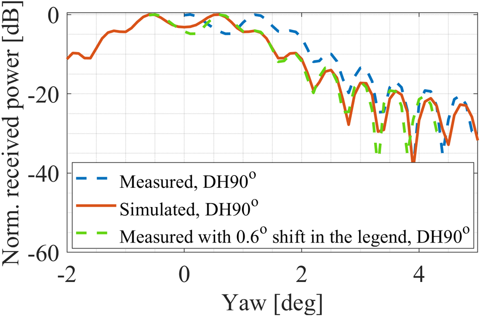
Due to the limitation of the measurement equipment, only the yaw misalignment measurement was done. Figure 23 shows the measurement results, represented by the dashed lines. For comparison, the simulation result is included for  $\theta_r=90^o$ in both near- (source at 3.6 m) and far- (source at 45 m and plane wave incident) field, represented by the solid lines; both the measurement and the simulation were done with the
  $0.1^o$ step when scanning the yaw angle. The results are normalized at
  $0^o$ yaw angle. Each result was normalized according to its own maximum.
Measurement (dashed-line) and simulation (solid-lines) results comparison under yaw misalignment angle.

It can be seen from Fig. 23 that when the dihedral is rotated to  $0^o$, the received power is stable over the yaw misalignment angle, as expected according to the simulation results. The overall variation of the received power is within 1 dB. In contrast, when the dihedral is rotated to
  $90^o$, the received power dropped for about 30 dB when the yaw angle reached
  $5^o$. By comparing the measured results at
  $\theta_r=90^o$ and the corresponding simulated results at near- and far-field, it can be verified that the dihedral was measured in its near-field during the measurement.
From the measurement result of the  $90^o$ rotated dihedral and the corresponding simulation result in the near-field, it can be observed that there is an overall mismatch between the measured (red dashed curve) and the simulated (purple solid curve) results. In order to better observe this mismatch, the simulation range was extended to
  $\theta_y=-2^o$ and compared with the measured result from
  $\theta_y=0^o$ to
  $5^o$ as shown in Fig. 24. After shifting the entire measured curve
  $0.6^o$ to the left, the measured and the simulated results are well-matched as shown in Fig. 24. This overall shift in the curve comes from the moving precision of the step motor that controls the yaw angle scanning.
Misalignment between the measured and simulated results when  $\theta_r=90^o$.

Impact of misalignment errors in polarimetric phase response calibration
Calibration method
The calibration performed in this subsection aims to accurately obtain the polarimetric phase difference between the polarimetric scattering matrix coefficients for better target characterization.
The calibration method used during this research is extended from the method proposed in [Reference Zhao, Garcia-Tejero, Bouwmeester, Aslan, Krasnov and Yarovoy8], where the calibration matrix was introduced, which can be directly multiplied by the raw radar data for the polarimetric phase calibration.
The raw measurement data consists of a 12x750x16x20 complex 4-D matrix, where 12 represents the number of channels, 750 is the number of samples per chirp, 16 denotes the number of chirps per frame, and 20 signifies the number of frames.
To obtain the reference data for calculating the calibration matrix, the measurement of the dihedral was done at  $\theta_r=45^o$ and
  $\theta_r=0^o$, both without any misalignment angle (
 $\theta_y=\theta_p=0^o$). The co-pol reference data was obtained from the measurement at
  $\theta_r=45^o$, and the cross-pol reference data was obtained from the measurement at
  $\theta_r=0^o$. The calibration matrix was calculated using the method proposed in [Reference Zhao, Garcia-Tejero, Bouwmeester, Aslan, Krasnov and Yarovoy8] and then applied to the measured data when the yaw angle was present. The polarimetric channels’ phase difference was calculated between
  $S_{12}$ and
  $S_{21}$. According to the scattering matrix of the dihedral under
  $\pm45^o$ polarimetric basis, the polarimetric phase difference between the cross-pol channels
  $S_{12}$ and
  $S_{21}$ should be
  $0^o$ when the dihedral is rotated to
  $\theta_r=0^o$ and
  $\theta_r=90^o$.
Yaw angle misalignment errors
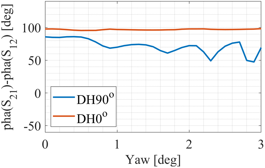
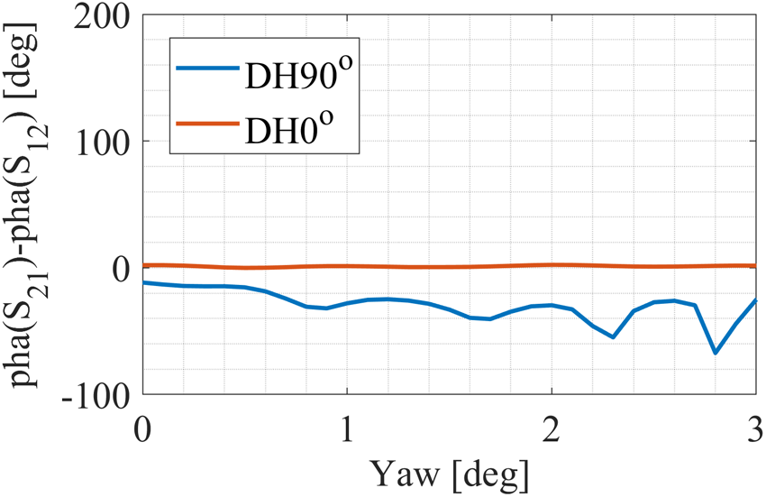
The uncalibrated polarimetric phase differences of the measured data are shown in Fig. 25, while the calibrated results are presented in Fig. 26. After calibration, the polarimetric phase difference for the  $0^\circ$ rotated dihedral stabilizes around
  $0^o$, with a mean value of
  $1.2^\circ$ and a standard deviation (s.t.d) of
  $0.6^\circ$. In contrast, the
  $90^\circ$ rotated dihedral shows less stability in its calibrated polarimetric phase difference compared to the
  $0^\circ$ rotated dihedral. Specifically, the s.t.d for the
  $90^\circ$ rotated dihedral increases significantly to
  $12.3^\circ$, and its mean value shifts to
 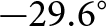 $-29.6^\circ$. The additional phase offset occurred on the dihedral with
  $\theta_r=90^\circ$ is due to the RCS reduction under yaw misalignment error as shown in Fig. 24. Such RCS reduction can lead to lower SNR and bring additional phase noise to the measurement.
Uncalibrated cross-pol polarimetric phase difference from the measurement.

Calibrated (under no misalignment assumption) cross-pol polarimetric phase difference from the measurement.

Conclusion
This study presents a detailed investigation into the effects of misalignment errors, specifically yaw and pitch deviations, on the scattering response of dihedral reflectors in mm-wave polarimetric MIMO automotive radar. Simulations and measurements at 77 GHz revealed significant RCS variations, with changes up to 30 dB observed within small misalignment ranges (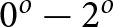 $0^o-2^o$). Misalignment effects were less pronounced when the dihedral was oriented at specific angles (
 $\theta_r=0^o$ for yaw and
  $\theta_r=90^o$ for pitch), offering configurations for stable calibration setups. To achieve stable RCS under misalignment conditions, a dihedral with dimensions
  $w = 135$ mm and
  $l = 50$ mm is recommended when pitch or yaw misalignment can be controlled within
  $1^\circ$. For larger misalignment angles, more robust configurations such as
  $w = 135$ mm and
  $l = 100$ mm or
  $l = 130$ mm are preferred.
The analysis highlighted the trade-off between dihedral size and sensitivity to misalignment. Larger dihedrals provide stronger reflections but are more sensitive to misalignment compared to smaller ones, emphasizing the importance of selecting dimensions that balance RCS strength and stability.
Additionally, near-field effects were shown to influence calibration, with the largest RCS discrepancies between near- and far-field measurements occurring within  $0^o-2^o$ yaw angles. The polarimetric calibration method proved to be effective for maintaining a stable phase response for a
  $0^o$ rotated dihedral, though increased phase variation was observed at
  $\theta_r=90^o$.
Acknowledgements
This research was supported by the National Growth Fund through the Dutch 6G flagship project “Future Network Services.” The authors would like to express their sincere gratitude to Pascal Aubry for his exceptional support in establishing the measurement environment and providing assistance with the measurements.
Declaration of interests
The authors report no conflict of interest.

Changxu Zhao received the B.Sc. degree in Electrical Engineering and Intelligent Control from the Shanghai Maritime University, Shanghai, China, in 2020, and the B.Sc. degree in Engineering (Cum Laude) from the HZ University of Applied Sciences, Vlissingen, The Netherlands, in 2020. Afterward, he continued his master’s studies at Delft University of Technology (TU Delft). In 2023, he completed his master’s thesis (Cum Laude) and graduated from the Microwave Sensing, Signals and Systems (MS3) group at TU Delft. In November 2023, he continued his research in the MS3 group as a Ph.D. candidate. His current research interests include polarimetric calibration and sensing in automotive radar applications.

Yanki Aslan received the B.Sc. degree with double specialization in communications and microwaves/antennas from the Department of Electrical and Electronic Engineering, Middle East Technical University, Ankara, Turkey, in 2014, and the M.Sc. (cum laude) and Ph.D. degrees (cum laude) in electrical engineering from Delft University of Technology, Delft, The Netherlands, in 2016 and 2020, respectively. Following his Postdoctoral Research with Delft University of Technology in the Microwave Sensing, Signals and Systems (MS3) Group, he started as an Assistant Professor with TU Delft in April 2021. His current research interests include phased arrays for next-generation communication and sensing systems, array optimization, multibeam antennas, front-end architectures, and beamforming algorithms. Dr. Aslan was one of the recipients of the IEEE AP-S Doctoral Research Grant in 2018 and the EuMA Internship Award in 2019.

Alejandro Garcia-Tejero received the B.Sc. and M.Sc. degrees in telecommunications engineering from the Universidad Politécnica de Madrid, Spain, in 2016 and 2018, respectively. In 2017, he joined the École Fédérale de Lausanne, Lausanne, Switzerland as a Guest M.Sc. Student. He is currently working as an RF/Antenna Engineer with Huber+Suhner AG, Switzerland. His research interests include RF circuits, communication, and automotive radar antennas.

Wietse Bouwmeester received the B.Sc. degree in electrical engineering from the Delft University of Technology in 2016, and the M.Sc. degree in electrical engineering from the Delft University of Technology, with a focus on telecommunications and sensing systems. He graduated cum laude on the design of a conformal phased array antenna commissioned by ASTRON, the Dutch institute for radio astronomy. In May 2020, he joined the Microwave Sensing, Signals, and Systems group of the TU Delft as a Ph.D. candidate, where he was working on polarimetric approaches to classify road surfaces and other targets with mm-wave radar for automotive applications. He obtained his doctoral degree in 2024.

Alexander Yarovoy received the Diploma (Hons.) in Radiophysics and Electronics from Kharkov State University, Ukraine, in 1984, and the Candidate and Doctor of Physics and Mathematical Sciences degrees in 1987 and 1994, respectively. He joined Kharkov State University as a Researcher in 1987, becoming a Full Professor in 1997. From 1994 to 1996, he was a Visiting Researcher at the Technical University of Ilmenau, Germany. Since 1999, he has been with Delft University of Technology, The Netherlands, where he chairs the Microwave Sensing, Systems and Signals Group. He has authored over 500 scientific papers, seven patents, and 15 book chapters. His research interests include high-resolution radar, microwave imaging, and UWB antennas. He received the European Microwave Week Radar Awards in 2001 and 2012 and the ACES Best Paper Award in 2010. He has also held leadership roles in major conferences and served as an editor for prominent journals.


 Open access