

Introduction
In 2011, the Ice Drilling Design and Operations (IDDO) group at the University of Wisconsin–Madison began a conceptual design for an agile ice-core drilling system that could recover 98mm diameter ice cores to 1500m depth, based on a set of science requirements drafted by the US ice-core community. The system includes the core-processing system, drilling structures and power distribution system. This approach was taken with the goal of providing the science community with a complete drill system and to simplify the logistics process of deploying this system to the field. Detailed design and fabrication of the drill system began in 2012. The drill system will be tested near Summit Station, Greenland, in spring 2014. The drill will then be deployed to the South Pole for the South Pole Ice (SPICE) Core project, a two-season project starting in November 2014 to recover a 1500 m ice core.
Drill System Design
From the start of the project, there have been a few main design objectives that have driven the overall design of the system. All equipment must be able to be broken down into small enough pieces for transport in a Twin Otter aircraft. While this may not always make the best logistic sense, it does require that all pieces can be moved and loaded without using heavy equipment. This reduces the logistical requirements and the cost of deploying the drill. The total shipping weight for the drill system is 9676 kg, with the heaviest individual piece weighing 458 kg. It should be possible to set up the system, drill to 1500m depth and remove the equipment from the field in two Antarctic production seasons. Brittle ice drilled during the second season is planned to remain on site until the third season. The drill system is designed for operation in a wide range of polar conditions from the temperate/high snow accumulation coastal areas of Antarctica to the extreme cold and high altitude of interior sites.
Three different drill design options were initially considered. They were downsizing and simplifying IDDO’s deep ice-sheet coring (DISC) drill, designing a new drill and starting with a proven design from another engineering group. It was determined that building a drill based on the Danish Hans Tausen drill design (Reference JohnsenJohnsen and others, 2007) was going to best meet the science and engineering requirements for this project. Details of much of the final drill design were worked out in collaboration with the Center for Ice and Climate, Denmark, and the Antarctic Research Center, Victoria University of Wellington, New Zealand.
All surface components are designed to operate to −40°C and all downhole components to −57°C. The winch and tower were designed for up to a 10 kN core break (Reference Mulvaney, Alemany and PossentiMulvaney and others, 2007). Drilling and core-processing operations are designed around a ten-person team working a 24/6 schedule. The team will work in three shifts with three people per shift and an overall lead driller. Figure 1 shows the layout of the drill system.
Drill site layout.

Drilling Tent
The drilling equipment is housed within a fabric-covered tent. The floor level inside the tent is recessed 1.4 m below grade to reduce the height of tent required and to help keep the interior of the tent cool. The floor is covered with 0.5 m × 1.0 m × 30 mm thick sections of polyethylene grid material to provide a reusable slip-free work surface. Stairs at either end of the trench provide access. The tent is custom-made by WeatherPort and features a steel frame with a fabric cover. It is 19.5 m long, 4.9 m wide and 3.1 m high as shown in Figure 2. Both end walls have personnel doors and a large double-zipper entry for moving larger equipment in and out. The fabric is a PVC-impregnated polyester cotton blend with an acrylic top coat. The fabric has a cold-crack resistance to lower than −80°C and it remains very pliable at −40°C for ease of set-up. The structure has been engineered for a snow-load rating of 269 kgm–2 and 65 kt (120 km h−1) winds. The cover is white and non-insulated to provide good natural lighting. There is a red strip on each end to improve visibility in poor weather. Four 305 mm diameter wind-directional vents were installed on the ridgeline to provide convection cooling. Inside the drill tent is a smaller, 1.2 m wide and 2.4 m long, insulated tent which will serve as the drill control room. Three windows were installed to provide the operators good viewing of all operations. The space is heated with an electric heater, and the break resistor for the winch motor provides supplemental heat.
Drilling tent.

Ventilation is provided by two fan systems. An 1100CFM (0.519m3s−1) centrifugal ventilator draws air from the bottom of the slot and exhausts outside the drill tent. The core-dryer and cable-cleaner vacuum systems are also vented into this system. The second ventilator is located next to the centrifuge and displaces 450 CFM (0.212 m3 s−1). The combined airflow of the ventilators will provide seven air-volume exchanges per hour.
Drilling Fluid
Estisol 140 has been selected as the drilling fluid for this project. Based on laboratory and field testing done by the Center for Ice and Climate (S.G. Sheldon and others, unpublished information), the fluid density will be between 922 kgm–3 at −41°C and 930 kgm–3 at −51°C. This should closely balance the isostatic pressure of ice for the SPICE Coring project which has a minimum ice temperature of −51°C (Reference PricePrice and others, 2002). The kinematic viscosity of drilling fluid in this temperature range is 3–8 × 10⁻⁶ m2 s−1. The low temperatures at the South Pole combined with the passive and active ventilation in the drill tent should keep the odor to a tolerable level.
Pilot Hole and Casing
The borehole will be started with the IDD configured for dry drilling. The pilot hole will then be reamed in two steps to a final diameter of 229 mm using a set of reamers that attach to the motor section. The first reamer will enlarge the borehole to 178mm, and the second reamer will enlarge it to 229 mm (Fig. 3). A special bearing section has been designed that mounts between the reamers and the motor section to carry all radial and axial loads. This was implemented to prevent damage to the output shaft on the motor section, which we have seen on past drills, due to the large moment loads the reamers place on it. Cuttings are transported from the cutters into the head and then fall into a 3 m long catch tube. A plug at the end of the tube is easily removed for emptying the chips. For the South Pole project, the borehole will be reamed to 120–130m depth. The casing will be the same high-density polyethylene pipe that was first used on the West Antarctic Ice Sheet (WAIS) Divide Core project, only in a smaller diameter. For the IDD it will be 219 mm outer diameter (OD) × 192 mm inner diameter (ID) fabricated in 4.6 m sections with threaded together connections. The casing shoe will be sealed to the ice by a face seal and three external O-rings made from silicone. The O-rings are sized to have a close fit to the borehole, so once they are exposed to the drilling fluid they will expand and create a seal with the ice. This shoe design provides some compliance so it can keep a seal with the ice as the casing and ice shift. The IDD winch and tower have been designed to allow them to be used to set the casing. All operations for creating and reaming the pilot hole can be done in one set-up and without using additional equipment or a separate drill.
229 mm reamer. The housing at the top of the picture mounts to the motor section. A slewing bearing at the bottom of the housing carries the axial and radial load of the tool to prevent damage to the motor section drive.

Winch and Tower
A tilting-tower design was chosen for its ease to set up and ability to position the drill horizontally for servicing. The 6 m long tower is fabricated from 132mm square aluminum tubing with a 13 mm wall. It breaks down into 1 and 2 m long sections for ease of transport and assembly. The drill is supported on the tower by four adjustable height rest assemblies that can be positioned at any point along the tower on a rail. The aluminum top sheave has a 1.5 m circumference and is instrumented with a load pin and ring-type encoder for measuring cable payout. The ring encoder permits a very compact sheave design while providing 0.2 mm payout resolution. Cable is spooled on to a removable all-aluminum winch drum with integral Lebus groove. The winch is driven by a 7.5 kW 460V a.c. brushless servomotor with resolver feedback and built-in brake. It is coupled to the winch drum by a helical bevel gear reducer with a 56.38: 1 reduction. This provides fully controlled line speed from 0.5 mms−1 to 1.4 ms−1 and enough pulling power to do a 10 kN core break. To ensure the cable winds evenly on the drum, a custom-built level wind, using the similar control method we first designed for the DISC drill, has been implemented. The level wind is a self-contained device, requiring only 24V d.c. power, and operates fully independently of the winch (Fig. 4). The control system monitors the cable angle between the winch drum and fairlead roller and sets the required speed to keep this angle near zero. Further information on this novel method for cable level winding can found in a related paper (Reference Mortensen, Johnson and ShturmakovMortensen and others, 2014). The winch drum and drive are mounted on a trunion fabricated from stainless steel that pivots with the tower. There are two main advantages with this design. First, the drill does not move up or down the tower as it is tilted. Second, the winch drum translates vertically 15 cm as the trunion tilts, which makes it possible to install and remove the winch drum without additional rigging or lifting equipment. To remove the drum, two wooden rails are first placed on the tower base. The trunion is then tilted back until the drum rests on the rails. The drive flange is unbolted from one side, and the bearing block from the other, freeing the drum so it can be rolled out and into its shipping case. The tower is tilted using an electric linear actuator with built-in fail-safe brake and provides full variable-speed control. The winch-and-tower assembly mounts to an all-aluminum base frame, 1.7 m long and 1.2 m wide. A model of the complete winch-and-tower assembly is shown in Figure 5.
Self-contained level wind system.

The IDD winch-and-tower assembly.

Winch Cable
The cable is manufactured by Rochester Wire & Cable. The outer two armor layers of the 5.7 mm diameter cable are made from galvanized high-strength steel, and the core contains three #24 AWG conductors. The conductors are insulated with DuPont FEP, which has excellent low-temperature properties and is not affected by the Estisol 140 drilling fluid. Two of the conductors are tied together for power, the third is used for communications, and the armored jacket is used for ground. The breaking strength is 24.5 kN with an elongation of 0.58 m km−1 kN−1 and a weight in air of 1.3 kN km−1. The winch drum is loaded with 1600m of cable, giving a total cable weight of 2.2 kN.
Drill Design
The proven design of the Danish Hans Tausen drill was the basis for the IDD design. The IDD has been designed to recover 2 m long cores to balance the trade-offs between the length of the drill, which directly affects the size of all equipment on the surface, and the amount of ice recovered per drill run. This keeps the size of all equipment manageable and within the design goals. Table 1 presents a summary of the drill dimensions.
Summary of the IDD dimensions

The winch cable attaches in the bearing housing of the anti-torque using the helical rods and insert from an EVERGRIP cable termination from PMI Industries pared with a custom split housing of our own design. The electrical conductors are terminated with a Fischer Connectors Core Series connector. This arrangement makes it possible to quickly and easily separate the fully terminated winch cable from the anti-torque while maintaining a mechanical connection that is rated to the full strength of the cable. After the bearing housing, which lets the cable rotate independently of the drill, a four-channel slip ring is positioned. A torque tube connects the bearing section to the slip ring and houses the electrical connection and antitorque slip sensor. Electrical connection between the slip ring and motor section is made with a patch cable terminated with a Fischer connector at the slip ring end and a pressure-rated SeaCon connector on the motor section end. All connectors can be potted to prevent the ingress of water should that scenario arise. The Fischer connectors and the slip ring are sealed to IP68 standards, so they will eventually fill with drilling fluid as the drill descends the fluid-filled borehole. If water is encountered at the bottom of a borehole it will not be able to enter since the components will already be filled with drilling fluid. Three leaf spring blades made from 1095 spring steel surround the bearing housing, torque tube and slip ring and interact with the borehole wall to center the drill and keep the stationary portion of the drill from rotating. A single nut at the top of the anti-torque adjusts the arch of all three blades and determines how much force the blades put on the borehole wall. A diagram of the antitorque section is shown in Figure 6.
Views of the anti-torque and motor sections.
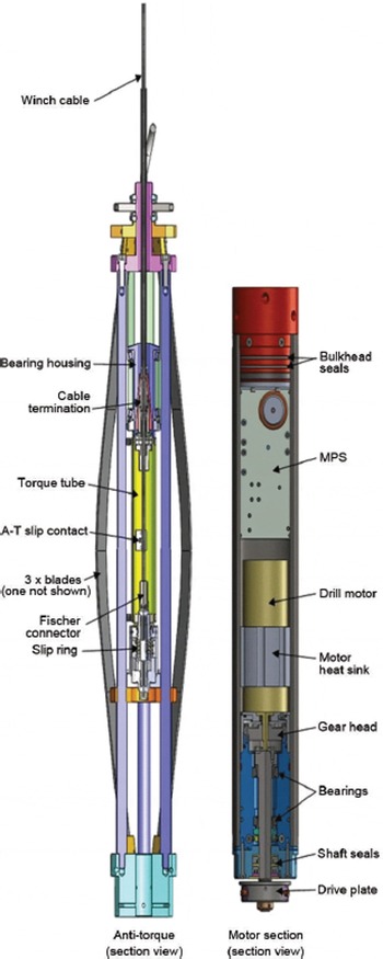
Following the anti-torque is the motor section (Fig. 6). It is a pressure-tight housing 0.72 m in length and contains an electronics package, the drill motor and the final drive components. The tubular housing is made from chrome-plated DOM ST52.3 steel with removable bulkheads at either end so the internal components can be serviced. The sonde electronics package consists of a motor power supply (MPS) with a basic bidirectional communication loop to command the motor which direction to turn and send a signal if the anti-torque slips. A block diagram of the MPS is shown in Figure 7. The MPS is designed to handle an input voltage of up to 600V d.c. The output voltage varies with the input voltage, giving proportional speed control up to the motor’s rated voltage of 220 V d.c. At this point any additional power supplied to the MPS is applied to keep the motor at constant speed, and the output voltage remains at 220 V d.c. Over-voltage and over-current protection features are also built into the MPS to protect the motor. This power supply design makes it possible to supply >500W of shaft power at the drill over the small-diameter conductors of the winch cable. Heat generated by the MPS is conducted out into the borehole through its base plate mounted to the upper bulkhead, both of which are made from aluminum. A Parvalux PM60 bushed d.c. motor is coupled to an 80: 1 ratio Harmonic drive gearhead. This gives a maximum output shaft speed of 63 rpm with 70 Nm of torque, assuming an 80% efficacy. The output shaft is supported by a set of tapered roller bearings which are designed to carry the full axial load of a core break. Aeroshell fluid #4 hydraulic oil provides the lubrication for the gearbox and bearings. Sealing of the upper and lower bulkheads is done with a pair of hydraulic piston seals supplied by American High Performance Seals (AHPS). The two-part seals consist of a rectangular cross-section outer seal ring, made from a proprietary Teflon-based material, which is backed up by an energizer O-ring. The output shaft seal package was also designed by AHPS and can be easily replaced without having to disassemble the entire motor section. It consists of two seal rings with spring energized lips running against the rotating shaft, external O-rings that seal against the housing preventing the seal rings from rotating, and an anti-extrusion ring backing up each of the seal rings.
Motor power supply.

Connecting to the bottom of the motor section are the chips chamber and the hollow shaft which drives the core barrel. Two configurations of the chips chamber have been made, one for dry drilling and one for wet drilling. They differ only by the wet chamber having 7200 1.5 mm diameter holes drilled in it to aid in filtering the drilling fluid from the chips. The overall length of the chips chamber tube is 2.6 m with a usable length for chips of 2.3 m when configured with the pump, yielding a fill concentration of 56.5%. The tubes are fabricated from vacuum-annealed rolled and fusion-welded 304 series Stainless Steel. The drive plate on the motor section attaches to the coupling at the top of the 30 mm diameter hollow shaft with three quarter-turn spring-loaded pins. Below the coupling is a valve plate that opens when the shaft is turned in reverse and closes when the shaft is turned forward. A similar valve is located at the lower end of the hollow shaft. These valves are set open when the drill is descending the fluid-filled borehole to permit faster tripping speeds by reducing hydrostatic drag. The valves automatically close when the shaft is run forward, allowing the space between them to fill with cuttings and transport the cuttings back to the surface without being flushed out. Single-turn helical augers, often called boosters, can be placed on the hollow shaft at any position between the valves to facilitate the transport and packing of cuttings in the chips chamber. They attach to the hollow shaft with collet-type clamps located at either end of the booster. A 12-valve double piston pump, which is an exact copy of the Danish pump, can also be installed just above the lower valve for wet drilling (Reference JohnsenJohnsen and others, 2007). At the end of the hollow shaft is a bayonet housing that attaches to and drives the core barrel.
Following the chips chamber is the outer tube which contains the core barrel. IDDO innovated the first use of filament wound fiberglass tubing for the outer tube (Fig. 8). The tubing is fabricated by helically winding fiberglass filament coated in epoxy on a mandrel containing 24 sawtooth-like features running the length of it. When the tube is removed from the mandrel, the inverse tooth pattern remains on the inside of the tube. Finally, the tubes are centerless ground to final diameter, leaving a smooth and accurate OD. The resulting product is a very round and straight tube that costs a fraction of tubes made from metal. The outer tube attaches to the chips chamber with a slip fit connection that is held in place with three locking pieces that fit into a keyhole shape detail. The core barrel is 2.24 m long overall, giving enough room to recover a 2 m long core, and is manufactured from 304 series Stainless Steel using the same process as the chips chamber tubing. The top of the barrel has three channels machined into it that the bayonet housing pins run in. These details serve as a quick detach mechanism allowing the drill to be recovered, leaving the core barrel and cutter head behind, should the cutter head become irretrievably stuck while drilling. Also, using mass of the upper portion of the drill, it can be used as a slide hammer to break core. Two configurations of this barrel have also been made. The first has three HDPE flights with a 35° pitch angle. The second configuration, used for wet drilling with the pump, has three aluminum flights with a 48.5° pitch angle and at 2 mm high only partially fills the annulus between the core barrel tube and outer tube. These partial height flights provide a stirring action, and rely on the pump flow to provide the chip transport. Near either end of the core barrel, a short section of full-height HDPE flights was added in for guidance to keep the core barrel centered in the outer tube.
Fiberglass outer tube with dry core barrel and cutter head.

The cutter heads follow the Danish design, having three cutters with a 42.5° rake angle and 15° relief angle. Two widths of cutters were made; both make 98 mm diameter cores. The narrower kerf cutter produces a 126 mm diameter borehole while the wide kerf cutters make a 129.6 mm diameter borehole and are used for wet drilling to provide more clearance around the drill for improved fluid flow. The three core dogs are double sprung, meaning a light spring is used to keep them retracted while a heavier spring is used to set a pre-load against the ice core. This method reduces damage to the ice core if the previous break was uneven. Two different cutter head configurations have been built. Again, one is used for wet drilling and one for dry drilling. The only difference is that the wet head has a smaller OD, permitting improved fluid flow around it. Shoes mounted on the back of the cutters will provide cutting pitches between 0.5 and 3.0 mm per tooth. The head attaches to the core barrel using three headed bushings to pin it in place.
Control System
The IDD control system has two major components: the control box and the console. The control box, a 0.8 m × 0.6 m × 0.61 m aluminum Zarges case, contains the drives to run the winch and tower, power supply for the drill, and a custom-built interface board that communicates with the downhole drill electronics and the console (Fig. 9). It has an internal heater so it can live outside the control room to conserve space. A wired pendant, which plugs into the control box, is used to control the tower actuator. It incorporates a thumb wheel for proportional speed control and an E-stop button into an ergonomic pistol-grip-style handle. The console lives on a desk inside the heated control room, providing a comfortable work environment for the drill operator. The console is used to control the winch and drill, and monitor the status of the system (Fig. 10). Winch direction is selected with a toggle switch, and speed is controlled with one of two potentiometers. One provides low speed, high resolution and control for coring, while the other controls the full speed range for tripping the drill in and out of the borehole. Drill rotation direction is also selected with a toggle switch, and speed is controlled with a potentiometer. A centrally located E-stop fills out the controls section, which is mounted at a slight incline for operator comfort. An LCi-90i line control monitor manufactured by Measurement Technologies Northwest has been incorporated to monitor cable payout, speed and tension. The unit also has user-definable alarms to alert the operator if any parameters get out of range. Digital displays show the voltage being supplied to the drill and how much current the motor is drawing. A second current meter, with analog display, was included since it is often easier to interpret trends with the indicator movement than on a numeric display. A series of status indicator lights mounted above the LCI-90i tell the operator when the drill is parked at the ‘home’ position on the tower, whether the drill has triggered the hard limit on the tower, whether an E-stop has been set and whether the anti-torque is slipping. A siren, which can be silenced, also alerts the operator if there is an anti-torque slip. Optionally, a computer can be connected to the console via a USB connection to receive and archive data from the LCI-90i along with the drill voltage and current. These data will be displayed graphically using a LabVIEW interface. The software will also display a calculated weight on bit by subtracting the weight the load pin is reading from the sum of the weight of the drill and a calculated weight of how much cable has been paid out.
Control box.

Drill control console.

Core Processing
After the drill has been parked on the tower and tilted horizontal, the hollow shaft and core barrel are detached from the rest of the drill and pulled out either by hand or with a hand crank winch located at the end of the pull-out table. The cuttings are collected in a tub located between the end of the drill trench and the pull-out table for later processing. The core barrel, containing the core, is transferred by hand laterally to the core-processing line. A series of rail assemblies are mounted and aligned on a row of benches that runs the length of one side of the drill tent to form the core-processing line (Fig. 11). The ice core is pushed from the core barrel and through a specially designed fluid-evacuation device (FED), which, using suction, removes most of the drilling fluid from the core surface. Ductile ice cores will proceed down the line, the length will be measured and then they will be cut into 1 m lengths using a circular saw. At this point, they can be put into lay-flat tubing and packed for shipment. If it is found that the combination of the FED and towel drying does not remove enough drilling fluid to permit immediate packing, the cores will be put into a buffer to dry further. Cores recovered from the brittle ice zone will be placed into polyethylene netting as they exit the FED. An initial length measurement will be taken and they will then be transported directly into a 4.3m wide, 7.3 m long trench that will be excavated off to the side of the drill trench. The cores will rest for 1 year before being cut and packed. A ladder lift will be used to move packed ice-core boxes from the trench to the surface, where they will be palletized for shipping.
(a) Core-processing line. (b) FED assembly with fiberglass netting deployment sleeve.

Chips and Fluid-Handling Systems
The slurry of ice chips and drilling fluid removed from the chips chamber is transferred to a centrifuge manufactured by Kinefac Corporation. The 19L centrifuge basket is lined with a removable fabric bag permitting easy removal of the cuttings after the fluid has been extracted from them. The cuttings will then be carried out of the drill tent and put in a designated chips disposal area. Recovered fluid drains to a collection tank and passes through a final filter before flowing through a hose and back to the borehole. Drilling fluid is brought to the site in metal drums and staged next to the drill tent. A drum pump will be used to transfer the fluid to a manifold in the drill trench. Fluid can either be sent directly to the borehole or diverted to a flushing tool for cleaning chips out of the 7200 holes in the chips chamber. Fuel bladder material will line the slot end wall and floor to direct drilling fluid coming off the tower back to a catch pan around the casing and into the borehole. Fluid carried up on the winch cable will be recovered using a vacuum connected to a custom-built cable cleaner based on that used by the Danish drilling program at the North Greenland Eemian Ice Drilling (NEEM) site. A bailer has been built for recovering cuttings if they are not fully recovered by the drill. It consists of a perforated mesh tube, configurable to either 1 or 2 m long, with a check valve assembly at the lower end. The baler mounts to the motor section in place of the chips chamber. Chips are collected in a fabric mesh sleeve inside the tube as the tool is lowered in the fluid. The valve assembly, which can be removed without tools, retains the chips in the baler while returning to the surface, yet permits easy removal of the chips when on the surface.
Power System
The logistics providers will be supplying the generators for the test season in Greenland and also for the SPICE Coring project. These generators will power not only the drill system, but will also supply any other power needed for the camp. A 460 V 3-phase power feed will come into the drill tent to feed the IDDO-supplied power distribution system. The power distribution system consists of a 460 V 3-phase panel which powers the larger loads and also a 45 kVA step-down transformer that feeds a 208/110 V panel for all other power needs. Power requirements are estimated to not exceed 20 kW at sea level.
Conclusion
Design and fabrication of IDDO’s new intermediate depth coring drill system is complete and ready for field-testing in Greenland in spring 2014 before deploying to the South Pole for the two-season SPICE Core project. The drill is designed to recover 98mm diameter cores 2 m long to a depth of 1500m. The design incorporates the drilling, core processing, power distribution and drill structures in one integrated system for ease of deployment and operation.
Acknowledgements
We thank the Center for Ice and Climate, Copenhagen, Denmark, and the Antarctic Research Center, Victoria University of Wellington, New Zealand, for their collaboration and input on the drill design. The Ice Drilling Program Office (IDPO) was instrumental in establishing this project. We thank the numerous machine shops and custom parts vendors, without whom this project would just be a pile of paper. Funding from the US National Science Foundation (NSF) Office of Polar Programs made this all possible. This work was supported under NSF Cooperative Agreement OPP-0841135 and CA# 1327315.


