


1. Introduction
Divertors play a critical role in magnetic confinement fusion devices by managing plasma exhaust, including helium ash from deuterium–tritium reactions, impurities and neutrals. The divertor serves as a barrier between the hot core plasma (temperatures around
 $\sim$
10 keV) and the device walls, reducing temperatures to
$\sim$
10 keV) and the device walls, reducing temperatures to
 $\sim$
1–2 eV at the divertor targets. Effective divertors must handle high heat fluxes, localise neutrals so they can be efficiently pumped and maintain plasma purity by preventing impurities from the wall from reaching the core (Burnett et al. Reference Burnett, Grove, Stix and Wakefield1958; Krasheninnikov & Kukushkin Reference Krasheninnikov and Kukushkin2017).
$\sim$
1–2 eV at the divertor targets. Effective divertors must handle high heat fluxes, localise neutrals so they can be efficiently pumped and maintain plasma purity by preventing impurities from the wall from reaching the core (Burnett et al. Reference Burnett, Grove, Stix and Wakefield1958; Krasheninnikov & Kukushkin Reference Krasheninnikov and Kukushkin2017).
In stellarators, non-axisymmetric magnetic fields offer flexibility but complicate divertor design. Unlike tokamaks, where axisymmetric poloidal X-point divertors are standard, stellarator divertors often rely on resonant islands, ergodic layers or non-resonant structures, each with trade-offs in sensitivity to plasma currents and chaos levels (Feng et al. Reference Feng, Kobayashi, Lunt and Reiter2011). Three primary types have been considered: island divertors (Karger & Lackner Reference Karger and Lackner1977) (e.g. Wendelstein 7-X (Renner et al. 2002)), helical divertors (e.g. the Large Helical Device (LHD) (Morisaki et al. 2006)) and non-resonant divertors (Punjabi & Boozer Reference Punjabi and Boozer2020) (e.g. the Helically Symmetric eXperiment (HSX) (Bader et al. Reference Bader, Boozer, Hegna, Lazerson and Schmitt2017) and the Compact Toroidal Hybrid (Garcia et al. Reference Garcia, Bader, Frerichs, Hartwell, Schmitt, Allen and Schmitz2023)). Desirable properties include resilience to plasma-current-induced field changes and the ability to achieve high-recycling or detached regimes.
This work introduces a coil optimisation method to achieve a helical divertor topology resembling the LHD divertor, but with modular coils, and with reduced stochasticity. The key idea is to perform standard coil optimisation but using a target plasma shape with toroidally continuous sharp edges, which become the X-lines of a separatrix. Further efforts to refine the initial result for improved divertor properties and reduced coil complexity are shown, illustrating effective strategies for stellarator divertor design.
The helical divertor offers the advantage of tight baffling, enabling high pumping efficiency and effective neutral and impurity removal (Morisaki et al. Reference Morisaki2013; Motojima et al. Reference Motojima2017). Historically, it has been assumed that such helical divertor topologies require continuous helical coils, which are considered challenging for assembly and less reactor relevant than modular coils until superconducting joint technology advances significantly. For instance, modular coils could be built in a factory and transported to a reactor site, whereas helical coils (without joints) must be wound directly on the vacuum vessel. Modular coils enable greater flexibility in optimising multiple physics objectives at once, as demonstrated by the achievements of numerous modern stellarators employing them (e.g. Wendelstein 7-X and HSX), and our results further highlight this capability by showing that they can produce the helical divertor topology characteristic of helical-coil systems and reduce divertor stochasticity. Thus, this work was carried out using modular rather than helical coils.
Moreover, LHD’s divertor exhibits a highly stochastic separatrix due to high shear and overlapping resonances, which is thought to cause momentum loss and hinder detachment (Feng et al. Reference Feng, Kobayashi, Lunt and Reiter2011). In this work, we demonstrate that an LHD-like helical divertor can be achieved using modular coils, with substantially reduced chaos compared with LHD, showing that a tuneable range of stochasticity is possible, potentially balancing heat flux spreading with improved detachment access (Feng et al. Reference Feng, Kobayashi, Lunt and Reiter2011).
The fact that modular coils can generate flux surfaces with sharp edges that may be used for a divertor was pointed out several decades ago by (Derr & Shohet Reference Derr and Shohet1981). However, in that work, the modular coil shapes were not optimised in the manner of modern stellarator coil design. Optimised modular coils have previously been investigated for reproducing LHD-like configurations (Okamura et al. Reference Okamura, Liu, Shimizu, Isobe, Nishimura, Suzuki, Xu and Stacey2020), although divertor design was not the primary focus of that study. In more recent related work, Gaur et al. (Reference Gaur, Panici, Elder, Landreman, Unalmis, Elmacioglu, Dudt, Conlin and Kolemen2025) optimised for plasma boundary shapes with high-curvature edges, referred to there as umbilic stellarators, with emphasis on omnigentiy and magnetohydrodynamic stability. Here, we focus on edge field structure rather than core physics properties, using a sharper-edged target surface, yielding distinct edge topologies with pronounced X-points and reduced stochasticity.
In the following section, the optimisation methods are presented in detail. Three methods are shown: a method similar to standard filament coil optimisation, a weighted version of it and a new approach termed manifold optimisation. Results are presented and compared in § 3. We discuss and conclude in § 4.
2. Method
In the first approach, coils are optimised to produce a desired magnetic topology by minimising the squared flux objective on a target surface with sharp corners. Other than the shape of the target surface, the coil optimisation method is standard. The squared flux objective, including a normalisation by the local field magnitude, is
 $\int _S (B_n / B)^2 \, \text{d}A$
, where
$\int _S (B_n / B)^2 \, \text{d}A$
, where
 $S$
is the target surface,
$S$
is the target surface,
 $\text{d}A$
is its differential area, and
$\text{d}A$
is its differential area, and
 $B_n = \boldsymbol{B} \boldsymbol{\cdot }\boldsymbol{n}$
is the normal component of the magnetic field. In this study we consider only vacuum fields for simplicity, so there is no contribution from plasma currents to
$B_n = \boldsymbol{B} \boldsymbol{\cdot }\boldsymbol{n}$
is the normal component of the magnetic field. In this study we consider only vacuum fields for simplicity, so there is no contribution from plasma currents to
 $\boldsymbol{B}$
. Terms to control the coils’ length, coil–coil distance, coil–plasma distance, maximum curvature, mean squared curvature and Gauss linking number were also added to the objective function. The total objective function used was
$\boldsymbol{B}$
. Terms to control the coils’ length, coil–coil distance, coil–plasma distance, maximum curvature, mean squared curvature and Gauss linking number were also added to the objective function. The total objective function used was
 \begin{align} &J = \int _{S} \,\text{d}A\frac {\left (\boldsymbol{B}\boldsymbol{\cdot }\boldsymbol{n}\right )^2}{B^2} + w_L\left (L_* - \sum _{j=1}^N L_j\right )^2 \nonumber\\ & \,\,\quad + w_{cc}\sum _{j=1}^N \sum _{k=1}^{j-1} \int _j \text{d}\ell \int _k \text{d}\ell \; \max \left (0, \; d_{cc*} - |\boldsymbol{r}_j - \boldsymbol{r}_k|\right )^2\nonumber\\ &\,\,\quad + w_{cs}\sum _{j=1}^N \int _j \text{d}\ell \int _{S} \text{d}A \; \max \left (0, \; d_{cs*} - |\boldsymbol{r}_j - \boldsymbol{r}_S|\right )^2\nonumber\\ &\,\,\quad + \frac {w_{\kappa }}{2} \sum _{j=1}^N \int _j \text{d}\ell \; \max \left ( 0, \; \kappa - \kappa _*\right )^2\nonumber\\ & \,\,\quad + w_{msc} \sum _{j=1}^N \max \left ( 0, -c_* +\frac {1}{L_j}\int _j \text{d}\ell \;\kappa ^2 \right )^2 .\end{align}
Here,
 $\ell$
is the arclength along a coil,
$\ell$
is the arclength along a coil,
 $\kappa$
is the curvature,
$\kappa$
is the curvature,
 $j$
and
$j$
and
 $k$
are indices which range over the coils,
$k$
are indices which range over the coils,
 $L_j$
is the length of coil
$L_j$
is the length of coil
 $j$
and
$j$
and
 $\boldsymbol{r}_j$
and
$\boldsymbol{r}_j$
and
 $\boldsymbol{r}_S$
are the position vectors on coil
$\boldsymbol{r}_S$
are the position vectors on coil
 $j$
and the target surface, respectively. The quantities
$j$
and the target surface, respectively. The quantities
 $w_L$
,
$w_L$
,
 $w_{cc}$
,
$w_{cc}$
,
 $w_{cs}$
,
$w_{cs}$
,
 $w_{\kappa }$
and
$w_{\kappa }$
and
 $w_{msc}$
are weights for the coi length, coil–coil distance, coil–plasma surface distance, coil curvature and coil mean squared curvature. The quantities
$w_{msc}$
are weights for the coi length, coil–coil distance, coil–plasma surface distance, coil curvature and coil mean squared curvature. The quantities
 $L_{*}$
,
$L_{*}$
,
 $d_{cc*}$
,
$d_{cc*}$
,
 $d_{cs*}$
,
$d_{cs*}$
,
 $\kappa _*$
and
$\kappa _*$
and
 $c_*$
are target values for coil length, coil-coil distance, coil-surface distance, coil curvature, and coil mean-squared curvature.
$c_*$
are target values for coil length, coil-coil distance, coil-surface distance, coil curvature, and coil mean-squared curvature.
The target surface
 $S$
used in this work resembles a rotating ellipse but with sharp edges, here referred to as a ‘lemon’ or ‘rotating lemon’. It is formed by rotating a lemon-shaped cross-section (two semicircles intersecting at sharp points) toroidally. This target surface is inspired by the LHD’s helical divertor, which features two X-lines but suffers from broken separatrices due to high shear and overlapping resonances. The optimisation with the rotating lemon aims to produce similar structures, but with less chaos and produced by modular coils.
$S$
used in this work resembles a rotating ellipse but with sharp edges, here referred to as a ‘lemon’ or ‘rotating lemon’. It is formed by rotating a lemon-shaped cross-section (two semicircles intersecting at sharp points) toroidally. This target surface is inspired by the LHD’s helical divertor, which features two X-lines but suffers from broken separatrices due to high shear and overlapping resonances. The optimisation with the rotating lemon aims to produce similar structures, but with less chaos and produced by modular coils.
A randomised search over weights and thresholds in the coil objective function was used to identify promising coil sets. Optimisations were performed using the SIMSOPT software (Landreman et al. Reference Landreman, Medasani, Wechsung, Giuliani, Jorge and Zhu2021). The randomisation increases the probability of finding global optima, and provides an ensemble of solutions along the trade-off surface between the multiple objectives.
From this ensemble we identify modular coil sets that best produce the desired X-point divertor topology. The best coil sets were selected based on a visual inspection of Poincaré plots for clean separatrices, favourable engineering metrics such as coil curvature and spacing and a comparison of Greene’s residue for selected fixed points when applicable.
Optimisations were performed with 3–5 unique coils per half-field period to explore the trade-off between coil complexity and performance, finding that 4 coils generally yielded the best overall results, while some engineering metrics benefited from using only 3.
Lemon target surface showing the weight used for the weighted squared flux objective and an optimised coil set. One half-field period is shown, with the weights corresponding to 5
 $p=1$
and
$p=1$
and
 $d_{\max}$
determined such that the maximum weight is 1. Near the sharp corners of the lemon, the weight approaches 1 (red). Away from the corners, the weight decreases according to (2.5) (blue). The coils shown are the result of weighted squared flux optimisation and correspond to the Poincaré section in figure 5(d).
$d_{\max}$
determined such that the maximum weight is 1. Near the sharp corners of the lemon, the weight approaches 1 (red). Away from the corners, the weight decreases according to (2.5) (blue). The coils shown are the result of weighted squared flux optimisation and correspond to the Poincaré section in figure 5(d).

2.1. Target surface with sharp corners: the rotating lemon
The three-dimensional rotating lemon surface may be seen in figure 1. A cross-section at
 $\phi =0.25\pi$
is shown in figure 2. The surface is constructed as follows.
$\phi =0.25\pi$
is shown in figure 2. The surface is constructed as follows.
Assuming the plasma volume is centred on a circle of major radius
 $R_0$
, the centre of each arc segment of the surface is given by the position vector
$R_0$
, the centre of each arc segment of the surface is given by the position vector
 \begin{align} \boldsymbol{r}_{0j} & = \left [ R_0 + d \cos \left ( \frac {n_{\!fp} \phi }{2} + \alpha _j \right ) \right ] \hat {\boldsymbol{e}}_R \nonumber\\ & \quad + d \sin \left ( \frac {n_{\!fp} \phi }{2} + \alpha _j \right ) \hat {\boldsymbol{e}}_z, \end{align}
where
 $j = 1, 2$
indexes the two halves of the separatrix, with
$j = 1, 2$
indexes the two halves of the separatrix, with
 $\alpha _1 = 0$
and
$\alpha _1 = 0$
and
 $\alpha _2 = \pi$
. The parameter
$\alpha _2 = \pi$
. The parameter
 $d$
determines the separation between the centres of the two arc surfaces,
$d$
determines the separation between the centres of the two arc surfaces,
 $n_{\!fp}$
is the number of field periods and
$n_{\!fp}$
is the number of field periods and
 $\hat {\boldsymbol{e}}_R$
and
$\hat {\boldsymbol{e}}_R$
and
 $\hat {\boldsymbol{e}}_z$
are cylindrical unit vectors.
$\hat {\boldsymbol{e}}_z$
are cylindrical unit vectors.
The position vector on the surface of a semicircle of radius
 $a$
is then
$a$
is then
 \begin{align} \boldsymbol{r}_j & = \left [ R_0 + d \cos \left ( \frac {n_{\!fp} \phi }{2} + \alpha _j \right ) - a \cos \left ( \theta + \frac {n_{\!fp} \phi }{2} + \alpha _j \right ) \right ] \hat {\boldsymbol{e}}_R \nonumber\\[3pt] & \quad + \left [ d \sin \left ( \frac {n_{\!fp} \phi }{2} + \alpha _j \right ) - a \sin \left ( \theta + \frac {n_{\!fp} \phi }{2} + \alpha _j \right ) \right ] \hat {\boldsymbol{e}}_z. \end{align}
This parameterisation enables the computation of the normal magnetic field on the surface, forming the basis for the squared flux minimisation objective in coil optimisation. On each semicircular arc, the normal vectors are smooth and well defined; at the intersection points, the same Cartesian location is assigned two distinct normal vectors from the adjoining arcs. This treatment effectively enforces an X-point-like structure along the surface intersections, and avoiding any ill-defined normal vector issue at the intersection.
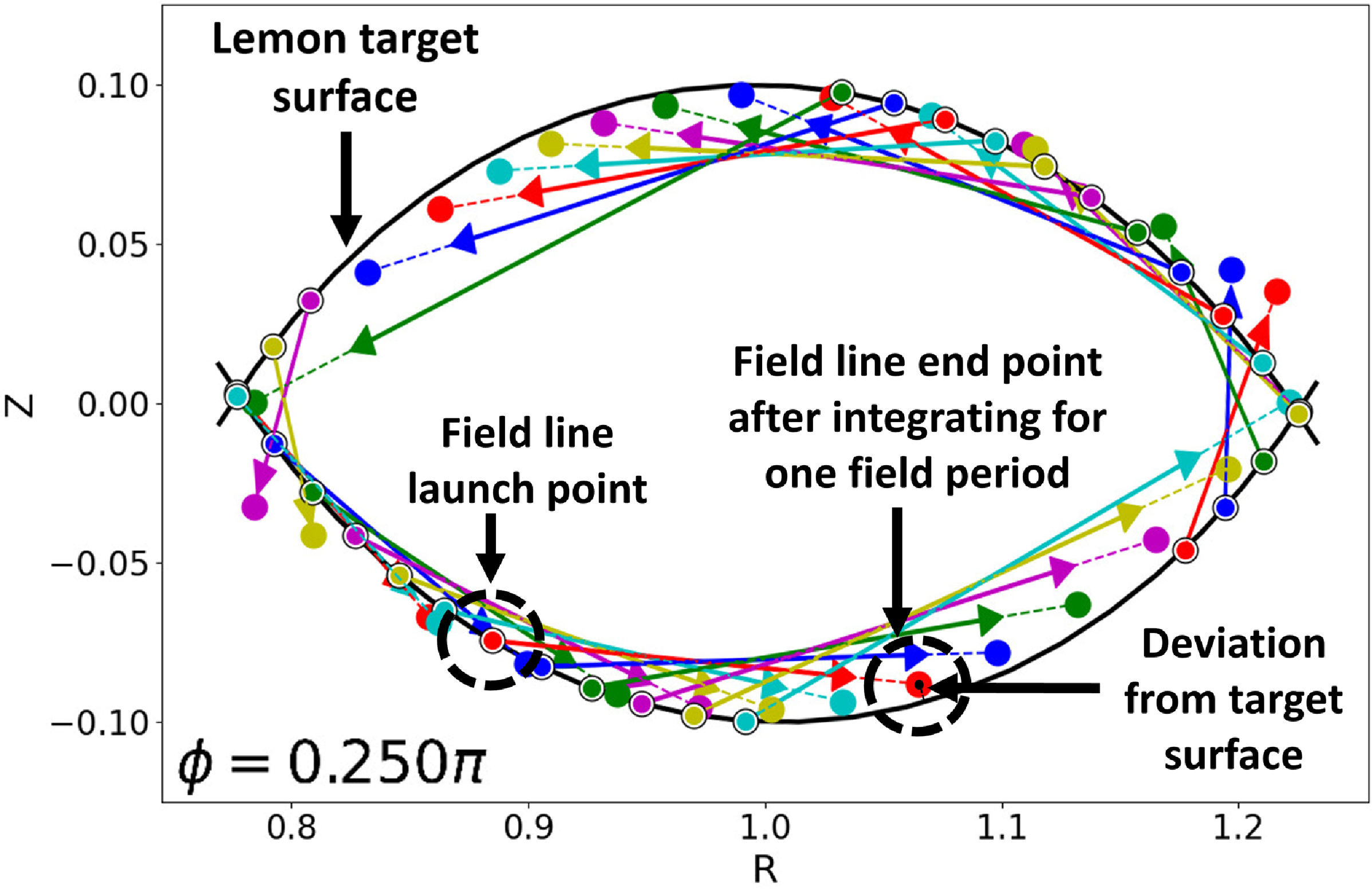
Illustration of manifold optimisation. Magnetic field lines are launched from starting points along the target surface (circles with black outline) and integrated one field period forward. The field-line endpoints (circles with no outline) are then used to compute surface deviation (2.6) which makes up the manifold optimisation penalty function.
The coordinate
 $\theta$
ranges over
$\theta$
ranges over
 $[-\theta _0,\theta _0]$
, defining the poloidal extent of the semicircles, and controlling the length by which the surfaces extend beyond their curve of intersection. For the parameters used here, the two halves of the surface extend a small amount beyond the intersection. This feature is likely not required; any surface with sharp corners can in principle be used to target the desired topology. The choice of
$[-\theta _0,\theta _0]$
, defining the poloidal extent of the semicircles, and controlling the length by which the surfaces extend beyond their curve of intersection. For the parameters used here, the two halves of the surface extend a small amount beyond the intersection. This feature is likely not required; any surface with sharp corners can in principle be used to target the desired topology. The choice of
 $ \theta _0$
strongly influences the resulting divertor geometry. For small values (
$ \theta _0$
strongly influences the resulting divertor geometry. For small values (
 $ \theta _0 \approx 0.6$
), the optimisation lacks sufficient incentive to form a well-defined separatrix, resulting in larger plasma volumes near the target surfaces. Conversely, excessively large
$ \theta _0 \approx 0.6$
), the optimisation lacks sufficient incentive to form a well-defined separatrix, resulting in larger plasma volumes near the target surfaces. Conversely, excessively large
 $ \theta _0$
over-constrains the problem by demanding low
$ \theta _0$
over-constrains the problem by demanding low
 $ B_{\mathrm{normal}}$
over an extended region, which degrades the average
$ B_{\mathrm{normal}}$
over an extended region, which degrades the average
 $ B_{\mathrm{normal}}$
performance and produces a diffuse or poorly defined separatrix.
$ B_{\mathrm{normal}}$
performance and produces a diffuse or poorly defined separatrix.
The parameters
 $d$
and
$d$
and
 $a$
control the angle of the surface intersection, although the dependence on these parameters was not studied here.
$a$
control the angle of the surface intersection, although the dependence on these parameters was not studied here.
A single lemon configuration is used throughout this work. The parameters used are:
 $R_0=1$
m,
$R_0=1$
m,
 $d=0.2$
m,
$d=0.2$
m,
 $a=0.3$
m,
$a=0.3$
m,
 $\theta _0=0.88$
,
$\theta _0=0.88$
,
 $\alpha _0=0$
,
$\alpha _0=0$
,
 $\alpha _1=\pi$
and
$\alpha _1=\pi$
and
 $n_{\!fp}=4$
. These parameters were chosen to ensure good divertor characteristics following coil optimisation. The value of
$n_{\!fp}=4$
. These parameters were chosen to ensure good divertor characteristics following coil optimisation. The value of
 $n_{\!fp}=4$
was chosen to coincide with field periodicity of another helical device, HSX.
$n_{\!fp}=4$
was chosen to coincide with field periodicity of another helical device, HSX.
2.2. Weighted squared flux
Typical
 $B_n$
minimisation was largely successful, although large
$B_n$
minimisation was largely successful, although large
 $B_n$
errors persisted near the sharp corners of the lemon. To remedy this, a weighted squared flux (WSF) was introduced to emphasise field accuracy near the sharp corners of the lemon, de-prioritising field accuracy at smoother parts of the target surface.
$B_n$
errors persisted near the sharp corners of the lemon. To remedy this, a weighted squared flux (WSF) was introduced to emphasise field accuracy near the sharp corners of the lemon, de-prioritising field accuracy at smoother parts of the target surface.
In the weighted approach, the quadratic flux integral was weighted inversely with distance from the corners of the lemon
 \begin{equation} f_w = \int\!{w}\left (\boldsymbol{x}\right ) \frac {\left (\boldsymbol{B}(\boldsymbol{x})\boldsymbol{\cdot }\boldsymbol{n}\right )^2}{B^2(\boldsymbol{x})} \, \text{d}A, \end{equation}
with
 \begin{equation} w\left (\boldsymbol{x}\right ) = \left ( 1-\frac {|\boldsymbol{x}-\boldsymbol{x}_{0}|}{d_{\max}} \right )^{p} , \end{equation}
where
 $\boldsymbol{x}$
is a location on the lemon surface,
$\boldsymbol{x}$
is a location on the lemon surface,
 $\boldsymbol{x}_{0}$
is location of the closest sharp corner,
$\boldsymbol{x}_{0}$
is location of the closest sharp corner,
 $d_{\max}$
is the maximum surface–intersection distance and
$d_{\max}$
is the maximum surface–intersection distance and
 $p$
is a coefficient controlling the locality of the weighting. As
$p$
is a coefficient controlling the locality of the weighting. As
 $p\to 0$
we revert to typical squared flux, while as
$p\to 0$
we revert to typical squared flux, while as
 $p \to \infty$
only points near the intersection are targeted.
$p \to \infty$
only points near the intersection are targeted.
An example of the weights on the surface is illustrated in figure 1.
2.3. Manifold optimisation
To further enhance the separatrix quality of the lemon, a novel optimisation technique, termed manifold optimisation, is employed. This method penalises the deviation of field lines originating on a target surface from that surface after tracing through one full field period. This method is intended to reduce chaos in the diverted field-line region.
Manifold optimisation is illustrated in figure 2. To begin, we use an array of points on the target surface for a single
 $\phi$
angle, here chosen to be
$\phi$
angle, here chosen to be
 $\phi _0=0.25\pi$
. Magnetic field lines started from these points are then traced for one field period, with integration ending at
$\phi _0=0.25\pi$
. Magnetic field lines started from these points are then traced for one field period, with integration ending at
 $\phi _{end}=\phi _0+(2\pi /n_{\!fp})$
. The endpoints of these field lines are then used to compute the deviation of the field lines at
$\phi _{end}=\phi _0+(2\pi /n_{\!fp})$
. The endpoints of these field lines are then used to compute the deviation of the field lines at
 $\phi _{end}$
from the target surface. The objective function to be minimised is
$\phi _{end}$
from the target surface. The objective function to be minimised is
 \begin{equation} J_{\text{maniopt}} = \sum _i \min |\boldsymbol{x}_i-\boldsymbol{S}|, \end{equation}
where
 $\boldsymbol{x}_i$
is the endpoint coordinate of the
$\boldsymbol{x}_i$
is the endpoint coordinate of the
 $i$
th traced field line and
$i$
th traced field line and
 $\boldsymbol{S}$
is the closest point on the target surface.
$\boldsymbol{S}$
is the closest point on the target surface.
In this work, manifold optimisation was used to improve the results of previously optimised coils. Indeed, manifold optimisation does not naively work with cold-start optimisation when the coils are initially planar: in a purely toroidal field, all field lines start back at their initial location after one field period, rendering 6 equal to 0.
An argument for why manifold optimisation may be more effective for chaos suppression than
 $B_n$
minimisation is that the latter treats resonant field errors as no different from non-resonant errors. Resonant errors typically result in large changes to magnetic field-line trajectories (for example, opening up magnetic islands) in response to small error fields. By directly targeting the properties of field-line trajectories, manifold optimisation may more efficiently eliminate the resonant field errors that stochasticise the edge magnetic field.
$B_n$
minimisation is that the latter treats resonant field errors as no different from non-resonant errors. Resonant errors typically result in large changes to magnetic field-line trajectories (for example, opening up magnetic islands) in response to small error fields. By directly targeting the properties of field-line trajectories, manifold optimisation may more efficiently eliminate the resonant field errors that stochasticise the edge magnetic field.
A curious observation is that the manifold optimisation objective only depends on the field-line locations at a single
 $\phi$
angle (and its field-period-symmetric location
$\phi$
angle (and its field-period-symmetric location
 $\phi _{end} = \phi _0 + 2\pi /n_{\!fp}$
). In effect, the magnetic field lines may move freely between
$\phi _{end} = \phi _0 + 2\pi /n_{\!fp}$
). In effect, the magnetic field lines may move freely between
 $\phi _0$
and
$\phi _0$
and
 $\phi _{end}$
, providing equilibrium flexibility. Manifold optimisation could perhaps be modified to also control the field-line locations at intermediate angles. This possibility is not explored further in this paper, although is an interesting topic for future work.
$\phi _{end}$
, providing equilibrium flexibility. Manifold optimisation could perhaps be modified to also control the field-line locations at intermediate angles. This possibility is not explored further in this paper, although is an interesting topic for future work.
This method was developed in SIMSOPT with PyOculus, a Python package for magnetic field topology analysis (Qu et al. Reference Smiet, Rais, Loizu and Davies2025).
2.4. Fixed-point analysis
When coils are optimised using the three methods above, some amount of chaos will remain around the separatrix. To assess the amount of this chaos we use a measure based on periodic field lines, known as fixed points of the Poincaré map. These fixed points can be classified as X-points, where neighbouring field lines converge or diverge in a hyperbolic structure (indicative of separatrix boundaries), or O-points, about which field lines rotate in elliptic orbits (often associated with magnetic islands). These points can be used to understand the characteristics of a stellarator divertor.
Greene’s residue quantifies the stability of these fixed points by analysing the behaviour of field lines in a neighbourhood of a periodic field line (Greene Reference Greene1979). A residue between 0 and 1 indicates an elliptic (stable) point, while values
 ${\lt}0$
or
${\lt}0$
or
 ${\gt}1$
imply a hyperbolic (unstable) point, potentially leading to chaotic regions. This metric has been used to optimise stellarator fields by targeting and minimising island widths, thereby reducing chaos (Hanson & Cary Reference Hanson and Cary1984).
${\gt}1$
imply a hyperbolic (unstable) point, potentially leading to chaotic regions. This metric has been used to optimise stellarator fields by targeting and minimising island widths, thereby reducing chaos (Hanson & Cary Reference Hanson and Cary1984).
Fixed-point analysis is used here to assess the degree of chaos achieved with each optimisation method. Following coil optimisation, X- and O-points near the sharp corner of the lemon were identified, and Greene’s residue of each resonance computed to quantify local stability. This provides a metric of the degree of chaos in the resulting magnetic fields.
Chaos is the result of island (or resonance) overlap. Each rotating corner of the lemon requires two field periods to complete one full poloidal rotation, corresponding to an
 $m=2$
resonance, where
$m=2$
resonance, where
 $m$
is the number of field period mappings necessary for a point to return to itself. Consequently, the resonances used for chaos quantification are those closest to the
$m$
is the number of field period mappings necessary for a point to return to itself. Consequently, the resonances used for chaos quantification are those closest to the
 $m = 2$
resonance. Fixed points with
$m = 2$
resonance. Fixed points with
 $m=2$
, 3 and 4 are found, and their Greene’s residue computed, to quantify the degree of chaos in each optimised coil configuration.
$m=2$
, 3 and 4 are found, and their Greene’s residue computed, to quantify the degree of chaos in each optimised coil configuration.
Greene’s residue of fixed points was also explored as an optimisation target to mitigate chaos. Although not detailed here, it proved to be overly sensitive to coil perturbations for effectively reducing chaos in the diverted field-line region, despite performing well near the core.
Another metric considered for chaos quantification was turnstile area (Smiet et al. Reference Smiet, Rais, Loizu and Davies2025), although this, too was found to be too sensitive to coil perturbations.
A major numerical challenge in this work arises from the extreme sensitivity of X-points in the divertor region, which severely limits the reliability of Greene’s residue as a direct optimisation objective. The Jacobian of the Poincaré map around these fixed points is typically large (of the order of
 $ 10^6$
), as evidenced by the Greene’s residue values themselves (table 1), indicating strong exponential divergence of nearby field lines (Boozer Reference Boozer2012; Boozer & Elder Reference Boozer and Elder2021) akin to a high Lyapunov exponent – even in regions that are not fully chaotic (i.e. where the dynamics depends on fewer than three variables). This rapid separation causes field-line integrations to become unreliable over extended lengths, as small numerical errors or perturbations from machine precision limits (e.g. in double-precision floating-point arithmetic) are amplified dramatically, rendering accurate long-term tracing impractical beyond a finite distance where tolerances are exceeded. This integration instability directly compounds errors in the fixed-point finder implemented in PyOculus (Qu et al. Reference Smiet, Rais, Loizu and Davies2025), which relies on a Newton-based root-finding method with a limited convergence basin; inaccuracies in the computed X-point location thus propagate and interact strongly with the large Jacobian, making the overall sensitivity highly nonlinear. Consequently, during optimisations, only extremely small coil perturbations can keep the fixed point within the method’s convergence region – rendering direct inclusion of Greene’s residue in the objective function computationally unstable. Attempts to impose stringent limits on coil variations proved impractical, as convergence remained too slow and error tolerances were still rapidly exceeded even with minute step sizes.
$ 10^6$
), as evidenced by the Greene’s residue values themselves (table 1), indicating strong exponential divergence of nearby field lines (Boozer Reference Boozer2012; Boozer & Elder Reference Boozer and Elder2021) akin to a high Lyapunov exponent – even in regions that are not fully chaotic (i.e. where the dynamics depends on fewer than three variables). This rapid separation causes field-line integrations to become unreliable over extended lengths, as small numerical errors or perturbations from machine precision limits (e.g. in double-precision floating-point arithmetic) are amplified dramatically, rendering accurate long-term tracing impractical beyond a finite distance where tolerances are exceeded. This integration instability directly compounds errors in the fixed-point finder implemented in PyOculus (Qu et al. Reference Smiet, Rais, Loizu and Davies2025), which relies on a Newton-based root-finding method with a limited convergence basin; inaccuracies in the computed X-point location thus propagate and interact strongly with the large Jacobian, making the overall sensitivity highly nonlinear. Consequently, during optimisations, only extremely small coil perturbations can keep the fixed point within the method’s convergence region – rendering direct inclusion of Greene’s residue in the objective function computationally unstable. Attempts to impose stringent limits on coil variations proved impractical, as convergence remained too slow and error tolerances were still rapidly exceeded even with minute step sizes.
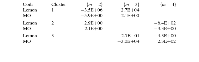
Greene’s residues of resonant fixed-point clusters near the divertor region (see figure 6). Only lemon and MO configurations are shown to illustrate the chaos suppression achieved through manifold optimisation.

3. Results
The result of straightforward
 $B_n$
minimisation on the rotating lemon may be seen in figures 3 and 4. The coil set pictured here, hereafter referred to as the lemon coil set, is used as our baseline result for comparison with other methods. It includes four unique coil shapes per half-period, for 32 coils in total.
$B_n$
minimisation on the rotating lemon may be seen in figures 3 and 4. The coil set pictured here, hereafter referred to as the lemon coil set, is used as our baseline result for comparison with other methods. It includes four unique coil shapes per half-period, for 32 coils in total.
Three-dimensional rendering of the rotating lemon divertor structure. The divertor legs are well separated and non-chaotic.

(a) Coil set of the rotating lemon after typical
 $B_n$
minimisation with field lines shown. (b) Poincaré sections for the lemon coil set at several toroidal angles.
$B_n$
minimisation with field lines shown. (b) Poincaré sections for the lemon coil set at several toroidal angles.

Poincaré sections of (a) the lemon, (c) manifold-optimised, (d) WSF coil sets and (b) the LHD divertor for comparison. Panel (b) is reproduced from Feng et al. (2009). All Poincaré plots for the lemon coil set were generated using field lines launched from consistent initial conditions in the core region (points inside the last closed flux surface). In the diverted region, initial conditions are largely consistent across plots, although minor adjustments were necessary due to the unique divertor configuration produced by each coil set; these small variations ensure representative sampling of the edge topology without altering the overall qualitative comparison.

The diverted field-line properties of the lemon coil set are reminiscent of a standard tokamak X-point divertor. As can be seen in figures 3 and 4, the divertor legs fan out crisply from the sharp edge of the lemon. That is, field lines just outside the lemon boundary flow to the X-lines and turn a corner, then move far from the plasma. Just as in LHD, baffles could be placed close to the divertor legs, with a thin gap around the X-lines for outflow from the plasma. This closed geometry would prevent neutrals and impurities originating from the divertor target plates from having a line of sight to the core, concentrating neutrals for efficient pumping.
When compared with the LHD divertor, reproduced here in figure 5(b), the lemon’s diverted field-line region (figure 4 b) is considerably less chaotic. Field-line connection lengths were calculated for the configurations illustrated in figures 5(a), 5(c) and 5(d). These values align closely with those of the LHD’s diverted field lines, reaching up to 3 m in length for the WSF coil set and 1–2 m for the lemon and Manifold-Optimized coil sets. By contrast, the LHD’s diverted field lines along the divertor legs measure approximately 2 m.
The lemon equilibrium was chosen to use
 $n_{\!fp}=4$
field periods for similarity to HSX, a quasi-helical device. However, it should be noted that its lower field period count compared with LHD’s
$n_{\!fp}=4$
field periods for similarity to HSX, a quasi-helical device. However, it should be noted that its lower field period count compared with LHD’s
 $n_{\!fp}=10$
may result in a sparser distribution of resonant surfaces for similar aspect ratios, potentially leading to reduced field-line chaos from fewer overlapping magnetic islands when compared with LHD’s divertor.
$n_{\!fp}=10$
may result in a sparser distribution of resonant surfaces for similar aspect ratios, potentially leading to reduced field-line chaos from fewer overlapping magnetic islands when compared with LHD’s divertor.
The lemon coil set has some distinctive differences compared with typical modular coils. At its widest point, each coil has a section which runs nearly parallel to the sharp edge of the lemon. This appears to be an emulation of helical coils by the modular coils.
A coil set generated using the WSF method, hereafter referred to as the WSF coil set, may be seen in figure 1, with the Poincaré section appearing in figure 5(d). The WSF coil set was optimised using randomised sampling over the weights and thresholds of (2.1) and (2.6). The WSF coil set features improved coil engineering metrics, as shown in table 2 at the expense of higher separatrix chaos. Indeed, the diverted field-line region of the WSF coil set is similar to that of LHD, figure 5(b). Further, the lemon target shape is not as closely matched for the WSF coil set, although this is not surprising as the WSF method emphasises field correctness near the sharp corners. Overall, the WSF coil set produces an LHD-like divertor with more engineering-friendly modular coils.
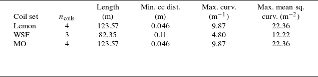
Engineering performance comparison of the coil sets across five metrics: number of coils per half-field period, total coil set length (m), minimum coil–coil distance (m), maximum coil curvature (m
 $^{-1}$
) and maximum coil mean squared curvature (m
$^{-1}$
) and maximum coil mean squared curvature (m
 $^{-2}$
).
$^{-2}$
).
Locations of selected fixed points for quantifying divertor chaos for the lemon coil sets, grouped into clusters by spatial proximity. Cluster 1 (primary resonance branch) includes
 $m=2$
and
$m=2$
and
 $m=3$
fixed points at
$m=3$
fixed points at
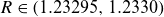 $R \in (1.23295, 1.2330)$
and
$R \in (1.23295, 1.2330)$
and
 $Z = 0$
. Cluster 2 comprises
$Z = 0$
. Cluster 2 comprises
 $m=2$
and
$m=2$
and
 $4$
fixed points at
$4$
fixed points at
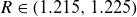 $R \in (1.215, 1.225)$
and
$R \in (1.215, 1.225)$
and
 $Z = 0$
. Cluster 3 contains
$Z = 0$
. Cluster 3 contains
 $m=3$
and
$m=3$
and
 $4$
periodic fixed points at
$4$
periodic fixed points at
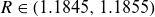 $R \in (1.1845, 1.1855)$
and
$R \in (1.1845, 1.1855)$
and
 $Z \in (-0.0344, -0.0350)$
. Positions vary slightly across coil configurations. Greene’s residues, assessing stability and chaotic behaviour, appear in table 1.
$Z \in (-0.0344, -0.0350)$
. Positions vary slightly across coil configurations. Greene’s residues, assessing stability and chaotic behaviour, appear in table 1.

A coil set generated using manifold optimisation, hereafter referred to as the MO coil set, is not shown here as it is visually indistinguishable from the original lemon coils, with differences at the mm level. The MO coil set was produced by applying manifold optimisation with the lemon coil set as an initial condition. A Poincaré section of the MO coil set may be seen in figure 5(c). The MO coil set exhibits reduced chaos in the separatrix according to the residues in table 1, albeit with a slight stochastic width (orange points in figure 5(c)) resulting from the divertor manifold optimisation. This could potentially be treated by a combined optimisation with Greene’s residue, although this was not pursued in this work.
Coil complexity metrics are compared in table 2. The initial lemon coil set, figure 3, has higher curvature and lower coil–coil clearances. The WSF method, in contrast, relaxes each considered coil engineering penalty by a factor of two and uses only three coils per half-field period. The MO coil set is virtually identical to the lemon coil set.
Greene’s residues for fixed points in the diverted field-line region are shown in table 1, and their locations are shown in figure 6. The
 $m=2$
fixed point is the main resonance of the lemon’s divertor concept as the corners rotate with
$m=2$
fixed point is the main resonance of the lemon’s divertor concept as the corners rotate with
 $m=2$
periodicity. There is an additional
$m=2$
periodicity. There is an additional
 $m=3$
fixed point which lies within 10
$m=3$
fixed point which lies within 10
 $\mu$
m of the
$\mu$
m of the
 $m=2$
fixed point. These two fixed points, hereafter referred to as the main fixed points, are inextricably linked to the chaos of the diverted field lines. On the other hand, the fixed points of cluster 2 and cluster 3 from figure 6 are linked to chaos both in the diverted field-line region and near the last closed flux surface. Fixed points in clusters 2 and 3 are referred to as the secondary fixed points.
$m=2$
fixed point. These two fixed points, hereafter referred to as the main fixed points, are inextricably linked to the chaos of the diverted field lines. On the other hand, the fixed points of cluster 2 and cluster 3 from figure 6 are linked to chaos both in the diverted field-line region and near the last closed flux surface. Fixed points in clusters 2 and 3 are referred to as the secondary fixed points.
For the lemon coil set, the primary fixed points exhibit large Greene’s residues, while secondary fixed points show small values. Consequently, field lines in the divertor region transit rapidly. Despite this, the separatrix remains largely free of chaos.
For the MO coil set, residues of the primary fixed points are reduced by several orders of magnitude compared with the lemon case (table 1), resulting in a less chaotic divertor region. However, the secondary fixed points have larger residues, increasing stochasticity near the last closed flux surface.
The simple fixed-point analysis used in table 1 fails to fully capture the chaos of the WSF coil set, as multiple overlapping resonances contribute significantly to the stochastic layer.
4. Discussion
In this work we have presented a new option for a stellarator divertor: a helical divertor produced with optimised modular coils. This solution combines the principal advantage of the helical divertor – the possibility of tight baffling to confine neutrals in front of the pumps – with the advantages of modular coils: the ability to wind coils in a factory off site and transport them to the final location rather than wind them on the vacuum chamber. We also demonstrated that the high level of chaos around the separatrix of LHD’s divertor is not necessary in a helical divertor – in fact, helical divertors can be found with much reduced chaos. The key to the method was performing standard modular coil optimisation using a target plasma surface with a toroidally continuous sharp edge.
In this paper we also presented manifold optimisation, a new objective function which can be incorporated in coil design. Manifold optimisation may have the potential to produce separatrices with low chaos, although in the example here the resulting configuration was very sensitive to coil perturbations. Nonetheless, it represents a new option for reducing stochasticity and is computational efficient.
The manifold-optimised coil set’s sensitivity to perturbations underscores a fundamental challenge in stellarator divertor design. Because diverted field lines must pass close to the diverting coils, their separatrices become inherently fragile. It remains to be shown that a divertor robust to coil perturbations can be realised. In the computational design of stellarator divertors, this fragility frequently drives field-line tracing to the limits of numerical precision.
Additional work is required to develop this divertor concept. Perhaps most significantly, the target plasma surface in this work was not optimised for good confinement or stability. Such optimisation of the plasma boundary has previously been performed using equilibrium codes with a Fourier description of the boundary, resulting in a smooth plasma surface. Therefore a key question is how to optimise plasma boundary shapes with both good core physics properties and sharp edges. Gaur et al. (Reference Gaur, Panici, Elder, Landreman, Unalmis, Elmacioglu, Dudt, Conlin and Kolemen2025) presented an approach to this question, but the edge field behaviour was significantly different from the sharp separatrix shown here, perhaps because the boundaries in Gaur et al. (Reference Gaur, Panici, Elder, Landreman, Unalmis, Elmacioglu, Dudt, Conlin and Kolemen2025) did not have a truly discontinuous normal. A related question is whether modern quasisymmetric (QS) or quasi-isodynamic (QI) plasma geometries are compatible with the helical divertor here. Typically QS and QI plasma boundaries have a high-curvature ridge which extends toroidally for approximately one field period, but not around the entire torus. Thus it remains to be seen whether a helical divertor like the one here can be generated for a QS or QI geometry.
Further development of this divertor concept will also require more sophisticated modelling to study many topics. These include the width of the heat flux layer, behaviour of neutrals in the presence with realistic wall and baffle geometry, sensitivity to plasma beta and detachment access.
Another question for future work is the optimal level of chaos in the separatrix. The chaos in LHD’s separatrix has been suggested as a reason it has been hard to achieve stable detachment (Feng et al. Reference Feng, Kobayashi, Lunt and Reiter2011), suggesting that reduced chaos would be beneficial. On the other hand, chaos in the separatrix likely increases the width of the heat flux layer, reducing the peak heat flux on the divertor plates. Research is required to determine the optimal balance between these considerations.
Acknowledgements
T.E. was supported by the U.S. Department of Energy Fusion Energy Sciences Postdoctoral Research Program administered by the Oak Ridge Institute for Science and Education (ORISE) for the DOE. ORISE is managed by Oak Ridge Associated Universities (ORAU) under DOE contract number DE-SC0014664. This work was also supported by the U.S. Department of Energy, Office of Science, Office of Fusion Energy Sciences under Award DE-FG02-93ER54197.
Editor Per Helander thanks the referees for their advice in evaluating this article.
Data availability statement
Data are available on request from the authors.
Declaration of interests
The authors declare no competing interests.


 Open access