


1 Introduction
Dual-pulse lasers (DPLs) with vastly different pulse widths, especially integrating femtosecond (fs) or picosecond (ps) ultra-short pulses (USPs) with nanosecond (ns) pulses (NPs), exhibit superior acquisition rates, spectral resolution and signal-to-noise characteristics in spectroscopic and metrological applications[ Reference Coddington, Newbury and Swann1– Reference Coddington, Swann, Nenadovic and Newbury5]. Furthermore, the unique ability to simultaneously exploit both non-thermal (‘cold’) and thermal (‘hot’) processing mechanisms facilitates transformative advances in applications such as laser-induced breakdown spectroscopy and high-precision material processing, leading to improvements in spatial resolution and a reduction in detection thresholds[ Reference Lu, Mao, Zheng and Russo6, Reference Kerse, Kalaycıoğlu, Elahi, Çetin, Kesim, Akçaalan, Yavaş, Aşık, Öktem and Hoogland7]. Thus, the DPL, as a pioneering technological platform, can effectively bridge the realms of ultrafast photonics and high-intensity material interactions[ Reference Wu, Young and Li8]. Generally, the realization of DPLs relies on two fundamental approaches: intrinsic dual-pulse generation within a single laser cavity and external synchronization of parallel two-laser systems[ Reference Lu, Mao, Zheng and Russo6, Reference Mizuno, Nakajima, Hata, Tsuda, Asahara, Kato, Minamikawa, Yasui and Minoshima9, Reference Li, Xing, Kwon, Xie, Prakash, Kim and Huang10].
DPL generation within a single laser cavity has been extensively studied, primarily via three approaches: temporal multiplexing, spatial multiplexing and polarization multiplexing[ Reference Mizuno, Nakajima, Hata, Tsuda, Asahara, Kato, Minamikawa, Yasui and Minoshima9– Reference Yang, Smith, Petersen and Bang12]. For instance, two laser beams generated from a bidirectional configuration exhibit output powers of 50 and 72 mW at 45.9 MHz, but with a 140 Hz repetition rate offset[ Reference Li, Xing, Kwon, Xie, Prakash, Kim and Huang10]. The polarization-multiplexed dual-pulse mode-locked fiber laser also achieved pulse widths of 1.53 and 1.47 ps, respectively, and repetition rate differences in the range of 110–250 Hz[ Reference Cuevas, Kbashi, Stoliarov and Sergeyev13]. However, these kinds of fiber-based DPL systems face critical limitations: (1) restricted pulse width tunability, confined to fs-to-ps pulse widths; (2) limited temporal separation capabilities, typically operating at the ps level; and (3) significant nonlinearity constraints, as soliton mode-locked fiber lasers inherently suffer from excessive nonlinear phase accumulation[ Reference Mizuno, Nakajima, Hata, Tsuda, Asahara, Kato, Minamikawa, Yasui and Minoshima9, Reference Qin, Cromey, Batjargal and Kieu14].
In solid-state lasers, DPLs have been demonstrated using spatial and polarization multiplexing techniques, achieving MHz repetition rates and watt-level output powers[ Reference Galtier, Pivard, Morville and Rairoux15– Reference Modsching, Drs, Brochard, Fischer, Schilt, Wittwer and Südmeyer19]. For instance, spatial multiplexing has enabled dual-pulse mode-locking at 80 MHz, yielding a single-beam power exceeding 2.4 W with pulse widths below 140 fs[ Reference Pupeikis, Willenberg, Camenzind, Benayad, Camy, Phillips and Keller18]. Separately, polarization splitting in thin-disk lasers generates asynchronous pulse trains with pulse widths of 240 fs, average powers of 6 and 8 W per train and repetition rates of 97 MHz at 1030 nm[ Reference Modsching, Drs, Brochard, Fischer, Schilt, Wittwer and Südmeyer19]. Despite these advances, such implementations typically produce fs or ps dual pulses with fixed, small temporal separations dictated by optical path difference, while suffering from limited pulse energy and inflexible power ratio control. These constraints – particularly the inability to independently adjust pulse parameters – significantly restrict their applicability in precision laser machining.
In external synchronization of parallel laser systems, the current industrial-standard parallel dual-laser configuration provides independent parameter control but suffers from inherent timing jitter, beam divergence and system complexity[ Reference Lu, Mao, Zheng and Russo6]. Consequently, these limitations highlight the critical need for innovative approaches to achieve high-power, tunable dual pulse with ps/ns pulse widths generation based on a single cavity.
To address these issues, this study presents a DPL generation scheme based on independent temporal modulation, which enables a flexible tunable pulse width and temporal interval. Through time-domain stretching of the broadband seed pulses, synchronous DPLs with pulse widths of 5.6 ps and 0.42 ns are successfully achieved based on a single cavity. Precision control of temporal intervals is achieved via optical-delay adjustment, providing ps-level synchronization accuracy, from –4 to 12.5 ns. Employing an acoustic optical modulator (AOM), continuous tuning of repetition rates across a wide range from 100 kHz to 32 MHz is realized. Furthermore, a master oscillator power amplifier (MOPA) validated system demonstrates a maximum output power of 1092 W (16 MHz), producing 15.9 ps and 0.44 ns pulses – establishing a high-power DPL source. The proposed single-cavity based DPL generation scheme overcomes traditional limits, enabling synergistic USP/NP interactions while solving DPL synchronization/complexity issues for precision applications.
2 Experiment setup
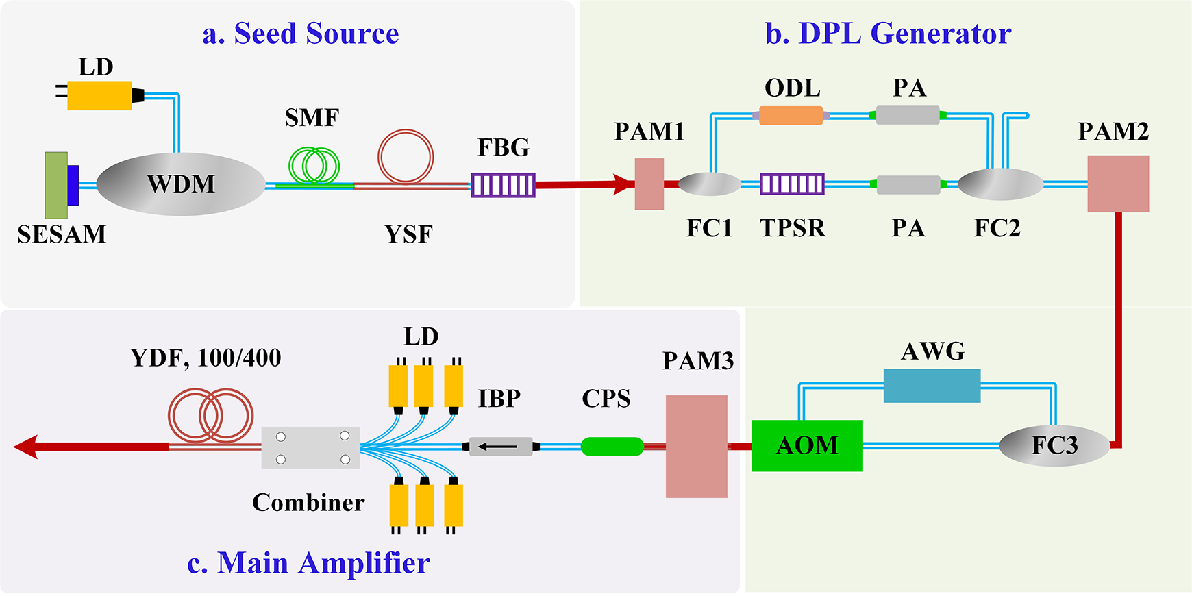
The high-power all-fiber DPL system, as shown in Figure 1, comprises three principal parts: a passively mode-locked seed source, a DPL generator and a main amplifier. The seed source consists of a 300-mW 976 nm laser diode (LD), a wavelength division multiplexer (WDM), a semiconductor saturable absorber mirror (SESAM), a piece of 0.5 m Yb3+-doped single-mode fiber and a 1064 nm fiber Bragg grating (FBG) with 30% reflectivity and –3 dB spectral bandwidth of 1 nm.
Schematic of the high-power DPL. LD, laser diode; YSF, Yb3+-doped single-mode fiber; SMF, single-mode fiber; SESAM, semiconductor saturable absorber mirror; FBG, fiber Bragg grating; WDM, wavelength division multiplexer; PAM, pre-amplifier; FC, fused coupler; ODL, optical-delay line; PA, power attenuator; TPSR, tunable pulse stretcher (PowerSpectrum™ TPSR, TeraXion); AOM, acousto-optic modulator; AWG, arbitrary waveform generator; CPS, cladding power stripper; IBP, isolator with a bandpass filter; YDF, Yb3+-doped fiber.

The seed pulse is then injected into the DPL generator. In particular, it first passes through a pre-amplifier (PAM1) for power enhancement and then is divided into two beams via a fused coupler (FC1). One beam is temporally broadened first owing to a tunable pulse stretcher (TPSR) and then propagates though a power attenuator (PA). The TPSR is a compact, robust and cost-effective chirped fiber Bragg grating (CFBG) to control pulse durations. Another beam propagates through an optical-delay line (ODL) and another PA. Then, the two beams are coupled into one though the 2×2 FC2, amplified by PAM2. The repetition rate of the DPL is controlled by an AOM and an arbitrary waveform generator (AWG).
The main amplifier comprises PAM3 and a multi-mode amplifier that consists of a 4 m extra-large-mode-area 100/400 μm Yb3+-doped fiber, six 300 W 976 nm LDs and a (6 + 1) × 1 multi-mode pump/signal combiner. A cladding power stripper (CPS) is used after the pre-amplifier stage to strip residual pump light, while an isolator with a bandpass filter (IBP) is placed between stages to isolate back-reflected light and filter out amplified spontaneous emission (ASE) from the preceding stage, ensuring spectral purity for the next amplification stage. All optical components are mounted on water-cooled heat sinks to maintain thermal stability.
The pulse sequence in our experiment is measured with a 5 GHz bandwidth photodetector (Thorlabs, DET08CL), a 4 GHz bandwidth oscilloscope (Agilent Technologies, DSO7104B), an autocorrelator (APE, SM-2000) and a spectrometer (Yokogawa, AQ6370D).
3 Results and discussion
3.1 Tunable DPL
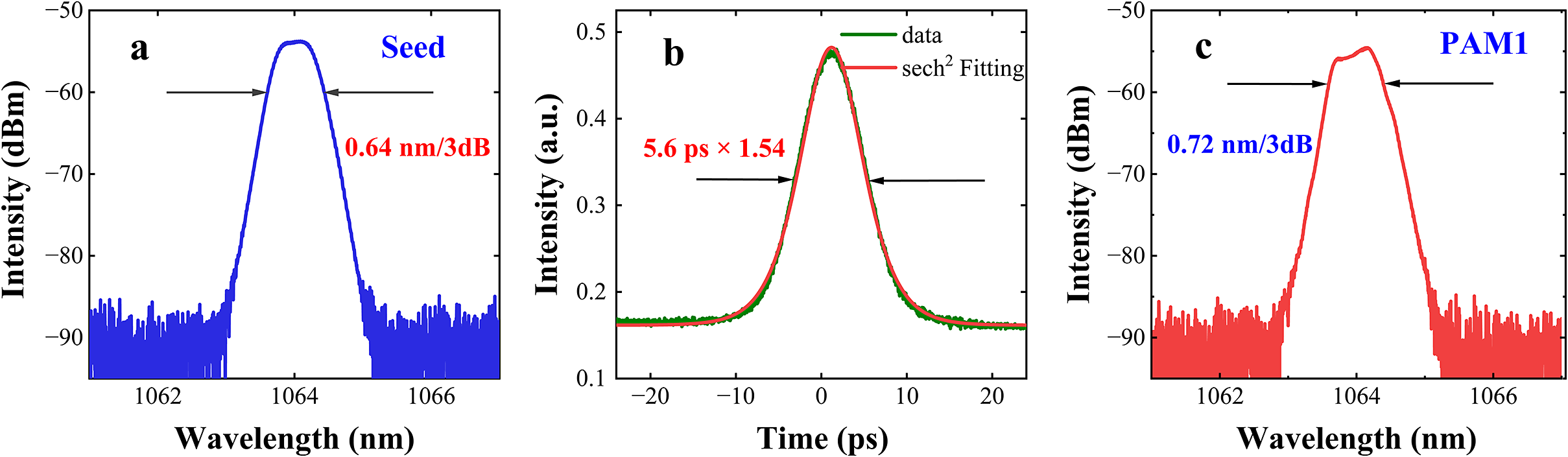
To achieve DPL operation in the USP and NP, a mode-locked fiber oscillator is designed as shown in Figure 1(a). The maximum output power of the mode-locked pulse is 3.2 mW with a repetition rate of 32 MHz. The –3 dB bandwidth $\Delta {\lambda}_\mathrm{pulse}$
and the pulse width, as shown in Figures 2(a) and 2(b), are 0.64 nm and 5.6 ps, respectively, confirming USP generation.
$\Delta {\lambda}_\mathrm{pulse}$
and the pulse width, as shown in Figures 2(a) and 2(b), are 0.64 nm and 5.6 ps, respectively, confirming USP generation.
(a) Optical spectrum and (b) autocorrelation trace of the mode-locked seed pulse. (c) Optical spectrum of the laser pulse after PAM1.

Since the generation of the ps/ns DPL relies on first generating the NP, the next step is to generate the NP. As shown Figure 1(b), the USP passes through the 1×2 FC1 with a splitting ratio of 4:6, with 60% of the power coupled into the TPSR for temporal broadening. However, an insertion loss can also be introduced by the TPSR. Therefore, PAM1 is introduced before FC1 to enhance the power and compensate for the loss. The amplified pulse, as shown in Figure 2(c), demonstrates a –3 dB bandwidth of 0.72 nm under 10 mW output power.
The temporal broadening $\Delta {\tau}_{\mathrm{total}}$
induced by the TPSR can be expressed as follows:
$\Delta {\tau}_{\mathrm{total}}$
induced by the TPSR can be expressed as follows:
 $$\begin{align*}\Delta {\tau}_{\mathrm{total}}\approx \mathrm{GVD}\cdot \Delta {\lambda}_\mathrm{pulse},\end{align*}$$
where GVD is the group velocity dispersion introduced by the TPSR and $\Delta {\lambda}_\mathrm{pulse}$
is the input pulse bandwidth[
Reference Kashyap20]. In our experiment, the GVD can be continuously adjusted between 500 and 720 ps/nm.
$\Delta {\lambda}_\mathrm{pulse}$
is the input pulse bandwidth[
Reference Kashyap20]. In our experiment, the GVD can be continuously adjusted between 500 and 720 ps/nm.
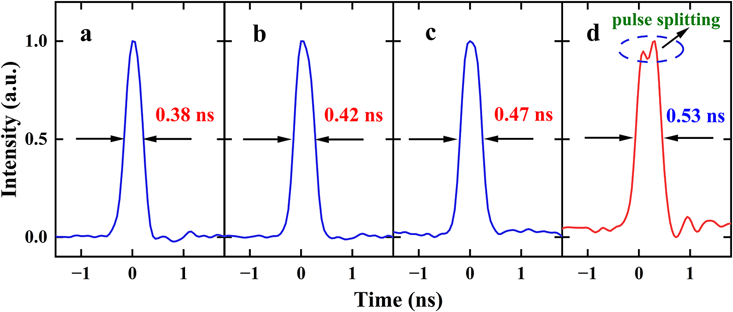
In particular, when the GVD is set to 500, 600 and 650 ps/nm, the corresponding stretched pulse widths are 0.38, 0.42 and 0.47 ns, respectively, as shown in Figures 3(a)–3(c). It can be seen that this dispersion enables controlled temporal broadening of the USP while nearly preserving its temporal profile. Further increasing the GVD to 720 ps/nm results in pulse broadening to 0.53 ns, as shown in Figure 3(d). However, pulse splitting is also observed, demonstrating a deterioration in the pulse temporal profile. To maintain the single-pulse operation, the stretched pulse with duration of 0.42 ns at GVD = 600 ps/nm is adopted for the subsequent amplification. Subsequently, the USP and the NP are combined using a 2×2 FC, generating a DPL sequence.
Typical pulse widths of the USP with (a) 500, (b) 600, (c) 650 and (d) 720 ps/nm GVD introduced by the TPSR.

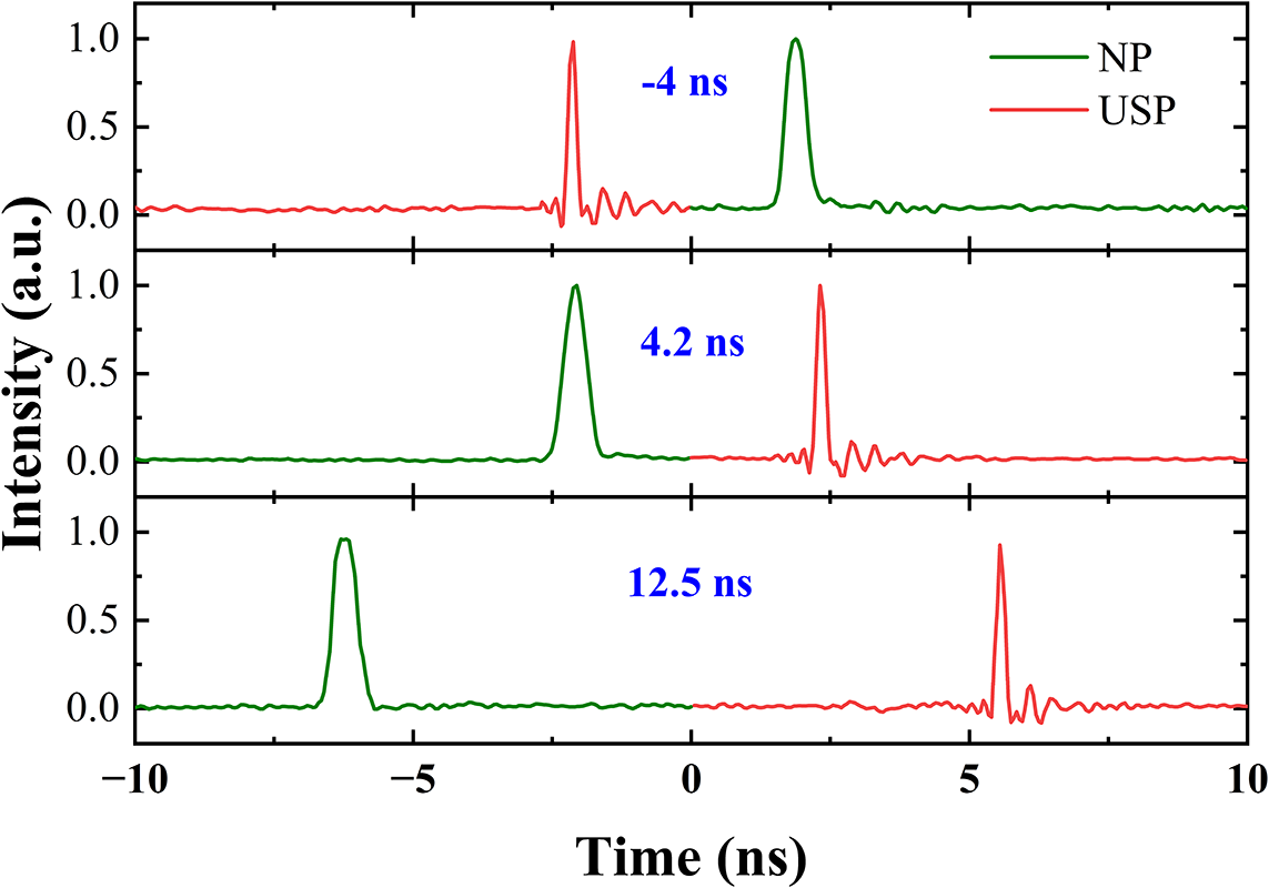
The temporal interval is another important factor for improving the accuracy in the laser processing applications. Thus, except for the pulse width difference, the adjustment of the temporal interval between the two pulses is also desired. Meanwhile, the tunable temporal interval is primarily achieved by changing the optical path difference between the NP and USP sequences, as shown in Figure 1(b). In particular, an ODL (1.2 ns with 1 ps adjustment accuracy) is inserted into the USP path. Coarse adjustment of the temporal interval, typically with ns precision, is accomplished by varying the fiber length, while fine-tuning at the ps-level resolution is achieved via the ODL. This dual-adjustment mechanism enables a broad range of temporal interval modulation with a high resolution. The maximum tunable temporal interval ranges from –15.6 to +15.6 ns, which is determined by the pulse interval of the seed source. The positive value indicates that the NP precedes the USP, whereas a negative value signifies that the USP leads the NP. The temporal interval range cannot be further enlarged constrained by the repetition rate of the seed source. Figure 4(a) shows temporal profiles of the dual-pulse structure with intervals of –4, 4.2 and 12.5 ns, illustrating the feasibility of flexible control. Furthermore, the repetition rate of the DPL can be tuned from 100 kHz to 32 MHz by varying the settings of the AWG.
DPLs with temporal intervals of –4, 4.2 and 12.5 ns, respectively.

In practical applications, active control of the inter-pulse power ratio is essential, since their divergent nonlinear responses induce efficiency variations in energy extraction, mandating individualized pulse optimization[ Reference Ahmed, Iqbal and Baig21]. By adjusting the PA, precise control of the dual-pulse power ratio is achieved while simultaneously enabling the generation of fixed pulse width pulses. Furthermore, independent adjustments of the ODL and PA allow the precise and flexible modulation of both the temporal interval and power ratio. Thus, it can be seen from the above results that the proposed configuration enables the realization of an all-fiber DPL featuring four key tunable characteristics: (1) pulse widths; (2) temporal intervals; (3) power ratios; (4) repetition rates. Notably, since both pulse trains originate from the same seed laser, the system maintains intrinsic coherence without an additional passive synchronous control device. This integrated architecture makes it particularly suitable for subsequent amplification, while serving as a versatile optical source for various applications requiring tailored DPL outputs.
3.2 Main amplifier
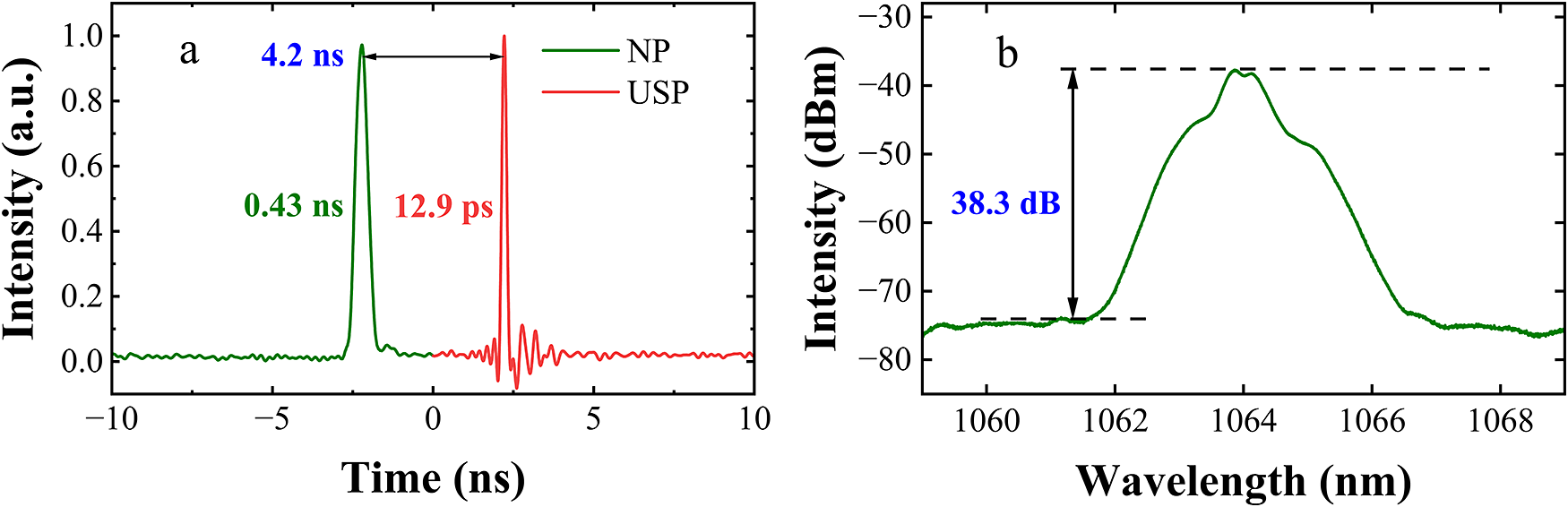
Applications such as nano/micro fabrication demand high-power lasers to meet rigorous processing requirements[ Reference Yang, Wei, Ma, Song, Ma, Zhao, Huang, Zhang, Yang and Wang22– Reference Li, Yu, Zou, He, Ning, Wu, Chen and Lin25]. Thus, in this part, the amplification properties of the proposed DPL are investigated. A seed source operating at 32 MHz with an average power of 307 mW has been chosen for subsequent pulse selection and amplification. The power ratio of a DPL output, with 12.9 ps and 0.43 ns pulse widths separated by 4.2 ns temporal intervals, is approximately 1:1 and is preserved for subsequent amplification studies. Figure 5 presents the temporal profile and amplified spectrum of the DPL. The signal-to-noise ratio (SNR) of the DPL is 38.3 dB, as shown in Figure 5(b). After the two pulses are coupled, PAM3 is cascaded with a multi-mode fiber amplifier to provide amplification. After PAM3, the powers of the DPL are quantified as follows: 5.13 W at 16 MHz, 4.96 W at 6.4 MHz and 4.79 W at 3.2 MHz.
(a) The temporal profile and (b) the corresponding spectrum of the DPL.

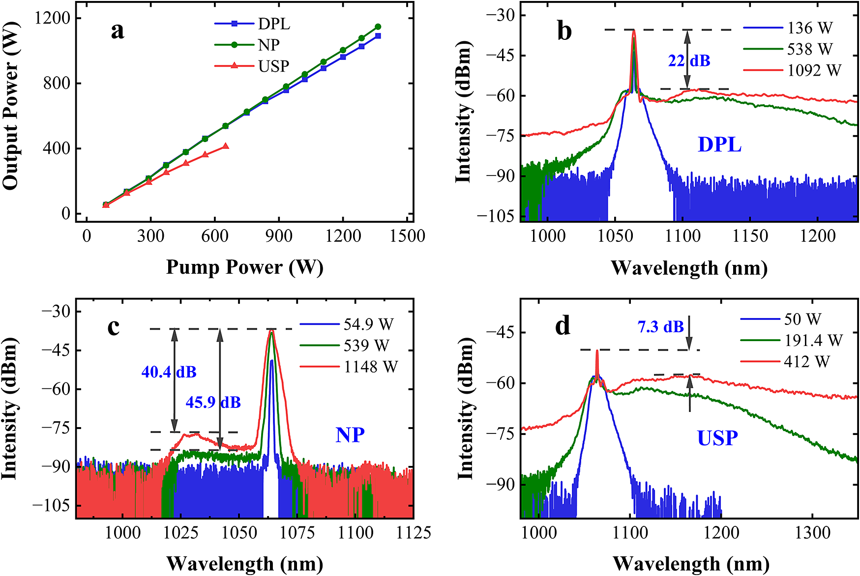
Figure 6 presents amplified powers and corresponding spectra for DPL operation, NP operation and USP operation, at a repetition rate of 16 MHz. The DPL (blue line) achieves a maximum output power of 1092 W with an optical-to-optical conversion efficiency (η) of 80%. Similarly, the NP (green line) reaches a maximum output power of 1148 W at η = 84.1%. In contrast, the USP (red line) delivers a comparatively low maximum output power of 412 W, with a conversion efficiency of 63.4%. This limitation is mainly due to the onset of pulse instabilities at high pump power levels, which can lead to detrimental effects, including irreversible optical fiber damage.
(a) The output power of the main amplifier versus pump power under DPL, NP and USP operations. (b) Spectra of DPL operation under 136, 538 and 1092 W output. (c) Spectra of NP operation under 54.9, 539 and 1148 W output. (d) Spectra of USP operation under 50, 191.4 and 412 W output.

Comparative analysis reveals significant divergence in amplification characteristics across pulse duration regimes. The USP exhibits efficiency saturation when pulse energy exceeds 7.75 μJ (124 W@16 MHz), manifested as progressively decreasing amplification efficiency. In contrast, both NP and DPL operations maintain linear power scaling behavior. Notably, when DPL pulse energy exceeds 38.75 μJ (620 W@16 MHz), the DPL exhibits reduced amplification efficiency compared to the NP, which may be due to the influence of the USP of the DPL. A comparative spectral analysis of the amplified pulses is conducted to elucidate the underlying physical mechanisms.
Figures 6(b)–6(d) systematically investigate the spectral evolution in the main amplifier under three different operations. Notably, Figure 6(b) reveals severe spectral broadening under DPL operation at 1092 W, primarily driven by strong nonlinear effects, particularly stimulated Raman scattering (SRS). The SNR decreases to only about 22 dB. In contrast, Figure 6(c) demonstrates that the NP operation maintains an exceptional SNR of 40.4 dB even at a higher power of 1148 W, while ASE dominates the noise profile. This result highlights the NP’s remarkable resistance to nonlinear spectral distortion. As for the USP, it exhibits extreme spectral broadening, shown in Figure 6(d) under 412 W operation, with SRS drastically reducing the SNR to just 7.3 dB. Critically, comparative analysis demonstrates that at 1 kW output power, the DPL exhibits significantly suppressed spectral broadening relative to the USP – an effect arising from the NP component, which endows the DPL with intermediate spectral characteristics between the NP and USP.
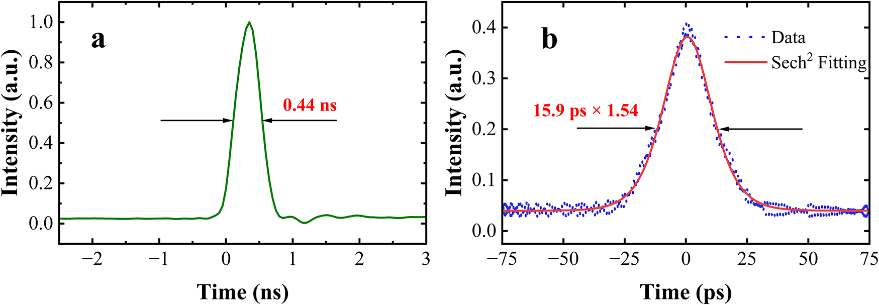
The pulse width of the NP measured by an oscilloscope is 0.44 ns at an output power of 1148 W, as illustrated in Figure 7(a). Meanwhile, the pulse width of the USP measured by an autocorrelator is 15.9 ps at an output power of 400 W, as shown in Figure 7(b). Under increasing output power, the NP demonstrates remarkable pulse width stability (0.42–0.44 ns), while the USP suffers from substantial pulse width broadening (5.6–15.9 ps).
(a) Pulse width of the NP recorded using an oscilloscope. (b) Autocorrelation trace of the amplified USP.

The observed nonlinear effects originate mainly from the USP’s high peak power in the fiber medium[ Reference Dai, Qi, Yu, He, Yang and Lu26, Reference Qi, Gao, Zhang, He, Lu, Yan, Sun, Lin and Yang27]. The pulse width of the NP (0.44 ns) is approximately 27 times that of the USP (15.9 ps), leading to a proportional reduction in peak power. Thus, it demonstrates that spectral broadening in DPL amplification is primarily governed by the USP component. Furthermore, the broadened DPL spectrum adversely affects amplifier efficiency through nonlinear processes. Spectral broadening triggers rapid nonlinear accumulation, leading to irreversible energy transfer to Raman-shifted wavelengths. This cascade effect ultimately causes signal depletion and degraded pump-to-signal conversion efficiency.
3.2.1 Impact of temporal intervals on optical amplification characteristics
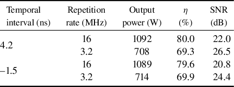
To systematically investigate the influence of temporal intervals on amplification dynamics, the temporal intervals are set to 4.2 and –1.5 ns. As shown in Table 1, at temporal intervals of 4.2 and –1.5 ns, the maximum output powers at a repetition rate of 16 MHz are 1092 and 1089 W, with corresponding η of 80.0% and 79.6%, and spectral SNRs of 22.0 and 20.8 dB, respectively, demonstrating nearly identical amplification performance. Similar amplification characteristics are also observed at a repetition rate of 3.2 MHz.
Amplification characteristics under varying temporal intervals.

Owing to the limited temporal resolution of the current detection system, the minimum temporal interval is controlled at 1.5 ns. Consequently, the above conclusion is strictly valid only for temporal intervals exceeding 1.5 ns. However, as temporal intervals decrease into the ps and sub-ns regime, significant nonlinear inter-pulse interactions are expected to emerge, fundamentally altering the amplification dynamics[ Reference Qi, Wang, Wang, Gao, Zhu, He, Lv, Yang and Lin28]. Specifically, theoretical studies indicate that a diminishing temporal interval between pulses can lead to pronounced competitive energy extraction mediated by gain and loss dynamics[ Reference Chen, Lin, Hu, Wang, Liang, Ling, Yang, Guo, Liu, Chen, Wei and Yang29]. Therefore, elucidating the underlying physical principles of this competitive extraction mechanism warrants further investigation to optimize the performance of USP amplification systems.
3.2.2 Amplification characteristics under low-repetition-rate operation
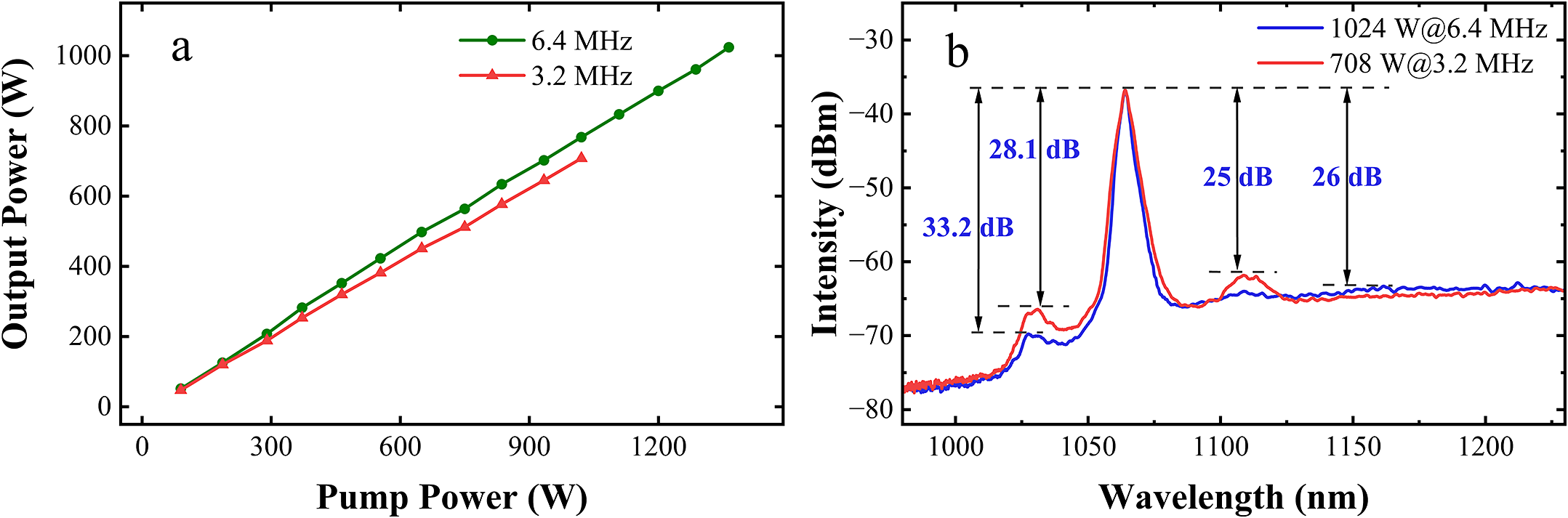
In response to industrial demands for enhanced performance, this study investigates the DPL amplification at 6.4 and 3.2 MHz repetition rates, which support high-energy pulses. Figure 8 presents the output power, spectra and temporal profiles of the DPL. At 6.4 MHz, the system achieves a maximum output power of 1024 W (η = 75.1%) with a spectral SNR of 26 dB, while at 3.2 MHz, the maximum power reaches 708 W (η = 69.3%) with an SNR of 25 dB, as shown in Figures 8(a) and 8(b). The maximum pulse energy of the DPL is 221 μJ (3.2 MHz@708 W). Meanwhile, Figure 8(a) reveals a linear dependence between the DPL output power and pump power under both repetition rate conditions.
(a) The output power of the DPL and (b) the amplified spectra of the DPL at 6.4 and 3.2 MHz.

As demonstrated in Figure 8(b), the measured spectral SNRs exhibit distinct dependencies on repetition rate and output power. At 6.4 MHz with 1024 W output power, the SNR is quantified as 33.2 dB for ASE and 26 dB for SRS. When operating at 3.2 MHz with 708 W output power, the corresponding SNR decreases to 28.1 dB (ASE) and 25 dB (SRS), respectively. This systematic characterization reveals that lower repetition rates significantly promote ASE generation, as evidenced by the SNR reduction[ Reference Zheng, Xie, Liu, He, Qi, Li, He, Liu, Lin and Yang30]. This behavior can be attributed to the reduced energy extraction efficiency under low-repetition-rate operation, which creates favorable conditions for ASE development.
4 Conclusion
This study presents an all-fiber DPL system capable of high-power, temporally adjustable optical pulses. Based on a flexibly tunable DPL generator with independent temporal modulation, DPLs with pulse widths of 5.6 ps and 0.42 ns are successfully achieved, wherein the temporal interval and the power ratio can be continuously adjusted. Meanwhile, the repetition rate can be continuously tuned over a range from 100 kHz to 32 MHz. Furthermore, analysis of various pulse combinations reveals two critical amplification characteristics: (1) the temporal interval (>1.5 ns) exhibits negligible influence on DPL amplification; (2) the amplified power ratio exhibits nonlinear variation due to component-dependent nonlinear effects, and SRS correlates specifically with pulse peak power. The DPL power ratio remains stable during amplification at pulse energies of less than 7.75 μJ (124 W@16 MHz), indicating excellent power-independent control. Using the MOPA configuration, the system achieves a maximum output power of 1092 W at 16 MHz. At 3.2 MHz, the pulse energy of the DPL reaches up to 221 μJ, with the respective pulse widths of 15.9 ps and 0.44 ns. The high-power DPL system represents a paradigm-shifting advancement, combining programmable ps-ns pulse coordination, nonlinear-effect-mitigated kW operation and simultaneous precision-energy delivery, establishing a transformative platform for next-generation scientific and industrial laser applications.
Acknowledgements
This work was financially supported by the National Key R&D Program of China (Grant Nos. 2022YFB3607800 and 2023YFB4604501), the CAS Project for Young Scientists in Basic Research (Grant No. YSBR-065), the National Natural Science Foundation of China (Grant Nos. 62225507, 62175230, 62175232, 62475254 and 62275244) and the Beijing Municipal Science & Technology Commission (Grant No. Z231100006023010).

 Open access