Introduction
Circularly polarized (CP) antennas offer enhanced communication performance compared to linearly polarized antennas, particularly in scenarios involving varying orientations. This advantage helps to mitigate issues such as multipath interference, signal fading, and polarization mismatch. In recent years, there has been significant interest in the study of wideband CP antennas. This growing focus is driven by the increasing demand for faster response times and higher data transmission rates, making wideband and high-gain CP antennas essential in next generation communication systems. CP antennas are widely used in navigation, radar, point-to-point links, and satellite communication systems [Reference Li, Zhang, Qin, Liang, Wei and Li1].
Conventionally, microstrip patch antennas have been used to achieve excellent CP characteristics. These antennas offer several advantages, including reduced physical size, adaptability, conformability, and cost-effectiveness. However, limited impedance bandwidth and axial ratio (AR) bandwidth in resonant antennas present challenges in the effective development and application of CP microstrip antennas. Several techniques have been proposed in the literature to enhance the performance of CP microstrip antennas, including the use of magneto-electric (ME) dipole [Reference Trinh-Van, Yang, Lee and Hwang2], inverted L-shaped patches [Reference Srivastava, Mishra and Singh3], parasitic elements [Reference Wang, Zhu and En4], cross-dipoles [Reference He, He and Wong5], stacked patches [Reference Yang, Zhou, Yu and Li6], dipoles [Reference Wang and Park7], dielectric resonators [Reference Yang, Pan and Yang8], and substrate-integrated waveguides (SIW) [Reference Cai, Zhang, Qian, Cao and Shi9]. In [Reference Trinh-Van, Yang, Lee and Hwang2], the ME dipole antenna is excited using an aperture-coupled feeding structure that incorporates two unequal-length cross slots to achieve overlapping impedance and AR bandwidths ranging from 3.16 to 5.36 GHz (51.35%). In [Reference Srivastava, Mishra and Singh3], an inverted L-shaped patch is used to achieve impedance and AR bandwidths of 50.9% and 16.2%, respectively. In [Reference Wang, Zhu and En4], parasitic elements are used to achieve an impedance bandwidth of 25.8% and an AR bandwidth of 20.6%. In [Reference He, He and Wong5], a cross-dipole antenna is utilized, achieving an AR bandwidth of 27% and a gain of 6.2 dBic. Stacked patches [Reference Yang, Zhou, Yu and Li6] and a hybrid coupler [Reference Wang and Park7] are also used to further enhance bandwidth performance. However, it is noted that these antenna designs lead to non-planar structures, increased profile, and increased complexity.
Recently, researchers have shown great interest in exploring the use of metamaterials for designing highly efficient CP antennas [Reference Hussain, Jeong, Abbas, Kim and Kim10 –Reference Zhang, Zhang and Wu17]. Metamaterials are artificially engineered three-dimensional (3D) structures that can exhibit properties such as negative refraction, primarily due to their sub-wavelength structural features. A metasurface is the two-dimensional (2D) counterpart of a metamaterial and consists of a thin layer of meta-atoms, enabling efficient wavefront manipulation at the surface level. Compared to other techniques, metasurface-based antennas offer distinct advantages, such as wide operational bandwidth, less complexity, low cost, compact size, and high radiation efficiency.
A square patch with corner truncation and rectangular diagonal slots is used to generate CP in [Reference Hussain, Jeong, Abbas, Kim and Kim10]. A 4 $\times$4 symmetrical square-ring metasurface is placed above the source antenna, achieving a $-$10 dB impedance bandwidth of 34.7% and a 3-dB AR bandwidth of 20.1%. Bowtie-shaped slots along with a periodic 4 $\times$4 array of corner-truncated patches are utilized in [Reference Nkimbeng, Wang and Park11] to enhance CP performance. A microstrip patch antenna integrated with a metasurface achieved a global bandwidth of 12.4% and a gain of 7 dBic [Reference Tran and Park13]. A compact planar slot-coupling antenna designed for C-band applications incorporates a metasurface to improve performance, achieving an impedance bandwidth of 33.7% and an AR bandwidth of 18.5% [Reference Wu, Li, Li and Chen14]. A single-fed corner truncated wideband CP antenna is presented in [Reference Ta and Park15]. The antenna dimensions are relatively compact, measuring 0.58 $\times$0.58 $\times$0.056 $\lambda_{o}^3$. It exhibits impedance and AR bandwidths of 45.6% and 23.4%, respectively. Although the integration of metasurfaces represents a promising approach to significantly enhancing the AR bandwidth of conventional antennas, its limited capability to manipulate electromagnetic waves restricts its widespread adoption in antenna design. Consequently, non-uniform metasurface is gaining popularity in antenna design due to their adoptable structure and efficient control over electromagnetic wave propagation.
Non-uniform metasurface are used in MIMO antennas [Reference Sehrai, Asif, Shah, Khan, Ullah, Ibrar, Jan, Alibakhshikenari, Falcone and Limiti18], filtering antennas [Reference Park, Jeong, Hussain, Rhee, Park and Kim19], bandwidth enhancement [Reference Banting and Saavedra20], beam generation [Reference Ran, Cai, Shi, Wang, Liang, Wu, Li and Liu21], and reconfigurable antennas [Reference Li, Wu, Huang, Wu, Ma, Liang and Huang22]. The non-uniform metasurface-based CP antennas reported in the literature use slots [Reference Han, Zheng, Su, Yuan and Zhang23], L-slots [Reference Iqbal, Khan and Ahmed24], coupling slots [Reference Chen, Chin, Yang, Jin, Cao, Chen and Cao25], cross-slots [Reference Cui, Zhao and Sheng26], and corner truncation [Reference Tran, Bui, Nguyen-Trong and Nguyen29] to achieve wideband CP characteristics. In [Reference Iqbal, Khan and Ahmed24], the utilization of a uniform metasurface resulted in an operating bandwidth of 26.7%, while the use of a non-uniform metasurface increased it substantially to 71.7%. A high-gain wideband antenna based on non-uniform metasurface with 26.73% fractional bandwidth and 8.54 dBi peak gain is proposed for wearable antenna applications [Reference Gao, Meng, Geng, Zhang, Dou and Hu27].
A metasurface is composed of a periodic array of sub-wavelength unit cells. In CP antennas, the metasurface typically functions as a superstrate that interacts with the radiating patch and modifies the overall antenna characteristics. For effective CP radiation, two orthogonal modes must be excited with equal amplitude and a 90 $^\circ$ phase difference. In [Reference Banting and Saavedra20], it is concluded that the non-uniform metasurface geometries significantly improve bandwidth compared to uniform geometries. Uniform designs derive their bandwidth from multiple radiating modes determined by unit cell size and periodicity; however, this structure offers limited degrees of freedom, restricting the tunable range and individual control of the excited modes. Conversely, the non-uniform metasurface provides additional degrees of freedom, which improves the tunable range and allows for the excitation of several higher-order modes, features often unachievable with uniform designs. This ability to support additional resonant modes leads to enhanced bandwidth and better impedance matching, with a 4 $\times$4 non-uniform structure achieving 51.8% fractional bandwidth. Similarly, the antenna design presented in [Reference Le, Kim and Yun28] shows that varying unit cell sizes excites resonant modes at different frequencies, resulting in a wider operational bandwidth. While the uniform configuration realizes only a narrow CP band from its central unit cells, introducing non-uniformity excites additional resonant modes at the outer unit cells, creating multiple overlapping CP bands [Reference Tran, Bui, Nguyen-Trong and Nguyen29]. This mechanism leads to significantly broader impedance and AR bandwidths, extending the overall 3-dB AR bandwidth to about 30%.
In this paper, a low-profile wideband CP antenna based on uniform and non-uniform metasurfaces for C-band applications is presented. The novelty of the proposed antenna lies in the strategic use of non-uniform metasurfaces to design and develop a wideband CP antenna. The radiating element consists of a stub-inserted dual-feed square patch, fed by a sequential feed network. The primary objective is to evaluate the performance of a microstrip patch antenna by initially using a uniform metasurface as the superstrate and then optimizing it with a non-uniform metasurface to achieve a wider bandwidth and additional CP resonances. The proposed non-uniform metasurface demonstrates the ability to generate supplementary resonances, which combine with the patch resonance to achieve a broad operating bandwidth. The rest of this paper is organized as follows: Section II presents the detailed antenna design, covering the dual-feed antenna, the feeding network, and the unit cell design. Section III then discusses the antenna’s working principle. Section IV provides the detailed simulated and measured results of the proposed antenna. Section V presents a performance comparison of the proposed antenna with other relevant works reported in the literature. Finally, Section VI provides the concluding remarks.
Antenna design
Figures 1 and 2 present geometrical design of the proposed antenna, comprising of three main parts: a dual-feed microstrip patch as the driven element, a metasurface as the superstrate, and a feed network. The feed network is placed on the bottom layer, the microstrip patch is in the middle, and the metasurface is on the top layer. The antenna is designed and fabricated using an FR4 glass epoxy substrate with a dielectric constant ( $\epsilon_r$) of 4.4, thickness (h) of 0.8 mm, and loss tangent ( $\tan\delta$) of 0.02. The metasurface layer and the patch layer are separated by an air gap ( $h_{1}$) of 1 mm. The proposed antenna design is simulated using Ansys High Frequency Structure Simulator (HFSS) software [30].

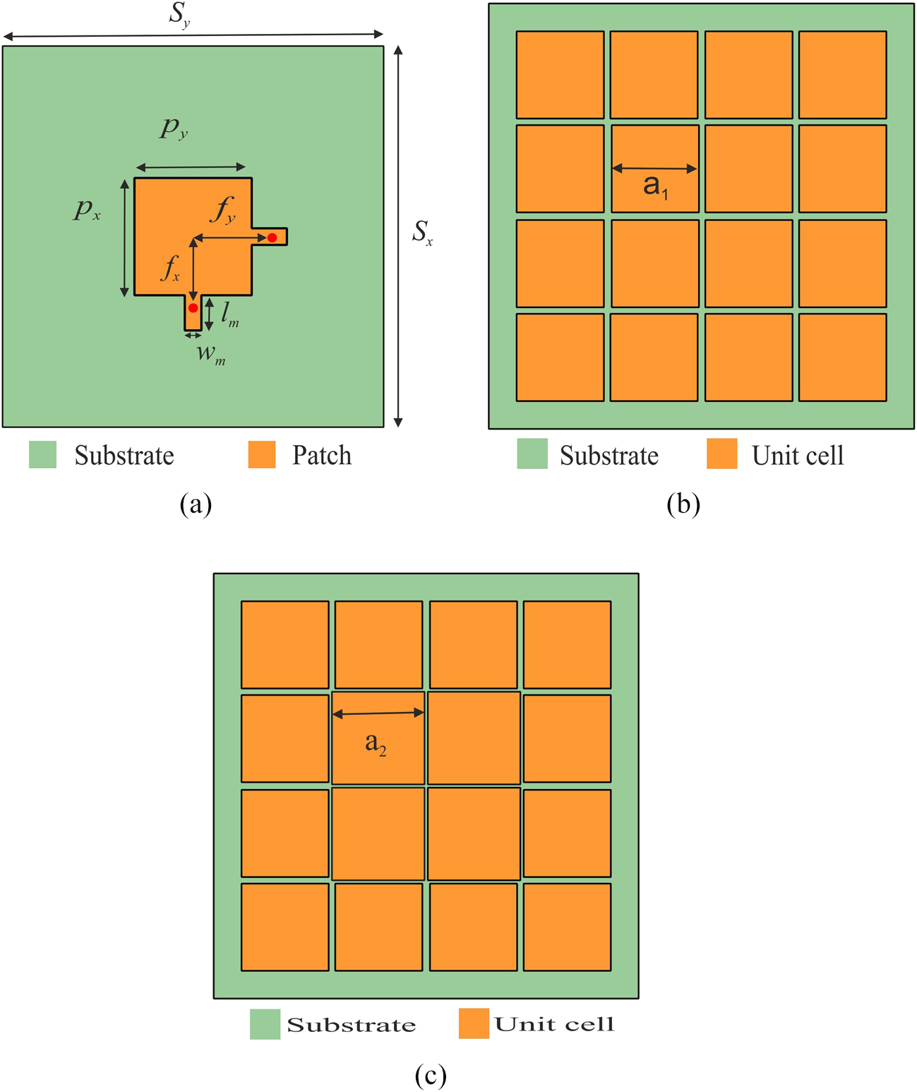
Figure 1. Proposed dual-feed non-uniform metasurface antenna configuration. (a) Cross-sectional view. (b) Layered structure view.

Figure 2. Top view of (a) Dual-feed patch antenna, (b) Uniform metasurface, and (c) Non-uniform metasurface.
Dual-feed patch antenna
The length and width of the dual-feed square-shaped patch are optimized to operate in the fundamental TM $_{11}$ and are calculated using the formula provided in Equation 1. Here, $c$ represents the speed of light, $\epsilon_{eff}$ is the effective permittivity of the substrate, $W$ is the width of the patch, and $f_{r}$ is the resonating frequency of the antenna. To improve impedance matching, two rectangular stubs with dimensions $l_{m}\times w_{m}$ are attached to the patch along the $x$-axis and $y$-axis, respectively. These stubs are connected via two SMA connectors with an impedance of 50 $\Omega$ to excite the patch, and the connectors are fed by the feed network. The feed points are positioned at distances $f_{x}$ along the $x$-axis and $f_{y}$ along the $y$-axis from the center of the patch. Optimized dimensions of the dual-feed patch antenna are as follows: $p_{x} = 12\,\mathrm{mm}$, $p_{y} = 12\,\mathrm{mm}$, $f_{x} = 8\,\mathrm{mm}$, $f_{y} = 8\,\mathrm{mm}$, $l_{m} = 3\,\mathrm{mm}$, and
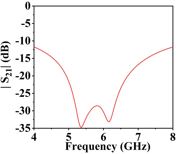
  $w_{m} = 1.5\,\mathrm{mm}$. Figure 3 shows the mutual coupling $|S_{21}|$ between the two orthogonal feeds. From the results, it can be seen that the isolation remains below $-$15 dB across the 4 to 8 GHz band, with a minimum value of about $-$34 dB around 5.4 GHz.
 \begin{equation}
W=\frac{c}{2{{f}_{r}}\sqrt{{{\in }_{eff}}}}
\end{equation}
\begin{equation}
W=\frac{c}{2{{f}_{r}}\sqrt{{{\in }_{eff}}}}
\end{equation}
Figure 3. Simulated port to port isolation ( $S_{21}$) of the dual-feed antenna.
Feeding network
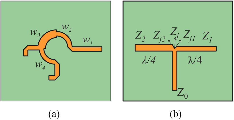
The stub-inserted dual-feed square patch antenna is energized through a sequential rotational feed network located on the bottom layer. This network ensures uniform amplitude and progressive phase shifts, enhancing CP performance. It uses a T-junction power divider design, as shown in Figure 4, and includes quarter-wavelength transmission line sections to ensure proper impedance matching and efficient signal distribution. A T-junction power divider is selected because it offers a simple structure, low insertion loss, and compact size, which are suitable for wideband operation and easier integration with the proposed antenna. Other dividers such as branch-line couplers or Wilkinson dividers generally provide excellent isolation and matching but complex to design. The characteristic impedances  $Z_{0}$, $Z_{1}$, and $Z_{2}$ are set to 50 $\Omega$ to ensure balanced power division and minimize signal reflection. At the T junction, a junction capacitance is introduced, represented as $Z_j$, which significantly influences the impedance behavior of the feed network. The accurate calculation of $Z_j$ is crucial for minimizing signal degradation and is determined using the Equation 2. From Equation 2, $Z_j$ is calculated to be 25 $\Omega$. Using this value, the required characteristic impedance of the line segments can be determined from Equation 3, resulting in $Z=35.35\;\Omega$. This calculation is extended to determine the impedance of the remaining line segments within the feed network.
 \begin{equation}
Z_j = \frac{z_1 z_2}{z_1 + z_2}
\end{equation}
\begin{equation}
Z_j = \frac{z_1 z_2}{z_1 + z_2}
\end{equation} \begin{equation}
Z = \sqrt{Z_j Z_0}
\end{equation}
\begin{equation}
Z = \sqrt{Z_j Z_0}
\end{equation}
Figure 4. (a) T-junction power divider-based feed network design with optimized dimensions:  $\textit{w}_{1} = 1.5\,\mathrm{mm}$, $\textit{w}_{2} = 2.6\,\mathrm{mm}$, $\textit{w}_{3} = 1.5\,\mathrm{mm}$, and $\textit{w}_{4} = 1.5$ and (b) Representations of the line and junction impedance at the T-junction.
The corresponding feed line widths are derived on the basis of the calculated impedance values. Once the characteristic impedance is determined, the widths of the microstrip sections are calculated accordingly and shown in Figure 4(a). This feed topology is carefully designed with optimized lengths and widths to ensure efficient power distribution. The input network provides a 90 $^\circ$ phase shift, enabling equal power distribution between adjacent output ports. This phase shift is achieved by varying the lengths of the transmission paths from the input to each output port, with each path differing by a quarter wavelength. Figure 5(a) shows the S-parameters of the proposed feed network, where good impedance matching and power division characteristics are observed. Figure 5(b) presents the phase response, confirming that the network maintains a stable phase difference between the output ports across the operating band, thereby ensuring proper quadrature excitation and validating the phase balance accuracy.

Figure 5. Characteristics of the feed network. (a) Magnitude. (b) Phase.
Unit cell
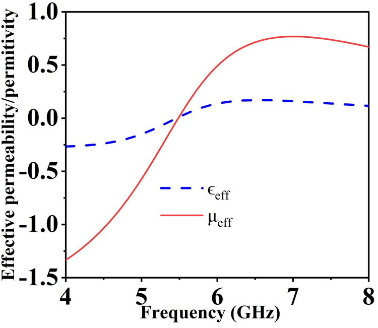
Performance of the proposed antenna is enhanced through the integration of a reflective metasurface composed of unit cells engineered to exhibit a zero-phase reflection response. This metasurface is an artificially engineered structure formed by an array of electrically compact resonators, commonly referred to as unit cells. Parameter extraction analysis of effective permittivity ( $\epsilon_{eff}$) and permeability ( $\mu_{eff}$) is shown in Figure 6. The retrieved results show that $\epsilon_{eff}$ is negative in the 4 to 5.5 GHz band before becoming positive, while $\mu_{eff}$ remains slightly negative in the same band and shifts toward near-zero or positive values beyond 6 GHz. This double-negative (DNG) region, followed by single-negative and near-zero responses, is a typical feature of engineered metasurface, thereby confirming the proposed design as a metasurface.

Figure 6. Extracted effective permittivity ( $\epsilon_{eff}$) and permeability ( $\mu_{eff}$) of the proposed unit cell.
Each unit cell is specifically designed to demonstrate electromagnetic properties that collectively determine overall functionality of the metasurface [Reference Sievenpiper, Zhang, Broas, Alexopoulos and Yablonovitch31]. The size of each individual unit cell is maintained within the range  $\frac{{{\lambda }_{0}}}{20}\le s\le \frac{{{\lambda }_{0}}}{4}$, where $s$ is the dimension of the unit cell and
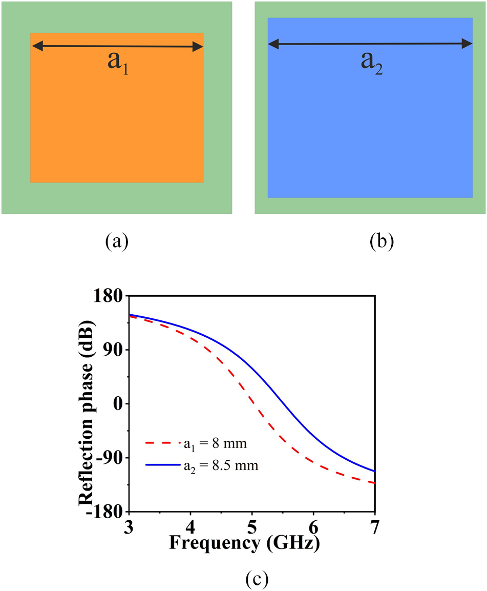
  $\lambda_{0}$ represents free space wavelength. The proposed square-shaped unit cell is designed in two variations: unit cell-1, with a side length of $a_1 = 8\,\mathrm{mm}$, as shown in Figure 7(a), and unit cell-2, with a side length of $a_2 = 8.5\,\mathrm{mm}$, as shown in Figure 7(b). Dimensions of the unit cell are selected after a detailed parametric analysis. Unit cell dimensions of 8 mm and 8.5 mm are selected to excite the surface waves and to achieve effective coupling between the source antenna and metasurface. This helps to achieve wide CP operating bandwidth with enhanced gain.

Figure 7. (a) Geometrical design of unit cell-1. (b) Geometrical design of unit cell-2. (c) Reflection phase characteristics of unit cell-1 and unit cell-2.
The reflection phase responses of the proposed unit cells, illustrated in Figure 7(c), vary from  $-$90
$-$90 $^\circ$ to $+$90
$+$90 $^\circ$. This indicates support for in-phase reflection behavior associated with high surface impedance. Performance of unit cells is evaluated within the frequency ranges of 4.45 to 5.9 GHz for unit cell-1 and 4.7 to 6.5 GHz for unit cell-2, using Floquet port boundary conditions in HFSS. In this paper, two metasurfaces are designed for performance evaluation: a uniform metasurface and a non-uniform metasurface. Each metasurface is composed of a 4 $\times$4 array of unit cells. The uniform metasurface consists entirely of unit cell-1 elements, arranged with an inter-element gap of $g_1 = 0.5\,\mathrm{mm}$. In contrast, the non-uniform metasurface is formed by a combination of unit cell-1 and unit cell-2 elements within the array.
Working principle
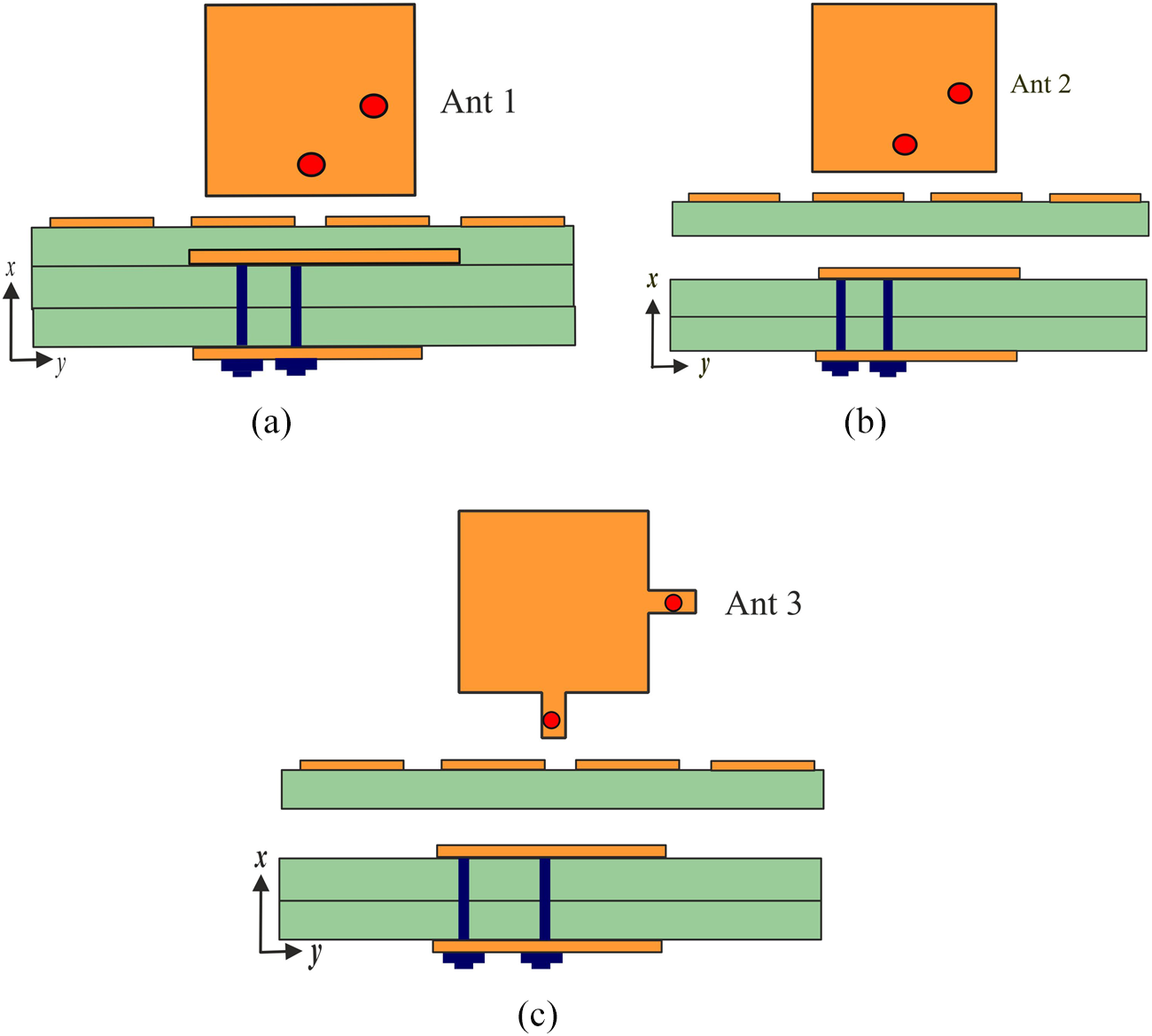
The proposed antenna design utilizes both uniform and non-uniform metasurfaces to achieve broadband CP through an orthogonally fed dual-feed mechanism on the patch. Evolution of the antenna design, along with the step-by-step design methodology, is illustrated in Figure 8. The simulated results of the antenna with and without metasurface is shown in Figure 9. The metasurface improves the  $-$10 dB impedance bandwidth from 3.4% to 21.57%. The 3-dB ARBW with the metasurface is found to be 50.9%. The peak gain of the antenna is 5.7 dBic without the metasurface and 8.7 dBic with it, respectively. From these results, it can be concluded that the metasurface significantly enhances the operating characteristics of the proposed antenna.

Figure 8. Design evolution of the proposed antenna structure. (a) Initial patch with metasurface. (b) Patch with metasurface and air gap. (c) Final optimized design (patch with stubs, metasurface, and air gap).

Figure 9. Simulated (a)  $|S_{11}|$, (b) AR, and (c) Broadside gain of the proposed antenna with and without metasurface.
Antenna 1 (Ant 1) features a dual-feed patch and a uniform metasurface. The metasurface, printed on the top layer, consists of a 4 $\times$4 array of unit cell-1 elements, with a length of $S_x = 40\,\mathrm{mm}$ and width $S_y = 40\,\mathrm{mm}$. The Ant 1 exhibits a narrow impedance bandwidth of 4.58 to 4.8 GHz (8.1%), 3-dB AR bandwidth of 3.23 to 7.25 GHz (76%), and a peak gain of 6.4 dBic. Dual-feed antennas are generally characterized by a narrow impedance bandwidth and a wide AR bandwidth. To improve the overall operating bandwidth, an air gap is introduced between the metasurface and the patch layer. To analyze the effect of air gap height ( $h_{1}$), the proposed antenna design is simulated with different values of $h_{1}$. Figure 10 shows the reflection characteristics for different values of $h_{1} = 0.5\,\mathrm{mm}$, 1 mm, 2 mm, 3 mm and 4 mm. From these results it can be seen that $h_{1} = 1\,\mathrm{mm}$ provides widest operational bandwidth as compared with the other values. This 1 mm gap effectively enhances the operating bandwidth while simultaneously maintaining a low profile for the antenna, representing the optimal trade-off between bandwidth enhancement and antenna profile.

Figure 10. Effect of varying the air gap ( $h_{1}$) between the patch and metasurface at 0.5, 1, 2, 3, and 4 mm.
An air gap of  $h_{1} = 1\,\mathrm{mm}$ is introduced between the metasurface and the patch layer, resulting in antenna 2 (Ant 2). This configuration achieves an impedance bandwidth of 5.1 to 5.46 GHz (6.8%), a gain of 8.5 dBic, and an AR bandwidth spanning from 4.5 to 6.9 GHz (42%). It is noted that both Ant 1 and Ant 2 configurations exhibit narrow impedance bandwidth but comparatively wider AR bandwidth. To enhance the overall bandwidth, extended stubs with dimensions $l_{m} \times w_{m}$ are added to the source antenna, resulting in Antenna 3 (Ant 3) with a uniform metasurface. The addition of stubs in Ant 3 achieves an improved impedance bandwidth of 5.21 to 6.47 GHz (21.57%), an AR bandwidth of 3.96 to 6.67 GHz (50.9%), and a gain of 8.4 dBic. Figure 11 shows the simulated results for different antenna configurations. Based on the simulated results, it can be concluded that Ant 3 demonstrates superior impedance and AR bandwidth performance compared to Ant 1 and Ant 2.

Figure 11. Simulated results for different antenna configurations. (a)  $|S_{11}|$, (b) AR, and (c) Gain.
To further improve the performance of the proposed antenna, a non-uniform metasurface configuration is employed. This metasurface is developed and optimized to enhance the overall antenna performance while maintaining the same radiating element and feed network. It consists of an array that combines both unit cell-1 and unit cell-2. Specifically, the outer layer of unit cells is composed of unit cell-1, while the inner region incorporates unit cell-2. Antenna 4 (Ant 4) is derived by modifying the inner four unit cells of Ant 3, while keeping the dimensions of the outer unit cells unchanged.
A parametric analysis is conducted by varying the dimension  $a_2$ of unit cell-2 within the non-uniform metasurface. Figure 12 presents the simulated reflection coefficient, AR, and gain performance for the proposed antenna across different $a_2$ values. As shown in Figure 12(a), the antenna maintains a broad impedance bandwidth across all $a_2$ values. Figure 12(b) demonstrates that the AR remains below 3 dB over a wide bandwidth for every configuration, with the $a_2 = 8.5\,\mathrm{mm}$ case providing the most stable AR response and minimal fluctuations. Furthermore, the gain performance depicted in Figure 12(c) shows a gradual increase in gain as $a_2$ increases. This analysis confirms that the antenna’s performance is significantly influenced by $a_2$, and the optimized value of $a_2 = 8.5\,\mathrm{mm}$ delivers superior performance regarding AR stability and gain while retaining excellent impedance matching.

Figure 12. Parametric analysis of non-uniform metasurface antenna with varying  $a_{2}$ dimensions. (a) $|S_{11}|$, (b) AR, and (c) Gain.
The use of a non-uniform 4 $\times$4 metasurface thus results in substantial improvements in both impedance and AR bandwidths. The simulated performance comparisons between Ant 3 and Ant 4 are illustrated in Figure 13. Specifically, while Ant 3 exhibits an impedance bandwidth of 5.21 to 6.47 GHz (21.57%), Ant 4 achieves a significantly wider impedance bandwidth of 4.92 to 7.35 GHz (40%). Furthermore, Ant 4 shows enhanced AR performance, supporting dual CP bands from 2.1 to 7.26 GHz (113%) and 7.78 to 8.57 GHz (9.6%), whereas Ant 3 achieves an AR bandwidth of 3.96 to 6.67 GHz (50.9%). Figure 14 illustrates the normalized radiation pattern in $xz$-plane and $yz$-plane. It is observed that the antenna exhibits broadside radiation even at higher frequencies. Additionally, the surface current distributions of the proposed non-uniform metasurface with a dual-feed patch, for phase angles ranging from 0 $^\circ$ to 360 $^\circ$ in 90 $^\circ$ steps, are shown in Figure 15. The observed current flow pattern moves from right to left, indicating right-hand circular polarization (RHCP).

Figure 13. Comparative simulated results of antenna with uniform metasurface and non-uniform metasurface. (a)  $|S_{11}|$, (b) AR, and (c) Gain.

Figure 14. Normalized simulated radiation patterns of the proposed antenna at different frequencies. (a)  $xz$-plane at 5 GHz, (b) $yz$-plane at 5 GHz, (c) $xz$-plane at 5.5 GHz, (d) $yz$-plane at 5.5 GHz, (e) $xz$-plane at 6 GHz, (f) $yz$-plane at 6 GHz, (g) $xz$-plane at 7 GHz, (h) $yz$-plane at 7 GHz, (i) $xz$-plane at 7.5 GHz, and (j) $yz$-plane at 7.5 GHz.

Figure 15. Surface current distributions of non-uniform metasurface antenna at different phase angles. (a) 0 $^\circ$, (b) 90 $^\circ$, (c) 180 $^\circ$, and (d) 270 $^\circ$.
Results and discussion
This section presents detailed simulated and measured results of the proposed antenna, which consists of a dual-feed patch antenna with a non-uniform metasurface as a superstrate. The 4 $\times$4 non-uniform metasurface based CP dual-feed patch antenna is fabricated and tested. The patch, feed network, and non-uniform metasurface are printed on an FR4 substrate. Figure 16 presents photos of the fabricated antenna and the testing setup used in the anechoic chamber. The overall size of the proposed antenna is 40 mm $\times$ 40 mm $\times$ 3.4 mm (0.72 $\lambda_{0}$ $\times$ 0.72 $\lambda_{0}$ $\times$ 0.062 $\lambda_{0}$). The reflection coefficient of the prototype is measured using an Agilent N5230A network analyzer and a 3.5 mm coaxial calibration standard GCS35M. For the radiation pattern measurements, an Agilent E8362B network analyzer and an anechoic chamber with dimensions of 15.2 m (W) $\times$ 7.9 m (L) $\times$ 7.9 m (H) are used. Figure 16(d) specifically shows the arrangement of the feeding probes connected from the feed network to the source antenna. The two coaxial feed connectors on the antenna and the two on the feed network are used to supply the signal. To minimize losses and improve the accuracy of our results, two low-loss RF cables (Model No. 7029-2555, TE Connectivity, RF Cable Assemblies SMA M to SMA M C/A 047 Cable (OAL 6”)) are connected between the feeding ports and the dual-feed source antenna. Some discrepancies are observed between the simulated and measured results, which can be attributed to factors such as fabrication tolerances, the effects of the RF connectors, and cable losses.

Figure 16. Photographs of the proposed antenna. (a) Feed layer, (b) Patch layer, (c) Non-uniform metasurface layer, (d) 3D-printed holding assembly, and (e) Testing setup.
The simulated impedance bandwidth extends from 4.92 to 7.35 GHz (40%), while the measured impedance bandwidth ranges from 4.98 to 7.45 GHz (40%), as illustrated in Figure 17(a). The simulated AR bandwidth ranges from 2 to 7.26 GHz (113%). The measured AR bandwidth spans from 2.8 to 7.8 GHz (94.34%), as shown in Figure 17(b). The simulated and measured gains are 8.7 dBic and 8.5 dBic, respectively, as presented in Figure 17(c). In the high-frequency range, the broadside gain became much lower. A similar effect is seen in the antenna discussed in [Reference Ta and Park15]. Comparison of simulated and measured results of the proposed antenna is summarized in Table 1.

Figure 17. Simulated and measurement results of the proposed non-uniform metasurface antenna. (a)  $|S_{11}|$, (b) AR, and (c) Gain.
Table 1. Comparison of simulated and measured results of the proposed antenna

Figure 18 presents the normalized radiation patterns of the antenna at three different frequencies: 5 GHz, 5.5 GHz, and 6 GHz, in both the  $\textit{xz}$-plane and $\textit{yz}$-plane. At all frequencies, the antenna exhibits a dominant RHCP component in the broadside direction, confirming its strong circular polarization capability. The LHCP component remains minimal, demonstrating excellent polarization purity. The antenna maintains stable broadside radiation across the operating frequencies, with peak gains ranging from 8.4 to 8.7 dBic. The front-to-back ratio is 25 dB at 5 GHz, 26 dB at 5.5 GHz, and 24 dB at 6 GHz. The variation between measured and simulated gain values is minimal, within
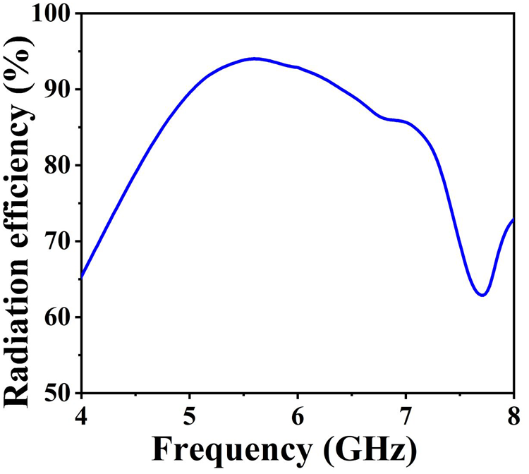
  $\pm$0.3 dB, indicating strong correlation and validating the design accuracy. Furthermore, the measurements confirm stable radiation performance across the entire operating frequency range, making the design highly suitable for wideband applications. The antenna also demonstrates high efficiency, with efficiency exceeding 90%. Figure 19 shows the simulated radiation efficiency of the proposed antenna. It can be observed that the efficiency remains above 90% over most of the operating band, reaching a peak value of about 92% around 5.6 GHz. The efficiency stays higher than 85% up to approximately 6.8 GHz, which fully covers the CP bandwidth of the antenna. A dip is observed around 7.4 to 7.7 GHz, where the efficiency decreases to about 62%, this is due to higher-order resonances and surface wave excitation that increase reactive losses. Nevertheless, within the CP band, the radiation efficiency remains consistently above 90%, ensuring that the antenna maintains high performance in its intended operating range.

Figure 18. Normalized simulated and measured radiation patterns of the proposed antenna at different frequencies. (a)  $xz$-plane at 5 GHz, (b) $yz$-plane at 5 GHz, (c) $xz$-plane at 5.5 GHz, (d) $yz$-plane at 5.5 GHz, (e) $xz$-plane at 6 GHz, and (f) $yz$-plane at 6 GHz.

Figure 19. Simulated radiation efficiency of the proposed antenna.
Performance comparison
The comparison Table 2 presents the performance metrics of various antenna designs, including the proposed antenna, focusing on overall size, impedance bandwidth, 3-dB AR bandwidth, and peak gain. The antenna designs presented in [Reference Nkimbeng, Wang and Park11], [Reference Srivastava, Mishra and Singh3], [Reference He, He and Wong5], [Reference Wu, Li, Li and Chen14], [Reference Ta and Park15], and [Reference Iqbal, Khan and Ahmed24] offer good impedance bandwidth and relatively small antenna sizes. However, their AR bandwidth is comparatively lower. Conversely, the high-gain antennas in [Reference Hussain, Jeong, Abbas, Kim and Kim10], [Reference Wang, Zhu and En4], [Reference Yang, Zhou, Yu and Li6], and [Reference Zhang, Zhang and Wu17] demonstrate limited impedance bandwidth and AR bandwidth. The proposed antenna design is optimized to achieve wide operating bandwidth with stable radiation patterns and high gain. It is concluded that employing a metasurface as a superstrate helps enhance the overall bandwidth and gain of conventional narrowband CP antennas that typically exhibit low gain. Antenna designs reported in [Reference Hussain, Jeong, Abbas, Kim and Kim10] and [Reference Zhang, Zhang and Wu17] achieve a higher gain than the proposed antenna; however, the design in [Reference Hussain, Jeong, Abbas, Kim and Kim10] uses a Rogers 5880 substrate (loss tangent of 0.0009) and the design in [Reference Zhang, Zhang and Wu17] uses a Rogers 4003 substrate (loss tangent of 0.0027). In contrast, the proposed antenna design is designed and developed using a low-cost FR4 substrate, which has a significantly higher loss tangent of 0.02. This high loss tangent directly affects the gain of the proposed antenna design, which could be further increased by forming a 2 $\times$2 or 4 $\times$4 array structure.
Table 2. Performance comparison of the proposed wideband CP antenna with earlier reported works

Conclusion
In this paper, a wideband CP antenna demonstrates exceptional performance for C-band applications. The antenna comprises a dual-feed patch as a source antenna with 4 $\times$4 non-uniform metasurface as a superstrate. The proposed antenna achieves a wide impedance bandwidth of 4.98 to 7.45 GHz (40%). The antenna provides a broad AR bandwidth of 2 to 7.26 GHz (113%) in the lower frequency band and 7.78 to 8.57 GHz (9.6%) in the higher frequency band. These characteristics, along with its stable broadside radiation pattern, make the proposed antenna highly suitable for modern communication systems such as wireless local area networks, satellite communication, cordless telephones, and C-band applications. In future work, the operation of the proposed antenna will be analyzed to verify its performance in the presence of radome effects, mutual coupling in array configurations, and system integration response for real-world C-band satellite communication applications.
Competing interests
The author(s) declare none.

Sandireddy Ramadevi received the B.Tech. degree in electronics and communication engineering from Vardhaman College of Engineering, Hyderabad, Telangana, India, in 2008, and the M.Tech. degree in Embedded Systems from Chilkur Balaji Institute of Technology, Hyderabad, Telangana, India, in 2014. She is currently internal full time research scholar with the School of Electronics Engineering (SENSE), VIT-AP University, Amaravati. Her research interests include wideband circularly polarized antennas using metamaterials for C-band and satellite applications.

Vikas Vishnu Khairnar (Member, IEEE) received the B.E. degree in electronics and telecommunication engineering from Savitribai Phule Pune University, India, in 2009, the M.E. degree in communication engineering from Dr. BAMU University, India, in 2013, and the Ph.D. degree from BITS Pilani, India, in 2020. He is currently working as an Associate Professor with the School of Electronics Engineering (SENSE), VIT-AP University, Amaravati, Andhra Pradesh, India. His research interests include the design of reconfigurable antennas, antenna arrays, and metasurface-inspired antennas.