

1 Introduction
In inertial confinement fusion (ICF) research, the Lebedev Physical Institute (LPI) is now focusing on the noncontact positioning and transport of free-standing cryogenic targets at the powerful laser facility. A feature of the current developments is that the technologies being created must take into account many stringent requirements on the successful delivery process related to a future laser-driven ICF reactor. The top-level requirements[ Reference Goodin, Alexander, Brown, Frey, Gallix, Gibson, Maxwell, Nobile, Olson, Petzoldt, Raffray, Rochau, Schroen, Tillack, Rickman and Vermillion 1 ] are given in Table 1.
Target acceleration requirements for ICF.
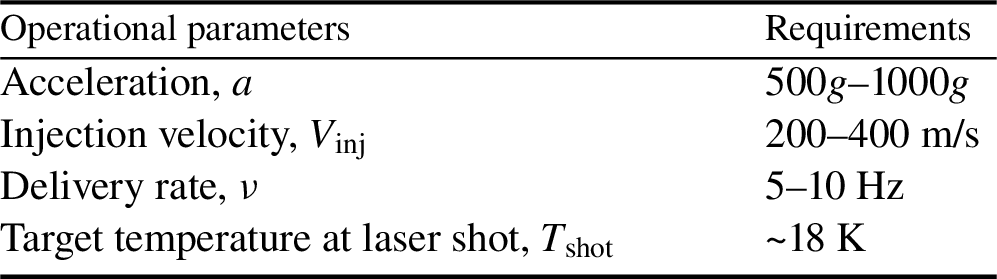
Note: g is the free-fall acceleration.
To meet these challenging requirements, a number of laser facilities for high-power laser experiments with shot repetition rates between 1 and 10 Hz are being developed[ Reference Prencipe, Fuchs, Pascarelli, Schumacher, Stephens, Alexander, Briggs, Büscher, Cernaianu, Choukourov, De Marco, Erbe, Fassbender, Fiquet, Fitzsimmons, Gheorghiu, Hund, Huang, Harmand, Hartley, Irman, Kluge, Konopkova, Kraft, Kraus, Leca, Margarone, Metzkes, Nagai, Nazarov, Lutoslawski, Papp, Passoni, Pelka, Perin, Schulz, Smid, Spindloe, Steinke, Torchio, Vass, Wiste, Zaffino, Zeil, Tschentscher, Schramm and Cowan 2 ]. In addition, issues related to target injection and laser engagement are under active consideration. In Ref. [Reference Mori, Ishii, Hanayama, Okihara, Kitagawa, Nishimura, Komeda, Hioki, Motohiro, Sunahara, Sentoku, Iwamoto, Sakagami, Miura and Johzaki3], the authors demonstrated 10 Hz free-fall bead pellet injection and laser engagement with γ-ray generation. The studies discussed in Ref. [Reference Mori, Ishii, Hanayama, Okihara, Kitagawa, Nishimura, Komeda, Hioki, Motohiro, Sunahara, Sentoku, Iwamoto, Sakagami, Miura and Johzaki3] were conducted at room temperature (300 K). However, any target injector must operate at a very low temperature, allowing no heat energy transfer into the target from the accelerating medium, that is, no target heating above T ~ 18 K.
Therefore, new solutions for target delivery systems are essential for modern ICF experiments. In this paper we consider different superconducting magnetic levitation (maglev) systems that can accelerate the targets up to required values of V inj, and can overcome mechanical friction.
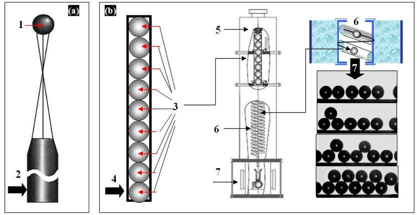
The simplest direct-drive cryogenic target is a spherical deuterium-tritium (DT) fuel ice layer enclosed by a thin polymer shell. The generally accepted approach is that each target during delivery is inserted into a target sabot to protect them from thermal and mechanical overloads (Figure 1). Table 1 shows the accelerations imposed on the target, which are likely to be required for an ICF reactor. However, it is desirable to work at lower accelerations since the target must reliably survive the injection overloads without damage. In Section 3 we will define the conditions to achieve the required injection velocity without exceeding acceleration limitations.
Assembly of the HTSC-sabot + target, or HTSC-projectile (not to scale): (a) 1 – HTSC-housing, 2 – polymer insert with a target nest on its top, 3 – MgB2 driving coils, 4 – cryogenic target; (b) 5 – mock-up of the HTSC-housing made from superconducting ceramics, ρ = 4 g/cm3 [ Reference Miles, Spaeth, Manes, Amendt, Tabak, Bond, Kucheyev, Latkowski, Loosmore, Bliss, Baker, Bhandarkar, Petzoldt, Alexander, Tillack and Holdener 4 , Reference Aleksandrova, Koresheva and Koshelev 5 ], 6 – hole for the polymer insert; (c) 7 – target shell, 8 – solid fuel layer, 9 – vapor fuel.

Temperature limitations are as follows: (1) target heating up to the triple point (19.79 K) must be excluded so that the DT remains uniformly frozen within the capsule surface (Figure 1(c)); (2) for obtaining the maximum energy yield from target implosions, the DT fuel must be at approximately 18 K when the target reaches the laser focus (see Table 1); and, finally, (3) the maximum allowable DT temperature change during target delivery is approximately 100 mK[ Reference Miles, Spaeth, Manes, Amendt, Tabak, Bond, Kucheyev, Latkowski, Loosmore, Bliss, Baker, Bhandarkar, Petzoldt, Alexander, Tillack and Holdener 4 ].
Thus, the ability of the DT target to withstand overloads and overheating is a key in the target accelerator design. The scientific and technological issues associated with this task are as follows: (1) design bases must provide a noncontact target acceleration (i.e., without mechanical friction) to avoid heating the DT ice layer; (2) as a consequence, it removes the issue of developing cryogenic lubricants, the effectiveness of which at cryogenic temperatures (<20 K) is highly questionable; (3) it is desirable for accelerations imposed on the target to be within acceleration limitations; (4) design solutions must be rather compact to significantly reduce the target production costs; (5) design solutions must also be compatible with mass target fabrication and operation at high repetition rate (HRR) conditions[ Reference Aleksandrova, Koresheva and Koshelev 5 ].
The last condition (5) is very important for the implementation of in-line target production, which requires one to develop fabrication technologies working with free-standing (un-mounted) targets but not with a target mounted onto the holder as it is in today’s ICF experiments. Therefore, we will make some comments that will be useful for a better understanding of the problem as a whole. A basic requirement for mass target fabrication is the technology efficiency, that is, the ability to build on its basis a facility for the target production in a batch mode. Therefore, the choice of target fabrication method plays a decisive role. A cost-effective approach for ICF target supply was proposed at the LPI (see Figure 2). It is based on using free-standing and line-moving targets[ Reference Aleksandrova, Koresheva and Koshelev 5 – Reference Aleksandrova, Koresheva and Koshelev 8 ] to develop target fabrication and delivery technologies with an emphasis on repetition systems, which is referred to as the FST approach. Figure 2 uses the following notations: 1 – target, 2 – holder (working with a single target), 3 – a batch of free-standing shells filled with fuel, 4 – shell container (SC), 5 – layering module (LM), 6 – layering channel (LC), 7 – test chamber (TC). The right-hand side of the figure schematically shows the targets rolling in the spiral LC cooled outside by liquid helium, and then the experimental results on target injection to the TC at T = 4.2 K at a rate of 0.1 Hz (current value).
Comparative efficiency chart of two principally different approaches: (a) traditional (target mounted onto the holder, or one-of-a-kind technique for today’s ICF experiments); (b) free-standing targets, or FST approach, for mass target fabrication under high repetition rate conditions.
In addition, note that the FST approach can significantly reduce the tritium inventory in the production facility. This follows from a number of facts: (1) the use of a shell batch allows one to reduce the excess fuel and the fill time per target; (2) filling the shells at a constant pressure gradient reduces the diffusion fill time of the shell batch as a whole; (3) storage of the filled shells is not required since after their cooling they are immediately injected to the LC; (4) in the LC the shells move top-down in a rapid succession of one after another during FST layering; (5) the total layering time is typically less than 30 s, which has a side benefit for tritium inventory minimization; (6) the finished targets are injected in a rep-rate mode from the LC (the bottom part of which is a gravitational injector) to the TC (interface unit between the LM and target delivery system).
The above shows that the goal of the FST approach is to show the benefits of using free-standing targets for in-line production under HRR conditions, which will help advance the science and engineering base at the relevant ICF level. A detailed description of the in-line FST production and multiple target protection methods for target delivery at HRR laser facilities, including the results achieved to date (experimental and theoretical), can be found in Refs. [Reference Aleksandrova, Koresheva and Koshelev5–Reference Aleksandrova, Koresheva and Koshelev8].
Our new project has started to develop a demonstrator containing all components needed for a successful delivery process and also taking into account the requirements of a future laser-driven ICF reactor. The work carried out at the LPI[ Reference Koresheva, Aleksandrova, Ivanenko, Kalabukhov, Koshelev, Kupriashin, Mitsen, Klenov, Osipov and Panina 9 – Reference Aleksandrova, Koshelev, Nikitenko, Timasheva and Koresheva 12 ] has focused on realizing a noncontact positioning and transport of free-standing cryogenic targets based on the quantum levitation effect of high-temperature superconductors (HTSCs) in magnetic fields. The levitation working principle is based on the magnetic interaction between bulk HTSCs and permanent magnets distributed along the acceleration track. In the proposed approach, the levitating HTSC-sabot is accelerated in the permanent magnet guideway (PMG) system with a magnetic traveling wave generated by a propulsion system. Using the permanent magnets and high-pinning HTSCs has opened up new possibilities, since HTSCs can be mechanically stable in a wide range of positions and orientations when interacting with a permanent magnet. The PMG optimization is the most critical issue of practical interest since it generates the magnetic field affecting the trajectory of the HTSC-sabot. Several PMG systems are now being designed to support the target survivability and demonstrate successful acceleration scenarios.
A stable acceleration of the HTSC-sabot in the mutually normal magnetic fields is provided by a special configuration of the operating sub-systems.
-
1. The HTSC-sabot (Figure 1(a)) includes the following: MgB2-superconducting coils (MgB2 parameters are given in Refs. [Reference Goldacker, Schlachter, Zimmer and Reineret13,Reference Antonov and Zaytcev14]) as a driving body (or driving coils); HTSC-housing allowing for the HTSC-sabot levitation in the PMG system; a heat insulating polymer matrix with a target nest.
-
2. The PMG system includes a magnetic rail (or track), which can be built up from individual linear and/or curved track units. The magnetic field of the PMG system causes levitation and guidance forces due to the pinning of flux lines in the HTSCs[ Reference Abrikosov 15 – Reference Ginzburg and Andryushin 17 ], providing large lateral stability of the HTSC-sabot trajectory. Such a noncontact approach allows extended maintenance-free operation with high efficiency because it needs only energy for cooling and propulsion.
-
3. The propulsion system includes a set of field coils to generate magnetic traveling waves that act on the HTSC-sabot. Since superconductors are diamagnetic materials, they will be pushed out of the region of a strong magnetic field, and hence the HTSC-sabot will be accelerated in front of the magnetic traveling wave, that is, the phase (or longitudinal) stability[ Reference Dolya 18 ] will be provided during its acceleration.
For the ICF, it is of great importance, both from the scientific and technological points of view, that maglev transport[ Reference Antonov and Zaytcev 14 ] enables quick acceleration (‘HTSC-sabot + target’ or the HTSC-projectile gradually gains its velocity) and deceleration (stage of target separation from the sabot) at very high velocities. In modeling actual HTSC-PMG maglev systems, both conventional up-down-suspended HTSC-PMGs and side-suspended ones have great potential for maglev applications.
This paper covers the activities related to up-down-suspended HTSC-PMG maglev systems:
-
• a study of characteristics of the HTSC materials and PMG systems, which is very important for maglev system performance in terms of levitation force and stability;
-
• a study of PMG geometry optimization (from linear to curved-line systems) to realize a cyclotron acceleration process for an HTSC-sabot moving in a limited PMG.
Below the results obtained from computations and proof of principle (POP) experiments are discussed.
2 Superconducting materials
We begin with the issue of HTSC selection for a target sabot. From ICF requirements, it is defined by the target temperature (it must be T = 18.3 K at the laser shot) and HTSC potentials to produce a stable target acceleration up to the required injection velocities. From physics, the possibility of their practical application is directly related to the flux pinning of quantized magnetic flux lines in the HTSCs.
Below the temperature T C of superconducting state transition[ Reference Abrikosov 15 – Reference Ginzburg and Andryushin 17 ], HTSCs are materials that exhibit two superconducting states in applied magnetic fields (B) and have therefore two critical magnetic fields, B c1 and B c2. The first is a state of perfect diamagnetism (Meissner effect) with complete expulsion of the magnetic flux from the HTSCs (B < B c1) so that they cannot contain any magnetic fields inside them. However, if the value of B is increased (B > B c1), a transition to a second state occurs that allows the magnetic flux lines to penetrate through the HTSC bulk. Thus, when the applied field B is B c1 < B < B c2, the magnetic field is not excluded completely, but rather is constrained in filaments within the HTSCs. These filaments are in the normal state surrounded by super currents that are associated with a regular array of super current vortices, or a vortex lattice. This state is called the mixed or Abrikosov state[ Reference Abrikosov 15 ]. Here, some remarks concerning the HTSC properties are necessary.
Most HTSCs have spatial imperfections, so-called defects in their lattices (missing or misplaced atoms, grain boundaries, etc.). Depending on the quality of the HTSCs, the vortices may either be free to move inside them (pure samples), or they may be strongly pinned to the lattice defects (impure samples). In real HTSCs, the flux lines are pinned by imperfections and become frozen in the bulk superconductor. The levitation technology uses the feature of flux pinning in the HTSC samples to stabilize their lateral position on the magnetic track. Thus, the flux pinning effect (or quantum locking phenomenon) allows the HTSC sample to be locked in space, leading to its stability. If necessary, flux pinning can be enhanced by growing HTSCs with additional impurities.
Our study has shown that high-pinning HTSCs, such as superconducting tapes of the second generation (2G-HTSC tapes)[ Reference Aleksandrova, Akunets, Bezotosnyi, Blokhin, Gavrilkin, Ivanenko, Koresheva, Koshelev, Mitsen and Panina 10 , Reference Lee, Petrykin, Molodyk, Samoilenkov, Kaul, Vavilov, Vysotskyand and Fetisov 19 ] and superconducting ceramics[ Reference Koresheva, Aleksandrova, Ivanenko, Kalabukhov, Koshelev, Kupriashin, Mitsen, Klenov, Osipov and Panina 9 ], can be successfully used in levitation experiments. The value of T C ~ 90 K, and demo experimentation can be made above 77 K, the boiling point of liquid nitrogen, which is much cheaper, more convenient and practical than experiments at 18 K (work temperature for target delivery). Below we consider two important cases.
The first is noncontact target transport. Usually, we use the two simplest mock-ups surrogating the HTSC-sabots, in the form of an ‘open parallelepiped’ (Sabot #1, its cross-section forms a trough, Figures 3(a)–3(c)) and as a ‘hollow parallelepiped’ (Sabot #2, its cross-section forms a square, Figures 3(d) and 3(e)). A detailed description and dimensions of both sabots are given in Ref. [Reference Aleksandrova, Koshelev, Nikitenko, Timasheva and Koresheva12].
The HTSC-sabots used in the experiments: (a) Sabot #1 (mass is 1.25 g); (b) Sabot #1 with liquid nitrogen inside in the round PMG-1; (c) Sabot #1 levitation with a load capacity of three cylindrical surrogate targets (1.1 g each) in the round PMG-2; (d): Sabot #2 (mass is 1 g) with a polymer foam inside (shown on the right); (e) Sabot #2 acceleration in the inclined linear PMG.
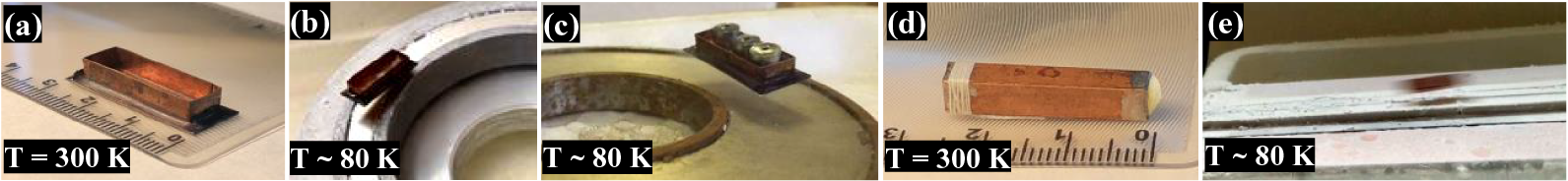
The temperature of the experiment was T ~ 80 K < T C, and it was maintained due to the fact that liquid nitrogen was poured directly into Sabot #1 (Figure 3(b)) and Sabot #2 had a polymer foam (Figure 3(c)) filled with liquid nitrogen. This is the very reason that basically determined the choice of the HTSC-sabot's geometry, namely, to prolong the time spent below the superconducting state transition during its transport with levitation (Figures 3(b), 3(c) and 3(e)).
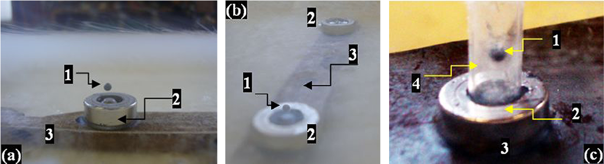
The second case being addressed is rigid, noncontact target positioning at a given point in space. The quantum locking (or pinning) forces can be either attractive or repulsive. They act to keep the HTSC in the same place in order for the magnetic flux inside its bulk to stay the same[ Reference Abrikosov 15 – Reference Ginzburg and Andryushin 17 ]. This is evident from the experiments in Figure 4, in which superconducting ceramics based on YBa2Cu3O7-x (YBCO) is used[ Reference Koresheva, Aleksandrova, Ivanenko, Kalabukhov, Koshelev, Kupriashin, Mitsen, Klenov, Osipov and Panina 9 ]. The suspension in Figure 4(c) cannot be explained by the Meissner effect because the Meissner force is strictly repulsive and dictates that a superconductor will always expel the magnetic field from its interior, and thus bend the magnetic field around it (see, for example, Figures 4(a) and 4(b)). The HTSC sample in Figure 4(c) does not fall down just due to the quantum locking phenomenon (Figure 4(c)).
Repulsion and attraction forces produced by interaction in an HTSC sample: 1 – a piece of YBCO ceramics with dimensions of 1.6 mm × 1.6 mm × 2.2 mm and a mass of 24 mg; 2 – PMG system. The HTSC sample can be suspended above the magnet (a), in the center of it (b) and below the magnet (c).
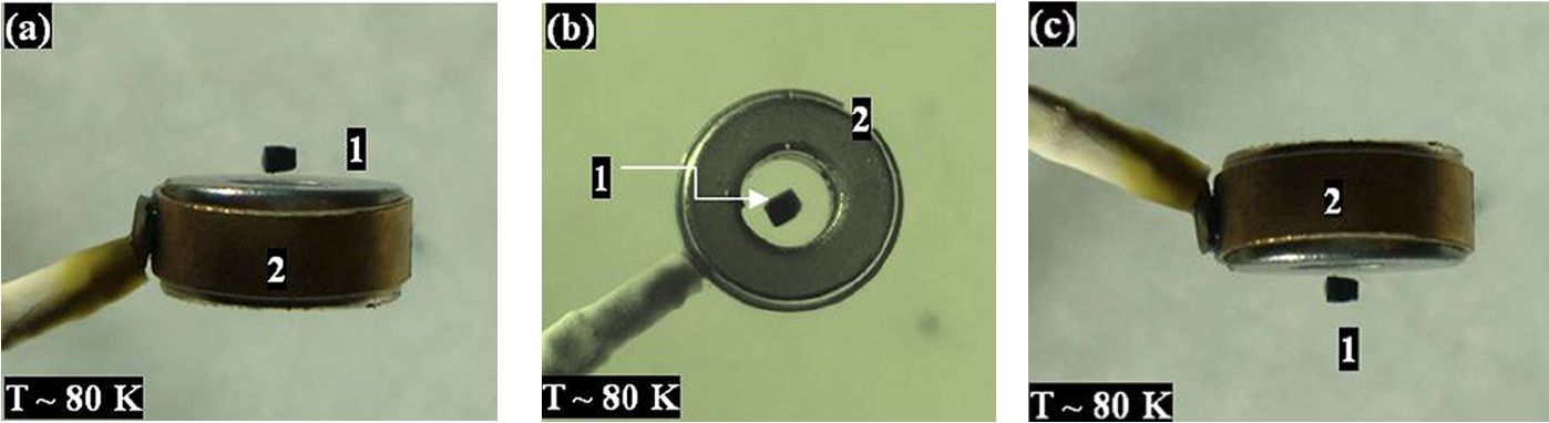
In this way, experiments with strongly pinned HTSCs and a special configuration of the PMG system display a high stability allowing the demonstration of striking effects, such as lateral or inverted suspension. The PMG system shown in Figure 4 consists of two ring magnets (OD = 15 mm, ID = 6 mm and assembly thickness 6 mm). The magnetic field on the NdFeB magnet surface is В max = 0.18 T. In general, for building different PMG systems we used standard permanent magnets in a variety of shapes and sizes (cast and sintered neodymium NdFeB ones, sintered samarium-cobalt SmCo ones and ferrite magnets manufactured by MIDORA Ltd.) and inserts made of soft magnetic materials.
For the ICF, quantum locking can be used for indirect-drive target assembly when the target is placed inside a small cavity called a hohlraum[ Reference Goodin, Alexander, Brown, Frey, Gallix, Gibson, Maxwell, Nobile, Olson, Petzoldt, Raffray, Rochau, Schroen, Tillack, Rickman and Vermillion 1 ]. It is a cylindrical container made from high-atomic-mass materials, such as gold and lead, with holes in the ends for laser beam entry. The first experiments modeling the quantum locking in the context of its promotion as a means of indirect-drive target assembly were made in Ref. [Reference Koresheva, Aleksandrova, Ivanenko, Kalabukhov, Koshelev, Kupriashin, Mitsen, Klenov, Osipov and Panina9].
Recently, new experiments on the assembly of a cylindrical container (made from glass for process visualization) and a magnetic holder have been successfully completed (Figure 5). In demo experimentation, an HTSC covering (YBCO-layer as a target carrier) was deposited onto the outer surface of a polystyrene (PS) shell (OD = 2 mm). The YBCO-layer is a composite from a viscous polymer having YBCO-micro-particles (OD = 10–50 μm). Practically, it is possible to use any other HTSCs that will satisfy most of the critical fabrication tolerances for target compression, and not only for the indirect-drive targets, but also for solving the layering and transport issues in the case of the direct-drive targets as well. Figure 5 is an illustration of some interesting possibilities of using HTSCs for ICF applications. Note that the target positioning remained unchanged until the moment when the YBCO-layer warms from T ~ 80 K back up to the transition temperature T C ~ 90 K. Moreover, attempts to displace the target at a distance of two target diameters from the center of the PMG system always led to its return to the starting position.
Quantum locking as a promising method for target assembly, known as ‘hohlraum’ targets: (a) PS shell (1) with a deposited YCBO-layer at T ~ 80 K, 2 – magnetic holder (NdFeB disk with OD = 15 mm, ID = 6 mm, d = 5 mm plus iron insert with OD = 6 mm, d = 5 mm), 3 – transport belt for magnetic holders placement; (b) holder spacing on the moving belt; (c) cylindrical container mounted onto the holder.
Thus, the quantum locking based on flux pinning effect can significantly improve the stability of the HTSC sample positioning. Here, the following question naturally arises: how can one transport such strongly pinned samples? The answer lies in the special construction of the PMG system. When HTSCs with high flux pinning capabilities are used, their motion and much of their motion stability are ensured by their placing in a magnetic field gradient. If the magnetic field has certain symmetry, HTSC movement is possible along the symmetry lines of the magnetic field. In all other directions the superconductor is locked. This opens a way to create different PMG systems with a magnetic track – linear or curved – for HTSC transport with levitation. In other words, if there is a strong magnetic field gradient in one direction and no gradient in others, the HTSCs can demonstrate a stable levitation above the magnetic track, being free to move back and forth along the track.
3 North–South–North magnetic track and main aspects of the linear PMG system
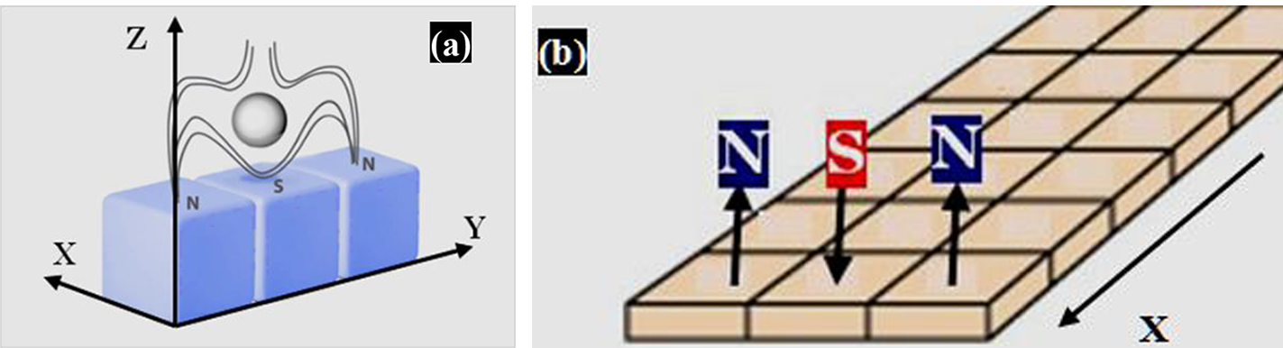
The idea behind the magnetic track construction to demonstrate a stable HTSC levitation was described in Ref. [Reference Ginzburg and Andryushin17]. It is the so-called ‘North–South–North’ (N-S-N) track, which is an assembly of many elementary blocks. Each elementary block (Figure 6(a)) is three bar magnets magnetized through the thickness and aligned anti-parallel to each other. This arrangement of polarities produces a considerably strong gradient of the magnetic field in the y-direction so that the process of HTSC quantum locking by height and orientation suppresses any arising undesirable vibrations in the system. If we build a track by connecting one elementary block with many others along the x-direction (Figure 6(b)), we get a desirable result: the magnetic field configuration will act to confine the HTSC in the y-direction while allowing motion in the x-direction. Thus, a map of the magnetic field lines above the N-S-N track forms a sort of ‘corridor with magnetic walls’ for noncontact HTSC transport.
Schematic diagram of the magnetic track construction: (a) N-S-N elementary block; (b) linear N-S-N magnets arranged in three rows forming a linear track (figure taken from Ref. [Reference Aleksandrova, Akunets, Bezotosnyi, Blokhin, Gavrilkin, Gromov, Ivanenko, Koshelev, Mitsen, Timasheva, Panina and Koresheva11]).
Practically, the bar magnets are mounted on an iron base to withstand the interaction between them and to create the magnetic track of a required fashion (using both linear and curve tracks) with a required acceleration length. To do this, the iron base thickness must be specially selected so that the magnets can be arranged with a minimal gap between them. This is due to the fact that such gaps located regularly along the acceleration track create magnetic gradients and reduce the HTSC-sabot velocity. This plays a significant role in the case of a small size of the accelerated objects. Taking into account that the outer diameter of the cryogenic target is about 4 mm[ Reference Goodin, Alexander, Brown, Frey, Gallix, Gibson, Maxwell, Nobile, Olson, Petzoldt, Raffray, Rochau, Schroen, Tillack, Rickman and Vermillion 1 ], we have built a magnetic track with a minimum number of gaps, or even without them.
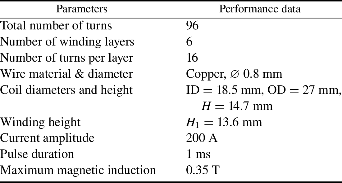
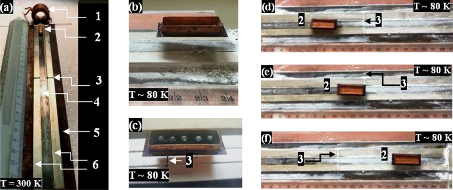
The general view of a prototype of a one-stage linear accelerator made at the LPI is presented in Figure 7(a). Experiments with this prototype enable one to study the basic behavior of stable levitation of the HTSC-sabot in the linear acceleration system. The PMG system has only one linear track, which consists of six rectangular NdFeB magnets having a size of 120 mm × 8 mm × 5 mm with the middle two covered with an iron plate (magnetic flux line collector) having a size of 240 mm × 8 mm × 1 mm. The PMG lies on an iron base with a size of 240 mm × 24 mm × 3 mm. The maximum magnetic field is B max = 0.42 T at the PMG side edges. The field just above the iron plate (position 4 in Figure 7(a)) is 0.33 T. The working parameters of the field coil are given in Table 2.
Field coil working parameters used in the HTSC-sabot acceleration experiments.
POP experiments for testing a one-stage linear accelerator: (a) general view of the PMG with only one gap at a length of 24 cm (1 – field coil, 2 – HTSC-sabot (300 K), 3 – gap between the magnets covered in the middle with an iron collector (4), 5 – iron base, 6 – permanent magnets); (b) Sabot #1 at the end of the magnetic track; (c) Sabot #1 during acceleration in the middle of the magnetic track, where the load capacity is six spherical polymer shells of about 0.6 mg each (tandem sabot); (d)–(f) freeze frames of the video recording of Sabot #2 acceleration (view from above).
The force F driving the HTSC-sabot in the x-direction (along the PMG) is given by the following formula[ Reference Landau and Lifshitz 16 ]:
 $$ \begin{align} F = \frac{\chi }{2{\mu}_0}\kern0.22em V\frac{\mathrm{d}B_{x}^2}{\mathrm{d}x},\end{align}$$
where μ 0 is the permeability of the vacuum, χ is the magnetic susceptibility of the HTSC material, V is the volume of the HTSC-sabot, x is the acceleration direction of the HTSC-sabot and Bx is the magnetic induction produced by the field coils of the propulsion system. The PMG field generated by the permanent magnets is directed normally to the x-direction that leads to the HTSC-sabot levitation due to the Meissner effect, which contributes to a levitation force F lev.
Note that the magnetic susceptibility is χ < 0 for any superconductor, and therefore the HTSC-sabot will be pushed out from the area of a stronger magnetic field.
As regards the magnitude of the driving force, data from specially designed experiments showed that the used field coil (its parameters are given in Table 2) can easily affect Sabot #1 (push it, see Figure 8) by the electromagnetic pulse generated during experiments.
Freeze frames of a Sabot #1 jump under the electromagnetic pulse action (B = 0.33 T, τ = 1 ms): (a) before the electromagnetic pulse, liquid nitrogen is poured into Sabot #1, where the observation time (frames a1–a4) is approximately 1 s; (b) initially the coil and Sabot #1 with a load capacity (copper plate inside it) were cooled with liquid nitrogen, and then an electromagnetic pulse was applied to the coil.
The levitation and guidance performance of the HTSC-sabot has been tested during its acceleration in the mutually normal magnetic fields, as shown in the schematic diagram (Figure 9(a)).
Experimental illustration of the characteristics of the HTSC-PMG maglev linear system: (a) schematic diagram, 1 – field coil, 2 – HTSC-sabot, 3 – PMG system, 4 – magnetic brake (if it is required by the experimental conditions, the system can have left- and right-hand brakes, or one of them, or none); (b) an option of the brake placement in the PMG system; (c) no co-linearity between elements 1 and 2; (d) and (e) collinear element arrangement; (f)–(h) oscillations of Sabot #1 between two brakes under mechanical drive pulse.

A magnetic pulse generated by the field coil (B1) drives the HTSC-sabot, and at the same time the PMG system (B2) ensures its levitation while driving. The magnets in the PMG-system are magnetized through the thickness, and are aligned through N-S-N. The magnets at the end are aligned with S up (Figure 9(b)). It works as a magnetic brake (В = 0.4 T) for reflecting the HTSC-sabot to the starting position practically with no energy loss. In doing so, a proper co-linearity between the axes of the field coil and HTSC-sabot is required (see the experiments in Figures 9(c)–9(e)). Note also that the HTSC-sabot motion can be launched both magnetically (e.g., with a field coil, see Figures 9(c)–9(e)) and mechanically (e.g., with a simple mechanical ‘push’, see Figures 8(f)–8(h)).
Important is the fact that the scheme in Figure 9(a) can be also used to conduct a study with different HTSC-sabots to address the issues of repetition rate experiments (with a magnetic brake on the right-hand side) and mechanical overloads under acceleration.
Our work has recently been extended to upgrade the existing linear acceleration scheme for reaching a higher level of co-linearity between the coil and sabot axes. In the POP experiments Sabot #1 was used. The experiments have shown that even with rather modest parameters of the field coil (Table 2) but with correct co-linearity, the HTSC-sabot velocity can be increased almost by an order of magnitude: from 10 cm/s up to 1.25 m/s, and in the process, the HTSC-sabot maintains its velocity along the entire track length, equal to 24 cm (see Figure 7).
These experiments are of great importance because such a linear accelerator can be used in high-velocity applications in that it allows a convenient spacing of the multiple field coils and thus building a multiple-stage linear (MSL) accelerator. This approach is evaluated with respect to the technical feasibility of the corresponding MSL components: HTSC-projectile acceleration a, acceleration length L a and the number of the field coils N in the propulsion system. The goal is to achieve the required injection velocities (V inj = 200–400 m/s) without exceeding acceleration limitations (see Table 1).
We consider the possibilities of its building by using an advanced option of the HTSC-sabot construction: 2G-HTSC-Tapes-Housing + MgB2-Coils (Figure 1(a)). The critical temperature of MgB2 is T C = 39 K, which meets the temperature tolerance for ICF targets (T ~ 18 K, see Table 1). It possesses high values of the critical current J C at a rather small external magnetic field B 0 [ Reference Aleksandrova and Koresheva 7 ] (Table 3). In the case of the MSL accelerator, the acceleration lengths can be estimated by using the following relations[ Reference Aleksandrova, Koshelev, Nikitenko, Timasheva and Koresheva 12 ]:
 $$\begin{align}\left\{\begin{array}{l}{L}_{\mathrm{a}} = \frac{\pi }{2}{V}_{\mathrm{inj}}\frac{R_{\mathrm{FC}}}{R_{\mathrm{S}\mathrm{C}}}\frac{M_{\mathrm{PR}}}{F_{\mathrm{pin}}{V}_{\mathrm{S}}},\\[3pt] {}{F}_{\mathrm{pin}} = {J}_{\mathrm{C}}\left({B}_0,{T}_{\mathrm{S}}\right)\times {B}_0,\end{array}\right.\end{align}$$
MSL accelerator parameters in the case of V inj = 200 m/s (values are specified for driving coils from MgB2 at T S = 20 K).
where M PR is the mass of the HTSC-projectile, R FC is the field coil radius, R SC is the MgB2-coil radius (with a margin R FC/R SC = 5), F pin is the pinning force density and J C is the critical current density, which depends on the external magnetic field in the coil center B 0 and the temperature T S of HTSC.
Using the MgB2 measurements[ Reference Goldacker, Schlachter, Zimmer and Reineret 13 , Reference Antonov and Zaytcev 14 ] in terms of B 0 and J C, we calculated the acceleration parameters at T S = 20 K for V inj = 200 m/s and M PR = 0.5 g. A reactor-scaled cryogenic target has the diameter of approximately 4 mm and the mass of M T ~ 4.5 mg (M T << M PR), and it can be formed by the FST layering method[ Reference Aleksandrova and Koresheva 7 ]. The obtained results are presented in Table 3.
According to these results, at a = 400g the injection velocity V inj = 200 m/s is reached at a 5 m track length under the following parameters of the propulsion system: B 0 = 0.25 T, J C = 5000 A, N = 200. Significant reduction of the MSL accelerator dimensions and the number of the field coils can be obtained by doubling the magnitude of the magnetic field (B 0 = 0.5 T) and thus increasing the HTSC-sabot acceleration up to a = 640g.
Taking into account the results of our estimations (see Table 3) and considering that 200 m/s is a lower velocity limit (see Table 1), to achieve higher values of V inj becomes a problem for moderate acceleration lengths at the lower acceleration limit.
Figure 10 confirms this statement: for velocity V inj = 400 m/s the acceleration length becomes 20 m at a < 500g. If the targets have adequate mechanical robustness and protection, another acceleration scenario can be implemented: V inj = 400 m/s, L a = 10 m, a = 800g, which in turn leads to a considerable growth of on-target mechanical overloads but still less than 1000g.
Acceleration length L a for two values of the HTSC-sabot velocity: 200 and 400 m/s.

Thus, for the MSL accelerator, top injection velocities (~400 m/s) lead either to long acceleration lengths and a significant number of the field coils, or to a sharp acceleration growth. A way to minimize these problems is to develop a more compact design of the target accelerator, and wherein to optimize its performance and enhance its reliability and safety to contribute to reducing the target production costs.
4 A next generation PMG system of a cyclotron type
These challenging requirements can be met using a next generation PMG system of the cyclotron type. The characteristics of the permanent magnets composing the guideway are very important in terms of levitation force and stability, and therefore we consider this issue in more detail.
We start with a round PMG system (Figure 11), which is a combination of two elements: a permanent magnet – axially magnetized NdFeB ring – and an iron base (Figures 11(a) and 11(b)). The iron base shaped into a pole piece (iron pot) guides and concentrates the magnetic flux onto the working surface (Figure 11(c)).
A round PMG system to provide a stable cyclic motion of the HTSC-sabot about the Z-axis: (a) and (b) PMG system design; (c) overview of the ring magnet placed in the iron pot; (d) magnetic field mapping on the ring magnet surface.

Special attention should be paid to Figure 11(d), which maps the magnetic field configuration by means of a magnetic field viewing (MFV) film also known as green MFV film. It allows one to easily view the magnetic fields and pole patterns on a magnet or magnetic assembly surface. Figure 11(d) demonstrates a circular symmetry of the magnetic field of the PMG system. This means that the magnetic flux does not change along the circular track, allowing the HTSC-sabot to move around freely. In all other directions the HTSC-sabot will be locked due to the magnetic field gradient across the track (white line in Figure 10(d)).
The z-component of the magnetic field contributing to the levitation height is given in Figure 12. A magnetometer based on the DKhK-0.5A Hall probe with a sensitivity of 280 mV/T is used. The measuring range is ±250 mT, the absolute error is ±5 mT and the positioning accuracy of the sensitive element is 0.1 mm. The plateau on the blue curve for z = 1 mm is due to the limitation in the magnetic field magnitude, which can be measured by DKhK-0.5A.
The z-component of the magnetic field (Bz ) versus radius (r) above the round PMG at various heights: blue – 1 mm, violet – 4 mm, aquamarine – 7 mm, red – 10 mm, green – 11 mm and black – 16.5 mm. Between 1 and 7 mm above the track, the gradient is still very strong to control the HTSC-sabot trajectory.

First of all, our work was focused on experiments with mechanical propulsion in order to most easily investigate such parameters of round PMG system as guidance, levitation and stability (Figures 13–16). In doing so, the HTSC-sabot initially needs a small push to get going, and then it will maintain its velocity until the moment when its temperature approaches the transition temperature T C ~ 90 K. The following set of the experiments was made, using the following.
-
(1) Different sabot geometries with an additional loading (see, for example, Figures 3(c) and 7(c)) and without it (Figures 13–16).
-
(2) Different sabot orientations during the acceleration to study stability issues (Figure 13).
-
(3) Different sabot trajectories along the inner and outer circular lines of the round PMG system at different levitation heights: Figures 14(a) and 14(b) – the levitation height is 6 mm, and Figures 14(c)–14(e) – the levitation height is 3 mm. A height of approximately 10 mm is still possible, but the levitation is not stable anymore. The choice of optimal height is mainly limited by two facts: above by the magnetic field distribution at the given levitation height, and below by the fact that small levitation heights can cause some magnetic friction to the track.
-
(4) Different driving pulses to realize different HTSC-sabot velocities due to a mechanical ‘push’ of varying strength (the velocities are around 0.15 m/s (Figures 14(a) and 14(b)) to 0.8 m/s (Figures 14(c)–14(e)). After an initial ‘push’, the HTSC-sabot trajectory remained unchanged during rotation. The number of turns at the same levitation height depends on the time before the HTSC warms from T ~ 80 K back up to the transition temperature T C ~ 90 K. To avoid heating, insulation materials and some of their combinations were used in the experiments: liquid nitrogen, aluminum foil and polymer foam saturated with liquid nitrogen. Note also, if the temperature is far from the value of T C, the levitation drift is absent (the gap between the HTSC-sabot and PMG system is kept unvarying with time).
Quantum locking based on the flux pinning effect makes the HTSC-sabot orientation fixed in space so that it will not re-orient itself without any external action (the HTSC-sabot temperature is ~ 80 K).
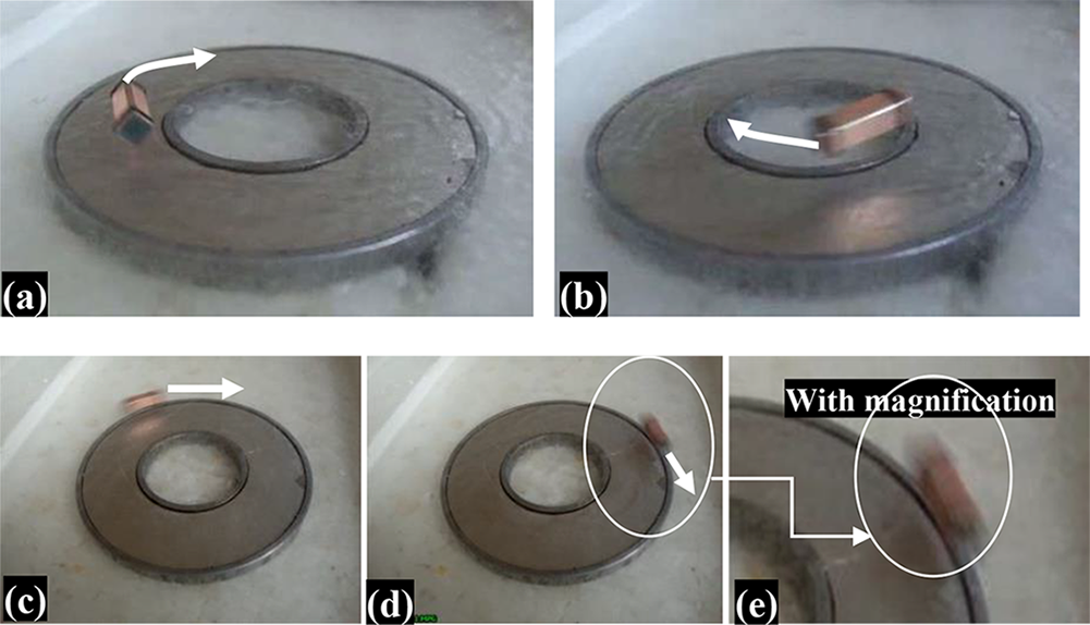
Freeze frames of the Sabot #2 rotation along a fixed trajectory (T ~ 80 K): (a) and (b) near the internal PMG border (the levitation height is 6 mm, the average HTSC-sabot velocity is 0.15 m/s); (c)–(e) in the external PMG border (the levitation height is 3 mm, the average HTSC-sabot velocity is 0.8 m/s).
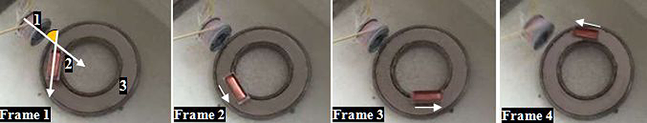
Freeze frames of the rotation movement of Sabot #1 along a changing trajectory (T ~ 80 K): (a) starting from the PMG middle (frame 1), Sabot #1 gradually picks up its velocity and shifts due to the centrifugal force to the outer PMG border (frame 5); (b) frames 6–8 correspond to the last few turns, and then Sabot #1 stalls from the trajectory when its velocity becomes equal to 1.48 m/s.

The round PMG system with magnetic propulsion (T ~ 80 K): 1 – field coil (the drive pulse is generated in the sabot position corresponding to frame 1), 2 – Sabot #1, 3 – NdFeB ring magnet.
Other experiments have been centered on attempts to model the cyclotron acceleration process with an increase in external influence on the HTSC-sabot. In Figure 15 the HTSC-sabot moves along a trajectory in the form of an unwinding spiral going away from the center of the PMG system. This is due to the fact of changing the PMG system inclination to the beat of the HTSC-sabot rotation. Upon reaching a certain velocity V out (which depends on the PMG field), the HTSC-sabot leaves its trajectory, which leads to derailment in the outer border of the track. In our case it happens at a velocity of V out = 1.48 m/s. We emphasize that the PMG field plays the role of a kind of ‘magnetic wall’ so that the HTSC-sabot experiences the magnetic force due to which it moves in a circular trajectory before feeding a new portion of energy.
These results have shown that implementation of the cyclotron acceleration process is possible. A practical opportunity opens up when passing from mechanical to magnetic propulsion (Figure 16). However, in this case (compare Figures 9(a) and 16) it is difficult to achieve a proper co-linearity between the axes of the field coil and HTSC-sabot, especially if installing the field coil on a round track. Therefore, we have proposed a new track topology for ICF target acceleration, as presented in Figures 17–19.
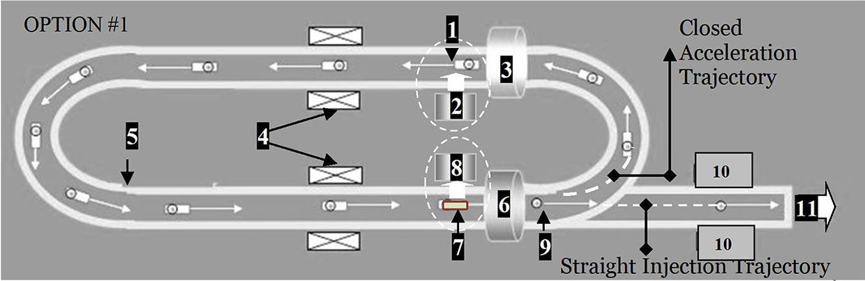
An option of the cyclic HTSC-maglev accelerator for target delivery at the laser focus: 1 – HTSC-projectile (HTSC-sabot + target), 2 – TLS, 3 – start (input) coil, 4 – field coils, 5 – magnetic rail, 6 – brake (output) coil, 7 – used HTSC-sabot, 8 – SCS, 9 – target after separation from the HTSC-sabot, 10 – tracking system; 11 – to the reaction chamber. In this scheme, the start (3) and brake (6) coils can play the role of the field coils (4), which simplifies the accelerator design. The HTSC-sabot (7) can be reused again and again in the target delivery system.
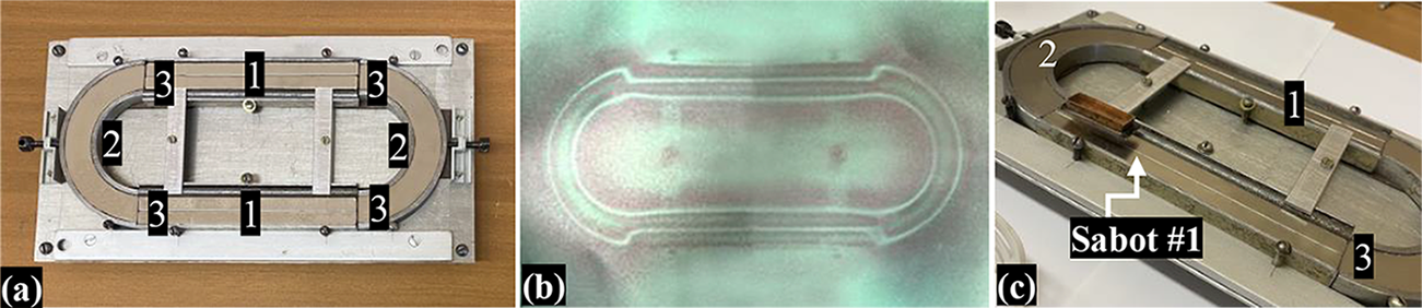
An oval-shaped PMG with a length of 22 cm and a width of 9.5 cm was build up from four individual tracks to alternate acceleration (track 1) and rotary functions (track 2), having four gaps between them (3): (a) general view of the PMG system; (b) magnetic field mapping by MFV film; (c) Sabot #1 (with liquid nitrogen inside, T ~ 80 K) at the output of the round track.
First experiments with an oval-shaped PMG without any gaps (‘one-piece’ design or non-composite magnet): (a) stable levitation of Sabot #2 (T ~ 80 K, HTSC-sabot axis along the track); (b) magnetic field mapping by MFV film; (c) stable levitation of Sabot #1 (T ~ 80 K, HTSC-sabot axis across the track).

Figure 17 shows schematically an option of a cyclotron HTSC-maglev accelerator with an oval-shaped PMG that has linear tracks with field coils and round tracks to provide rotary functions. Such a configuration is designed to place the HTSC-sabot in such a cyclic trajectory when it gains the required injection velocity V inj moving in a limited PMG[ Reference Aleksandrova, Koresheva and Koshelev 5 ].
The HTSC-maglev cyclotron accelerator has a modular design, the main components of which are as follows.
-
• Projectile loading module: (a) for loading the HTSC-projectile (1) at the starting point by a target loading system (TLS) (2), which operates using special guiding tubes as proposed and examined in Ref. [Reference Koresheva, Aleksandrova, Koshelev, Nikitenko, Timasheva, Tolokonnikov, Belolipetskiy, Kapralov, Sergeev, Blazevic, Weyrich, Varentsov, Tahir, Udrea and Hoffmann20] for manipulation of cylindrical cryogenic targets required for the experiments at the Facility for Antiproton and Ion Research; (b) for launching the HTSC-projectile in the PMG by a start coil (3) with an initial velocity v 0.
-
• Cyclotron acceleration module: for accelerating the HTSC-projectile in a pulsed magnetic field of the field coils (4) located on the linear tracks. In the process, the field coils generate the magnetic traveling waves that act on the HTSC-sabot. As a result, the HTSC-projectile moves along the closed magnetic rail (5) and gradually gains its velocity up to the required value V inj. To control the HTSC-projectile trajectory, a special magnetic gradient in the PMG cross-section and HTSC materials with the strong pinning capabilities are totally relevant.
-
• Projectile separation module: for separating the HTSC-sabot and target with the brake coil (6). In the process, the HTSC-sabot drops its velocity during its deceleration in the magnetic field of coil (6), while the target keeps its velocity moving by inertia (the target is non-magnetic and it is not affected by the magnetic field). The used HTSC-sabot (7) is removed from the PMG by a separation coil (not shown in Figure 17) with a pulsed, repetitively cycled field, and then it is directed to a sabot collection system (SCS) (8). The target (9) enters a precision system (10) for in-flight tracking of its parameters (quality, velocity and trajectory) with a high-resolution Fourier holography method[ Reference Koresheva, Osipov and Aleksandrova 21 , Reference Aleksandrova, Koresheva, Koshelev, Krokhin, Nikitenko and Osipov 22 ]. Note that there is another OPTION #2 when the separation module is located outside the acceleration trajectory, but directly on the injection one before the tracking system (10). Position (11) corresponds to the target injection to the reaction chamber. The issues of target monitoring and trajectory correction during its flight in the reaction chamber, including strict time synchronization with a laser pulse, were considered, for example, in Refs. [Reference Mori, Ishii, Hanayama, Okihara, Kitagawa, Nishimura, Komeda, Hioki, Motohiro, Sunahara, Sentoku, Iwamoto, Sakagami, Miura and Johzaki3,Reference Kassai and Tsuji23].
Note also that our experiments (see the previous sections) with strongly pinned HTSCs and a special configuration of the PMG system display a high stability, allowing the demonstration of lateral, vertical (gravitational injector[ Reference Aleksandrova, Akunets, Bezotosnyi, Blokhin, Gavrilkin, Gromov, Ivanenko, Koshelev, Mitsen, Timasheva, Panina and Koresheva 11 ]) or inverted positions of the plane of the maglev delivery system relative to the target chamber.
Currently, our work is focused on the cyclotron acceleration module to define development pathways and potential engineering solutions that represent a promising technological application for ICF target delivery. We have started with the HTSC-sabot acceleration using only several field coils and a limited magnetic rail consisting of an oval-shaped loop. It was built up from four individual tracks to separate acceleration and rotary functions: two linear and two curved tracks with four gaps between them (Figure 18). The curved tracks are a part of the ring magnet, similar to the magnet shown in Figure 11. Using one field coil (see Table 2), the velocity of the HTSC-sabot is approximately 1 m/s per one round[ Reference Aleksandrova, Koresheva and Koshelev 5 ].
Recently, another line of research dealing with PMG systems with a magnetic rail without any gaps has been rapidly developed (the so-called ‘one-piece’ design or non-composite magnet, as shown in Figure 19). This is an oval-shaped magnet that is made from NdFeB alloy, sintered, with an axial magnetization and having a size of 140 mm × 64 mm × 14 mm. The magnet also has an anti-corrosion cover Ni-Cu-Ni, its weight is 245 g and the magnetic field is B max = 1.47 T, which is 3.5 times more than in the case of the linear PMG (0.42 T at the PMG side edges). To assess future prospects, it is very important to study the stability of the HTSC-sabot motion, which is directly related to the safe operation of the proposed PMG system. First demonstration experiments (Figure 19(c)) have shown that this very simple combination ‘one-magnet-plus-HTSC-sabot’ displays a high stability of the levitation and acceleration processes, and can be considered as an efficient approach for optimizing the track unit structure in the future HTSC-maglev cyclotron accelerator.
In this regard, it becomes urgent to study the next technologically important range of V inj = 10–50 m/s. Below we specify the necessary requirements for the HTSC materials and PMG fields for a proposed cyclotron acceleration module. Firstly, for a given velocity V inj, we need to estimate the parameters of the curved tracks of the PMG system needed to perform the rotary functions, namely, the radius R of the curved tracks and the magnetic field distribution along the radius. We consider the simplest case R being a constant as it was in our experiments (Figure 18). A study of the effect of more complex shapes of the transition curve between two linear tracks on the dynamic levitation performance of the HTSC-sabot (including suppression of the external disturbances, if any) is planned for the near future.
While moving circularly, the HTSC-sabot interacts with the PMG, generating a guidance repulsive force F r to balance the centrifugal force F c. Using Equation (1), the mechanical equilibrium equation of the HTSC-sabot running stably on the circular PMG track is given by the following:
 $$\begin{align}{F}_{\mathrm{r}} = \frac{\chi }{2{\mu}_0}V\frac{\partial {B}^2}{\partial r} = m\frac{V_{\mathrm{inj}}^2}{R} = {F}_{\mathrm{c}},\end{align}$$
where R is the track radius and m is the HTSC-sabot mass. Equation (3) can be written in a form convenient for further analysis:
 $$\begin{align}{B}_{\mathrm{r}}\frac{\mathrm{d}B_{\mathrm{r}}}{\mathrm{d}r} = \frac{\mu_0}{\chi}\kern0.22em \frac{m}{V}\frac{V_{\mathrm{inj}}^2}{R}.\end{align}$$
Now let us introduce a parameter $\eta$
characterizing the HTSC material properties:
$\eta$
characterizing the HTSC material properties: $\eta = \rho /\chi,$
where
$\eta = \rho /\chi,$
where $\rho = m/V$
. Then Equation (4) takes the following form:
$\rho = m/V$
. Then Equation (4) takes the following form:
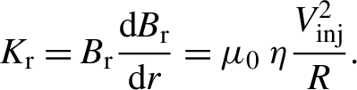 $$\begin{align}{K}_{\mathrm{r}} = {B}_{\mathrm{r}}\frac{\mathrm{d}B_{\mathrm{r}}}{\mathrm{d}r} = {\mu}_0\;\eta \frac{V_{\mathrm{inj}}^2}{R}.\end{align}$$
Due to the permeability of the vacuum, μ
0 = 4π × 10–7 N/A2 is constant, and the values of η and R determine the value of K
r, that is, magnetic force field (B
r × dB
r/dr) along the track radius for each individual V
inj. The results for K
r are shown in Figure 20 through calculations for different values of the parameter $\eta$
under the given injection velocities. It is clearly seen that in strong magnetic fields of B = 1–3 T the magnetic field gradients of such order can be realized only at small distances, which limits the linear dimensions of the accelerated body to values of the order of a few centimeters. As noted above, the mass of a reactor-scaled target is approximately 4.5 mg and its outer diameter is approximately 4 mm, which are very much suitable conditions for maglev target acceleration. Regarding the accelerator dimensions, the obtained results for V
inj = 50 m/s are evidently applicable, starting with the smallest value R = 1 m: point A1 – the value of B
r = 1125 T2/m, which can be written, for example, as B
r = 2 T × 0.56 T/mm; point A2 − B
r = 225 T2/m or B
r = 1 T × 0.225 T/mm.
$\eta$
under the given injection velocities. It is clearly seen that in strong magnetic fields of B = 1–3 T the magnetic field gradients of such order can be realized only at small distances, which limits the linear dimensions of the accelerated body to values of the order of a few centimeters. As noted above, the mass of a reactor-scaled target is approximately 4.5 mg and its outer diameter is approximately 4 mm, which are very much suitable conditions for maglev target acceleration. Regarding the accelerator dimensions, the obtained results for V
inj = 50 m/s are evidently applicable, starting with the smallest value R = 1 m: point A1 – the value of B
r = 1125 T2/m, which can be written, for example, as B
r = 2 T × 0.56 T/mm; point A2 − B
r = 225 T2/m or B
r = 1 T × 0.225 T/mm.
The magnetic force field K r versus track radius for different injection velocities: 1 − η = 1.0 × 10³ g/cm3, Vinj = 200 m/s; 2 − η = 2.5 × 10 3g/cm3, Vinj = 100 m/s; 3 − η = 4.5 × 10³ g/cm3, Vinj = 50 m/s.
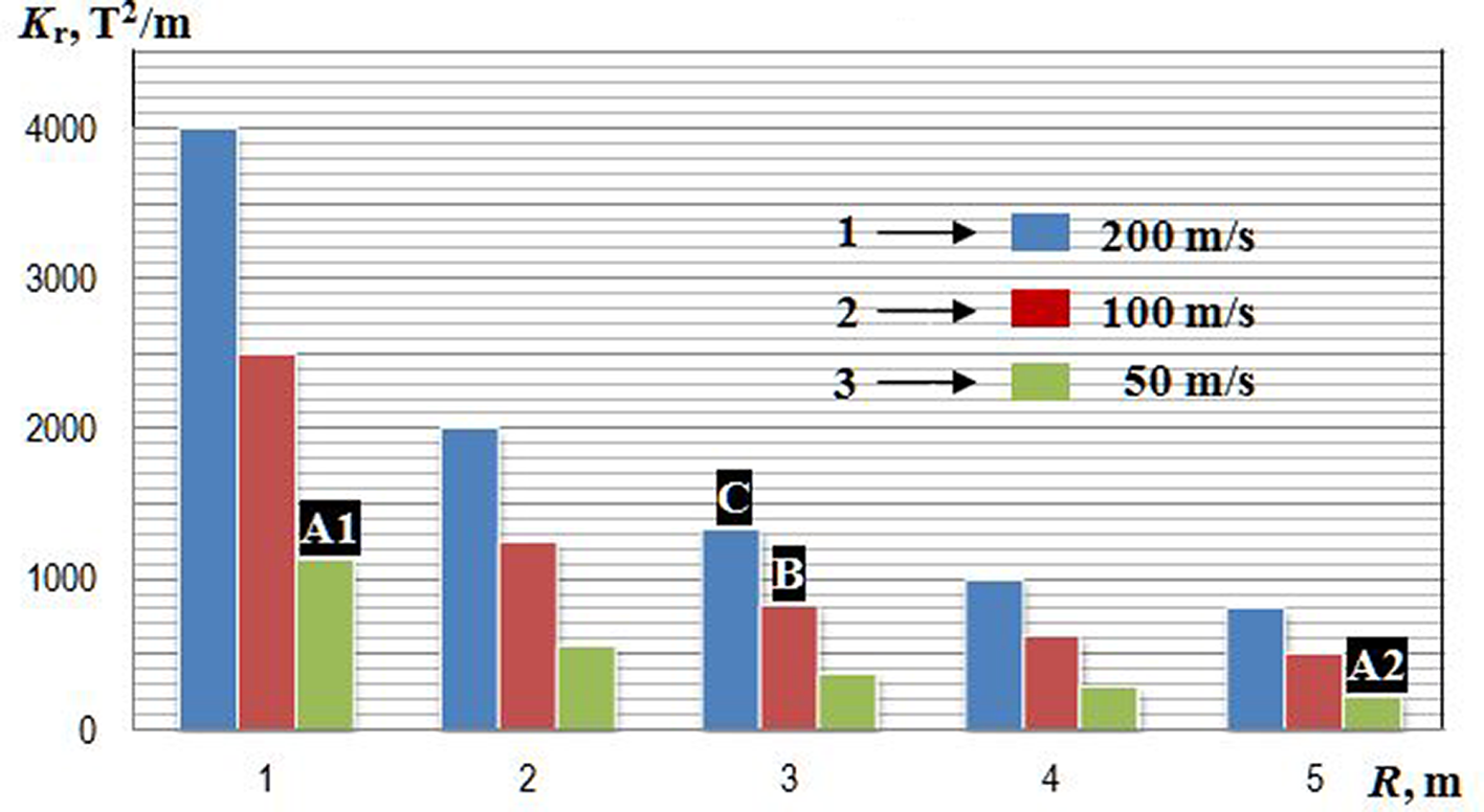
For velocities of 100 and 200 m/s, we write similar values for R = 3 m: point B − B r = 833 T2/m or B r = 2 T × 0.416 T/mm; point C − B r = 1333 T2/m or B r = 3 T × 0.67 T/mm.
To improve the obtained results, especially for V inj > 100 m/s and track radius R < 3 m, it is necessary to select HTSC materials with less density ρ and larger susceptibility χ (i.e., to reduce the parameter η, see Equation (5)). We consider already tested HTSC samples, as well as evaluate promising developments that are more suitable to a high-velocity running of the HTSC-sabot. Figure 1(b) shows an HTSC-housing made of bulk YBCO manufactured in the LPI by the method of solid-phase reactions[ Reference Koresheva, Aleksandrova, Ivanenko, Kalabukhov, Koshelev, Kupriashin, Mitsen, Klenov, Osipov and Panina 9 ], for which we have the measured values of the magnetic susceptibility[ Reference Aleksandrova, Akunets, Bezotosnyi, Blokhin, Gavrilkin, Ivanenko, Koresheva, Koshelev, Mitsen and Panina 10 ] both at temperatures of experimentation T exp ~ 80 K and at temperatures of target injection T inj ~ 17 K (which must be less than the target temperature at the laser shot T ~ 18 K). The values of the lower and upper critical fields are μ 0 H C1 = 3 mT at T = 17 K and μ 0 H C2 > 45 T at 0 K, respectively. The properties of the YBCO samples were measured in Ref. [Reference Aleksandrova, Akunets, Bezotosnyi, Blokhin, Gavrilkin, Ivanenko, Koresheva, Koshelev, Mitsen and Panina10] using a multifunctional automated measuring complex PPMS-9 (Quantum Design Ltd.), which provides options to measure the magnetic moment, both in static and dynamic modes, with an accuracy of 2.5 × 10⁻⁵ emu. The maximum value of the magnetic field reaches 9 T under field uniformity in the sample region, which is no worse than 0.01%. The temperature range available for measurements is 0.35–400 K with a temperature control no worse than 0.01 K. It has been found that in the fields we are interested in (1–3 T) the measured values of the magnetic susceptibility at T inj ~17 K (χ ~ 0.9 × 10⁻³) are almost an order of magnitude more than at T exp ~ 80 K (χ ~ 10−4). The density of YBCO samples was ρ = 4–6 g/cm3, so that minimal value η = 4.4 × 10³ g/cm3. This value accurately reflects Case 3 in Figure 20.
Therefore, our near-term goal is to study the cyclotron acceleration process during gradual increasing of the HTSC-sabot velocity in the next technologically important range, that is, up to 50 m/s.
As for V inj = 100–200 m/s, it is timely to put the question of developing material options and technologies for next generation HTSCs with reduced density and increased magnetization. With the objective to improve superconducting properties, one should pay attention to works that suggest strategies to overcome present limitations focusing on the development of engineering solutions for novel HTSC materials. A technology has been developed for the production of nanostructured ceramics based on YBCO of various densities (from 6.1 to 2.4 g/cm3) with a high proportion of the superconducting phase, optimally saturated with oxygen and with pinning centers from nanoparticles of parent element oxides[ Reference Gadzhimagomedov, Alikhanov, Emirov, Palchaev, Murlieva, Rabadanov, Sadykov, Khamidov and Hashafa 24 ]. Besides, several groups of porous superconductors have been investigated. The pores in such materials allow coolant penetration, efficient heat dissipation and stable operation. A review of studies of superconductors with porosities above 50% is presented in Ref. [Reference Gohfeld, Koblishka and Koblishka-Veneva25].
As for V inj = 400 m/s, theoretically it is predicated that the highest velocity of the HTSC maglev vehicle is up to 2900 km/h (~800 m/s)[ Reference Zhou, Zhao, Li, Cui, Hsieh, Zhang, Guo and Zhao 26 ]. Practically, different efficient schemes[ Reference Antonov and Zaytcev 14 ] for optimizing the superconducting levitation and guidance, including a side-suspended HTSC-PMG maglev circular line system[ Reference Zhou, Zhao, Li, Cui, Hsieh, Zhang, Guo and Zhao 26 ], have been developed as a strategy to perform a search of the optimal options for PMGs and HTSC materials. The main advantage of the proposed schemes is that high-velocity operation and good acceleration stability can be achieved without the need for any special control, which minimizes the maintenance costs and can lead to many other applications.
Closing this section, we note that at this stage of research our goal was to show the possibility of an alternative approach to ICF target delivery in comparison with conventional ones (such as pneumatic, electromagnetic, electrostatic injector concepts). They are useful for initial demonstrations, but an advanced noncontact accelerator is desirable in the long run. To this end, we have designed and tested linear and cyclic PMG systems to illustrate the operational principle behind the HTSC-maglev accelerator for noncontact ICF target delivery that succeeded in overcoming friction and demonstrated a way to use propulsion energy more efficiently.
5 Summary
Noncontact target acceleration is one of the key technologies to realize target delivery to the ICF reactor. This paper presents the conception, simulation and experimental evaluation of noncontact HTSC-sabot acceleration in different PMG systems. We found that the parameters of the permanent magnets composing the PMG system are very important for their performance in terms of levitation force and target trajectory control. HTSCs are potentially good sabot materials for operation with ICF targets because of their suitable critical temperatures (~90 K) and large stability due to the flux pinning effect in the HTSCs.
The HTSCs used in our experiments are high-pinning-Type-II superconductors to enable sufficient levitation and guidance forces, and stability. Depending on PMG system design, this allows one to provide a three-dimensional locking of HTSCs at a given point in space (a promising method for target assemblies known as ‘hohlraum’ targets), or to provide a stable levitation of the HTSC-sabots (locking by height and orientation) during their acceleration over a PMG system. If necessary, the pinning effect can be enhanced by knowingly introducing special defects – pinning centers to the HTSC sample[ Reference Abrikosov 15 – Reference Ginzburg and Andryushin 17 ], which prevent the free movement of the magnetic vortices, and thus energy dissipation, wherein the main task is to determine the optimal size and shape of the pinning centers as well as their number and location in the sample.
This paper also highlights our recent experimental progress toward using different PMG systems to work not only in a linear acceleration scheme but also in a cycled mode to achieve significant reduction of the accelerator dimensions.
The results of our experimental and theoretical modeling have shown that the linear HTSC-maglev accelerator can be built for the entire range of injection velocities. For the top velocity V inj = 400 m/s, the acceleration length is L a = 20 m at a < 500g. If the targets have adequate mechanical robustness and protection, another acceleration scenario can be implemented: V inj = 400 m/s, L a = 10 m, a = 800g (<1000g, see Table 1).
The concept of a cyclotron HTSC-maglev accelerator is discussed as well, and the first acceleration experiments were carried out successfully. Currently, using only one field coil the HTSC-sabot velocity is approximately 1 m/s per one round in an oval PMG of 22 cm × 9.5 cm. Our study has shown that future perspectives to create the cyclotron target accelerator are primarily associated with a proper choice of HTSC materials (reduction of the parameter η) and PMG system construction in which the magnetic track has an oval-shaped rail consisting of linear and curved parts. The linear parts take care of the propulsion system alignment with the HTSC-sabot axis, and the curved parts provide a round-turn function to close the trajectory and realize a gradual gain of the target velocity. The PMG system magnets must have the proper adjustment on the track so as to minimize the gaps between them and to maximize the N-S-N cross-sectional gradient of the magnetic field to provide a large lateral stability of the HTSC-sabot trajectory. Current results obtained can provide a design reference for optimizing and constructing an HTSC-PMG system with higher performance and higher velocity range.
Basically, the research findings demonstrate the ability of the HTSC-maglev technology for noncontact target acceleration under the protection of an HTSC-sabot. The self-stabilizing effect of the developed HTSC-PMG systems is the main advantage in comparison to all other levitation systems. Still, in this context, it should be emphasized that there are convincing arguments to consider different schemes for realizing the acceleration process: linear, cyclotron and combined. In addition, the HTSC-maglev concept is compatible with the concept of using free-standing and line-moving targets[ Reference Aleksandrova, Koresheva and Koshelev 5 ] for fueling of a laser-driven ICF reactor. Advantages here are the noncontact transport and thus the lack of wear and mechanical friction. This increases efficiency and reduces the maintenance cost, which in turn prolongs the service life of the target delivery system, especially for its operation under HRR conditions.
All this indicates that the HTSC-maglev concept can overcome the limitations of conventional acceleration technologies and become now one of the leading candidates for meeting the strict requirements of future ICF experiments.
Acknowledgments
This work was supported by the IAEA within project No. 24154, ‘Modeling of the Optics Degradation under Ionizing Radiation and Mass Fabrication of Low Aspect-Ratio Targets for a Repetition-Rate IFE Facility’, as well as within the framework of the LPI State Task and under the program of the Presidium of the Russian Academy of Sciences.
The authors are grateful to A. I. Nikitenko for help in processing the experimental data.


 Open access