


Introduction
High-entropy alloys (HEAs) have attracted significant research interests due to their excellent strength, ductility, and radiation resistance [Reference Li, Pradeep, Deng, Raabe and Tasan1, Reference Gludovatz, Hohenwarter, Catoor, Chang, George and Ritchie2, Reference Zhang, Stocks, Jin, Lu, Bei, Sales, Wang, Béland, Stoller and Samolyuk3, Reference Zhang, Zuo, Tang, Gao, Dahmen, Liaw and Lu4, Reference Cantor, Chang, Knight and Vincent5, Reference Gao, Yeh, Liaw and Zhang6]. These superior properties make HEAs suitable for a variety of applications, especially as potential structural materials for advanced nuclear energy systems [Reference Zinkle and Was7, Reference Allen, Busby, Meyer and Petti8, Reference Zinkle and Busby9, Reference Yvon and Carré10]. This potential has been boosted by suppressed dislocation formation and negligible hardening [Reference El-Atwani, Li, Li, Devaraj, Baldwin, Schneider, Sobieraj, Wróbel, Nguyen-Manh, Maloy and Martinez11], enhanced strength without loss of ductility [Reference Moschetti, Xu, Schuh, Hohenwarter, Couzinié, Kruzic, Bhattacharyya and Gludovatz12], great phase stability [Reference Xia, Gao, Yang, Liaw and Zhang13], and suppressed helium bubble growth [Reference Chen, Zhao, Sun, Tai, Sheng, Zhao, Yeli, Lin, Liu and Kai14, Reference Yang, Ge, Zhang, Xiong, Jin, Zhou, Shao, Zhang, Zhu, Zheng and Ma15] in irradiated HEAs. As a major threat to the structural stability of nuclear materials, void swelling in HEAs has been widely investigated. Previous studies generally revealed no void formation [Reference Kumar, Li, Leonard, Bei and Zinkle16, Reference Yang, Xia, Guo, Hu, Poplawsky, Sha, Fang, Yan, Wang and Li17, Reference Yang, Guo, Poplawsky, Li, Wang, Li, Hu, Crespillo, Yan, Zhang, Wang and Zinkle18] or suppressed void growth [Reference Yang, Lu, Velisa, Jin, Xiu, Zhang, Bei and Wang19, Reference Lu, Niu, Chen, Jin, Yang, Xiu, Zhang, Gao, Bei and Shi20, Reference Yang, Lu, Jin, Crespillo, Zhang, Bei and Wang21] at elevated temperatures in a variety of irradiated HEAs. Recently, Fan et al. [Reference Fan, Yang, Kombaiah, Wang, Edmondson, Osetsky, Jin, Lu, Bei, Wang, More, Weber and Zhang22] showed that although void growth can be suppressed at relatively low doses, substantial void growth can occur after an incubation dose of ~123 dpa under full cascade mode (corresponding to a fluence of 5 × 1016 cm−2) in NiCoFeCr irradiated by 3 MeV Ni-ion irradiation at 500 °C. With the transition from suppressed to substantial void growth with increasing dose, void distribution also changes dramatically. Void swelling at high doses generally follows the damage profile, but voids at low doses mainly reside at the end of, or even beyond, the ion-damaged region. The underlying mechanism leading to the unusual distribution of voids at low doses remains unclear. However, uncovering this mechanism may explain the dramatic transition of void growth with dose and reveal in what HEA systems the transition could happen.
Besides structural stability, chemical stability in HEAs would also affect their potential as robust structural materials. Due to multiple principal constituent elements, HEAs have complex chemical environments. Studies reported local ordering or composition fluctuation instead of random distribution of elements in certain non-irradiated HEAs [Reference Li, Sheng and Ma23, Reference Zhang, Zhao, Jin, Xue, Velisa, Bei, Huang, Ko, Pagan and Neuefeind24, Reference Ding, Zhang, Chen, Fu, Chen, Chen, Gu, Wei, Bei, Gao, Wen, Li, Zhang, Zhu, Ritchie and Yu25, Reference Santodonato, Zhang, Feygenson, Parish, Gao, Weber, Neuefeind, Tang and Liaw26]. In irradiated HEAs, chemical segregation can occur along with the formation of precipitates or around pre-existing defects. Kombaiah et al. [Reference Kombaiah, Jin, Bei, Edmondson and Zhang27] and Yang et al. [Reference Yang, Guo, Poplawsky, Li, Wang, Li, Hu, Crespillo, Yan, Zhang, Wang and Zinkle18] reported irradiation-induced NiAl-rich precipitates in ion-irradiated NiCoFeCrAlx. Kumar et al. [Reference Kumar, Li, Leonard, Bei and Zinkle16] reported element segregation at grain boundaries in Fe0.27Ni0.28Mn0.27Cr0.18, which was deemed to be less significant than FeCrNi austenite alloys under similar irradiation conditions. Numerous studies have reported consistent segregation of constituent elements around various defects, including dislocations, voids, and grain boundaries in NiCoFeCr-based HEAs after electron or ion irradiations [Reference Yang, Xia, Guo, Hu, Poplawsky, Sha, Fang, Yan, Wang and Li17, Reference Fan, Yang, Kombaiah, Wang, Edmondson, Osetsky, Jin, Lu, Bei, Wang, More, Weber and Zhang22, Reference Lu, Yang, Jin, Gao, Xiu, Zhang, Gao, Bei, Weber and Sun28, Reference He, Wang, Shi, Jin, Bei, Yasuda, Matsumura, Higashida and Robertson29, Reference Barr, Nathaniel, Unocic, Liu, Zhang, Wang and Taheri30]. Very recently, through the positron annihilation study, Tuomisto et al. [Reference Tuomisto, Makkonen, Heikinheimo, Granberg, Djurabekova, Nordlund, Velisa, Bei, Xue, Weber and Zhang31] demonstrated atomic level Ni segregation in irradiated NiCoFeCr under 1 dpa. However, to the best of our knowledge, no studies have reported chemical concentration change of the overall matrix in irradiated HEAs, and the chemical concentration of the matrix in irradiated HEAs is mostly considered as unchanged. As chemical environments play a major role in the properties of HEAs, understanding the response of matrix concentration upon irradiation is critical to the performance improvement of HEAs under nuclear environments.
In this work, we studied an equiatomic NiCoFeCr HEA under 3 MeV Ni-ion irradiation. Single crystalline NiCoFeCr was chosen so that diffusion and concentration change would not be affected by defect sinks but by inherent chemical complexity. Ion irradiation allows us to observe the matrix concentration change with respect to different levels of irradiation damage. Here, we show that matrix chemical concentration varies significantly with the irradiation damage (irradiation depth). The concentration variation correlates very well with the preferential diffusion of elements in NiCoFeCr determined by density functional theory calculations. Irradiation-induced vacancies at shallower depth (<~900–1000 nm) can recombine with interstitials and escape through the preferential diffusion of Fe/Cr, which in turn leads to the unusual phenomenon of no voids at shallower depth despite high damage, but the formation of voids at the tail of and even beyond the ion-damaged region at low doses. At the same time, preferential diffusion results in higher Fe/Cr concentration in the matrix of shallower depth (<~900–1000 nm) and lower Fe/Cr concentration in the matrix of deeper depth (>~900–1000 nm). Our work reveals the direct correlation between matrix concentration variation and void evolution in irradiated HEAs. The significant matrix concentration variation with irradiation damage/depth calls for the routine investigation of matrix chemistry in irradiated HEAs. The preferential diffusion in HEAs can be potentially used as a guideline for the design of HEAs.
Results
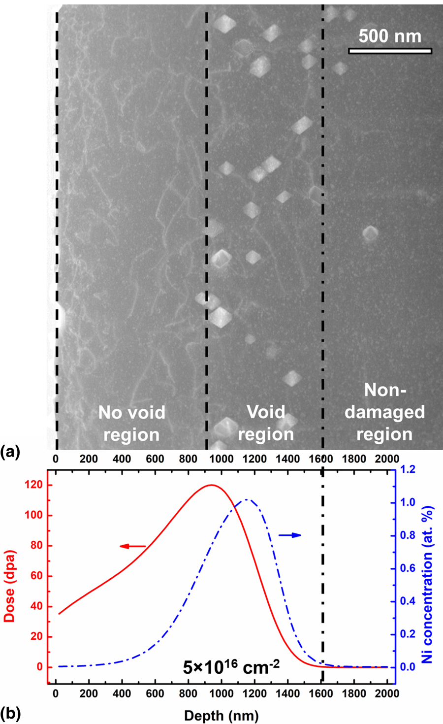
Figure 1(a) shows the void distribution in NiCoFeCr irradiated at 580 °C to 5 × 1016 cm−2. Despite the substantial irradiation damage and the high dislocation density between the free surface to ~900 nm, no voids form in this region, denoted as No Void Region. Most of the voids are located in the region from ~900 to 1600 nm, denoted as Void Region. Beyond 1600 nm, the irradiation damage and injected Ni concentration predicted by SRIM (the stopping and range of ions in matter) calculation are close to 0 [Fig. 1(b)]. In this region, limited dislocations and voids are observed, denoted as Non-damaged Region.
Void distribution in NiCoFeCr irradiated at 580 °C to 5 × 1016 cm−2. (a) Dark-field STEM (scanning transmission electron microscopy) image with a zone axis of [110]. (b) SRIM-predicted damage production profile and injected Ni concentration. Beyond the dash-dot line, SRIM calculation predicts no damage.
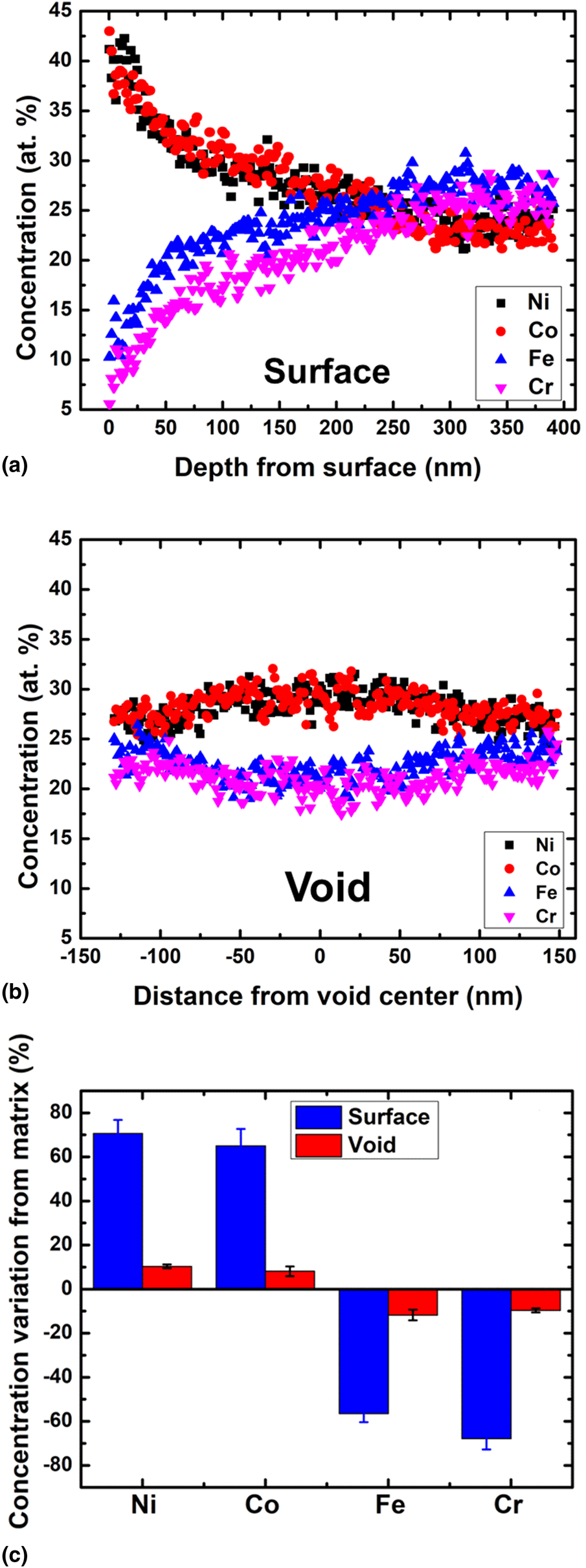
Element segregation around free surface and voids in this sample are shown in Fig. 2. For both defects, Ni/Co is enriched and Fe/Cr is depleted [Figs. 2(a) and 2(b)]. However, the maximum concentration change is much more significant around free surface than voids [Fig. 2(c)]. The concentration change is maximum at the free surface and gradually reaches nominal concentration (25 at.%) at a depth of 222 ± 22 nm, which indicates the width of the surface-affected region. The maximum concentration change for voids occurs around the center of the voids, and the average void size is 86 ± 9 nm (since the voids are highly faceted, void size is calculated as the average length of shorter and longer axes). Segregation around different positions of the free surface and at least 10 voids were measured to ensure statistical significance.
Element segregation around defects in NiCoFeCr irradiated at 580 °C to 5 × 1016 cm−2. (a) Element segregation as a function of depth from the free surface. (b) Element segregation as a function of distance from a void center. (c) Comparison of maximum concentration variation of voids and surfaces with respect to the matrix.
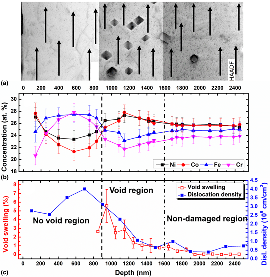
By studying the energy-dispersive X-ray spectroscopy (EDS) line scan profiles at different depths, we investigated the matrix concentration evolution with respect to depth (the width of line scans is ~20 nm, thus we essentially measured the average matrix concentration of a band instead of a line). Arrows in Fig. 3(a) represent the locations of line scans which avoided the nearby regions of voids so that more accurate concentration of the matrix can be obtained. Each data point in Fig. 3(b) corresponds to the average matrix concentration of each EDS line scan in Fig. 3(a). Figures 3(b) and 3(c) show the close correlation between the matrix concentration variation and void distribution. In the No Void Region, the matrix concentration is high in Fe/Cr and low in Ni/Co (except the surface-affected region). In contrast, in the Void Region, the matrix concentration is low in Fe/Cr and high in Ni/Co. The depth where the concentration variation trend reverses (~900 nm) is also the boundary between the No Void Region and Void Region. In the Non-damaged Region, the concentration barely changes, and limited amount of voids and few dislocations exist.
Correlation between matrix concentration and defect distribution in NiCoFeCr irradiated at 580 °C to 5 × 1016 cm−2. (a) HAADF-STEM (high-angle annular dark-field) image with a zone axis of [110]. EDS line scans in the matrix are indicated by the arrows. (b) The evolution of matrix concentration with respect to depth. (c) The evolution of void swelling and dislocation density with respect to depth. The data in (c) are from Ref. [Reference Fan, Yang, Kombaiah, Wang, Edmondson, Osetsky, Jin, Lu, Bei, Wang, More, Weber and Zhang22].

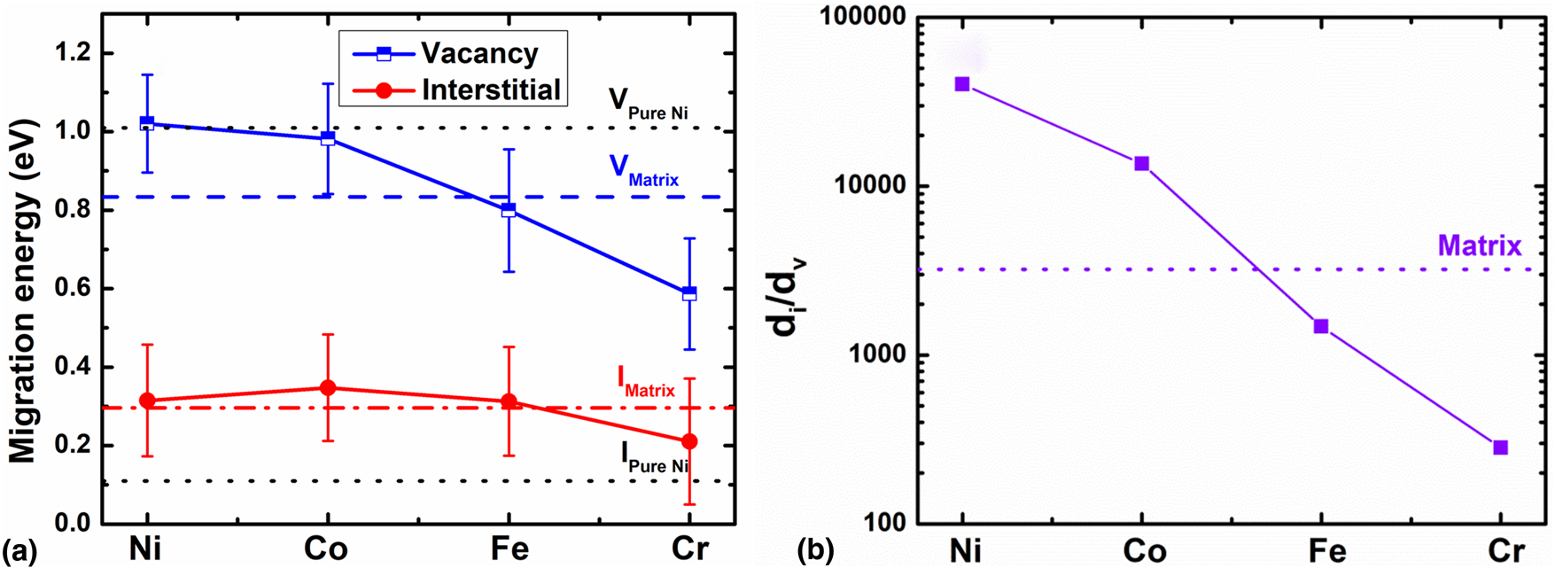
Figure 4(a) demonstrates the preferential diffusion of vacancies and interstitials among the constituent elements in NiCoFeCr. The migration energy of pure Ni is a fixed value as indicated by the dotted lines, and the migration energies of different constituent elements in NiCoFeCr via interstitial and vacancy mechanisms were obtained by averaging at least 30 barriers for each element through first-principles calculation based on the density functional theory as implemented in the Vienna ab initio simulation package (VASP) [Reference Fan, Yang, Kombaiah, Wang, Edmondson, Osetsky, Jin, Lu, Bei, Wang, More, Weber and Zhang22, Reference Zhao, Egami, Stocks and Zhang32, Reference Kresse and Furthmüller33]. Unlike the fixed migration energies in pure Ni, migration energies in NiCoFeCr have a wide distribution for each element indicated by the error bar. Differences between interstitial migration energies via different atoms are relatively small (within 0.14 eV). However, the barrier of the vacancy migration mechanism for vacancy exchange with Fe/Cr is obviously smaller than that with Ni/Co: migration barrier drops from 1.02 to 0.59 eV (from Ni to Cr). This implies that the vacancy mechanism could contribute more significantly into the chemically biased diffusion. Since vacancies preferably exchange with Fe/Cr atoms, the flow of vacancies would lead to the flow of Fe/Cr atoms in the opposite direction. The diffusivity ratio of interstitial over vacancy is shown in Fig. 4(b).
Migration energy and diffusivity ratio among the constituent elements in NiCoFeCr. (a) Average migration energy of vacancy and interstitial calculated by density functional theory calculation [Reference Fan, Yang, Kombaiah, Wang, Edmondson, Osetsky, Jin, Lu, Bei, Wang, More, Weber and Zhang22, Reference Zhao, Egami, Stocks and Zhang32]. The average vacancy and interstitial migration energy for the matrix are indicated by the dashed and dash-dot line, respectively, and the migration energies for pure Ni were also indicated by the dotted lines. (b) The diffusivity ratio of interstitial over vacancy. The dotted line represents the diffusivity ratio of the matrix.
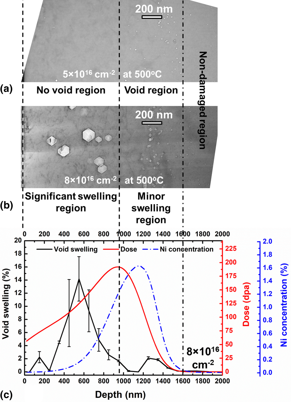
The void distribution as a function of depth in NiCoFeCr irradiated to 5 × 1016 cm−2 at 580 °C (Fig. 3) is similar to that at 500 °C [Fig. 5(a)]: the No Void Region (from the free surface to ~900–1000 nm) contains very few voids, and the Void Region (from ~900–1000 to 1600 nm) contains the majority of the voids. However, the No Void Region in NiCoFeCr irradiated at 500 °C to 5 × 1016 cm−2 turns into the Significant Swelling Region due to the void nucleation and growth in the region when irradiation damage increased to 8 × 1016 cm−2 [Fig. 5(b)]. In the meantime, voids in depth deeper than ~1000 nm (corresponding to the Void Region at 5 × 1016 cm−2) grow slowly up to 8 × 1016 cm−2 (Minor Swelling Region). The evolution of the matrix concentration with respect to depth for NiCoFeCr irradiated to 8 × 1016 cm−2 at 500 °C is shown in Fig. 6. Similar to NiCoFeCr irradiated at 580 °C (Fig. 3), an apparent correlation between matrix concentration and void distribution exists in NiCoFeCr irradiated at 500 °C (Fig. 6). The matrix concentration is high in Fe/Cr and low in Ni/Co in depth shallower than ~1000 nm, which corresponds to the No Void Region at 5 × 1016 cm−2 and the Significant Swelling Region at 8 × 1016 cm−2. The matrix concentration trend reverses from ~1000 to 1600 nm which corresponds to the Void Region at 5 × 1016 cm−2 and the Minor Swelling Region at 8 × 1016 cm−2. In the Non-damaged Region, the concentration profile remains unchanged with limited voids and no dislocations.
Transition from suppressed void formation to substantial void growth with increasing dose in NiCoFeCr irradiated at 500 °C. Bright-field TEM images (under-focused) of NiCoFeCr irradiated to (a) 5 × 1016 cm−2 and (b) 8 × 1016 cm−2. (c) Void swelling, SRIM-predicted damage production profile, and injected Ni concentration as a function of depth for NiCoFeCr irradiated to 8 × 1016 cm−2. Beyond the dash-dot line, SRIM calculation predicts no damage. The void swelling data in (c) are from Ref. [Reference Fan, Yang, Kombaiah, Wang, Edmondson, Osetsky, Jin, Lu, Bei, Wang, More, Weber and Zhang22].
Correlation between matrix concentration and void distribution in NiCoFeCr irradiated at 500 °C to 8 × 1016 cm−2. (a) HAADF-STEM image with a zone axis of [110]. EDS line scans in the matrix are indicated by the arrows. (b) The evolution of matrix concentration with respect to depth. (c) The evolution of void swelling with respect to depth (squares). For comparison, the void evolution in NiCoFeCr irradiated at 500 °C to 5 × 1016 cm−2 is also shown (circles). Note that the scales for two fluences are different. The void swelling data in (c) are from Ref. [Reference Fan, Yang, Kombaiah, Wang, Edmondson, Osetsky, Jin, Lu, Bei, Wang, More, Weber and Zhang22].

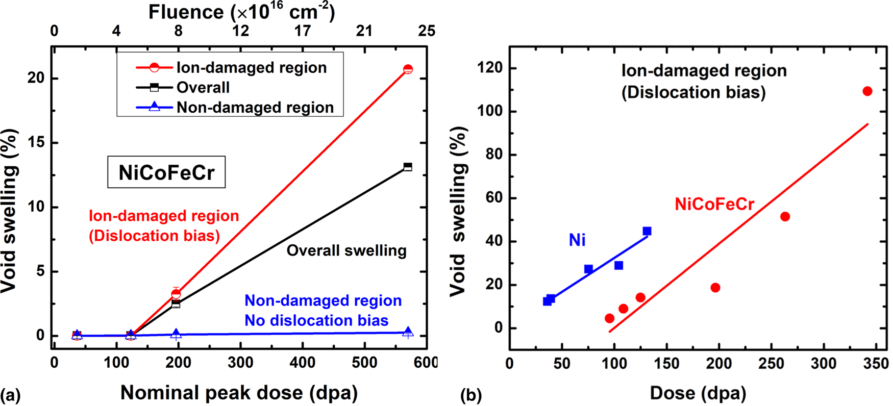
Void swelling as a function of dose is presented in Fig. 7. Figure 7(a) shows the void swelling in different regions as a function of fluence and nominal peak dose (which is the highest dpa calculated from each fluence). For each peak dose, the Ion-damaged Region covers the whole SRIM-predicted damage range where the majority of dislocations exist (from the free surface to ~1600 nm); the Non-damaged Region contains voids but very few dislocations (from ~1600 nm to the deepest depth where voids exist); Overall swelling covers the region from the free surface to the deepest depth where voids exist. Thus, the Ion-damaged Region includes both the No Void Region and Void Region at lower doses, and includes both the Significant Swelling Region and Minor swelling Region at higher doses. With the increase of fluence/nominal peak dose, void swelling in the Non-damaged Region (no dislocation bias) increases negligibly (triangles), void swelling in the Ion-damaged Region (dislocation biased) rises drastically after incubation dose (circles), and the overall swelling increases at a medium rate (squares). To understand the actual void swelling rate, local void swelling at a certain depth with respect to its actual dose at this depth is shown in Fig. 7(b). The depth where void swelling data were acquired in NiCoFeCr lies in the vicinity from 400 to 600 nm where the effects of the free surface and injected interstitials are minimum [Reference Zinkle and Snead34]. These data are only available in the Significant Swelling Region when significant void growth occurs beyond the incubation dose. With these data, the void swelling rate in NiCoFeCr can be obtained. The void swelling rate in NiCoFeCr is very similar to the void swelling rate in pure Ni irradiated under similar conditions [Fig. 7(b)]. It should be noted that the dose rate for NiCoFeCr data ranges from ~3.3 to 10 × 10−3 dpa/s and the dose rate for Ni data ranges from ~4.1 to 7.3 × 10⁻³ dpa/s. As a result, the dose rate difference may affect the swelling rate, but its effect is considered to be insignificant.
Void swelling with respect to dose in NiCoFeCr. (a) The evolution of void swelling in the ion-damaged region, non-damaged region, and overall swelling (including both ion-damaged and non-damaged regions) as a function of nominal peak dose and fluence. (b) The evolution of void swelling as a function of actual dose (circles). For comparison, the evolution of void swelling as a function of actual dose for Ni is also shown (squares).
Discussion
Preferential diffusion associated with segregation around defects
Segregation around various defects in NiCoFeCr-based HEAs has been reported before: Ni/Co is enriched and Fe/Cr is depleted across dislocation loops in both electron-irradiated and ion-irradiated NiCoFeCr [Reference Lu, Yang, Jin, Gao, Xiu, Zhang, Gao, Bei, Weber and Sun28, Reference He, Wang, Shi, Jin, Bei, Yasuda, Matsumura, Higashida and Robertson29] and in ion-irradiated NiCoFeCrAl0.1 [Reference Yang, Xia, Guo, Hu, Poplawsky, Sha, Fang, Yan, Wang and Li17], around voids in ion-irradiated NiCoFeCr [Reference Fan, Yang, Kombaiah, Wang, Edmondson, Osetsky, Jin, Lu, Bei, Wang, More, Weber and Zhang22], and at grain boundaries in ion-irradiated NiCoFeCrMn [Reference Barr, Nathaniel, Unocic, Liu, Zhang, Wang and Taheri30]. This is analogous to the segregation trend of Ni enrichment and Fe/Cr depletion in the classical FeCrNi austenitic steels [Reference Was, Wharry, Frisbie, Wirth, Morgan, Tucker and Allen35, Reference Allen, Busby, Was and Kenik36, Reference Watanabe, Sakaguchi, Hashimoto, Nakamura, Takahashi, Namba and Lam37]. However, in most of these NiCoFeCr-based HEAs, nanostructured defects (such as twin boundaries and precipitates) are absent, thus the segregation of elements mainly results from the preferential diffusion of constituent elements. Figure 4(a) shows the average migration energies of vacancies and interstitials through different elements in NiCoFeCr (The distribution of migration energies can be found in Ref. [Reference Zhao, Egami, Stocks and Zhang32]). The average interstitial migration energy  $\lpar {E_{\rm m}^{\rm i} } \rpar$ is similar for Ni, Co, and Fe (0.313–0.348 eV) and is slightly lower for Cr (0.211 eV). In contrast, the average vacancy migration energy $\lpar {E_{\rm m}^{\rm v} } \rpar$ is similar for Ni (1.021 eV) and Co (0.982 eV), both of which are higher than the average $E_{\rm m}^{\rm v}$ of the matrix. However, $E_{\rm m}^{\rm v}$ is lower for Fe (0.799 eV) and dramatically lower for Cr (0.587 eV) than the matrix. When certain atoms have lower migration barrier to exchange with vacancies and/or certain atoms have a positive binding energy with interstitials, chemically biased diffusion takes place: certain alloying elements diffuse faster than others. This phenomenon was studied by atomistic modeling, and it is demonstrated that it contributes to segregation under irradiation [Reference Zhao, Osetsky and Zhang38, Reference Barashev, Osetsky, Bei, Lu, Wang and Zhang39]. The usual mechanism for vacancy migration is to exchange its position with the neighboring atoms, thus creating an atomic flow opposite to vacancy flow direction. In other words, the particular atom-vacancy transport coefficient is negative [Reference Osetsky, Béland and Stoller40]. On the contrary, the interstitial migration mechanism can be characterized by a positive transport coefficient for certain elements. Segregation via chemically biased diffusion occurs around defect sinks in a way that elements diffusing faster via the vacancy mechanism would be depleted and elements diffusing faster via the interstitial mechanism would be enriched. Besides, high irradiation damage would generate high concentration of interstitials and vacancies (a few orders of magnitude higher than the thermodynamic equilibrium concentration) and their diffusion defines the microstructure evolution including segregation. Thus, an element with a higher interstitial diffusivity (d i) and lower vacancy diffusivity (d v) is more likely to be enriched around defect sinks. For simplicity, if we assume similar migration entropies for interstitials and vacancies, the diffusivity ratio of interstitial over vacancy can be expressed as follows [Reference Was41]:
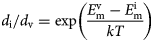 $$d_{\rm i}{\rm /}d_{\rm v} = {\rm exp}\left({\displaystyle{{E_{\rm m}^{\rm v} -E_{\rm m}^{\rm i} } \over {kT}}} \right)$$
where k is Boltzmann's constant and T is the temperature (773 K is used for this study).
As shown in Fig. 4(b), compared with matrix, d i/d v of Ni/Co is above the ratio of the average matrix, while d i/d v of Fe/Cr is below the ratio of the average matrix. This implies that Ni/Co enriches and Fe/Cr depletes around defect sinks in NiCoFeCr. This is the major cause leading to the segregation trend reported in our current study and previous studies. Furthermore, Fig. 2 demonstrates that segregation around free surface is drastically higher than voids, which indicates much stronger sink strength of the free surface. Segregation around voids can affect materials’ bulk properties, such as mechanical strength and fracture behaviors, but segregation around free surface affects both bulk properties and surface properties such as wear and corrosion responses. The effects of surface segregation on the properties of HEAs deserve more attention. Regardless of the amount of segregation, our current and previous studies have confirmed enrichment of Ni/Co and depletion of Fe/Cr around defects at different irradiation depths. Different from the consistent trend of segregation around defect sinks, our results below will show that the concentration variation in the matrix depends on the irradiation depth and is closely tied with the void growth.
Matrix concentration variation and void evolution
A previous work by Fan et al. [Reference Fan, Yang, Kombaiah, Wang, Edmondson, Osetsky, Jin, Lu, Bei, Wang, More, Weber and Zhang22] studied detailed dislocation and void evolution in NiCoFeCr with respect to temperature and dose, and our current work mainly studies the matrix concentration variation associated with preferential diffusion in irradiated NiCoFeCr. As shown below, since matrix concentration variation can play an important role in void swelling, we referred to and discussed some related data from Ref. [Reference Fan, Yang, Kombaiah, Wang, Edmondson, Osetsky, Jin, Lu, Bei, Wang, More, Weber and Zhang22]. The matrix concentration variation in ion-irradiated NiCoFeCr can be divided into four regions:
(i) Ni/Co enrichment and Fe/Cr depletion near free surface (width of the surface-affected region depends on irradiation conditions);
(ii) Ni/Co depletion and Fe/Cr enrichment in the No Void Region at lower doses and the Significant Swelling Region at higher doses (beyond surface-affected region to ~900–1000 nm);
(iii) Ni/Co enrichment and Fe/Cr depletion in the Void Region at lower doses and the Minor Swelling Region at higher doses (from ~900–1000 nm to the end of the irradiated range, 1600 nm);
(iv) Stable concentration with no obvious element segregation (beyond 1600 nm) (Figs. 3 and 6).
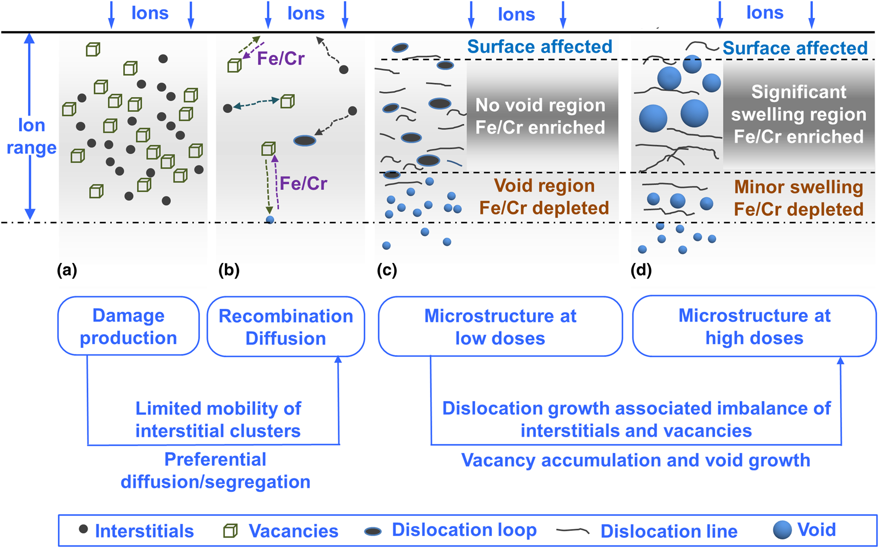
The underlying mechanisms that are responsible for the matrix concentration variation under irradiation come from the chemically biased diffusion. As depicted in Fig. 8, after damage production, due to the limited mobility of interstitial clusters in concentrated alloys and HEAs [Reference Lu, Niu, Chen, Jin, Yang, Xiu, Zhang, Gao, Bei and Shi20, Reference Barashev, Osetsky, Bei, Lu, Wang and Zhang39], a large amount of interstitials and vacancies recombine reducing the radiation damage at the initial stage. However, small interstitial clusters produced directly in displacement cascades could accumulate and grow as dislocation loops or lines in the Ion-damaged Region. Voids are neutral sinks to absorb both interstitials and vacancies creating local enrichment of Ni/Co and depletion of Fe/Cr around voids. This segregation trend prevents further void growth and activates their shrinkage as described in Ref. [Reference Barashev, Osetsky, Bei, Lu, Wang and Zhang39]. The same mechanism creates similar segregation around interstitial-type defects (Ni/Co enrichment and Fe/Cr depletion around dislocations) that enhances their stability and growth. Thus, chemically biased diffusion creates conditions that suppresses void formation and enhances the growth of interstitial-type defects via segregation bias. As a result, the No void Region is formed at lower doses where the depth is shallower than ~900–1000 nm, and in this region, dislocation density is high.
Schematic of defect evolution and matrix concentration variation in ion-irradiated NiCoFeCr at elevated temperatures. (a) Production of interstitials and vacancies upon radiation. (b) Defect recombination and diffusion. (i) Enhanced interstitial-vacancy recombination in the peak damage region due to limited mobility of interstitials, (ii) preferential diffusion of vacancies outside of the peak damage region through Fe/Cr, and (iii) formation and growth of dislocations due to the accumulation of interstitials mainly in the peak damage region. (c) Microstructure at low doses. Due to preferential diffusion, dislocations dominate and no voids exist in the peak damage region where Fe/Cr is enriched and small voids form at the end of the ion-damaged region where Fe/Cr is depleted. (d) Microstructure at high doses. As the dislocations and matrix concentration evolve, voids are nucleated and grow substantially in the peak damage region. Details regarding the transition from suppressed void formation (c) to significant void swelling (d) can be found in Ref. [Reference Fan, Yang, Kombaiah, Wang, Edmondson, Osetsky, Jin, Lu, Bei, Wang, More, Weber and Zhang22].
Since void formation is currently suppressed in this region, and it has been shown that at 500 °C or higher temperatures vacancy clusters may not be stable in NiCoFeCr [Reference Fan, Velisa, Jin, Crespillo, Bei, Weber and Zhang42, Reference Zinkle43], the significant amount of vacancies generated in the No Void Region could either be annihilated by interstitials or escape from the region. The concurrent emergence of voids at the end of and especially beyond the ion-damaged region (Void Region and Non-damaged Region) suggests that vacancies in the No Void Region can diffuse into deeper regions where vacancy concentration is lower. As Ni/Co is enriched around dislocations in the No Void Region, locally Fe/Cr enriched “channels” can form between dislocations. Since vacancy migration in NiCoFeCr favors Fe/Cr, vacancy can migrate out of the region through these “channels” where vacancy mobility is higher. The transport of vacancies from the No Void Region to Void Region would lead to the opposite flow of Fe/Cr. Therefore, the matrix concentration of Fe/Cr is higher in the No Void Region and lower in the Void Region, and a clear matrix concentration crossover occurs at ~900–1000 nm beyond which voids form at lower doses (Figs. 3 and 6). The preferential diffusion of vacancies in NiCoFeCr not only leads to suppressed void formation in the No Void Region and void formation in the Void Region and Non-damaged Region but also significantly decreases the overall void swelling. In the Void Region and Non-damaged Region, lower concentration of interstitials allows voids to grow, but leads to slow growth rate of voids due to the lack of strong dislocation bias and a neutral character of voids as interstitial and vacancy sinks [Fig. 3(c)]. Thus, the preferential diffusion in NiCoFeCr essentially creates an incubation period where voids do form at deeper depth but grow with a lower rate.
After incubation period, voids can nucleate in the No Void Region at lower doses and grow with a higher rate, which transforms the No Void Region at low doses into the Significant Swelling Region at higher doses (Fig. 5). This transition could be a result of the growth of dislocation networks at higher doses. As shown in Ref. [Reference Fan, Yang, Kombaiah, Wang, Edmondson, Osetsky, Jin, Lu, Bei, Wang, More, Weber and Zhang22], individual dislocation loops develop into extended dislocation networks with increasing dose, and the conventional dislocation bias increases and may exceed the segregation bias effect. Vacancy supersaturation increases and encourages void nucleation and growth in the initial No Void Region. After the transition from suppressed to significant void growth occurs from lower to higher doses, the matrix concentration variation does not change significantly (Fig. 6). This is because now vacancies flow to voids inside of the region (in depths shallower than ~900–1000 nm), and their transport into deeper regions reduces significantly, therefore reducing the opposite flow of Fe/Cr. Thus, the microstructure evolution is associated with not only local segregation around defect sinks but also with larger-scale redistribution of elements in the matrix. Both the local segregation and matrix concentration variation are expected to be significant at high temperatures and/or irradiation doses, which could lead to physical, chemical, and mechanical properties changes at different scales and should be taken into consideration while considering HEAs as structural materials for various applications.
It should be noted that the peak concentration of implanted Ni ions can reach ~1 at.% (with a fluence of 5 × 1016 cm−2) and ~1.6 at.% (8 × 1016 cm−2). Such high concentration of injected Ni atoms is expected to affect void formation. Yang et al. [Reference Yang, Lu, Jin, Crespillo, Zhang, Bei and Wang21] studied a series of ion-irradiated Ni-based concentrated alloys and found that the effect of injected interstitials on void suppression is more pronounced in Ni and NiCo than NiCoFeCr. In Fig. 5(b), a clear void-denuded zone in NiCoFeCr irradiated to 8 × 1016 cm−2 at 500 °C exists from ~1000 to 1200 nm (slightly ahead of the peak concentration of injected Ni atoms), which should be a result of void suppression due to high concentration of injected interstitials.
Overall microstructural and chemical evolution and its implications
At lower doses, the matrix concentration variation is developed and leads to the unusual void distribution. At higher doses, matrix concentration variation does not change too much, and microstructure evolution in NiCoFeCr is analogous to pure metals and conventional alloys (Fig. 8). The preferential diffusion-mediated matrix chemical variation and unusual void distribution correspond to the incubation period for void swelling at lower doses, and after incubation void growth in different regions varies significantly [Fig. 7(a)]. Voids in the Non-damaged Region continue to grow with a low rate similar to the rate in the incubation period, but voids in the Ion-damaged Region grow rapidly and dominate the overall void swelling at higher doses. At lower doses, the main mechanisms that operate and compete include dislocation and segregation biases. With the increase of nominal peak dose, dislocation bias in the Ion-damaged Region causes more interstitials flow to dislocations, and thus, more vacancies are left for void nucleation and growth. At doses higher than the incubation dose, the No Void Region at low doses would convert into the Significant Swelling Region at higher doses, and the void swelling rate in NiCoFeCr is similar to pure Ni [Fig. 7(b)]. The calculated void swelling rate is ~0.8 ± 0.17%/dpa (SRIM quick mode is used to be consistent with the literature), very close to the classical void swelling rate of face-centered cubic alloys (1%/dpa) [Reference Garner44, Reference Garner45] controlled mainly by the conventional dislocation bias. In other words, void swelling in HEAs at higher doses may not differ too much from conventional alloys. The similar swelling rates at higher doses suggest that the key mechanism to suppress void swelling in HEAs is extending the incubation period (increasing the incubation dose). The incubation dose is associated with the formation of extended dislocation networks, and the significant local and global chemical composition changes. Further increasing the incubation dose can be achieved by controlling defect mobility and diffusion, such as dramatically decreasing mobility of both interstitials and vacancies to enhance their local recombination and inhibiting their long-range diffusion toward sinks. The defect mobility and diffusion behaviors in concentrated alloys and HEAs can be changed by tailoring their chemical composition and concentration [Reference Zhao, Osetsky and Zhang38, Reference Vaidya, Pradeep, Murty, Wilde and Divinski46, Reference Fan, Zhao, Jin, Chen, Osetskiy, Wang, Bei, More and Zhang47, Reference Wang, Liu and Dou48, Reference Tong, Velisa, Zhao, Guo, Yang, Jin, Lu, Bei, Ko, Pagan, Zhang, Wang and Zhang49]. Our results suggest that the optimal diffusion may be achieved by selecting elements with suitable diffusivities and tuning their concentrations (Fig. 4). This can potentially guide the design of HEAs deviating from near-equimolar ratios. Osetsky et al. [Reference Osetsky, Barashev, Béland, Yao, Ferasat and Zhang50] have recently discussed how to enhance diffusion percolation effects in concentrated alloys.
It should be mentioned that HEAs for practical nuclear or other applications are less likely to be single crystalline. Generally, sophisticated nanostructures are introduced into HEAs to improve their properties. These nanostructures such as grain boundaries, phase boundaries, or twin boundaries could effectively absorb or trap defects and relieve radiation damage [Reference Misra, Demkowicz, Zhang and Hoagland51, Reference Fan, Fan, Li, Shang, Xue, Kirk, Li, Wang and Zhang52, Reference Beyerlein, Caro, Demkowicz, Mara, Misra and Uberuaga53, Reference Fan, Li, Fan, Wang and Zhang54, Reference El-Atwani, Hinks, Greaves, Allain and Maloy55], but could also change the preferential diffusion in HEAs at the same time. Thus, whether matrix concentration variation and the unusual void evolution can happen in nanostructured HEAs requires more research. It should also be noted that our study mainly considers the average migration energy and its effect on preferential diffusion. However, the migration energy for each element can have a wide distribution in HEAs in contrast to a fixed value of migration energy for pure metals. It is not clear that how the energy distribution would affect preferential diffusion and evolve with the microstructural evolution. Moreover, recent studies have shown effects of local chemical variation (in the form of short-range order or composition fluctuation) on materials’ conductivity and mechanical behavior [Reference Li, Sheng and Ma23, Reference Zhang, Zhao, Jin, Xue, Velisa, Bei, Huang, Ko, Pagan and Neuefeind24, Reference Ding, Zhang, Chen, Fu, Chen, Chen, Gu, Wei, Bei, Gao, Wen, Li, Zhang, Zhu, Ritchie and Yu25]. The substantial matrix chemical variation due to radiation is expected to seriously tailor a variety of materials properties and worthy of future explorations.
Conclusions
In this work, we studied the preferential diffusion-mediated concentration variation and void evolution in Ni-ion-irradiated NiCoFeCr HEA. Preferential diffusion not only leads to enrichment of Ni/Co and depletion of Fe/Cr around defects but also results in larger-scale matrix concentration variation with respect to depth. Due to the preferential diffusion of vacancies through Fe/Cr, vacancies can escape from the shallow region (smaller than a depth of ~900–1000 nm) where very few voids form at lower doses, and more Fe/Cr exists in the matrix of this region. Escaped vacancies can migrate and form voids in deeper region, but the void growth rate is low and more Ni/Co exists in the matrix of the region. At higher doses, voids eventually form in the shallow region and leads to significant swelling with a high growth rate comparable to pure Ni. This study demonstrates the substantial chemical concentration variation in irradiated HEA and its direct impact on void evolution. The matrix concentration variation as a function of depth should highly depend on the irradiation conditions and materials properties. Irradiation-induced chemical concentration variation deserves more in-depth investigations to fulfill the potential of HEAs as robust nuclear structural materials.
Experimental
Single crystals were grown in an optical floating zone furnace from polycrystalline ingots through the directional solidification method [Reference Bei and George56]. Ingots were prepared by mixing an arc-melting equal amount of elemental Ni, Co, Fe, and Cr (>99.9% purity) and then re-melted five times to ensure homogeneity before drop casting into a copper mold. The alloy was irradiated with 3 MeV Ni2+ ions to 5 × 1016 cm−2 (~123 dpa) and 8 × 1016 cm−2 (~196 dpa) at 500 °C and to 5 × 1016 cm−2 at 580 °C at the Ion Beam Materials Lab (IBML) at the University of Tennessee [Reference Zhang, Crespillo, Xue, Jin, Chen, Fontana, Graham and Weber57]. The flux for all the irradiations is ~2.8 × 10¹² ions/cm2/s. The defocused ion beam was wobbled in the horizontal and vertical directions at a frequency of 517 × 64 Hz to ensure uniform irradiation. The damage profile and injected ion concentration were calculated using SRIM-2008 full cascade mode since NiCoFeCr contains multiple principal-elements rather than single-element metals (It should be noted that many of the previous studies used SRIM quick mode, and the calculated dpa value from full cascade mode is roughly ~2.3 times as high as the value obtained from quick mode) [Reference Weber and Zhang58]. The displacement threshold energy for all the elements is assumed as 40 eV [Reference Ziegler, Ziegler and Biersack59]. The density of NiCoFeCr used for SRIM is 8.144 g/cm3 [Reference Fan, Yang, Kombaiah, Wang, Edmondson, Osetsky, Jin, Lu, Bei, Wang, More, Weber and Zhang22].
The focused ion beam (FIB) lift-out technique was used for cross-section transmission electron microscopy (TEM) sample preparation on an FEI Nova 200 Dual-Beam scanning electron microscopy (SEM)/FIB (Thermo Fisher Scientific, Hillsboro, OR). TEM specimens were prepared by trenching and initial thinning with 30 keV Ga ions and then polished with gradually reduced ion energy down to 2 keV to remove the majority of ion-induced damage. EDS chemical mapping was conducted using an FEI Talos 200X TEM/STEM with ChemiSTEM operated at 200 keV. The compositional profiles are quantified element concentration in atomic percentage from Quantity maps (Q-maps) which were calculated by using the Espirit-Bruker software and applying the Cliff–Lorimer method on the EDS X-Ray count maps [Reference Lorimer60]. In this method, the bremsstrahlung background was subtracted from the X-ray signal for accurate quantification. No binning of pixels was applied in the Q-map calculation. Microstructure characterization after irradiation was performed by FEI Titan S aberration-corrected TEM-STEM operated at 300 keV. Details regarding void swelling calculations can be found in Refs. [Reference Yang, Lu, Jin, Crespillo, Zhang, Bei and Wang21, Reference Fan, Yang, Kombaiah, Wang, Edmondson, Osetsky, Jin, Lu, Bei, Wang, More, Weber and Zhang22].
Acknowledgments
This work is supported as part of the Energy Dissipation to Defect Evolution (EDDE), an Energy Frontier Research Center funded by the U.S. Department of Energy, Office of Science, Basic Energy Sciences under contract number DE-AC05-00OR22725. Electron microscopy analyses were performed as part of a user proposal at ORNL's Center for Nanophase Materials Sciences (CNMS), a U.S. DOE Office of Science User Facility. STEM-EDS analyses on FEI Talos F200X S/TEM were supported by the Department of Energy, Office of Nuclear Energy, Fuel Cycle R&D Program, and the Nuclear Science User Facilities.


 Open access