





1 Introduction
Mid-infrared (mid-IR) coherent sources in the region of 3–5 μm are highly demanded in various applications, such as atmospheric communications, gas detection and military photoelectric countermeasures, due to their unique wavelength characteristics[ Reference Wang, Feng, Adamu, Dasa, Antonio-Lopez, Amezcua-Correa and Markos1– Reference Walsh, Lee and Barnes3]. Nowadays, optically pumped gas-filled hollow-core fiber (HCF) lasers have emerged as a promising technique that combines the advantages of conventional gas lasers and silica-based HCFs. These systems exhibit unique merits in the mid-IR region, including rich emission spectra, high output power and excellent beam quality. Gas-filled HCF lasers currently generate mid-IR emission through four principal mechanisms: population inversion[ Reference Jones, Nampoothiri, Ratanavis, Fiedler, Wheeler, Couny, Kadel, Benabid, Washburn, Corwin and Rudolph4, Reference Hassan, Yu, Wadsworth and Knight5], stimulated Raman scattering[ Reference Astapovich, Gladyshev, Khudyakov, Kosolapov, Likhachev and Bufetov6, Reference Wang, Hong, Zhang, Wahlen, Antonio-Lopez, Dasa, Adamu, Amezcua-Correa and Markos7], dispersive waves[ Reference Deng, Gavara, Hassan, Xiong, Hasan and Chang8, Reference Köttig, Novoa, Tani, Günendi, Cassataro, Travers and Russell9] and supercontinuum generation[ Reference Adamu, Habib, Petersen, Lopez, Zhou, Schülzgen, Bache, Amezcua-Correa, Bang and Markos10, Reference Gladyshev, Dubrovskii, Kosolapov, Morozov, Boltalin and Bufetov11]. Among these approaches, the population inversion scheme possesses distinct advantages for achieving high-power mid-IR lasers, owing to its relatively lower threshold requirement. Many demonstrations of mid-IR laser emission have been made in the last decade using various molecular gases, including acetylene (C2H2)[ Reference Song, Zhang, Zhang, Hou and Wang12, Reference Song, Zhang, Zhang, Hou and Wang13], hydrogen bromide (HBr)[ Reference Zhou, Cui, Huang, Li, Wang, Gao, Wang and Wang14, Reference Zhou, Wang, Huang, Cui, Li, Wang, Xi, Gao and Wang15], carbon dioxide (CO2)[ Reference Cui, Huang, Wang, Wang, Zhou, Li, Gao, Wang and Wang16, Reference Wang, Cui, Huang and Zhou17], nitrous oxide (N2O)[ Reference Aghbolagh, Nampoothiri, Debord, Gerome, Vincetti, Benabid and Rudolph18], carbon monoxide (CO)[ Reference Li, Yang, Zhou, Li, Li, Pei, Huang, Shi, Lei, Wang and Wang19], hydrogen cyanide (HCN)[ Reference Nampoothiri, Ratanavis, Campbell and Rudolph20], etc. The CO2 molecule possess a large emission cross-section in the 4–5 μm wavelength range, along with stable physicochemical properties, non-toxicity and harmlessness, making it a potential medium for achieving high-power lasers[ Reference Nampoothiri, Jones, Fourcade-Dutin, Mao, Dadashzadeh, Baumgart, Wang, Alharbi, Bradley, Campbell, Benabid, Washburn, Corwin and Rudolph21]. In 2019, Cui et al. [ Reference Cui, Huang, Wang, Wang, Zhou, Li, Gao, Wang and Wang16] reported the first 4.3 μm continuous-wave (CW) laser emission with 82 mW output power based on CO2-filled hollow-core anti-resonant fiber (HC-ARF), which is pumped by a 2 μm single-frequency CW laser source. Subsequently, through scaling pump power and adopting an amplifier configuration, they successfully improved the output power to 1.1 W[ Reference Wang, Cui, Huang and Zhou17]. Subsequently, Shi et al. [ Reference Shi, Li, Pei, Lei, Lv, Zhou and Wang22] presented the first 4.3 μm nanosecond pulse laser by pumping CO2-filled HCF with a 2 μm nanosecond pulse laser, although the achieved output power was limited to 297 mW. In 2024, by employing a large-mode-area nested HC-ARF as a gas cell to enhance the coupling efficiency and power handling of a high-power pump laser, we demonstrated a 6.6 W CW laser at 4.3 μm under pumping by a hundred-watt-level single-frequency laser at 2 μm[ Reference Song, Yao, Zhang, Zhang, Hou, Wu and Wang23].
However, further enhancing the power level of 4.3 μm CO2-filled HCF laser sources has some ongoing challenges. For population-inversion-based gas-filled HCF laser sources, the filled gas molecule usually operates under the low-pressure condition (within 1–10 mbar). However, the absorption linewidth of CO2 molecules is only in the range of a few hundred MHz under low pressure, which is highly demanded to the spectral bandwidth of high-power pump lasers. In addition, the beam quality of the pump source generally degrades as the power increases. In this case, the mode acceptance capability of the HCF determines the coupling efficiency of the high-power pump laser. A lower coupling efficiency not only limits the output power of the mid-IR laser source but also causes significant heat accumulation at the input end of the HCF. Furthermore, the material absorption loss of silica-based HCFs increases significantly in the 4–5 μm wavelength range, resulting in higher transmission losses in the mid-infrared band, which adversely affects the improvement of mid-IR light source conversion efficiency. Finally, CO2 molecules are also confronted with difficulties with the gain saturation and severe self-absorption under high-power pumping conditions[ Reference Wang, Cui, Huang and Zhou17]. Therefore, it is appealing to develop high-power pump laser source and large-mode-area low-loss HCFs, and suppress the gain saturation and self-absorption of CO2 gas for generating high-power mid-IR lasers.
In this work, we achieve, for the first time, a 10-W-level, 4.3 μm nanosecond pulse laser source in a CO2-filled HC-ARF, by optimizing the pump laser power and HC-ARF performance, and implementing an off-absorption-peak pumping scheme. The pump source is a self-developed single-frequency fiber laser operating in the 2 μm band, with an average power of 125 W, a repetition rate of 10 MHz and a pulse width of 37 ns. A 6.8-m-long eight-tube nested HC-ARF is employed as the gas cell, in which the core diameter reaches up to 150 μm, supporting multiple modes with low-loss transmission at the pump wavelength. The relaxation of the pump beam quality requirement makes it easier to access the high coupling efficiency of the pump laser. As a result, the hundred-watt-level pump laser is coupled into the HC-ARF with an efficiency exceeding 90%, which effectively mitigates heat accumulation at the HC-ARF input end. Meanwhile, the larger core diameter of the HC-ARF increases the capacity for gas molecules, thereby reducing the CO2 pressure requirement under high-power pumping and mitigating collision-induced losses and self-absorption. When the CO2 pressure is optimized to 5.2 mbar, a maximum output power of 10.23 W is achieved at 4.3 μm, with a repetition rate of 10 MHz and a pulse width of 29 ns. A key finding is that this maximum power is only achievable by detuning the pump wavelength from the absorption peak to suppress gain saturation, which correspondingly improved the slope efficiency and output power by 2.52% and 11.75%, respectively, compared to on-absorption-peak pumping. It is the highest power achieved to date in the 4.3 μm region from a CO2-filled HCF laser source. Looking forward, this work paves a new way for high-power mid-IR gas-filled HCF laser sources.
2 Experimental setup
2.1 High-power nanosecond pulse single-frequency fiber laser at 2 μm
Figure 1 presents a schematic diagram of the pump source for the CO2-filled nested HC-ARF laser, which is a self-developed, hundred-watt-level, single-frequency 2 μm nanosecond pulse fiber laser. The pump source comprises a single-frequency nanosecond pulse fiber seed laser followed by multiple stages of fiber amplifiers. Further, the nanosecond pulse seed source is constructed from a distributed feedback (DFB) single-frequency laser diode (DFB; Eblana Photonics EP2000, 2000.6 nm, 2 mW, 2 MHz), a one-stage thulium-doped fiber amplifier (TDFA) and an acousto-optic modulator (AOM). The central wavelength can be accurately tuned from 1999.5 to 2001.6 nm with a precision of 1 pm, covering the R(26)–R(34) absorption lines of the CO2 molecule. The 2 μm CW signal laser is amplified to 500 mW and then modulated by an AOM into nanosecond pulses with a repetition rate of 10 MHz, a pulse width of 37 ns and an average power of 50 mW. Subsequently, the nanosecond pulse laser is boosted to 5.4 W by two stages of thulium-doped fiber pre-amplifiers. The lengths of the gain fiber (Nufern, PM-TDF-10P/130-HE) used in these two pre-amplifiers are 2.6 and 3.5 m, respectively. To further increase the power level of the nanosecond pulsed laser and suppress stimulated Brillouin scattering (SBS) during the power scaling process, the main amplifier employs a 3-m-long large-mode-area thulium-doped fiber (LMA-TDF; Changjin Photonics, CJTDF-25/250) as the gain medium. To optimize beam quality in the main amplifier, the gain fiber is coiled to a diameter of less than 20 cm, selectively enhancing the transmission loss of higher-order modes. Subsequently, a fiber cladding power stripper (CPS) is spliced to the LMA-TDF to remove residual pump and signal light from the cladding. Finally, the output end of the CPS is angled at 8 degrees to suppress Fresnel reflections.
Schematic of the high-power nanosecond pulse single-frequency fiber laser at 2 μm. ISO, isolator; PM-TDF, polarization-maintaining thulium-doped fiber; AOM, acousto-optic modulator; CLS, cladding light stripper; LMA, large mode area; CPS, cladding power stripper.

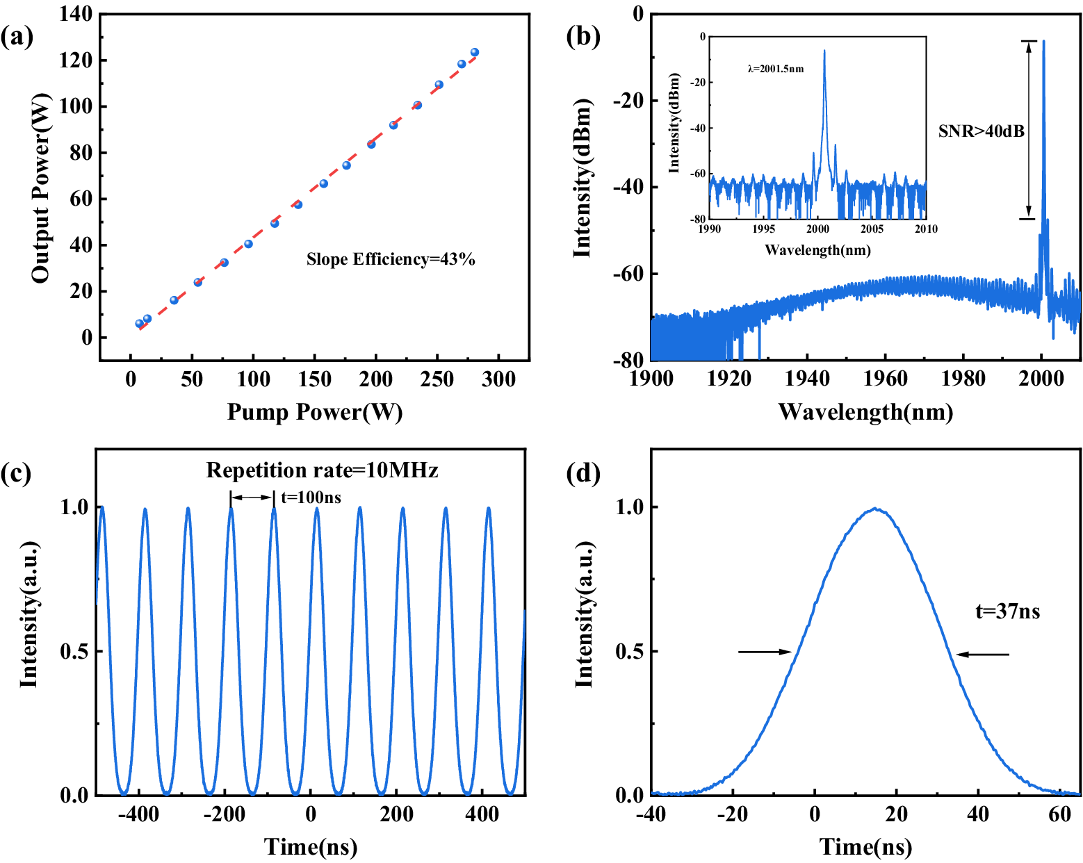
Figure 2 presents the performance of the main amplifier. As shown in Figure 2(a), the 2 μm nanosecond pulse laser power increases linearly with the pump power, which achieves 125 W of maximum power under a pump power of 280 W, with a corresponding slope efficiency of 43%. It can be seen that no significant saturation behavior is observed for 2 μm nanosecond pulse laser power. Hence, further scaling of the output power is limited by the available pump power. Figure 2(b) displays the spectrum of the main amplifier at an output power of 125 W, measured by a near-infrared optical spectrum analyzer (Yokogawa, AQ6375E, 1200–2400 nm, 0.05 nm). Within the 1900–2010 nm range, the signal-to-noise ratio between the single-frequency signal and its adjacent sidebands exceeds 40 dB, while the signal-to-noise ratio relative to the amplified spontaneous emission noise is greater than 50 dB, indicating effective amplification of the single-frequency nanosecond laser signal. No SBS signal is observed in the inset of Figure 2(b), which displays the spectrum from 1990 to 2010 nm, other than the inherent sidebands of the single-frequency laser. This demonstrates the absence of significant nonlinear effects during the amplification process. The temporal characteristics of the 2 μm nanosecond pulse signal at an output power of 125 W are measured using a near-infrared photodetector (Newport, 818-BB-51F) and an oscilloscope (Agilent Technologies, DSO-X 92504A, 25 GHz), as shown in Figures 2(c) and 2(d). In Figure 2(c), the time interval between adjacent pulses is 100 ns, which corresponds to the repetition rate set by the AOM. The absence of significant intensity fluctuations in the pulse train indicates that the amplified pulses maintain high stability. Furthermore, there no noticeable pulse distortion was observed to occur during the amplification process. The pulse width is approximately 37 ns (as shown in Figure 2(d)), corresponding to a peak power of 337 W.
(a) Slope efficiency of the main amplifier. (b) Output spectrum of the main amplifier at 125 W output power. Inset: zoomed-in spectrum. (c) Pulse train. (d) Single pulse profile.

2.2 Large-mode-area nested HC-ARF
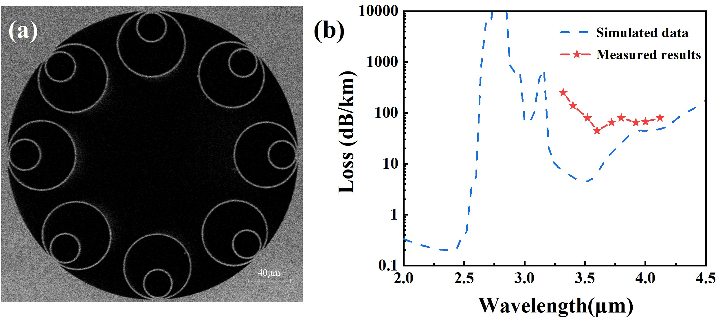
A 6.8-m-long nested HC-ARF is employed as a gas cell in this system; scanning electron microscope photographs are shown in Figure 3(a). It comprises eight silica tubular cladding elements with a core diameter of 150 μm, and the average spacing between the nested tubes is 16.1 μm. The average diameters of the outer and inner tubes are 62.32 and 25.66 μm, respectively, with average tube thicknesses of 1.31 and 1.5 μm. Due to the similar thickness of the inner and outer nested tubes, the HC-ARF is capable of guiding light simultaneously in the 2 and 4.3 μm bands. Moreover, the nested design reduces the confinement loss, and the eight-tube structure increases the capacity for higher-order modes. The large core diameter of the HC-ARF reduces the overlap between the laser field and the silica cladding, thereby decreasing the absorption loss in the 4–5 μm wavelength range. On the other hand, it increases the core-to-wavelength ratio at the 2 μm wavelength, which further improves the fiber’s ability to support higher-order modes.
(a) SEM image of the fabricated eight-tube nested HC-ARF. (b) Transmission loss of large-mode-area nested HC-ARF. Simulated results, blue dashed line; measured results, red dashed line.

The theoretical transmission loss of the fundamental mode over the 2.0–4.5 μm range is shown by the blue dashed line in Figure 3(b), which is calculated using COMSOL Multiphysics simulation software based on the scanning electron microscopy (SEM) image of the HC-ARF. The results indicate that the theoretical transmission losses of the HC-ARF are 68 dB/km@2.0 μm, 99 dB/km@4.3 μm and 125 dB/km@4.4 μm. In addition, the transmission loss of the HCF in the 3.3–4.1 μm band is measured using the cut-back method, with a homemade optical parametric generator (OPG) serving as the test source. The tested fiber was loosely looped during the measurement with a bending diameter of 80 cm to avoid any concerns about bending loss and tension. Figure 3(b) plots the measured transmission loss curve (red dotted line), which is obtained by cutting back the HC-ARF from 24 to 12 m. Over the 3.3–3.6 μm range, the measured transmission loss of the HC-ARF decreases from 0.25 dB/m to approximately 0.05 dB/m. In the 3.6–4.1 μm band, the measured loss fluctuates between 0.05 and 0.08 dB/m. The trend of the measured loss is consistent with the theoretical simulation results. However, due to the relatively short HC-ARF length used in the loss measurement, the influence of higher-order modes and power fluctuations during the measurement process is significant, leading to certain deviations between the measured results and the theoretical simulations.
2.3 Experimental setup of the CO2-filled HC-ARF nanosecond pulse laser source
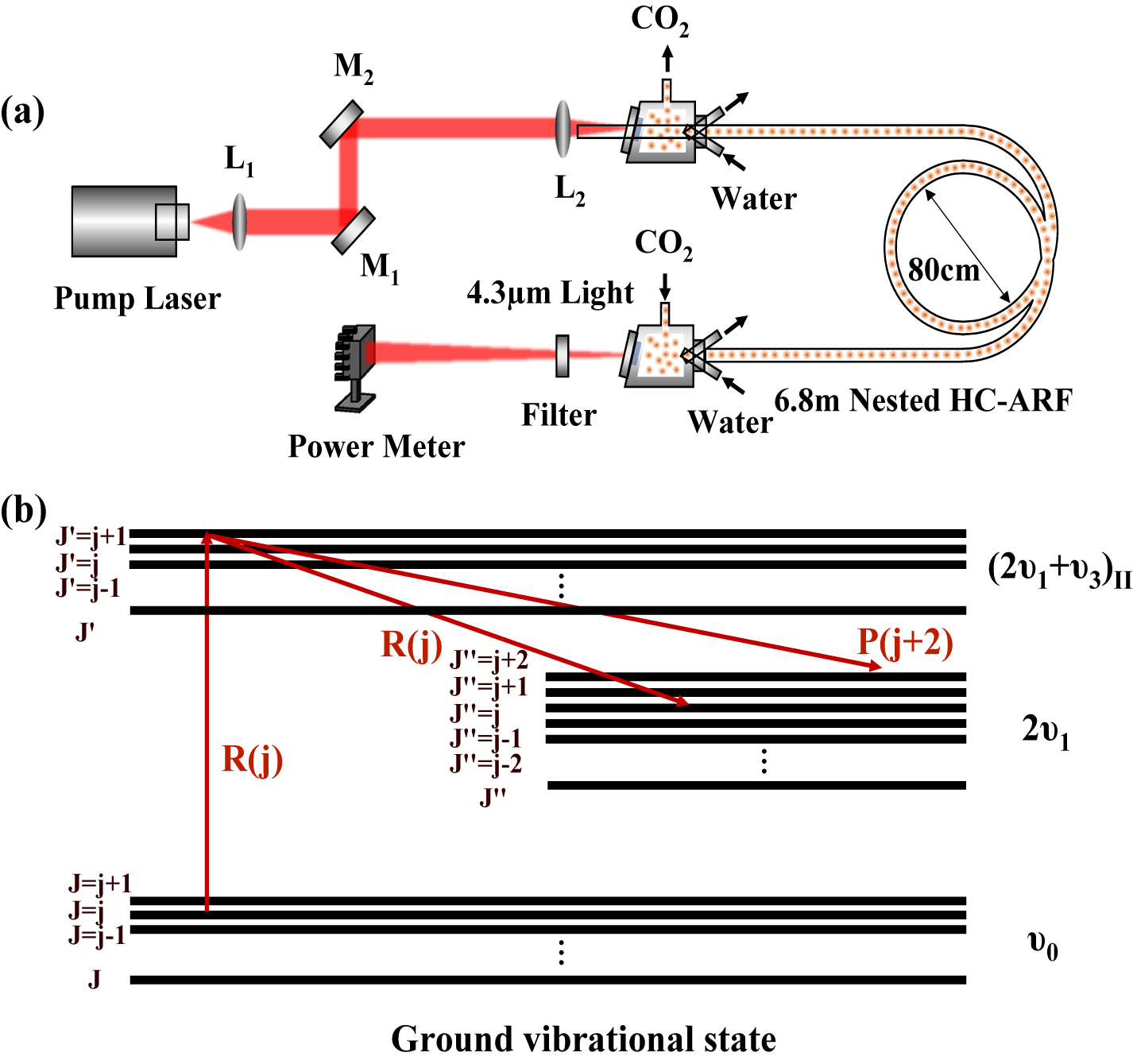
The experimental layout of the CO2-filled HC-ARF nanosecond pulse laser source is illustrated in Figure 4(a). The pump laser passes through a pair of plano-convex lenses (L1 and L2) and two planar dielectric mirrors (M1 and M2: high reflection > 95%@1908–2000 nm), and then couples into the HC-ARF with a coupling efficiency of more than 90%. The 6.8 m length of the nested HC-ARF was also loosely coiled with a bending diameter of 80 cm on the optical table. Both ends of the HC-ARF are sealed in a gas chamber, which features windows at the input and output ports, where the input window is an anti-reflection coated window for the 2 μm band (transmission >98% in the 1.9–2.1 μm range) and the output window is an uncoated calcium fluoride window (transmission >92% in the 1–5 μm range). This specialized design of the gas chamber suppresses back-reflections and withstands high-power laser pumping. At the output end, a mid-IR bandpass filter (Thorlabs FB4250-500) is used to transmit the 4.3 μm signal light (~80% transmission at 4–4.5 μm) while effectively rejecting the pump laser (<0.1% transmission at 2 μm).
(a) Experimental setup of the CO2-filled HC-ARF nanosecond pulse laser source. (b) Simplified energy level of CO2 gas and its transition process.

Figure 4(b) shows the simplified energy levels of CO2 and the corresponding transition process involving the ground vibrational state (ν0), the (2ν1+ν3)II state and the 2ν1 state. Upon excitation of the R(j) absorption line, CO2 molecules transition from the J = j rotational level of the ground vibrational state (ν0) to the J’ = j + 1 rotational level of the (2ν1+ν3)II vibrational state. According to the selection rule ΔJ = ±1[ 24], the two mid-IR emission lines R(j) and P(j+2) are generated. Since the central wavelength of the pump laser covers the R(26)–R(34) absorption lines of CO2 molecules, the CO2-filled HC-ARF laser source has 10 emission lines in the 4 μm band, ranging from 4292 to 4396 nm. They are R(26) at 4300.29 nm, R(28) at 4298.05 nm, R(30) at 4295.86 nm, R(32) at 4293.72 nm, R(34) at 4291.62 nm, P(28) at 4380.97 nm, P(30) at 4384.63 nm, P(32) at 4388.33 nm, P(34) at 4392.08 nm and P(36) at 4395.89 nm.
3 Results and discussion
3.1 Output power characteristics of the mid-IR laser source
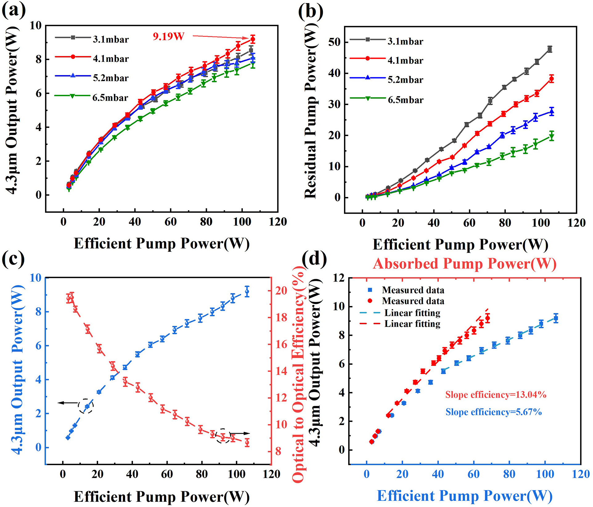
Among the numerous absorption lines covered by the pump laser, the R(26) absorption line and its corresponding two emission lines exhibit relatively large absorption and emission cross-sections[24]. Therefore, selecting the R(26) absorption line for pumping holds the potential for achieving high-power output. Figures 5(a) and 5(b) illustrate the 4.3 μm signal power and 2 μm residual pump power with effective pump power under different CO2 pressures. The signal laser power comprised the total power of the R(26) and P(28) emission lines, which accounts for the inherent transmission losses of the filter and the output window of the gas chamber. The effective pump power is expressed as the output power of the pump laser passing through the nested HC-ARF. When the CO2 pressure increases from 3.1 to 6.5 mbar, the 4.3 μm signal power exhibits a trend of first increasing and then decreasing under the maximum pump power, reaching a maximum value of 9.19 W at 4.1 mbar. In contrast, the corresponding 2 μm residual pump power shows a gradual decrease with pressure. This is because the limited number of gas molecules in the nested HC-ARF at 3.1 mbar is insufficient to fully absorb the pump laser, resulting in low gain for the mid-IR laser. As the gas pressure increases, enhanced absorption of the pump laser leads to a greater population inversion between the upper and lower energy levels of CO2 molecules, thereby significantly increasing the signal power. However, when the gas pressure exceeds the optimal value of 4.1 mbar, the losses caused by collisions between CO2 molecules outweigh the gain from the increased molecular density. Consequently, even though the residual pump power continues to decrease with further pressure increase, the 4.3 μm signal power fails to increase any further.
Variations in (a) 4.3 μm output power and (b) 2 μm residual pump power with effective pump power under different CO2 pressures. (c) Optical-to-optical efficiency and (d) slope efficiency of the mid-IR laser at 4.1 mbar.

Figure 5(c) presents the optical-to-optical conversion efficiency of the mid-IR laser versus the effective pump power when the gas pressure reaches the optimal level of 4.1 mbar. At an effective pump power of 3 W, the optical-to-optical conversion efficiency can reach 19.44%. However, as the effective pump power increases, the conversion efficiency exhibits a nonlinear decrease, dropping to 8.67%. This indicates that the mid-IR laser source will eventually face power saturation as the pump power continues to increase. This phenomenon can be attributed to several factors. Firstly, the wavelength conversion process resulting from gas absorbing a large amount of pump laser generates heat due to quantum defects. Thus, the heat enhances molecular collision losses, thereby reducing conversion efficiency. Secondly, the high-power pump laser rapidly excites a large ground-state population to the upper energy level. Meanwhile, owing to the stimulated emission process, the population of the upper energy level will rapidly transition to the lower energy level. At this time, the population of the lower energy level cannot relax back to the ground-state level in time, resulting in a decrease of the inverted population and a reduction of conversion efficiency. Finally, the R(26) emission line corresponding to the CO2 molecular transition (20012-20002) is adjacent to the P(28) absorption line of the (00001-00011) transition, with only a 0.84 nm wavelength separation. Under high-power laser pumping, Doppler broadening processes widen both absorption and emission linewidths, increasing the spectral overlap between emission and absorption lines, and consequently limiting the achievable emission line power. Figure 5(d) shows the slope efficiencies relative to both absorbed pump power and effective pump power for the mid-IR laser, with values of 13.04% and 5.67%, respectively. This significant discrepancy shows that even at optimal gas pressure, a substantial portion of the pump laser power remains unabsorbed.
To enhance the output power and conversion efficiency of the mid-IR laser source, pumping at a wavelength detuned from the gas absorption peak (off-absorption-peak pumping) is employed. Figures 6(a) and 6(b) present the 4.3 μm signal power and 2 μm residual pump power as functions of effective pump power under different gas pressures. It is noteworthy that detuning the pump wavelength from the CO2 gas absorption peak reduces the absorption efficiency of CO2 molecules, leading to an increased lasing threshold and higher residual pump power for the mid-IR laser source. However, the output power of the 4.3 μm laser source has significant improvement at high power levels. When the gas pressure in the HC-ARF is gradually increased from 3.1 to 7.5 mbar, the maximum output power of 4.3 μm laser first increases from 8.33 to 10.27 W and then decreases to 10 W. The optimal gas pressure for the mid-IR laser source is 5.2 mbar, achieving a maximum output power of approximately 10.27 W. One can see that the maximum power exceeded that obtained under on-absorption-peak pumping by 1.08 W, with a corresponding improvement of 1.01% in optical-to-optical conversion efficiency.
(a) 4.3 μm signal power and (b) 2 μm residual pump power versus effective pump power under different CO2 pressures with off-absorption-peak pumping. (c) Output power of the mid-IR laser source as a function of pump wavelength at a gas pressure of 5.2 mbar. (d) Output power of the mid-IR laser source versus gas pressure under both on-absorption-peak pumping and off-absorption-peak pumping. (e) Slope efficiency curves of the mid-IR laser source.

Figure 6(c) illustrates the variation of the mid-IR laser output power with pump wavelength at 5.2 mbar. Notably, as the pump wavelength detunes from the absorption peak (R(26) at 2001.558 nm) toward both sides, the output power of the 4.3 μm signal laser gradually increases, reaching the maximum values at 2001.553 and 2001.563 nm, respectively. Subsequently, the mid-IR signal power gradually decreases as the pump wavelength further moves away from the absorption peak. This phenomenon can be attributed to the gas pressure increasing and high-power laser pumping simultaneously broadening the absorption linewidth of CO2 molecules[ Reference Wang, Cui, Huang and Zhou17], leading to the population originally concentrated at the absorption peak gradually distributing toward both sides. When the pump laser wavelength locates at the gas absorption peak (on-absorption-peak pumping), the CO2 gas molecules are extensively excited, leading to enhanced collisional relaxation at the upper energy level and the accumulation of populations at the lower energy level. This reduces the population inversion between the upper and lower energy levels, thereby decreasing the gain of the 4.3 μm laser source. Conversely, when the pump wavelength is detuned away from the absorption peak toward both sides (off-absorption-peak pumping), the excited populations gradually decrease. Once the excited population drops to a certain level, both the intensity of collisional relaxation at the upper energy level and the accumulation of population at the lower energy level weaken sufficiently, providing conditions for achieving the maximum output power of the mid-IR laser.
Figure 6(d) displays the maximum output power of the mid-IR laser source within the pressure range of 3.1–6.5 mbar, comparing cases with the on-absorption-peak pumping and off-absorption-peak pumping. In the case of low pressure, due to the relatively narrow gas absorption linewidth and the limited step accuracy of the pump wavelength, the 4.3 μm signal laser power under off-absorption-peak pumping is lower than that under on-absorption-peak pumping. Nevertheless, as the gas pressure gradually elevates, the 4.3 μm laser power achieved through off-absorption-peak pumping becomes significantly higher than that obtained under on-absorption-peak pumping conditions. Notably, when the CO2 pressure in the HC-ARF exceeds the optimal value, the mid-IR laser source can still maintain an output power exceeding 10 W by adjusting the pump wavelength, as shown in Figures 6(a) and 6(c). This indicates that off-absorption-peak pumping can, to some extent, mitigate the sensitivity of the mid-IR laser to pressure variations. Figure 6(e) shows the slope efficiency curves of the mid-IR laser source under off-absorption-peak pumping. The slope efficiencies for absorbed pump power and effective pump power are 15.56% and 8.18%, respectively, with increases of 2.52% and 2.51% compared to the values under on-absorption-peak pumping.
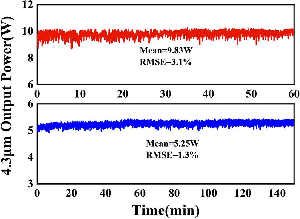
Figure 7 depicts the power stability of the mid-IR laser source at different output power levels. The source maintained an output power of 5.25 W for 150 minutes and 9.81 W for 60 minutes, with root mean square errors (RMSEs) of 3.1% and 1.3%, respectively, which confirms the long-term reliability of the CO2-filled HC-ARF laser source. However, the power stability degrades at higher output powers, primarily due to the coupling instability of high-power pump lasers and thermal collisions of gas molecules. Currently, challenges persist in achieving all-fiber splicing and high-power transmission between ultra-large-mode-area HCFs and solid-core fibers. Addressing the all-fiber integration and thermal management of gas-filled HCFs is expected to significantly improve the power stability of future mid-IR laser sources.
Long stability test for different output powers of the mid-IR laser source. Here RMSE denotes the root mean square deviation.

3.2 Output spectral characteristics of the mid-IR laser source
The output spectra of the CO2-filled HC-ARF laser source at 10.27 W are characterized using a mid-IR spectrometer (Thorlabs, OSA205), as illustrated in Figure 8(a). The spectrum exhibits two discrete narrow-band emission lines centered at 4299.39 nm (R(26)) and 4379.88 nm (P(28)), which align closely with the theoretical emission wavelengths of CO2 molecules. When the pump wavelength is tuned from the R(26) absorption line to the R(34) absorption line of the CO2 molecule, 10 emission lines spanning from 4290.96 to 4395.25 nm at the mid-IR laser source are generated, as illustrated in Figure 8(b). Due to the limited emission bandwidth of the gas medium at low pressure, the mid-IR laser source, despite achieving broad-range wavelength tuning, only permits stepwise tuning and lacks spectral continuity. Figure 8(c) presents the mid-IR laser emission spectrum, which varies with CO2 pressure under 15 W of effective pump power. As the pressure increases from 4.1 to 20 mbar, the intensity ratio of the R(26) to P(28) emission lines decreases gradually from 0.64 to 0, as shown in Figure 8(d). As the pressure increases, the collisional losses of the gas increase and the upper energy level lifetime decreases. Meanwhile, the R(26) emission line has a lower Einstein coefficient compared to the P(28) emission line; thus, the R(26) emission line is suppressed at higher pressure, leaving only the P(28) emission line.
(a) Emission spectra of the mid-IR laser source at an output power of 10.27 W. (b) Emission spectra of the mid-IR laser source under different pump wavelengths. (c) Emission spectra of the mid-IR source as a function of gas pressure. (d) Intensity ratio of the R(26) to P(28) emission lines versus gas pressure.

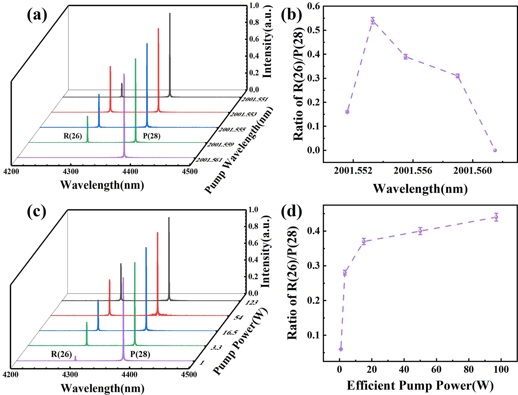
Figure 9(a) shows the trend of the mid-IR laser spectrum with the pump wavelength detuning from the absorption peak, under effective pump power of 15 W and CO2 pressure of 5.2 mbar. In the case of a pump wavelength of 2001.561 nm, the absorption of the pump laser by CO2 molecules is relatively low, resulting in a higher lasing threshold for the mid-IR laser source, where only the P(28) emission line exists. When the pump wavelength gradually approaches the gas absorption peak, the R(26) emission line emerges and intensifies, with its relative intensity ratio to the P(28) line reaching up to 0.54, as shown in Figure 9(b). Once the pump wavelength deviates from the absorption peak again, the R(26) line is suppressed once more. Figure 9(c) shows the spectral curves of the mid-IR laser source under different pump powers at 5.2 mbar pressure. We note that the intensity of the P(28) emission line far exceeds that of the R(26) line at a pump power of 1 W, with an intensity ratio of R(26) to P(28) of only 0.06. The primary reason for this low ratio is the smaller Einstein coefficient of the R(26) line compared to that of P(28). Consequently, the P(28) transition launches first and extracts the limited population of the upper energy level, thereby suppressing the emission of the R(26) line. Since the pump power is gradually increased, the R(26) emission line experiences amplification. Then, the intensity ratio of R(26) to P(28) rises to 0.44 under a pump power of 123 W.
(a) Evolution of the emission spectrum of a mid-IR laser source with the pump wavelength detuned from the absorption peak. (b) Relative intensity ratio of the R(26) to P(28) emission lines versus the detuning of the pump wavelength from the absorption peak. (c) Evolution of the emission spectrum of a mid-IR laser source with the pump power. (d) Relative intensity ratio of the R(26) to P(28) emission lines versus the pump power.

3.3 Pulse characteristics of the mid-IR laser source
To evaluate the temporal characteristics of the CO2-filled HC-ARF nanosecond pulse laser source, an extended HgCdTe photodetector (Thorlabs, PDAVJ10; 100 MHz bandwidth) and a high-speed oscilloscope (Agilent Technologies, DSO-X 92504A, 25 GHz) are employed to measure the pulse train and single pulse profile. The output power of 10.27 W is attenuated to yield a photodetector output of 10 mV DC voltage. As shown in Figure 10(a), the time interval between adjacent pulses is 100 ns, corresponding to a repetition rate of 10 MHz, which is consistent with the pump pulse repetition rate. Remarkably, the pulse intensity exhibits certain fluctuations, indicating compromised stability of the 4.3 μm high-power pulse laser, within a 1 μs time region. This fluctuation in pulse intensity is likely to arise from rapid collisions of gas molecules under high-power operation. Figure 10(b) gives the recorded single pulse profile with a full width at half maximum (FWHM) of 29 ns. Note that the pulse width of the 4.3 μm laser has undergone some narrowing compared to the pump pulse. This is because the pump pulse excites a large population of upper energy level during the pumping period. When population inversion is formed between the upper and lower energy levels, the signal pulse generated within the HCF gradually undergoes a stimulated emission process, rapidly depleting the population in the upper energy level. Due to the fast rate of stimulated emission and the limited number of inverted populations, the mid-IR laser pulse width experiences slight narrowing.
(a) Pulse train and (b) single pulse profile of the mid-IR laser source.

3.4 Beam quality characteristics of the mid-IR laser source
To evaluate the beam quality performance of the 4.3 μm nanosecond pulse laser, we first characterize the beam quality of the 2 μm pump laser output from the HCF utilizing the knife-edge technique at a pump power of 1 W. As shown in Figure 11(a), the 2 μm pump laser with an initial beam quality factor of 1.15 experiences degradation to a value of 4.45 after transmission through the gas cell and HCF. This deterioration in pump laser beam quality can be attributed to two primary factors. On one hand, it relates to the gas cell sealing process: the solidification of external adhesive during sealing imposed significant stress on the HC-ARF, causing structural deformation within the HC-ARF and consequently leading to degradation of laser transmission modes[ Reference Zhang, Peng, Dong, Yao, Hou and Wang25]. On the other hand, the HC-ARF is designed as a multimode fiber, allowing the pump laser coupled into it to excite higher-order modes. The subsequent low-loss transmission of these modes results in the degradation of beam quality. Figure 11(b) illustrates the beam quality of the 4.45 μm nanosecond pulse laser at the output of the HC-ARF. The value, obtained by polynomial fitting of the measured data, is M 2 = 1.42. Compared to the 2 μm pump laser, the beam quality of the 4.3 μm signal laser shows significant improvement, which may be attributed to the increased transmission loss of higher-order modes in the HC-ARF within the mid-IR wavelength range.
(a) Beam quality of the 2 μm pump laser after transmission through the gas cell and HCF. (b) Beam quality of the 4.3 μm nanosecond pulse laser source.

4 Conclusion
In conclusion, we have reported a 10-W-level 4.3 μm nanosecond pulse laser source in a CO2-filled HC-ARF based on a population inversion scheme. In the experiment, a pumping scheme detuned from the gas absorption peak is adopted to enhance the conversion efficiency of CO2 molecules under high-power laser pumping. Under the pump power of 125 W, a 4.3 μm nanosecond pulse with an average power of 10.27 W, a pulse energy of 1.027 μJ, a pulse width of 29 ns and a peak power of 354 W is obtained. Compared to the results under absorption peak pumping, the output power and optical-to-optical slope efficiency of the 4.3 μm laser source are increased by 11.75% and 2.52%, respectively. To the best of our knowledge, this represents the highest output power of a CO2-filled HC-ARF nanosecond pulse laser source in the 4.3 μm band. We believe such a high-performance mid-IR gas-filled HCF laser source is expected to find wide applications in many fields, such as opto-electronic countermeasures and gas sensing.
Acknowledgements
This work was supported by the National Natural Science Foundation of China (Grant Nos. U2241225, 62405011 and 62035002), the Beijing Natural Science Foundation (Grant No. 1264062) and the Fundamental Research Funds for Beijing Municipal Universities (Grant No. 312000546325001).





 Open access

