





1. Introduction
The hydrodynamic forces on hydrofoils are determined primarily by flow separation (if present), the Froude number of the flow and the submergence of the array (Acosta Reference Acosta1973). Most investigations (Faltinsen Reference Faltinsen2005; Molland & Turnock Reference Molland and Turnock2022) consider single hydrofoils or short tandem arrays. There appear to be few, if any, analytical descriptions of the flow past near-surface hydrofoil cascades. The earliest relevant theoretical work is that modelling turbine blades as a periodic array of flat plates (Joukovskii Reference Joukovskii1890; König Reference König1922; Kawada Reference Kawada1930) at a prescribed angle of attack in an unbounded fluid. The purpose of the present paper is to extend these analyses, following Marshall & Johnson (Reference Marshall and Johnson2023, MJ23 herein), to include the effect of proximity to a free surface. Progress is made by restricting attention to flows at infinite Froude number thus obtaining the flow fields and forces in closed form, and allowing discussion of the effect of arbitrary array submergence and foil separation. It will be shown that the disturbance to the free surface decreases as the interfoil separation decreases leading to substantially higher lift per hydrofoil. Further, the flow over a hydrofoil array approaches its infinite submergence form significantly more rapidly the smaller the interfoil separation.
Section 2 formulates the problem. Section 3 obtains the solution using a method related to that of Michell (Reference Michell1890) and Joukovskii (Reference Joukovskii1890). The multiply connected flow domain, in the complex  $z$-plane, is conformally mapped, by a mapping to be determined, to a concentric annulus in an auxiliary complex $\zeta$-plane. The complex flow potential $w(z)$ and its derivative $w'(z)$ are obtained in terms of $\zeta$ by considering their form at known points in the flow, as in Chaplygin's method of special points (Gurevitch Reference Gurevitch1965, § 5). The required conformal mapping is then determined here by explicit integration. Semenov & Wu (Reference Semenov and Wu2020) use this method to obtain an integral equation formulation for isolated submerged obstacles. Crowdy & Green (Reference Crowdy and Green2011), Crowdy, Llewellyn Smith & Freilich (Reference Crowdy, Llewellyn Smith and Freilich2013) and subsequent co-workers use a related method to discuss hollow vortices. Section 4 shows that in this limit, due to the absence of surface waves and separation, the drag on the foils vanishes and obtains the lift as a function of the angle of attack, depth of submergence and foil separation. Section 5 describes surface profiles, flow patterns and force predictions. A reader who is mainly interested in the properties of the flow solutions obtained could initially omit the analytical details of §§ 2–4 and begin at § 5. Section 6 summarises the minimum numerical computation required to obtain the lift coefficient and reproduce the examples presented in § 5 and then briefly discusses the results.
2. Problem formulation
We consider the steady, planar, free-surface, attached flow of a fluid of infinite depth past a periodic row of submerged hydrofoils, which we model as flat plates – i.e. straight line segments, or, slits – of finite length. We assume the fluid to be inviscid and incompressible, and the flow to be irrotational. We also assume an infinite Froude number, i.e. we ignore the effect of gravity on the free surface, and ignore surface tension, whose effect is negligible on typical hydrofoil scales. We consider the flow domain to lie in a complex  $z$-plane, where $z=x+\mathrm {i}y$. We denote this domain by $D$. It is a periodic domain. An example is sketched in figure 1. We denote the free surface of $D$ by $\partial D_0$. The shape of $\partial D_0$ is unknown a priori but will be determined as part of our solution. We denote the period of the row of hydrofoils (and hence of $D$) – i.e. the interfoil separation – by $\lambda$ ( $\in \mathbb {R},>0$). We denote the angle of the hydrofoils to the positive $x$-direction measured at their leading endpoints (or, edges) by $\alpha$, so $-\alpha$ gives their angle of attack. We consider $\alpha$ over the range $(-{\rm \pi} /2,{\rm \pi} /2)$. The case of a row of horizontal hydrofoils – i.e. $\alpha =0$ – is trivial (the foils do not disturb the flow past them), and thus we henceforth ignore it, although we will retrieve it later as a limiting case of our results – see § D.1. We will also not consider rows of strictly vertical hydrofoils, i.e. $\alpha =\pm {\rm \pi}/2$; this is because our analysis relies on the foils having trailing endpoints, where we will be imposing the Kutta condition. However, we will present limits of our results for which $\alpha \rightarrow \pm {\rm \pi}/2$ – see § D.2. For the example sketched in figure 1, $-{\rm \pi} /2<\alpha <0$, so the angle of attack is positive. Without loss of generality, we normalise the hydrofoils to be of unit length. Furthermore, we fix the leading endpoint of one of the hydrofoils to be at the origin. We denote this foil by $\partial D_1$ and its leading endpoint by $z_1$. We denote the trailing endpoint of $\partial D_1$ by $z_2$, so $z_2=\mathrm {e}^{\mathrm {i}\alpha }$.
Sketch of a section of the flow domain  $D$ for a free-surface flow of a fluid of infinite depth past a periodic row of submerged hydrofoils in a complex $z$-plane ( $z=x+\mathrm {i}y$). $\partial D_0$ denotes the free surface (in blue). The hydrofoils (red) are modelled as slits of unit length. $\lambda$ denotes the period of the row of hydrofoils (and hence of $D$).
$D$).  $\alpha$ denotes the angle of the foils to the positive $x$-direction measured at their leading endpoints, so $-\alpha$ gives their angle of attack. (For the case sketched, $-{\rm \pi} /2<\alpha <0$.) $\partial D_1$ denotes one of the foils whose leading and trailing endpoints lie at $z_1=0$ and $z_2=\mathrm {e}^{\mathrm {i}\alpha }$, respectively. $z_3$ denotes a stagnation point on the leading face of $\partial D_1$. $z_c$ denotes a local extremum of $\partial D_0$ (a peak when $-{\rm \pi} /2<\alpha <0$; a trough when $0<\alpha <{\rm \pi} /2$) and $y_c$ denotes its imaginary part which we define to be the leading-edge submergence of the foils. $D$ extends to infinity horizontally in both directions and vertically downwards.

We represent the velocity field of the flow by the vector  $(u(x,y),v(x,y))$. We assume that as $y\rightarrow -\infty$, the flow is uniform and in the positive $x$-direction, i.e. to leading order,
 \begin{equation} (u(x,y),v(x,y))\sim (U_{\infty},0)\quad\mbox{as } y\rightarrow-\infty \end{equation}
for some real constant  $U_{\infty }>0$. We can define a complex potential, $w(z)=\phi (x,y)+\mathrm {i}\psi (x,y)$, for the flow, where $\phi (x,y)$ and $\psi (x,y)$ are the associated velocity potential and streamfunction, respectively. Here, $w(z)$ possesses the following properties. It is analytic in the interior of $D$ and $w'(z)=u(x,y)-\mathrm {i}v(x,y)$ gives the complex velocity, where here and throughout this paper, we use $'$ with respect to a function of a single variable to denote the function's derivative. It follows from (2.1) that, to leading order,
 \begin{equation} w(z)\sim U_{\infty}z\quad\mbox{as } y\rightarrow-\infty. \end{equation}
One may also deduce that for  $z\in D$,
 \begin{equation} w(z+\lambda)=w(z)+\varphi_{\lambda} \end{equation}
for some (real) constant  $\varphi _{\lambda }$. Next, since $\partial D_0$ and $\partial D_1$ are both streamlines of the flow, $\mathrm {Im}\{w(z)\}$ must be constant along them, i.e.
 \begin{equation} \mathrm{Im}\{w(z)\}=\psi_j\quad\mbox{for}\ z\in\partial D_j,\enspace j=0,1, \end{equation}
for some constants  $\psi _0$ and $\psi _1$. For the same reason, one may deduce that
 \begin{equation} \mathrm{Im}\{\mathrm{e}^{\mathrm{i}\alpha}w'(z)\}=0\quad\mbox{for } z\in \partial D_1. \end{equation}
Furthermore, it follows from Bernoulli's equation and our assumption of an infinite Froude number and zero surface tension that
 \begin{equation} |w'(z)|=U_0\quad\mbox{for } z\in \partial D_0, \end{equation}
for some constant  $U_0$. Here, $U_0$ will tend to $U_{\infty }$ as $\lambda$ tends to infinity, i.e. in the limit of flow past just a single hydrofoil (as considered by MJ23). In addition, one may deduce that for $z$ local to the leading endpoint, $z_1$ ( $=0$), of $\partial D_1$, to leading order,
 \begin{equation} w'(z)\sim Az^{{-}1/2} \end{equation}
for some constant  $A$. Thus, the velocity field is singular at $z_1$. To ensure that the velocity field is bounded at the trailing endpoint, $z_2$, of $\partial D_1$, we impose the Kutta condition there, thus assuming a certain circulation $\varGamma$, say, around each of the hydrofoils, so
 \begin{equation} \oint_{\mathcal{C}} \mathrm{d}w(z)=\varGamma, \end{equation}
where  $\mathcal {C}$ is a simple closed contour that contains $\partial D_1$ (but none of the other foils) in its interior and itself lies entirely in the interior of $D$, and we integrate around $\mathcal {C}$ in the anticlockwise direction. Finally, one may also deduce that there must be a single stagnation point of the flow on the leading face of each foil. We assume these to be the only stagnation points of the flow. We denote the stagnation point on $\partial D_1$ by $z_3$. More specifically, one may deduce that for $z$ local to $z_3$, to leading order,
 \begin{equation} w'(z)\sim B (z-z_3) \end{equation}
for some constant  $B$.
$B$.
3. A conformal parametrisation
We will seek  $D$ as the image of a domain $D_{\zeta }$ in a complex $\zeta$-plane, under a conformal map $z(\zeta )$. More specifically, we take $D_{\zeta }$ to be the concentric annulus that is bounded by the circles $C_0$ and $C_1$ that are centred on the origin and of radius $1$ and $q$, respectively, for some $q$ with $0< q<1$. An example is sketched in figure 2. We let $\zeta _{\infty }=-\mathrm {i}\beta$ for some real $\beta$ with $q<\beta <1$. We assume that for $\zeta$ local to $\zeta _{\infty }$, to leading order,
 \begin{equation} z(\zeta)\sim\frac{\mathrm{i}\lambda}{2{\rm \pi}}\log(\zeta+\mathrm{i}\beta). \end{equation}
So  $z(\zeta )$ maps $\zeta _{\infty }$ to the point at infinity; more specifically, as $\zeta \rightarrow \zeta _{\infty }$, so $\mathrm {Im}\{z(\zeta )\}\rightarrow -\infty$ while $\mathrm {Re}\{z(\zeta )\}$ remains bounded. The map $z(\zeta )$ will be multivalued in $D_{\zeta }$. In particular, $z(\zeta )$ will increase by $\lambda$ as $\zeta$ completes a single circuit of $C_0$ in the clockwise direction. As one may deduce from the form that we are going to construct for $z(\zeta )$ (see (3.37)), a single-valued branch of it may be obtained by the introduction of a branch cut along a simple line segment that joins $\zeta _{\infty }$ to a point on $C_0$. Each such branch maps this ‘cut’ $D_{\zeta }$ onto a different period cell of $D$. However, we will not need to specify such a cut – or, indeed, the precise boundaries of any period cell of $D$ – for our subsequent analysis. We assume that $\partial D_0$ is the image under $z(\zeta )$ of $C_0$, while $\partial D_1$ – and all the other hydrofoils – are the images of $C_1$. Finally, for $j=1,2,3$, we denote the pre-image of $z_j$ by $\zeta _j$, which lies on $C_1$. In general, we will need to solve for $\zeta _j$, $j=1,2,3$ with the real values of $q$,
$q$,  $\arg \{\zeta _1\}$, $\arg \{\zeta _2\}$, $\beta$ and a constant determining $z(0)$ becoming the unknowns in the problem, to be solved for in terms of $\lambda$, $\alpha$ and $U_{\infty }$ as described in § 3.5.
Sketch of the pre-image domain,  $D_{\zeta }$, for our conformal parametrisation of the flow domain $D$ as in figure 1. $D$ is the image of $D_{\zeta }$ under a conformal map, $z(\zeta )$.

One may deduce (on purely geometrical grounds) that  $z'(\zeta )$ has simple zeros at both $\zeta =\zeta _1$ and $\zeta _2$. For the example shown in figure 2, $\zeta _3$ lies on the section of $C_1$ that is traversed in passing from $\zeta _1$ to $\zeta _2$ in the anticlockwise direction (which is the case for a row of hydrofoils with a positive angle of attack). However, our subsequent analysis makes no assumption on the ordering of $\zeta _1$, $\zeta _2$ and $\zeta _3$ around $C_1$.
Now, in terms of  $\zeta$, we have
 \begin{equation} w(z)=W(\zeta),\quad w'(z)=\varOmega(\zeta), \end{equation}
for some functions  $W$, the complex potential in $D_{\zeta }$, and $\varOmega$, the complex velocity mapped to $D_{\zeta }$. We will construct formulae (in terms of $\zeta$) for $W(\zeta )$ and $\varOmega (\zeta )$, and then make use of the fact that (Joukovskii Reference Joukovskii1890; Michell Reference Michell1890)
 \begin{equation} z'(\zeta)=\frac{\mathrm{d}W/\mathrm{d}\zeta}{\mathrm{d}w/\mathrm{d}z}=\frac{W'(\zeta)}{\varOmega(\zeta)}, \end{equation}
to construct a formula for  $z(\zeta )$. A similar construction is used to obtain the hollow vortex solutions of Crowdy & Green (Reference Crowdy and Green2011) and Crowdy et al. (Reference Crowdy, Llewellyn Smith and Freilich2013) although there, the integration of the analogue of the right-hand side of (3.3) is performed numerically, in contrast to the analytical result for $z(\zeta )$ that we derive below – see (3.37) – and that obtained by MJ23. The construction that we use here and our results are natural extensions of those of MJ23. Indeed, one can retrieve the results of MJ23 by taking the limit of our results as $\lambda \rightarrow \infty$ with $\beta \rightarrow 1$, as we describe in more detail later.
3.1. Some special functions
We will perform our construction in terms of certain special functions, labelled here as  $P$ and $K$. We define these and state their relevant properties in this section. We refer the reader to MJ23 and Crowdy (Reference Crowdy2020) for further discussion of these functions.
To begin, we define the transformation  $\theta _n(\zeta )=q^{2n}\zeta$ for all $n\in \mathbb {Z}$ (note that $\theta _0(\zeta )=\zeta$ is the identity transformation), and the set $\varTheta =\{\theta _n(\zeta )\,|\,n\in \mathbb {Z}\}$. Next, we introduce $D_{\zeta }^{-1}$ to denote the reflection of $D_{\zeta }$ in $C_0$, where by reflection in $C_0$, we mean the transformation $\zeta \mapsto 1/\bar {\zeta }$. Here, $D_{\zeta }^{-1}$ is the annular domain bounded by the circles $C_0$ and $C_{-1}$, where the latter denotes the reflection of $C_1$ in $C_0$ and is centred on the origin and of radius $1/q$ (see figure 3). We define $F$ to be the region that consists of the union of $\overline {D_{\zeta }}$ and $D_{\zeta }^{-1}$ where we use the ‘overline’ notation with respect to a domain to denote the domain's closure, i.e.
 \begin{equation} F=\{\zeta:q\leq|\zeta|< q^{{-}1}\}, \end{equation}
so  $F$ does not contain $C_{-1}$. The images of $F$ under all elements of $\varTheta$ are mutually disjoint and cover the whole of the $\zeta$-plane, except for the origin and the point at infinity. Here, $\varTheta$ is an example of a Schottky group (Ford Reference Ford1972; Crowdy Reference Crowdy2020). Additionally, $F$ is referred to as a fundamental region of $\varTheta$. (The fundamental region of a Schottky group is not unique.)
The annuli appearing in the analysis.  $D_{\zeta }^{-1}$ (light grey) is the reflection of the pre-image domain $D_{\zeta }$ (turquoise) of figure 2 in the unit circle $C_0$ (dotted blue). The union of $\overline {D_{\zeta }}$ and $D_{\zeta }^{-1}$ forms the fundamental region $F$ of (3.4) for the group $\varTheta$. The union of $\bar {F}$ and the reflection of $F$ (dark grey) in the circle $C_1$ (dotted red) forms the fundamental region $\hat {F}$ of (3.10) for the group $\hat {\varTheta }$. The complex velocity $W'(\zeta )$ has simple poles (blue crosses) at $\zeta =-\mathrm {i}\beta, -\mathrm {i}/\beta, -\mathrm {i}q^2\beta$ and $-\mathrm {i}q^2/\beta$, and simple zeros (blue circles) at $\zeta =\zeta _2$, $-\overline {\zeta _2}$, $1/\overline {\zeta _2}$ and $-1/\zeta _2$. ( $-\overline {\zeta _2}=\zeta _3$ – see (3.25).) The mapped complex velocity $\varOmega (\zeta )$ has simple poles (red crosses) at $\zeta =\zeta _1$ and $-1/\zeta _2$ (coinciding with a zero of $W'(\zeta )$), and simple zeros (red discs) at $\zeta =1/\overline {\zeta _1}$ and $-\overline {\zeta _2}$ (also coinciding with a zero of $W'(\zeta )$).

Now, the function  $P(\zeta,q)$ is defined for all complex $\zeta$ and (real) $q$ with $0< q<1$, by
 \begin{equation} P(\zeta,q)=(1-\zeta)\prod_{n=1}^{\infty}(1-q^{2n}\zeta)(1-q^{2n}\zeta^{{-}1}). \end{equation}
Here,  $P(\zeta,q)$ is, up to a normalisation, the Schottky–Klein prime function associated with $\varTheta$. One can check that $P(\zeta,q)$ is analytic everywhere in $F$, and is non-zero in $F$ except for a simple zero at $\zeta =1$. Furthermore, one can deduce directly from (3.5) that
 \begin{equation} P(q^2\zeta,q)={-}\zeta^{{-}1}P(\zeta,q),\quad P(\zeta^{{-}1},q)={-}\zeta^{{-}1}P(\zeta,q). \end{equation}
Relation (3.6a) can be used to continue  $P(\zeta,q)$ to points $\zeta$ outside of $F$. In particular, one can deduce from (3.6a) and the properties of $P(\zeta,q)$ for $\zeta \in F$ noted above that $P(\zeta,q)$ is analytic everywhere in the $\zeta$-plane except for essential singularities at the origin and the point at infinity, and that it has simple zeros at $\zeta =q^{2n}$ for all $n\in \mathbb {Z}$. Of course, one could also deduce these properties directly from (3.5).
Next, the function  $K(\zeta,q)$ is defined by
 \begin{equation} K(\zeta,q)=\zeta\frac{\mathrm{d}}{\mathrm{d}\zeta}\log P(\zeta,q). \end{equation}
It follows from (3.5) that
 \begin{equation} K(\zeta,q)=\frac{1}{\zeta-1}+1+\sum_{n=1}^{\infty} q^{2n} \left(\frac{1}{\zeta-q^{2n}}-\frac{1}{\zeta^{{-}1}-q^{2n}}\right). \end{equation}
One can check that  $K(\zeta,q)$ is analytic everywhere in $F$ except for a simple pole at $\zeta =1$ with residue $1$. Also, it follows from (3.6a,b) that
 \begin{equation} K(q^2\zeta,q)=K(\zeta,q)-1,\quad K(\zeta^{{-}1},q)=1-K(\zeta,q). \end{equation}
 In addition to the above, we will also make use of the functions  $P(\zeta,q^2)$ and $K(\zeta,q^2)$. Of course, with $0< q<1$, we also have $0< q^2<1$, and so $P(\zeta,q^2)$ is defined by (3.5) simply with $q$ replaced by $q^2$. $P(\zeta,q^2)$ is (up to a normalisation) the Schottky–Klein prime function associated with $\hat {\varTheta }=\{\theta _{2n}(\zeta )\,|\,n\in \mathbb {Z}\}$, which is a subgroup of $\varTheta$ and itself a Schottky group (Vasconcelos, Marshall & Crowdy Reference Vasconcelos, Marshall and Crowdy2015). A fundamental region of $\hat {\varTheta }$ is
 \begin{equation} \hat{F}=\{\zeta:q^3<|\zeta|\leq q^{{-}1}\}, \end{equation}
i.e. the region that consists of the union of  $\bar {F}$ and the reflection of $F$ in the circle $C_1$, where reflection in $C_1$ is given by $\zeta \mapsto q^2/\bar {\zeta }$ (see figure 3).
It follows directly from (3.5) that
 \begin{equation} P(\zeta,q)=P(\zeta,q^2)P(q^2\zeta,q^2), \end{equation}
and hence from (3.7) that
 \begin{equation} K(\zeta,q)=K(\zeta,q^2)+K(q^2\zeta,q^2). \end{equation}
3.2. Constructing the complex potential  $W(\zeta )=w(z)$

The construction of  $W(\zeta )$ is straightforward as it is simply the complex potential for flow in the annulus $D_{\zeta }$ driven by a point vortex at $-\mathrm {i}\beta$ and having circulation $\varGamma$ around $C_1$, with stagnation points at $\zeta _2$ and $\zeta _3$, as we now demonstrate.
It follows from the properties of  $w(z)$ and $z(\zeta )$ noted above that $W(\zeta )$ must be analytic for all $\zeta \in D_{\zeta }$ except that (as follows from (2.2) and (3.1)) for $\zeta$ local to $-\mathrm {i}\beta$, to leading order,
 \begin{equation} W(\zeta)\sim\frac{\mathrm{i}\lambda U_{\infty}}{2{\rm \pi}}\log(\zeta+\mathrm{i}\beta), \end{equation}
i.e.  $W(\zeta )$ must have a point vortex singularity at $\zeta =\mathrm {-i}\beta$. Also, it follows from (2.4) that
 \begin{equation} \mathrm{Im}\{W(\zeta)\}=\psi_j\quad\mbox{for } \zeta\in C_j, j=0,1. \end{equation}
Furthermore, it follows from (2.8) that
 \begin{equation} \oint_{\mathcal{C}_{\zeta}} \mathrm{d}W(\zeta)=\varGamma,\end{equation}
where  $\mathcal {C}_{\zeta }$ is a simple closed contour that contains $C_1$ but not $\zeta =-\mathrm {i}\beta$ in its interior, and itself lies entirely in the interior of $D_{\zeta }$, and we integrate around $\mathcal {C}_{\zeta }$ in the anticlockwise direction. Recall that $\varGamma$ is still to be determined. Furthermore, it follows from (2.3) and (3.1) that
 \begin{equation} \oint_{\mathcal{C}_{\zeta}^{\infty}} \mathrm{d}W(\zeta)={-}\varphi_{\lambda}, \end{equation}
where  $\mathcal {C}_{\zeta }^{\infty }$ is a simple closed contour that contains $\zeta =-\mathrm {i}\beta$ in its interior, and itself lies entirely in the interior of $D_{\zeta }$, and we integrate around $\mathcal {C}_{\zeta }^{\infty }$ in the anticlockwise direction.
The required point vortex solution can be expressed as a ratio of elliptic functions but for later analysis, it is convenient to use the equivalent prime function form
 \begin{equation} W(\zeta)=\frac{\mathrm{i}\lambda U_{\infty}}{2{\rm \pi}} \log\left(\frac{P(\mathrm{i}\zeta/\beta,q)}{P(\mathrm{i}\beta\zeta,q)}\right)- \frac{\mathrm{i}\varGamma}{2{\rm \pi}}\log\zeta.\end{equation}
One can verify that  $W(\zeta )$ as given by (3.17) possesses the properties stated above as follows. First, it follows from the properties of $P(\zeta,q)$ that $W(\zeta )$, as given by (3.17), is analytic for all $\zeta \in D_{\zeta }$ except for a logarithmic singularity at $\zeta =-\mathrm {i}\beta$ of the form required by (3.13). It is also evident that this form for $W(\zeta )$ satisfies (3.15) and (3.16) (the latter with $\varphi _{\lambda }=\lambda U_{\infty }$). Finally, to check the boundary conditions (3.14), it is helpful to first note that
 \begin{equation} \left|\frac{P(\mathrm{i}\zeta/\beta,q)}{P(\mathrm{i}\beta\zeta,q)}\right|^2 =\frac{P(\mathrm{i}\zeta/\beta,q)P(-\mathrm{i}/(\beta\zeta),q)}{P(\mathrm{i} \beta\zeta,q)P(-\mathrm{i}\beta/\zeta,q)}=\frac{1}{\beta^2}\quad\mbox{for } \zeta\in C_0, \end{equation}
where the first equality follows from the fact that for  $\zeta \in C_0$, $\bar {\zeta }=1/\zeta$, and the second follows from (3.6b). Similarly,
 \begin{equation} \left|\frac{P(\mathrm{i}\zeta/\beta,q)}{P(\mathrm{i}\beta\zeta,q)}\right|^2 =\frac{P(\mathrm{i}\zeta/\beta,q)P(-\mathrm{i}q^2/(\beta\zeta),q)}{P(\mathrm{i} \beta\zeta,q)P(-\mathrm{i}q^2\beta/\zeta,q)}=1\quad\mbox{for } \zeta\in C_1, \end{equation}
where now the first equality follows from the fact that for  $\zeta \in C_1$, $\bar {\zeta }=q^2/\zeta$, and the second follows by using both of (3.6a,b). Then, one may deduce that (3.14) holds (with $\psi _0=-(\lambda U_{\infty }/(2{\rm \pi} ))\ln \beta$ and $\psi _1=-(\varGamma /(2{\rm \pi} ))\ln q$). This completes our verification of (3.17). Similar arguments to those used below for $\varOmega (\zeta )$ show that $W(\zeta )$ is unique.
Finally, we determine  $\varGamma$. Differentiating (3.17) gives
 \begin{equation} W'(\zeta)=\frac{\mathrm{i}\lambda U_{\infty}}{2{\rm \pi}\zeta} (K(\mathrm{i}\zeta/\beta,q)-K(\mathrm{i}\beta\zeta,q)) -\frac{\mathrm{i}\varGamma}{2{\rm \pi}\zeta}. \end{equation}
Now, to impose the Kutta condition at the trailing endpoint  $z_2$, we must choose $\varGamma$ such that $W'(\zeta _2)=0$, giving
 \begin{equation} \varGamma=\lambda U_{\infty}(K(\mathrm{i}\zeta_2/\beta,q)-K(\mathrm{i}\beta\zeta_2,q)). \end{equation}
(It follows from (3.22) that the quantity on the right-hand side of (3.21) is real.) Figure 4(a) shows contours of  $W(\zeta )$ – i.e. flow streamlines – in $D_{\zeta }$ as given by (3.17) for a typical solution. The flow field is symmetric about the ${\rm Im}\,\zeta$ axis, reflecting the symmetry of the boundaries and the vortex.
The solution components for a typical solution (figure 5(c) below). (a) Contours of  $\mathrm {Im}\{W(\zeta )\}$ as given by (3.17), giving the flow streamlines in the pre-image domain $D_{\zeta }$ with a point vortex at $\zeta =\mathrm {-i}\beta$ (which corresponds to the point at infinity in $D$), stagnation points symmetrically at $\zeta =\zeta _2$ (the trailing edges in $D$) and $-\overline {\zeta _2}$ (on the leading faces in $D$), and tangential flow along $C_0$ (the free surface of $D$) and $C_1$ (the foils). (b) Isotachs, contours of $|\varOmega (\zeta )|$ as given by (3.29), the flow speed mapped to the pre-image domain $D_{\zeta }$, with infinite speed at $\zeta _1$ (the leading edges in $D$), a single stagnation point at $\zeta =-\overline {\zeta _2}$ and constant speed along $C_0$, with no stagnation point at $\zeta =\zeta _2$ where the speed is finite.

3.2.1. Properties of $W'(\zeta )$, the complex velocity in $D_\zeta$


We now note some properties of  $W'(\zeta )$ that will be useful later. First, $W'(-\overline {\zeta _2})=0$. This follows from (3.20) using the fact that $W'(\zeta _2)=0$ and
 \begin{equation} K(-\mathrm{i}\overline{\zeta_2}/\beta,q)-K(-\mathrm{i}\beta\overline{\zeta_2},q) =K(\mathrm{i}\zeta_2/\beta,q)-K(\mathrm{i}\beta\zeta_2,q), \end{equation}
where the latter follows by using the fact that  $\overline {\zeta _2}=q^2\zeta _2$ and both of (3.9a,b). We henceforth assume that $-\overline {\zeta _2}\neq \zeta _2$, or equivalently, that $\zeta _2\neq \pm \mathrm {i}q$ (although in § D.2, we will consider the limit of our results as $\zeta _2\rightarrow \pm \mathrm {i}q$ whilst $\zeta _1\rightarrow \mp \mathrm {i}q$). We now claim that the zeros of $W'(\zeta )$ at $\zeta =\zeta _2$ and $-\overline {\zeta _2}$ are the only zeros of $W'(\zeta )$ in $F$, and are simple zeros. To demonstrate this, note that it follows from (3.20) and (3.9a) that
 \begin{equation} W'(q^2\zeta)=\frac{1}{q^2}W'(\zeta). \end{equation}
Thus,
 \begin{equation} \mathrm{d}\log W'(q^2\zeta)=\mathrm{d}\log W'(\zeta). \end{equation}
It then follows from (3.24) and an application of the Argument Principle (Ahlfors Reference Ahlfors1979, § 5.2) that  $W'(\zeta )$ has the same number of poles as zeros in $F$, where these are both counted according to their multiplicities. ( $\zeta _2$ and $-\overline {\zeta _2}$ lie on the boundary of $F$, but by standard arguments, one can adapt the Argument Principle to take account of this.) However, it follows from (3.20) and the properties of $K(\zeta,q)$ that $W'(\zeta )$ has simple poles at $\zeta =-\mathrm {i}\beta$ and $-\mathrm {i}/\beta$, and no other singularities in $F$. Thus, as claimed, the zeros of $W'(\zeta )$ at $\zeta =\zeta _2$ and $-\overline {\zeta _2}$ must be the only zeros of $W'(\zeta )$ in $F$, and must be simple zeros. It also then follows that
 \begin{equation} \zeta_3={-}\overline{\zeta_2}. \end{equation}
(One could also deduce (3.25) from the symmetry of this flow in  $D_{\zeta }$.)
Finally, one may also deduce that  $W'(\zeta )$ is analytic for all $\zeta \in \hat {F}$ except for simple poles at $\zeta =-\mathrm {i}\beta, -\mathrm {i}/\beta, -\mathrm {i}q^2\beta$ and $-\mathrm {i}q^2/\beta$, and that the only zeros of $W'(\zeta )$ in $\hat {F}$ are simple zeros at $\zeta =\zeta _2, -\overline {\zeta _2}, 1/\overline {\zeta _2}$ and $-1/\zeta _2$ – see figure 3. ( $W'(\zeta )$ also has zeros at $\zeta =q^2\zeta _2$ and $-q^2\overline {\zeta _2}$, but both of these points have modulus $q^3$ and so are not contained in $\hat {F}$.)
3.3. Constructing the mapped complex velocity $\varOmega (\zeta )=w'(z)$

It follows from the properties of  $w'(z)$ and $z(\zeta )$ stated above that $\varOmega (\zeta )$ must be analytic for all $\zeta \in D_{\zeta }$ except for a simple pole at $\zeta =\zeta _1$ (as follows from (2.7) and the fact that $z'(\zeta )$ has a simple zero at $\zeta _1$). Furthermore, $\varOmega (\zeta )$ must be non-zero for all $\zeta$ in the closure of $D_{\zeta }$ except for a simple zero at $\zeta =-\overline {\zeta _2}$ (as follows from (2.9), recalling (3.25)). We henceforth assume that $\zeta _1\neq -\overline {\zeta _2}$ (although in § D.1, we will consider the limit of our results as $\zeta _1\rightarrow -\overline {\zeta _2}$). Note that $\varOmega (\zeta )$ is non-zero at $\zeta =\zeta _2$ – i.e. $w'(z)$ is non-zero at the trailing endpoint, $z_2$, of the hydrofoil – because $W'(\zeta )$ and $z'(\zeta )$ both have simple zeros at $\zeta =\zeta _2$ (and $\varOmega (\zeta )=W'(\zeta )/z'(\zeta )$). In addition, it follows from (2.5) and (2.6) that
 \begin{equation} |\varOmega(\zeta)|=U_0\quad\mbox{for } \zeta\in C_0,\quad \mathrm{Im}\{\mathrm{e}^{\mathrm{i}\alpha}\varOmega(\zeta)\}=0\quad\mbox{for } \zeta\in C_1,\end{equation}
and from (2.2) that
 \begin{equation} \varOmega(-\mathrm{i}\beta) = U_{\infty}. \end{equation}
These are also properties of the mapped complex velocity – also labelled as  $\varOmega (\zeta )$ – that is constructed by MJ23, with the exception that the equivalent of (3.26a) and (3.27) in MJ23 ((3.28a) and (3.29) of the latter) have the same constant (labelled $U$) on their right-hand sides, and the equivalent of (3.27) holds at $\zeta =-\mathrm {i}$ rather than $-\mathrm {i}\beta$. Then, by using exactly the same arguments as those used in MJ23, one may deduce that $\varOmega (\zeta )$ is analytic for all $\zeta \in \hat {F}$ except for simple poles at $\zeta =\zeta _1$ and $-1/\zeta _2$. Furthermore, the only zeros of $\varOmega (\zeta )$ in $\hat {F}$ are simple zeros at $\zeta =-\overline {\zeta _2}$ and $1/\overline {\zeta _1}$. In addition, one can show that
 \begin{equation} \varOmega(q^4\zeta)=\varOmega(\zeta), \end{equation}
from which one may deduce that  $\varOmega (\zeta )$ is automorphic with respect to the group $\hat {\varTheta }$. The property (3.28), together with the properties of $\varOmega (\zeta )$ for $\zeta$ in the fundamental region $\hat {F}$ of $\hat {\varTheta }$ that are stated above, along with the normalisation (3.27), are enough to identify $\varOmega (\zeta )$ uniquely. One can check this by using arguments that are stated in MJ23 (see the paragraph that follows (3.34) of the latter). We thus seek to construct a function with these properties. One can check from the properties of $P(\zeta,q)$ that this function is given by
 \begin{equation} \varOmega(\zeta)=\mu\frac{P(-\zeta/\overline{\zeta_2},q^2)P(\overline{\zeta_1}\zeta,q^2)} {P(\zeta/\zeta_1,q^2)P(-\zeta_2\zeta,q^2)}, \end{equation}
where
 \begin{equation} \mu=U_{\infty}\frac{P(-\mathrm{i}\beta/\zeta_1,q^2)P(\mathrm{i}\beta\zeta_2,q^2)} {P(\mathrm{i}\beta/\overline{\zeta_2},q^2)P(-\mathrm{i}\beta\overline{\zeta_1},q^2)} \end{equation}
is a constant. We highlight the fact that the second argument of the  $P$ functions that appear in (3.29) (and (3.30)) is $q^2$, not $q$. We also point out that it was convenient for MJ23 to construct their $\varOmega (\zeta )$ as a sum (see (3.35) of the latter), rather than as a ratio of products of $P$ functions similar to that in (3.29). This was due to the fact that subsequent analysis performed in MJ23 relied on differentiating this $\varOmega (\zeta )$ (see appendix A of the latter). However, we will not need to perform any such differentiation here (see our Appendix B; essentially, the reason for this is that our complex potential $W(\zeta )$ has just a logarithmic singularity at $\zeta _{\infty }$, whereas the complex potential in MJ23 – also labelled as $W(\zeta )$ – has a simple pole at the corresponding point.) Therefore, it is more convenient for us to instead construct our $\varOmega (\zeta )$ as in (3.29).
Finally, by substituting the form for  $\varOmega (\zeta )$ that is given by (3.29) into (3.26a) and making use of (3.6a), one can show that
 \begin{equation} U_0=|\mu|=U_{\infty} \left|\frac{P(-\mathrm{i}\beta/\zeta_1,q^2)P(\mathrm{i}\beta\zeta_2,q^2)} {P(\mathrm{i}\beta/\overline{\zeta_2},q^2)P(-\mathrm{i}\beta\overline{\zeta_1},q^2)}\right|. \end{equation}
Figure 4(b) shows contours of the flow speed  $|\varOmega (\zeta )|$ – i.e. isotachs – in $D_{\zeta }$ as given by (3.29) for a typical solution. Appendix A demonstrates that the symmetry visible about the line $\arg \zeta =\theta _s=(\arg \zeta _1+\arg \zeta _3)/2$ (and the corresponding symmetry in figure 4(b) of MJ23) is a consequence of the symmetry relation
 \begin{equation} \varOmega(\zeta)\overline{\varOmega(\exp(2{\rm i} \theta_s)\bar{\zeta})} = U_0^2. \end{equation}
This symmetry also follows from manipulation of expression (3.29).
3.4. Completing the solution: constructing the mapping $z(\zeta )$

We now introduce the function
 \begin{equation} H(\zeta)=\zeta z'(\zeta). \end{equation}
Here,  $H(\zeta )$ may be determined as follows. First, it follows from (3.3) that
 \begin{equation} H(\zeta)=\zeta\frac{W'(\zeta)}{\varOmega(\zeta)}. \end{equation}
Then, it follows from (3.23) and (3.28) that
 \begin{equation} H(q^4\zeta)=H(\zeta). \end{equation}
Hence,  $H(\zeta )$ is automorphic with respect to $\hat {\varTheta }$. Furthermore, one can check from the properties of $W'(\zeta )$ and $\varOmega (\zeta )$ identified in §§ 3.2 and 3.3 that $H(\zeta )$ is analytic everywhere in $\hat {F}$ except for simple poles at $\zeta =-\mathrm {i}\beta, -\mathrm {i}/\beta, -\mathrm {i}q^2\beta, -\mathrm {i}q^2/\beta$ and $1/\overline {\zeta _1}$. These properties of $H(\zeta )$, along with its residues at the aforementioned poles, identify $H(\zeta )$ uniquely, up to an additive constant. This follows by arguments similar to those used by MJ23 (see the paragraph that follows (3.41) of the latter). It then follows from the properties of $K(\zeta,q)$ that we can write
 \begin{align} H(\zeta) &= \beta_1 K(\overline{\zeta_1}\zeta,q^2) +\beta_2 K(\mathrm{i}\zeta/\beta,q^2)+\beta_3 K(\mathrm{i}\beta\zeta,q^2) \nonumber\\ &\quad +\beta_4 K(\mathrm{i}q^2\zeta/\beta,q^2) +\beta_5 K(\mathrm{i}q^2\beta\zeta,q^2)+\beta_0 \end{align}
for some unique constants  $\beta _0,\ldots,\beta _5$. We determine these constants in Appendix B.
Evidently, it follows from (3.33) that dividing the right-hand side of (3.36) by  $\zeta$ provides an expression for $z'(\zeta )$. Recalling (3.7), it is straightforward to integrate this expression to find
 \begin{align} z(\zeta) &= \beta_1 \log P(\overline{\zeta_1}\zeta,q^2) +\beta_2 \log P(\mathrm{i}\zeta/\beta,q^2) +\beta_3 \log P(\mathrm{i}\beta\zeta,q^2) \nonumber\\ &\quad +\beta_4 \log P(\mathrm{i}q^2\zeta/\beta,q^2) +\beta_5 \log P(\mathrm{i}q^2\beta\zeta,q^2)+c, \end{align}
where  $c$ is an additional constant. One might expect to see the term $\beta _0\log \zeta$ on the right-hand side of (3.37). However, we can omit this for the following reason. Our map $z(\zeta )$ must satisfy the single-valuedness constraint
 \begin{equation} \oint_{\mathcal{C}_{\zeta}}\mathrm{d}z(\zeta)=0, \end{equation}
where  $\mathcal {C}_{\zeta }$ is as in (3.15) and we integrate around it in the anticlockwise direction. Again, by following arguments similar to those used by MJ23 – in particular, by considering the representation for $P(\zeta,q)$ that is stated by (3.44) of the latter – one can show that with $z(\zeta )$ as given by (3.37), (3.38) is automatically satisfied, so we must have
 \begin{equation} \beta_0=0. \end{equation}
Condition (3.39) places a constraint on our mapping parameters, as we discuss further in the next section. Similarly, one can also show that provided (3.39) holds,  $z(\zeta )$ as given by (3.37) with $\beta _2$ given by (B1), automatically satisfies
 \begin{equation} \oint_{C_0}\mathrm{d}z(\zeta)=\lambda, \end{equation}
where we integrate around  $C_0$ in the clockwise direction, as required.
3.5. Specifying parameter values
We are free to specify the values of  $\lambda$, $\alpha$ and $U_{\infty }$. Here, $U_0$ is then given by (3.31). Then, our parametrisation depends on the following parameters: $q$,
$q$,  $\arg \{\zeta _1\}$, $\arg \{\zeta _2\}$, $\beta$ and $c$. We fix these as follows. Trivially, for any values of $q$,
$q$,  $\arg \{\zeta _1\}$, $\arg \{\zeta _2\}$ and $\beta$, it follows from (3.37) that we can fix $z_1=0$ by taking
 \begin{align} c &={-}(\beta_1 \log P(q^2,q^2) +\beta_2 \log P(\mathrm{i}\zeta_1/\beta,q^2) +\beta_3 \log P(\mathrm{i}\beta\zeta_1,q^2) \nonumber\\ &\quad +\beta_4 \log P(\mathrm{i}q^2\zeta_1/\beta,q^2) +\beta_5 \log P(\mathrm{i}q^2\beta\zeta_1,q^2)). \end{align}
We then fix  $|z_2|=1$ by setting
 \begin{equation} |z(\zeta_2)|=1, \end{equation}
where  $z(\zeta )$ is given by (3.37) but now with $c$ as in (3.41). Next, to fix $\arg \{z_2\}=\alpha$, one could use the condition that one obtains simply by setting $\zeta =\zeta _2$ on the right-hand side of (3.37) (with $c$ as in (3.41)) and then requiring that the argument of this equals $\alpha$. However, a simpler condition is given by
 \begin{equation} \frac{\overline{\zeta_2}P(\mathrm{i}\beta/\overline{\zeta_1},q^2) P(\mathrm{i}\beta/\overline{\zeta_2},q^2) P(-\mathrm{i}\beta\overline{\zeta_1},q^2) P(-\mathrm{i}\beta\overline{\zeta_2},q^2)}{\zeta_1 P(-\mathrm{i}\beta/\zeta_1,q^2)P(-\mathrm{i}\beta/\zeta_2,q^2) P(\mathrm{i}\beta\zeta_1,q^2)P(\mathrm{i}\beta\zeta_2,q^2)}={-}\mathrm{e}^{2\mathrm{i}\alpha}. \end{equation}
This is obtained by substituting the form for  $\varOmega (\zeta )$ that is given by (3.29) into (B2b) and making use of the first equality in (3.31) and (3.6a) and also recalling (3.30).
We must also satisfy the single-valuedness condition (3.39) with  $\beta _0$ as given by (B7); using (3.9b), one can show that this is equivalent to
 \begin{equation} \mathrm{Re}\left\{\mathrm{e}^{-\mathrm{i}\alpha}\left(K(\mathrm{i}\zeta_1/\beta,q^2)- \left(\frac{U_{\infty}}{U_0}\right)^2K(\mathrm{i}\beta\zeta_1,q^2)\right)\right\}=0. \end{equation}
 Finally, we fix the depth of the hydrofoils below the free surface  $\partial D_0$ in a manner similar to MJ23. We assume the existence of a single peak (i.e. a local maximum) and a single trough (i.e. a local minimum) of $\partial D_0$ in each period cell of $D$. The $y$-coordinate of either of these extrema provides a convenient measure of the depth of the foils (we have already fixed the $y$-coordinate of the leading endpoints of the foils to be $0$, and their length to be $1$ and angle of attack to be $-\alpha$). For no other reason than to make it easier to compare the results to be presented here with those of MJ23, we choose $z_c$ to denote such a peak when $\alpha <0$ and a trough when $\alpha >0$, and in either case, fix the value of $y_c=\mathrm {Im}\{z_c\}$ (see figure 1). (For free-surface flow over a single hydrofoil as considered by MJ23, the free surface exhibits just a single local extremum, which is a peak when $\alpha <0$ and a trough when $\alpha >0$, and it is the $y$-coordinate of this point that is fixed there.) This places the following additional condition on our mapping parameters. Of course, $z_c=z(\zeta _c)$ for some $\zeta _c$ on $C_0$, i.e.
 \begin{equation} \mathrm{Im}\{z(\zeta_c)\}=y_c. \end{equation}
Additionally, one may identify  $\zeta _c$ by first noting that for small $\varepsilon >0$, $z(\mathrm {e}^{\mathrm {i}\varepsilon }\zeta _c)=z_c+(\mathrm {i}\varepsilon - (\varepsilon ^2/2))\zeta _cz'(\zeta _c)-((\varepsilon \zeta _c)^2/2)z''(\zeta _c)+ O (\varepsilon ^3)$. Hence, recalling (3.33), one may deduce (by considering the $ O (\varepsilon )$ terms in this expansion) that
 \begin{equation} \mathrm{Re}\{H(\zeta_c)\}=0, \end{equation}
and (by considering the  $ O (\varepsilon ^2)$ terms and making use of (3.46))
 \begin{equation} \mathrm{Im}\{\zeta_c H'(\zeta_c)\} \begin{cases} >0\quad\mbox{if } z_c \mbox{ is a peak},\\ <0\quad\mbox{if } z_c \mbox{ is a trough}. \end{cases} \end{equation}
In (3.46),  $H(\zeta )$ is as in (3.36) but now with $\beta _0$ set to zero (as stated by (3.39)). It follows from (3.36) that
 \begin{align} \zeta H'(\zeta) &= \beta_1 L(\overline{\zeta_1}\zeta,q^2) +\beta_2 L(\mathrm{i}\zeta/\beta,q^2)+\beta_3 L(\mathrm{i}\beta\zeta,q^2) \nonumber\\ &\quad +\beta_4 L(\mathrm{i}q^2\zeta/\beta,q^2) +\beta_5 L(\mathrm{i}q^2\beta\zeta,q^2), \end{align}
where the function  $L(\zeta,q)$ is defined by
 \begin{equation} L(\zeta,q)=\zeta\frac{\mathrm{d}}{\mathrm{d}\zeta}K(\zeta,q). \end{equation}
It follows from (3.8) that
 \begin{equation} L(\zeta,q)=\frac{-1}{(\zeta-1)^2}-\frac{1}{\zeta-1} -\zeta\sum_{n=1}^{\infty} q^{2n}\left(\frac{1}{(\zeta-q^{2n})^2} +\frac{1}{(1-q^{2n}\zeta)^2}\right). \end{equation}
 Then, in summary, (3.42)–(3.47) provide conditions which determine the four real parameters  $q$,
$q$,  $\arg \{\zeta _1\}$, $\arg \{\zeta _2\}$ and $\beta$ as well as $\arg \{\zeta _c\}$.
We point out that it is evident from (B1), (B4a–c), (B6), (B7) and (3.31) that  $\beta _0,\ldots,\beta _5$ are independent of $U_{\infty }$. Recalling also (3.36) and (3.37), it follows that (3.42)–(3.47) and hence solutions of them for $q$,
$q$,  $\arg \{\zeta _1\}$, $\arg \{\zeta _2\}$, $\beta$ and $\arg \{\zeta _c\}$ are also independent of $U_{\infty }$. Then, one may deduce from (3.37) and (3.17) (along with (3.21)) that for a given $\alpha$ and $\lambda$, the shape of the free surface and the streamlines of the flow are independent of $U_{\infty }$. However, it is evident from (4.8) that $U_{\infty }$ affects the force on each hydrofoil, albeit only as a multiplicative factor (of $U_{\infty }^2$; recall again (3.31)).
In Appendix D, we describe how the above parametrisation simplifies in certain limiting cases, namely, for rows of horizontal or near-vertical hydrofoils, as well as rows of foils at an infinite depth. One retrieves the limiting case of a single hydrofoil as considered by MJ23, by taking  $\lambda \rightarrow \infty$ with $\beta \rightarrow 1$, or more specifically, with $\beta =1-\varepsilon$ where $\varepsilon \sim O (1/\lambda )$. For example, in this limit, one can show that the two logarithmic (point vortex) singularities of $W(\zeta )$ (as given by (3.17)) at $\zeta =-\mathrm {i}\beta$ and $-\mathrm {i}/\beta$, which are of equal but opposite strengths, combine to give a single, simple pole with a finite, real residue (equal to $\lambda \varepsilon U_{\infty }/{\rm \pi}$) at $\zeta =-\mathrm {i}$ (i.e. a dipole of the flow there), as possessed by the complex potential that is constructed by MJ23 (see (3.16) of the latter). We omit further details here.
4. The force on each hydrofoil
We denote the (vector) force that is exerted by the fluid on each hydrofoil by  $\boldsymbol {\mathcal {F}}$, and the components of this force in the $x$- and $y$-directions by $\mathcal {F}_x$ and $\mathcal {F}_y$, respectively. From Blasius's theorem, we have
 \begin{equation} \mathcal{F}_x-\mathrm{i}\mathcal{F}_y =\frac{\mathrm{i}\rho}{2}\oint_{\mathcal{C}}(w'(z))^2\,\mathrm{d}z, \end{equation}
where  $\mathcal {C}$ is as in (2.8) and we integrate around it in the anticlockwise direction, and $\rho$ is the density of the fluid. Using (3.3), we can write (4.1) in terms of $\zeta$ as
 \begin{equation} \mathcal{F}_x-\mathrm{i}\mathcal{F}_y=\frac{\mathrm{i}\rho}{2} \oint_{\mathcal{C}_{\zeta}}W'(\zeta)\varOmega(\zeta)\,\mathrm{d}\zeta, \end{equation}
where  $\mathcal {C}_{\zeta }$ is as in (3.15) and we integrate around it in the anticlockwise direction. We can in fact compute the integral in (4.2) analytically, as follows.
First, let us introduce the function
 \begin{equation} \eta(\zeta)=\zeta W'(\zeta)\varOmega(\zeta). \end{equation}
One may determine  $\eta (\zeta )$ by following an approach similar to that which we used to determine the function $H(\zeta )$ in § 3.4. First, it follows from (3.23) and (3.28) that
 \begin{equation} \eta(q^4\zeta)=\eta(\zeta), \end{equation}
so  $\eta (\zeta )$ is automorphic with respect to $\hat {\varTheta }$. Next, one can check from the properties of $W'(\zeta )$ and $\varOmega (\zeta )$ that $\eta (\zeta )$ is analytic everywhere in $\hat {F}$ except for simple poles at $\zeta =\zeta _1$, $-\mathrm {i}\beta$, $-\mathrm {i}/\beta$, $-\mathrm {i}q^2\beta$ and $-\mathrm {i}q^2/\beta$. It then follows that we can write
 \begin{align} \eta(\zeta) &= \gamma_1 K(\zeta/\zeta_1,q^2)+\gamma_2 K(\mathrm{i}\zeta/\beta,q^2) +\gamma_3 K(\mathrm{i}\beta\zeta,q^2) \nonumber\\ &\quad +\gamma_4 K(\mathrm{i}q^2\zeta/\beta,q^2) +\gamma_5 K(\mathrm{i}q^2\beta\zeta,q^2)+\gamma_0 \end{align}
for some unique constants  $\gamma _0,\ldots,\gamma _5$. Before attempting to determine these, note that, evidently, we can write (4.2) as
 \begin{equation} \mathcal{F}_x-\mathrm{i}\mathcal{F}_y=\frac{\mathrm{i}\rho}{2} \oint_{\mathcal{C}_{\zeta}}\frac{\eta(\zeta)}{\zeta}\mathrm{d}\zeta. \end{equation}
However then, by arguments similar to those that we used to check (3.38) (in particular, see text between (3.38) and (3.39)), one can compute the integral that appears in (4.6) – with  $\eta (\zeta )$ given by (4.5) – analytically; one finds simply that
 \begin{equation} \oint_{\mathcal{C}_{\zeta}}\frac{\eta(\zeta)}{\zeta} \mathrm{d}\zeta=2{\rm \pi}\mathrm{i}(\gamma_0+\gamma_1). \end{equation}
Thus, to determine  $\boldsymbol {\mathcal {F}}$, it remains only to determine the sum $\gamma _0+\gamma _1$. We do so in Appendix C – see in particular (C3). It then follows from (4.6), (4.7) and (C3) that $\boldsymbol {\mathcal {F}}$ has only a vertical component (i.e. $\mathcal {F}_x=0$), given by
 \begin{equation} \mathcal{F}_y=\frac{\rho\lambda}{2}(U_0^2-U_{\infty}^2). \end{equation}
The lift coefficient,  $C_L$, for a two-dimensional lifting surface is defined as the force (per unit width in the spanwise direction) in the direction perpendicular to the oncoming flow at infinity, scaled on $\frac {1}{2} \rho U_{\infty }^2 \ell$, where $\ell$ is the length of the chord of the lifting surface. Here our normalisation gives $\ell =1$ and so
 \begin{equation} C_L = \frac{2 \mathcal{F}_y}{\rho U_{\infty}^2} =\lambda\left(\left(\frac{U_0}{U_{\infty}}\right)^2-1\right) =\lambda\left(\left|\frac{P(-\mathrm{i}\beta/\zeta_1,q^2)P(\mathrm{i}\beta\zeta_2,q^2)} {P(\mathrm{i}\beta/\overline{\zeta_2},q^2)P(-\mathrm{i} \beta\overline{\zeta_1},q^2)}\right|^2-1\right), \end{equation}
where the second equality follows from (4.8) and the third from (3.31). Section 5 discusses the behaviour of  $C_L$ as a function of $\lambda$.
5. Flow properties
We have evaluated the solution obtained above using our parametrisation for a periodic row of hydrofoils of unit length with period  $\lambda$, angle of attack $-\alpha$, leading-edge submergence $y_c$ and the leading edge of one of the foils at the origin. It is sufficient for a valid solution to fix three of $\arg \{\zeta _1\}$, $\arg \{\zeta _2\}$, $q$ and $\beta$, and then solve the single equation (3.44) with $\alpha$ defined by (3.43) for the fourth. To obtain a normalised solution, however, we fixed $\lambda$, $\alpha$ and $y_c$, set $U_{\infty }$ and $\rho$ to unity, and then solved the five real nonlinear algebraic equations (3.42)–(3.46) (subject also to (3.47)) simultaneously for the five real numbers $\arg \{\zeta _1\}$, $\arg \{\zeta _2\}$, $q$,
$q$,  $\beta$ and $\arg \{\zeta _c\}$ using a multi-dimensional Newton-type iterative method.
All computations were carried out in MATLAB. The functions  $P(\zeta,q)$, $K(\zeta,q)$ and $L(\zeta,q)$ were evaluated as finite truncations of the infinite product in (3.5), and the infinite series in (3.8) and (3.50), respectively. For the largest values of $q$ used (of the order of 0.95), 150 terms gave 16 decimal-place (d.p) accuracy, while for the smallest values of $q$, three terms were sufficient. The computations were so rapid that no optimisation was necessary and all computations were performed with 200 terms. The routine fsolve was used for the Newton-type root finding. Once the parameters for a given array of hydrofoils are determined, the value of any quantity follows simply by evaluating an explicit formula. Results can thus be obtained and plotted at machine precision.
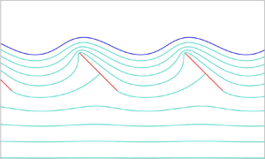
Figure 5(a–c) shows free surface profiles and sub-surface streamlines for flows past periodic rows of hydrofoils at a positive angle of attack of  $-\alpha ={\rm \pi} /4$ and with leading-edge submergence $y_c=0.3$ for various periods $\lambda$. A similar plot for flow past a single foil – i.e. the limiting case of $\lambda \rightarrow \infty$ – at the same angle of attack and with the same leading-edge submergence is shown in figure 6(b) of MJ23. Figure 5(d) shows the free-surface profile and sub-surface streamlines for flow past a periodic row of foils at a negative angle of attack of $-\alpha =-{\rm \pi} /3$. A similar plot for flow past a single foil is shown in figure 6(c) of MJ23. As examples of the corresponding values of the mapping parameters, those that we found for the solution that is shown in figure 5(b) are $q=0.1834$ (to 4 d.p. – we report other values to the same accuracy except where indicated otherwise), $\beta =0.2783$, $\mathrm {arg}\{\zeta _1\}=2.8504$, $\mathrm {arg}\{\zeta _2\}=5.0227$ and $\mathrm {arg}\{\zeta _c\}=2.2096$. For this solution, $\lambda =2$. It appears that as $\lambda$ increases (for a fixed $y_c$), $q$ and $\beta$ increase; for the solution that is shown in figure 5(a) – for which $\lambda =1$ – we found $q=0.0571$ and $\beta =0.0603$, while for that in figure 5(c) – for which $\lambda =8$ – we found $q=0.2666$ and $\beta =0.8199$.
Free-surface profiles (blue) and sub-surface streamlines (turquoise) for flow past a periodic row of hydrofoils (red) for various periods  $\lambda$, angles of attack $-\alpha$ and leading-edge submergences $y_c$: (a) $-\alpha ={\rm \pi} /4$, $y_c=0.3$, $\lambda =1$; (b) $-\alpha$, $y_c$ as per panel (a), $\lambda =2$; (c) $-\alpha$, $y_c$ as per panel (a), $\lambda =4$; (d) $-\alpha =-{\rm \pi} /3$, $y_c=1.2$, $\lambda =3$. For each of panels (a–d), the absolute value of the difference between the values of the associated streamfunction on adjacent streamlines is the same for all pairs of adjacent streamlines. Lengths here and in subsequent figures are normalised on the length of the foils.

Two distinctive features appear in figure 5. First, periodicity requires the value of the streamfunction to be the same on each foil and so there is no net flow between the plates: the separating streamline on a given plate meets the succeeding plate at the stagnation point on its leading face. This is a consequence of the presence of the free surface: in infinite submergence flow, a through-array velocity can be imposed (König Reference König1922; Kawada Reference Kawada1930). Second, the surface speed,  $U_0$, can differ substantially from the speed at depth, $U_\infty$. The circulation around each foil means that the foils act as a row of negative (when the angle of attack is positive) point vortices, or shear layer, causing $U_0$ to exceed $U_\infty$. Similarly, for negative angle of attack, the foil circulation means $U_0< U_\infty$. The circulation is related to the lift and we have, from (4.9),
 \begin{equation} U_0^2 = (1 +C_L/\lambda) U_\infty^2. \end{equation}
The behaviour of the ratio  $U_0/U_\infty$ as a function of submergence $y_c$ thus follows from figure 8. For angle of attack ${\rm \pi} /4$, the ratio increases monotonically and rapidly with $y_c$, achieving its infinite submergence value for $y_c$ of order unity. For angle of attack $-{\rm \pi} /3$, the ratio is approximately constant as a function of $y_c$. It appears (from these plots and others not included here) that for a fixed angle of attack $-\alpha$ (whether positive or negative) and submergence $y_c$, the disturbance to the free surface decreases as the interfoil separation $\lambda$ decreases. This is supported by figure 6 which shows the surface disturbance amplitude, $a$, i.e. the vertical height between a peak and a trough (i.e. ${\rm Im}(z_p-z_t)$ of Appendix A) as a function of $\lambda$. The amplitude is infinite for a single plate ( $\lambda \gg 1$) but decreases rapidly and monotonically as $\lambda$ decreases falling to less than 5 % of the chord length once the foils are separated by less than a chord length.
The surface disturbance amplitude,  $a$, i.e. the vertical height between a peak and a trough, as a function of $\lambda$ for various leading-edge submergences $y_c$ and angles of attack: (a) $-\alpha ={\rm \pi} /4$; (b) $-\alpha =-{\rm \pi} /3$.

Figure 7(a,b) shows more free-surface profiles for flows past rows of hydrofoils with  $-\alpha ={\rm \pi} /4$ and $\lambda =2$, and $-\alpha =-{\rm \pi} /3$ and $\lambda =3$, respectively, for different values of $y_c$. The shapes of these profiles are consistent with those for flows past a single foil, as shown in figure 5 of MJ23. In particular, for any $\lambda >0$, it appears that for a positive angle of attack, solutions exist for all $y_c>0$ and in the limit as $y_c\rightarrow 0$, the free surface ‘shrinks’ onto the foils, while for a negative angle of attack, solutions exist for all $y_c$ greater than some lower bound at which the free surface develops cusps (at $z_c$ and at all other troughs along it; for the solutions shown in figure 7(b), this lower bound is just less than $0.33$). As for the mapping parameters, it is shown in Appendix D.3.1 that for any angle of attack (whether positive or negative), $y_c\rightarrow \infty$ as $q\rightarrow 0$ with $\beta \sim O (q)$. However, it appears that $q\rightarrow 1$ as $y_c$ decreases. In particular, for the solution with $\lambda =2$, $-\alpha ={\rm \pi} /4$ and just $y_c=2$ (not shown in figure 7a), we found $q=0.000567$ and $\beta =0.000837$ (to 6 d.p.), while for the solution shown in figure 7(a) with $y_c=1$, we found $q=0.0135$ and $\beta =0.0201$, and for that with $y_c=0.01$, we found $q=0.9399$ and $\beta =0.9984$.
Free-surface profiles for flow past a periodic row of hydrofoils at various leading-edge submergences,  $y_c$: (a) angle of attack $-\alpha ={\rm \pi} /4$, period $\lambda =2$, $y_c=0.01, 0.05$ and $0.1, 0.2, 0.3,\dots, 1$; (b) $-\alpha =-{\rm \pi} /3$, $\lambda =3$, $y_c=0.33$ and $0.8, 1.0, 1.2, \dots, 2$.

Figure 8(a,b) shows graphs of the lift coefficient  $C_L$ as a function of the leading-edge submergence $y_c$ for various periods $\lambda$ and angles of attack $-\alpha ={\rm \pi} /4$ and $-\alpha ={\rm \pi} /3$, respectively. We computed these by evaluating the expression on the far right-hand side of (4.9). The shapes of these graphs are consistent with similar plots for flows past a single foil shown in figure 7 of MJ23. It appears that for a positive angle of attack, $C_L$ is a positive, monotonic increasing function of $y_c$ that tends to $0$ as $y_c\rightarrow 0$. (The smallest value of $y_c$ for which we have plotted values of $C_L$ in figure 8(a) is $y_c=0.01$.) For both positive and negative angles of attack, $C_L$ tends to a limiting value as $y_c\rightarrow \infty$. A formula for this limit of $C_L$ for flow past a row of foils at an infinite submergence (as a function of $\alpha$ and $\lambda$) is derived in Appendix D.3 – see (D8); values of it are indicated by the dashed lines in figure 8. It appears from figure 8 that $C_L$ approaches this limiting infinite submergence value more rapidly (i.e. for smaller $y_c$) for smaller $\lambda$. In Appendix D.3.1, we show that as $\lambda \rightarrow 0$, this limiting value of $C_L$ (and the limit of $U_0$) tends to infinity for a positive angle of attack and $0$ for a negative angle of attack.
The lift coefficient  $C_L$ as a function of the leading-edge submergence $y_c$ for various periods $\lambda$ and angles of attack $-\alpha$: (a) $-\alpha ={\rm \pi} /4$; (b) $-\alpha =-{\rm \pi} /3$. The dashed lines indicate the limiting values for $C_L$ as $y_c\to \infty$, given by (D8).

To prevent separation and reduce drag, hydrofoils are most likely to be operated at small angles of attack. The relevant physical quantity then becomes the rate of change of  $C_L$ at zero angle of attack, shown in figure 9(a) as a function of submergence $y_c$ for various periods, $\lambda$ (as one would expect, $C_L=0$ at zero angle of attack – see Appendix D.1). The rapid approach with increasing depths to the infinite submergence value for shorter array periods is evident, in particular, at the period of $\lambda =2$, where the infinite submergence value is almost achieved by a submergence of $y_c=0.5$. Figure 9(b) shows graphs of the moment $\mathcal {M}$ of each hydrofoil about its midpoint, as a function of $y_c$, for an angle of attack of $-\alpha ={\rm \pi} /4$ and various $\lambda$. From Blasius's theorem and (3.3) (and recalling that the midpoint of the foil whose leading edge is at the origin is $\mathrm {e}^{\mathrm {i}\alpha }/2$), we have
 \begin{equation} \mathcal{M}={-}\frac{\rho}{2}\mathrm{Re}\left\{\oint_{\mathcal{C}} \left(z-\frac{\mathrm{e}^{\mathrm{i}\alpha}}{2}\right)(w'(z))^2\,\mathrm{d}z\right\} ={-}\frac{\rho}{2}\mathrm{Re}\left\{\oint_{\mathcal{C}_{\zeta}} \left(z(\zeta)-\frac{\mathrm{e}^{\mathrm{i}\alpha}}{2}\right) W'(\zeta)\varOmega(\zeta)\,\mathrm{d}\zeta\right\}, \end{equation}
where  $\mathcal {C}$ and $\mathcal {C}_{\zeta }$ are as in (2.8) and (3.15), respectively, and we integrate around both of them in the anticlockwise direction, and $\rho$ is the density of the fluid (which we set to $1$). Unlike the integral in (4.2) for the force on each foil, we have been unable to evaluate that (with respect to $\zeta$) in (5.2) for $\mathcal {M}$ analytically, and have instead computed it numerically (using the MATLAB routine integral). In the limit as $y_c\rightarrow \infty$, we computed $\mathcal {M}$ using (D10). Again, the rapid approach to the infinite submergence value for shorter array periods is evident.
(a) The rate of change of the lift coefficient  $C_L$ with respect to the angle of attack $-\alpha$ at $\alpha =0$, as a function of the leading edge submergence $y_c$ for various periods $\lambda$. The dashed lines indicate the limiting values as $y_c\to \infty$, obtained from (D8). (b) The moment $\mathcal {M}$ as a function of $y_c$ for $-\alpha ={\rm \pi} /4$ and various $\lambda$. The dashed lines indicate the limiting values as $y_c\to \infty$.

6. Discussion
We have presented an explicit solution for infinite-depth, irrotational, two-dimensional, free-surface, attached flow over a tandem array of inclined flat plates in the limit of infinite Froude number. The flow patterns are described by three quantities, the angle of attack,  $-\alpha$, the depth of submergence, $y_c$, and the horizontal period, $\lambda$, of the array, with the solution parameters determined as the simultaneous roots of five real nonlinear algebraic equations arising from the flow normalisation. This explicit form allows accurate evaluation of various flow quantities.
The minimum computation required to obtain the lift coefficient  $C_L$ and reproduce the examples presented in § 5 consists of choosing $\alpha$, $y_c$ and $\lambda$, and then solving simultaneously the five equations (3.42)–(3.46) (subject also to (3.47)) for the five real numbers $\arg \{\zeta _1\}$, $\arg \{\zeta _2\}$, $q$,
$q$,  $\beta$ and $\arg \{\zeta _c\}$, implementing the functions $P(\zeta,q)$, $K(\zeta,q)$ and $L(\zeta,q)$ using the expressions (3.5), (3.8) and (3.50). The value of $C_L$ is then given by (4.9).
The solutions have two distinct features that do not appear to have been remarked upon elsewhere: unlike the infinite-submergence case where a through-array flow can be imposed, in the finite submergence case here, periodicity and the presence of the free surface mean that there is no net flow between the plates – the separating streamline on a given plate meets the succeeding plate at the stagnation point on its leading face; and the surface speed,  $U_0$, can differ substantially from the speed at depth, $U_\infty$, with the circulation around each foil causing the foils to act as a row of point vortices, or a shear layer, so the speeds are related to the lift coefficient through (5.1), i.e.
 \begin{equation} U_0^2 = (1 +C_L/\lambda) U_\infty^2. \end{equation}
 The most significant approximation here is the assumption of infinite Froude number,  ${\textit{Fr}}$. The results of Semenov & Wu (Reference Semenov and Wu2020) for flow past an isolated cylinder at ${\textit{Fr}}=5$ show that surface waves are absent at sufficiently large submergence and for sufficiently small submergence. This is supported by the comparison in MJ23 of the lift coefficient $C_L$ for an isolated plate and those of Semenov & Wu (Reference Semenov and Wu2020) for ${\textit{Fr}}\geq 5$. The general similarity across all submergences suggests that at these Froude numbers, the presence of surface waves has little effect on lift on isolated obstacles, though, of course, introducing drag. Figure 5 shows that for a given submergence, the free surface disturbance decreases rapidly with decreasing array period $\lambda$. Figures 8 and 9 bear this out, showing that with decreasing $\lambda$, the lift coefficient and force moment approach their infinite submergence values significantly more rapidly. The explicit results here may thus be of relevance at smaller Froude numbers and over a wider range of submergences than those for isolated foils.
The Kutta condition for smoothly detaching flow introduces circulation into the flow. For an isolated obstacle at infinite Froude number, this causes the free surface to diverge logarithmically upwards or downwards, depending on the sign of the circulation, at large distances (Semenov & Wu Reference Semenov and Wu2020, MJ23). The finite separation of foils in the periodic tandem array here means that the vertical extent of any dip or bump in the surface is bounded and the surface cannot diverge vertically to infinity. Such a divergence would still occur in infinite depth flow for a finite tandem array. The extension of this method to finite depth is straightforward although the most direct method increases the connectivity of the pre-image domain and thus requires higher-connectivity prime functions which are less trivial numerically. This analysis will be presented elsewhere.
The solution presented here is valid for arbitrary angles of attack and submergences but is unlikely to be observed at large angles of attack when flows are likely to display separation, cavitation or ventilation and three-dimensional and viscous effects as described in review articles and texts including, for example, Acosta (Reference Acosta1973), Faltinsen (Reference Faltinsen2005) and Molland & Turnock (Reference Molland and Turnock2022), yet the solution does reinforce observations that tandem hydrofoils offer significant lift advantages and shows that free-surface disturbance by an array decreases rapidly with decreasing foil separation.
Acknowledgements
We are grateful to Dr Y. Semenov and two anonymous referees for their helpful comments.
Declaration of interests
The authors report no conflict of interest.
Appendix A. The symmetry of figure 4(b)
Introduce (Kirchhoff Reference Kirchhoff1869; Planck Reference Planck1884),
 \begin{equation} Q(\zeta) =\log(U_0/\varOmega)=\log(U_0/s)+{\rm i}\gamma,\quad \varOmega(\zeta) = U_0\exp({-}Q), \end{equation}
where  $s =|\varOmega |$ and $\gamma =-\arg \varOmega$ are the magnitude and direction (relative to the positive $x$-axis) of the velocity in the $z$-plane. Then $Q$ is holomorphic in the annulus $q<|\zeta |<1$ with boundary conditions
 \begin{equation} {\rm Re}\{Q\} = 0 \quad\text{on}\ |\zeta|=1, \end{equation}
since  $s=U$ there, and on $|\zeta |=q$,
 \begin{equation} {\rm Im}\{Q\}=f(\zeta), \end{equation}
where, since the velocity is at angle  $\alpha$ or $\alpha +{\rm \pi}$ there for positive angle of attack ( $\alpha <0$),
 \begin{equation} f(\zeta)=\begin{cases} \alpha + {\rm \pi}& \text{for } \arg{\zeta} \text{ between } \arg{\zeta_1} \text{ and } \arg{\zeta_3},\\ \alpha & \text{otherwise}. \end{cases} \end{equation}
For negative angle of attack ( $\alpha >0$),
 \begin{equation} f(\zeta)=\begin{cases} \alpha - {\rm \pi}& \text{for } \arg{\zeta} \text{ between } \arg{\zeta_1} \text{ and } \arg{\zeta_2},\\ \alpha & \text{otherwise}. \end{cases} \end{equation}
For positive angle of attack, as in figure 4(b), (A4) shows that  ${\rm Im}\{Q\}$ is even on $|\zeta |=q$ about the point where $\arg \zeta = (\arg \zeta _1+\arg \zeta _3)/2 =\theta _s$ (say). Hence, ${\rm Re}\{Q\}$ on $|\zeta |=q$ is odd about this point. Thus, regarded as a solution in the annulus of Laplace's equation subject to a boundary condition with this symmetry and to (A2), ${\rm Re}\{Q\}$ is odd about the line ${\mathcal {L}}$ given by $\arg \zeta =\theta _s$ and its extension $\arg \zeta =\theta _s\pm {\rm \pi}$. It follows that ${\rm Im}\{Q\}$ is even about ${\mathcal {L}}$. Let $\zeta _a$ and $\zeta _b$ be two points in the annulus located symmetrically about ${\mathcal {L}}$, so $\zeta _b=\exp (2{\rm i} \theta _s)\bar {\zeta }_a$ and $Q(\zeta _a)=-\overline {Q(\zeta _b)}$. Then
 \begin{equation} \varOmega(\zeta_a)\overline{\varOmega(\zeta_b)} = U_0^2\exp[{-}Q(\zeta_a)-\overline{Q(\zeta_b)}] =U_0^2. \end{equation}
The modulus of (A6) gives  $|\varOmega (\zeta _a)||\varOmega (\zeta _b)| = U_0^2$. This is the symmetry visible in figure 4(b) and also figure 4(b) of MJ23 (where $U_0=U_\infty =U)$. In particular, along the straight line $\arg \zeta =\theta _s, \theta _s\pm {\rm \pi}$, $|\varOmega (\zeta )|=U_0$, the free-surface velocity. Also, the pole at $\zeta _1$ and zero at $\zeta _3$ combine so that $|\varOmega (\zeta _1)||\varOmega (\zeta _3)| = U_0^2$. The argument of (A6) gives $\arg \varOmega (\zeta _b)=-\arg \varOmega (\zeta _a)$. One consequence of this is that the preimage point, $\zeta _p$, of the peak, the highest point on the free surface, $z_p$, and the preimage point, $\zeta _t$, of the trough, the lowest point on the free surface, $z_t$, can be expressed in terms of $\zeta _1$ and $\zeta _2$ by noting that in each wavelength, the velocity on the surface is horizontal only at at $z_p$ and $z_t$, and so $\zeta _p$ and $\zeta _t$ are symmetric about ${\mathcal {L}}$, giving $\arg \zeta _p+\arg \zeta _t = \arg \zeta _1-\arg \zeta _2+{\rm \pi}$.
The same discussion applied to (A5) shows that for negative angles of attack, the same relations hold with however the line  ${\mathcal {L}}$ becoming the line $\arg \zeta = (\arg \zeta _1+\arg \zeta _2)/2$ and its extension, so $\zeta _b=\exp [{\rm i}(\arg \zeta _1+\arg \zeta _2)]\bar {\zeta }_a$.
Appendix B. Determining $\beta _0,\ldots,\beta _5$

First, recalling (3.20) and (3.27), as well as (3.8), one finds by comparing the residues of the right-hand sides of (3.34) and (3.36) at  $\zeta =-\mathrm {i}\beta$ that
 \begin{equation} \beta_2=\frac{\mathrm{i}\lambda}{2{\rm \pi}}. \end{equation}
Equation (B1) is to be expected, given our assumption of (3.1).
Next, by using both of (3.26a,b) (see MJ23 for further details – cf. (3.30) and (3.32) of the latter), one can show that
 \begin{equation} \varOmega(\zeta)=\frac{U_0^2}{\bar{\varOmega}(1/\zeta)},\quad \varOmega(q^2\zeta)=\frac{U_0^2\mathrm{e}^{-2\mathrm{i}\alpha}}{\varOmega(\zeta)}, \end{equation}
where we define  $\bar {\varOmega }(\zeta )=\overline {\varOmega (\bar {\zeta })}$. It follows from (3.27) and (B2a,b) that
 \begin{equation} \varOmega(-\mathrm{i}/\beta)=\frac{U_0^2}{U_{\infty}},\quad \varOmega(-\mathrm{i}q^2\beta)=\frac{U_0^2\mathrm{e}^{-2\mathrm{i}\alpha}}{U_{\infty}},\quad \varOmega(-\mathrm{i}q^2/\beta)=U_{\infty}\mathrm{e}^{-2\mathrm{i}\alpha}. \end{equation}
Then, using (3.20) and (3.8) now with (B3a–c), one finds by comparing the residues of the right-hand sides of (3.34) and (3.36) at  $\zeta =-\mathrm {i}/\beta, -\mathrm {i}q^2\beta$ and $-\mathrm {i}q^2/\beta$, respectively, that
 \begin{equation} \beta_3={-}\frac{\mathrm{i}\lambda}{2{\rm \pi}}\left(\frac{U_{\infty}}{U_0}\right)^2,\quad \beta_4=\frac{\mathrm{i}\lambda}{2{\rm \pi}}\left(\frac{U_{\infty}\,\mathrm{e}^{\mathrm{i}\alpha}}{U_0}\right)^2,\quad \beta_5={-}\frac{\mathrm{i}\lambda\,\mathrm{e}^{2\mathrm{i}\alpha}}{2{\rm \pi}}. \end{equation}
 Next, for  $H(\zeta )$ as given by (3.36) to satisfy (3.35), it follows from (3.9a) that
 \begin{equation} \beta_1={-}(\beta_2+\beta_3+\beta_4+\beta_5), \end{equation}
and hence from (B1) and (B4a–c) that
 \begin{equation} \beta_1=\frac{\mathrm{i}\lambda}{2{\rm \pi}}(\mathrm{e}^{2\mathrm{i}\alpha}-1) \left(1-\left(\frac{U_{\infty}}{U_0}\right)^2\right). \end{equation}
 Finally, it follows from (3.34) and the properties of  $W'(\zeta )$ and $\varOmega (\zeta )$ that $H(\zeta )$ has a (simple) zero at $\zeta =\zeta _1$. Then, setting $\zeta =\zeta _1$ in (3.36) and using the fact that $K(q^2,q^2)=0$ (which one can deduce by using both equations in (3.9a,b)) as well as (B1) and (B4a–c), it follows that
 \begin{align} \beta_0 &={-}\frac{\mathrm{i}\lambda}{2{\rm \pi}}\left(K(\mathrm{i}\zeta_1/\beta,q^2)- \left(\frac{U_{\infty}}{U_0}\right)^2 K(\mathrm{i}\beta\zeta_1,q^2)\right. \nonumber\\ &\quad \left.+\left(\frac{U_{\infty}\,\mathrm{e}^{\mathrm{i}\alpha}}{U_0}\right)^2 K(\mathrm{i}q^2\zeta_1/\beta,q^2)-\mathrm{e}^{2\mathrm{i}\alpha} K(\mathrm{i}q^2\beta\zeta_1,q^2)\right). \end{align}
Appendix C. Determining the sum $\gamma _0+\gamma _1$

First, we note that it follows from (4.3) and the properties of  $W'(\zeta )$ and $\varOmega (\zeta )$ that $\eta (\zeta )$ has a (simple) zero at $\zeta =1/\overline {\zeta _1}$. Then, setting $\zeta =1/\overline {\zeta _1}$ in (4.5), and using the fact that $K(1/q^2,q^2)=1$ (which follows from the fact that $K(q^2,q^2)=0$ – see just after (B6) – and (3.9a)) and recalling that $1/\overline {\zeta _1}=\zeta _1/q^2$ as well as (3.9a), it follows that
 \begin{align} & \gamma_0+\gamma_1+\gamma_2+\gamma_3+\gamma_2 K(\mathrm{i}q^2\zeta_1/\beta,q^2) +\gamma_3 K(\mathrm{i}q^2\beta\zeta_1,q^2)+\gamma_4 K(\mathrm{i}\zeta_1/\beta,q^2) \nonumber\\ &\quad +\gamma_5 K(\mathrm{i}\beta\zeta_1,q^2)=0. \end{align}
Next, one can determine the constants  $\gamma _2,\ldots \gamma _5$ in a similar manner to how we determined the constants $\beta _2,\ldots \beta _5$ in Appendix B, i.e. by comparing the residues of the right-hand sides of (4.3) and (4.5) at $\zeta =-\mathrm {i}\beta$, $-\mathrm {i}/\beta$, $-\mathrm {i}\beta /q^2$ and $\zeta =-\mathrm {i}/(q^2\beta )$; one finds that
 \begin{equation} \gamma_2=\frac{\mathrm{i}\lambda U_{\infty}^2}{2{\rm \pi}},\quad \gamma_3={-}\frac{\mathrm{i}\lambda U_0^2}{2{\rm \pi}},\quad \gamma_4=\frac{\mathrm{i}\lambda}{2{\rm \pi}}(U_0\,\mathrm{e}^{-\mathrm{i}\alpha})^2,\quad \gamma_5={-}\frac{\mathrm{i}\lambda}{2{\rm \pi}}(U_{\infty}\,\mathrm{e}^{-\mathrm{i}\alpha})^2. \end{equation}
Then, substituting for  $\gamma _2,\ldots,\gamma _5$ in (C1) with (C2a–d), and also recalling (B7) and the requirement (3.39), one finds that
 \begin{equation} \gamma_0+\gamma_1=\frac{\mathrm{i}\lambda}{2{\rm \pi}}(U_0^2-U_{\infty}^2). \end{equation}
Appendix D. Limiting cases
D.1. Horizontal hydrofoils
We have thus far assumed that  $\zeta _1\neq -\overline {\zeta _2}$ (see the first paragraph of § 3.3). However, let us now consider the limit of our results as $\zeta _1\rightarrow -\overline {\zeta _2}$. In this limit, it follows from (3.29) and (3.30) that $\varOmega (\zeta )=U_{\infty }$ for all $\zeta$, and hence that $w'(z)=U_{\infty }$ for all $z$, and so the hydrofoils must be horizontal. Indeed, in this limit, it follows from (3.43) that $\mathrm {e}^{2\mathrm {i}\alpha }=1$. Furthermore, by also using the fact that now $U_0=U_{\infty }$, one can show that (B1), (B4a–c) and (B6) now give $\beta _1=0$ and $\beta _2=-\beta _3=\beta _4=-\beta _5=\mathrm {i}\lambda /(2{\rm \pi} )$, and hence (by also using (3.11)) that our expression (3.37) for $z(\zeta )$ now reduces to
 \begin{equation} z(\zeta)=\frac{\mathrm{i}\lambda}{2{\rm \pi}}\log\left(\frac{P(\mathrm{i}\zeta/ \beta,q)}{P(\mathrm{i}\beta\zeta,q)}\right)+c. \end{equation}
By using the properties of  $P(\zeta,q)$, one can show that $z(\zeta )$ as given by (D1) maps $C_1$ onto a periodic row of horizontal, finite-length straight slits with period $\lambda$. (In particular, one can show that these slits are horizontal by considering $\overline {z(\zeta )}$ and using the fact that $\bar {\zeta }=q^2/\zeta$ for $\zeta \in C_1$.) Similarly, one can also check that it maps $C_0$ onto a horizontal line that extends to infinity in both directions – this is the free surface in this case. We also mention that, in this case, it follows from (B7) (by using (3.12)) that
 \begin{equation} \beta_0={-}\frac{\mathrm{i}\lambda}{2{\rm \pi}} (K(\mathrm{i}\zeta_1/\beta,q)-K(\mathrm{i}\beta\zeta_1,q)). \end{equation}
Then, by comparing the form on the right-hand side of (D2) with that of  $z'(\zeta _1)$ that follows from (D1) (recalling (3.7)), and recalling that $z'(\zeta _1)=0$, one can show that $\beta _0=0$ and thus the single-valuedness condition (3.39) is now satisfied automatically. Similarly, by using the fact that $z'(\zeta _2)=0$, one can show that the circulation, $\varGamma$, around each hydrofoil, as given by (3.21), is also zero in this case. Furthermore, it follows from (4.8) (and the fact that now $U_0=U_{\infty }$) that, in this case, the fluid exerts no force on the hydrofoils.
D.2. Near-vertical hydrofoils
We have also thus far assumed that  $-\overline {\zeta _2}\neq \zeta _2$, or equivalently, that $\zeta _2\neq \pm \mathrm {i}q$ (see just after (3.22)). However, let us now consider the limit of our results as $\zeta _2\rightarrow \pm \mathrm {i}q$ whilst $\zeta _1\rightarrow \mp \mathrm {i}q$. In both of these limits, it follows from (3.43) that $\mathrm {e}^{2\mathrm {i}\alpha }\rightarrow -1$, and so $\alpha \rightarrow {\rm \pi}/2$ or $-{\rm \pi} /2$, i.e. the hydrofoils are approaching vertical. As explained in §2, we will not consider rows of strictly vertical hydrofoils, so we refrain from providing further details of this limiting case here other than to mention the following. As one might expect, our solutions for rows of near-vertical foils as $\alpha \rightarrow {\rm \pi}/2$ are qualitatively very different from those as $\alpha \rightarrow -{\rm \pi} /2$, as illustrated by figure 10. Also, it is evident from (3.25) that in this limit, $\zeta _3\rightarrow \zeta _2$ and hence $z_3\rightarrow z_2$, i.e. the stagnation points of the flow approach the trailing endpoints of the hydrofoils. Finally, we mention that for the solution illustrated in figure 10(a), we found $\arg \{\zeta _1\}=1.5851$, $\arg \{\zeta _2\}=-1.5642$, while for that in figure 10(b), $\arg \{\zeta _1\}=-1.5762$, $\arg \{\zeta _2\}=1.5538$.
Free-surface profiles (blue) and sub-surface streamlines (turquoise) for flow past a periodic row of near-vertical hydrofoils (red) with period  $\lambda =4$, angles of attack $-\alpha$ and leading-edge submergences $y_c$: (a) $-\alpha =({\rm \pi} /2)-0.01$, $y_c=0.3$; (b) $-\alpha =-({\rm \pi} /2)+0.01$, $y_c=1.3$.

D.3. Hydrofoils at infinite submergence
We now consider the limit of our results as  $q\rightarrow 0$ with $\beta \sim O (q)$ (so $q/\beta \sim O (1)$). First, it is convenient to introduce a new parametrising variable defined by $\xi =q/\zeta$. The image of $D_{\zeta }$ in the $\xi$-plane is also a concentric annulus $D_{\xi }$, say, that is bounded by circles that are centred on the origin and of radius $1$ and $q$, but now, under the map $z(q/\xi )=\hat {z}(\xi )$, say, it is the outer boundary circle of $D_{\xi }$ that maps onto the hydrofoils in the $z$-plane, while the inner boundary circle maps onto the free surface. Also, the image of $\zeta _{\infty }$ in the $\xi$-plane is the point $\xi _{\infty }=\mathrm {i}q/\beta$, while for $j=1,2$, the image of $\zeta _j$ is the point $\xi _j=q/\zeta _j$; so, under $\hat {z}(\xi )$, $\xi _{\infty }$ and $\xi _j$ map onto the point at infinity and $z_j$ in the $z$-plane, respectively. We point out that $q<\mathrm {Im}\{\xi _{\infty }\}<1$ (recall that $q<\beta <1$).
In the limit as  $q\rightarrow 0$ with $\beta \sim O (q)$, evidently $D_{\xi }$ reduces to the unit disc while $\xi _{\infty }$ remains of order $1$. Furthermore, consider the form for $\hat {z}(\xi )$ that follows from (3.37) with $\zeta =q/\xi$ and also $c$ as given by (3.41); noting that for $\xi \in D_{\xi }$, we have $q<|\xi |<1$ and hence $q^2<|q\overline {\zeta _1}/\xi |,|q\beta /\xi |< q$ and $1<|q/(\beta \xi )|<1/q$, one may deduce from (3.5) that in this limit, $P(q\overline {\zeta _1}/\xi,q^2)$, $P(\mathrm {i}q\beta /\xi,q^2)$ and $P(\mathrm {i}q^3/(\beta \xi ),q^2)$ all tend to $1$, while $P(\mathrm {i}q/(\beta \xi ),q^2)\rightarrow (1-(\mathrm {i}q/\beta )\xi ^{-1})=(1-\xi _{\infty }\xi ^{-1})$ and $P(\mathrm {i}q^3\beta /\xi,q^2)\rightarrow (1+\xi _{\infty }\xi )$, and hence that this form for $\hat {z}(\xi )$ reduces to
 \begin{equation} \hat{z}(\xi)=\frac{\mathrm{i}\lambda}{2{\rm \pi}} \left(\log\left(\frac{\xi_1}{\xi}\left(\frac{\xi-\xi_{\infty}}{\xi_1-\xi_{\infty}}\right)\right) -\mathrm{e}^{2\mathrm{i}\alpha} \log\left(\frac{\xi-\overline{\xi_{\infty}}^{{-}1}}{\xi_1-\overline{\xi_{\infty}}^{{-}1}}\right)\right). \end{equation}
It is evident that  $\hat {z}(\xi )$ as given by (D3) has branch points at $\xi =0$, $\xi _{\infty }$, $\overline {\xi _{\infty }}^{-1}$ and infinity. Furthermore, one may deduce that this limiting form for $\hat {z}(\xi )$ maps the unit $\xi$-circle onto a periodic row of hydrofoils (modelled by finite-length slits) with period $\lambda$, an angle of attack of either $-\alpha$ or $-\alpha +{\rm \pi}$ (as follows by considering $\overline {\hat {z}(\xi )}$ and using the fact that $\bar {\xi }=1/\xi$ when $|\xi |=1$) and $z_1=0$, and maps the interior of the unit $\xi$-disc onto the whole of the region exterior to these hydrofoils. Thus, the hydrofoils in this limiting case are at an infinite depth. Their angle of attack will be fixed at $-\alpha$ (rather than $-\alpha +{\rm \pi}$) provided one correctly identifies $\xi _1$ and $\xi _2$. These are now functions of $\xi _{\infty }$ and are given by the two roots of a quadratic equation that arises from setting $\hat {z}'(\xi )$ (as given by the derivative of the right-hand side of (D3)) equal to $0$; these roots are
 \begin{equation} \xi_{{\pm}}=\tfrac{1}{2} \left(\xi_{\infty}(1+\mathrm{e}^{-2\mathrm{i}\alpha})\pm \sqrt{\xi_{\infty}^2 (1+\mathrm{e}^{-2\mathrm{i}\alpha})^2+4\mathrm{e}^{-2\mathrm{i}\alpha}}\right). \end{equation}
One may distinguish which of  $\xi _{\pm }$ is $\xi _1$ and which is $\xi _2$ by noting that for small $\varepsilon >0$, we have $\hat {z}(\mathrm {e}^{\mathrm {i}\varepsilon }\xi _j)=\hat {z}(\xi _j)-((\varepsilon \xi _j)^2/2) \hat {z}''(\xi _j)+ O (\varepsilon ^3)$ for $j=1,2$, so we should have (modulo $2{\rm \pi}$)
 \begin{equation} \arg\{\xi_j^2\hat{z}''(\xi_j)\}=\begin{cases} \alpha+{\rm \pi} & \mbox{for } j=1,\\ \alpha & \mbox{for } j=2. \end{cases} \end{equation}
However, first we determine  $\xi _{\infty }$. We do so as the solution of the equation
 \begin{equation} \frac{\lambda}{2{\rm \pi}} \left|\log\left(\frac{\xi_+}{\xi_-}\left(\frac{\xi_--\xi_{\infty}}{\xi_+-\xi_{\infty}}\right)\right) -\mathrm{e}^{2\mathrm{i}\alpha}\log \left(\frac{\xi_--\overline{\xi_{\infty}}^{{-}1}}{\xi_+-\overline{\xi_{\infty}}^{{-}1}}\right)\right|=1, \end{equation}
with  $\xi _{\pm }$ replaced as per (D4). Evidently, (D6) is equivalent to the equation $|\hat {z}(\xi _2)|=1$ which fixes $|z_2|=1$, and defines the same equation for $\xi _{\infty }$ if $\xi _+$ and $\xi _-$ are swapped. We solved (D6) for $\xi _{\infty }$ numerically (using fsolve in MATLAB). We then computed $\xi _{\pm }$ using (D4), and then determined which of these was $\xi _1$ and which was $\xi _2$ by evaluating $\arg \{\xi _{\pm }^2\hat {z}''(\xi _{\pm })\}$ and using (D5). This completes the determination of our parametrisation in this limiting case. We point out that one can also show that the limiting forms of the conditions (3.43) and (3.44) are satisfied automatically in this case.
Now, also in this limit, by using arguments similar to those that lead to (D3), one can show that (3.31) reduces to
 \begin{equation} U_0=U_{\infty}\left|\frac{\xi_{\infty}-\xi_1}{\xi_{\infty}-\xi_2}\right|, \end{equation}
and hence that (4.9) reduces to
 \begin{equation} C_L=\lambda\left(\left|\frac{\xi_{\infty}-\xi_1}{\xi_{\infty}-\xi_2}\right|^2-1\right). \end{equation}
Similarly, one can show that the form for  $\hat {\varOmega }(\xi )=\varOmega (q/\xi )$ that follows from (3.29) reduces to
 \begin{equation} \hat{\varOmega}(\xi)=U_{\infty} \left(\frac{\xi_{\infty}-\xi_1}{\xi_{\infty}+\overline{\xi_2}}\right) \left(\frac{\xi+\overline{\xi_2}}{\xi-\xi_1}\right). \end{equation}
Then, one can compute the moment  $\mathcal {M}$ in this limit from
 \begin{equation} \mathcal{M}={-}\frac{\rho}{2}\mathrm{Re}\left\{\oint_{\mathcal{C}_{\xi}} \left(\hat{z}(\xi)-\frac{\mathrm{e}^{\mathrm{i}\alpha}}{2}\right) \hat{z}'(\xi)(\hat{\varOmega}(\xi))^2\,\mathrm{d}\xi\right\}, \end{equation}
which follows from (5.2), where we can take  $\mathcal {C}_{\xi }$ to be a circle centred on the origin, of any radius between $\mathrm {Im}\{\xi _{\infty }\}$ and 1 (so that it lies in $D_{\xi }$ and contains $\xi _{\infty }$ in its interior), and we integrate around $\mathcal {C}_{\xi }$ in the clockwise direction.
D.3.1. Vanishing period ($\lambda \rightarrow 0$)

As a special case of the above, let us now consider a row of hydrofoils at an infinite depth with  $\lambda \rightarrow 0$ and, in particular, consider $C_L$ (as given by (D8)) in this limit. In this case, one may deduce from (D3) (or (D6)) that to satisfy the condition $|\hat {z}(\xi _2)|=1$, $\xi _{\infty }$ and one of $\xi _1$ and $\xi _2$ must tend to $\mathrm {i}$ (recall that $\xi _{\infty }$ is purely imaginary with $0<\mathrm {Im}\{\xi _{\infty }\}<1$ (as $q\rightarrow 0$) and $\xi _1$ and $\xi _2$ lie on the unit $\xi$-circle). To determine which of $\xi _1$ and $\xi _2$ it is to which $\xi _{\infty }$ tends, note first that it is evident from (D4) that if $\xi _{\infty }\rightarrow \mathrm {i}$, then $\xi _+\rightarrow \mathrm {i}$, while $\xi _-\rightarrow \mathrm {i}\exp ({-2\mathrm {i}\alpha })$; so $\xi _{\infty }\rightarrow \xi _+$. Next, by substituting $\xi _{\infty }=(1-\delta )\mathrm {i}$ for small $\delta >0$ into the forms for $\xi _+$ and $\hat {z}''(\xi _+)$ that are given by (D4) and (D3), one finds (after performing some lengthy but elementary expansions) that
 \begin{equation} \xi_+^2\hat{z}''(\xi_+)={-}\frac{\lambda}{{\rm \pi}\delta^2}(\sin^3\alpha)\, \mathrm{e}^{\mathrm{i}\alpha}+ O (\lambda). \end{equation}
Then, recalling (D5), one may deduce from (D11) and the above that as  $\lambda \rightarrow 0$ with $-{\rm \pi} /2<\alpha <0$, so $\xi _{\infty }\rightarrow \xi _2$. More precisely, as follows from (D6), $|\xi _{\infty }-\xi _2|$ must tend to zero like $\exp ({-1/\lambda })$ in this limit. It then follows from (D8) that (for a row of foils at an infinite depth) as $\lambda \rightarrow 0$ with $-{\rm \pi} /2<\alpha <0$, so $C_L\rightarrow \infty$. (It follows from (D7) that $U_0\rightarrow \infty$ as well, in this limit.) However, one may deduce that as $\lambda \rightarrow 0$ with $0<\alpha <{\rm \pi} /2$, so $\xi _{\infty }\rightarrow \xi _1$ and hence $C_L\rightarrow 0$ (and $U_0\rightarrow 0$).


 Open access

