


Introduction
The enhancement of cell throughput is a key requirement in recent mobile communications, such as 5G or later. Multiple-input multiple-output (MIMO) techniques, using a millimeter-wave (mmWave) band and a sub-terahertz (THz) band, and new modulation scheme are important to enhance the cell throughput significantly. Spatial-division multiplexing (SDM) is one of the MIMO techniques that can multiply many layers. The benefits of using mmWave and sub-THz are wide available frequency range, whereas its difficulties are varying propagation channels more sensitively than in sub-6 GHz. The modulation technique for 4G and 5G is orthogonal frequency-division multiplexing (OFDM). Although OFDM has high-spectral efficiency and good robustness in multi-path fading, inter-carrier interference due to the Doppler effect of time-varying channels degrades OFDM performance for mobility environments. Especially, Doppler effect in mmWave and sub-THz is larger than that in sub-6 GHz. To suppress the degradation, OFDM system allocates reference signals (RS) more frequently and needs to calculate SDM weight matrixes for each OFDM symbol. However, increasing RS allocations decreases spectral efficiency and increases computational complexity for weight calculation drastically.
Orthogonal time-frequency space (OTFS) is suggested to tackle the time-varying channels [Reference Hadani, Rakib, Tsatsanis, Monk, Goldsmith, Molisch and Calderbank1]. OFDM multiplexes information symbols in the time-frequency (TF) domain, whereas OTFS multiplexes them in the delay-Doppler (DD) domain. Because the OTFS modulation spreads each element in the DD grid into the TF domain entirely, all OTFS elements experience the same and nearly constant propagation channel. Using simulation, previous works report that OTFS has a higher bit rate than OFDM for high-mobility environments [Reference Hadani, Rakib, Tsatsanis, Monk, Goldsmith, Molisch and Calderbank1–Reference Shen, Dai, An, Fan and Heath3]. Additionally, in the sub-THz band, direction-based beam-forming will be used as SDM to enhance cell throughput because propagation channels are too sensitive to use null steering method such as zero-forcing (ZF) and minimum mean square error. The direction-based beam-forming utilizes user equipment (UE) positions and velocities to predict the near future UE directions. OTFS distinguishes UEs in the DD domain, and thus OTFS has the possibility to estimate the UE positions and velocities.
We investigate the robustness of OTFS modulation in the Doppler environment with over-the-air (OTA) experiments using a 28 GHz multi-user distributed MIMO (D-MIMO) testbed. D-MIMO is one of the techniques to maximize the SDM performance by using geometrically distant multiple number of antennas [Reference Tawa, Kuwabara, Maruta and Kaneko4, Reference Sezgin, Dahlgren, Eriksson, Coldrey, Larsson, Gustavsson and Fager5]. This paper describes the practical OTFS channel estimation and channel quality with simultaneous multiple user connections for mobility environments.
An earlier version of this paper was presented at the 2021 51st European Microwave Conference and was published in its proceedings [Reference Tawa, Kuwabara, Maruta and Kaneko6].
Signal processing
OTFS modulation
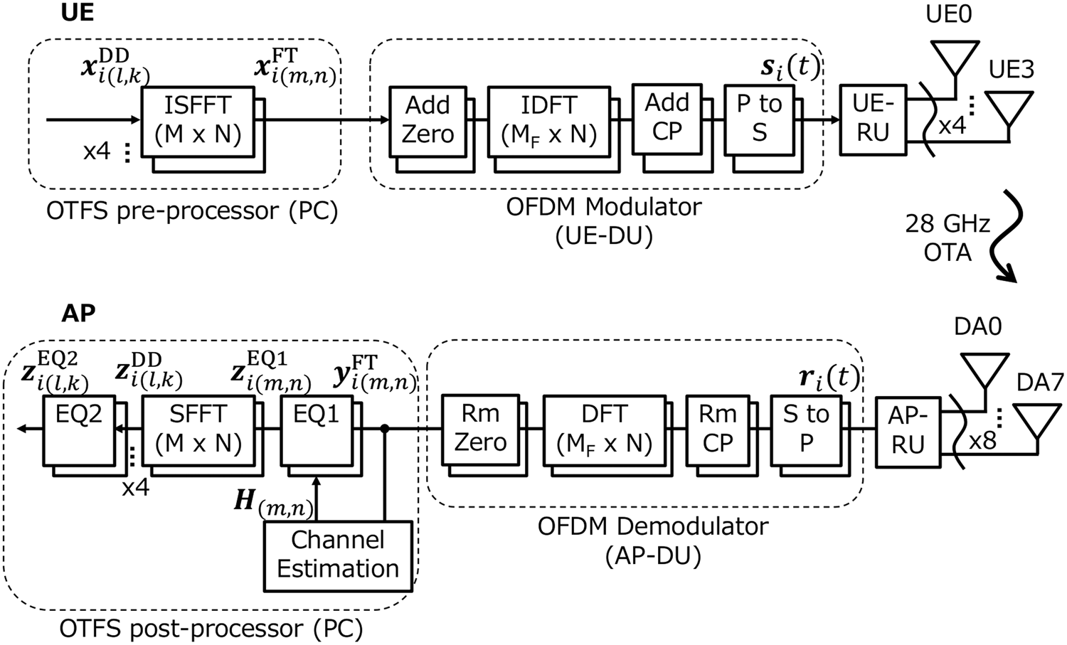
Figure 1 shows the OTFS signal processing diagram. An OTFS pre-processor on a personal computer (PC) generates a multi-user transmitted (TX) signal ${\bf x}_{i( {l, k} ) }^{{\rm DD}} \in {\rm {\mathbb C}}^{U \times 1}$ , where U = 1, 2, or 4 is the number of UEs, allocated in the DD domain with a delay domain index l = 0, 1, …, M − 1 and a Doppler domain index k = 0, 1, …, N − 1. The values of M and N are 1200 and 14, respectively. The OTFS signal ${\bf x}_{i( {l, k} ) }^{{\rm DD}}$
 is an element in subframe i, where i = 0, 1, …, 9, and an OTFS frame has 10 OTFS subframes. The OTFS pre-processor converts ${\bf x}_{i( {l, k} ) }^{{\rm DD}}$
 to a TF-domain signal ${\bf x}_{i( {m, n} ) }^{{\rm TF}} \in {\rm {\mathbb C}}^{U \times 1}$
 , where m = 0, 1, …, M − 1 is a frequency domain index and k = 0, 1, …, N − 1 is a time-domain index, with the inverse symplectic finite Fourier transform (SFFT) [Reference Hadani, Rakib, Tsatsanis, Monk, Goldsmith, Molisch and Calderbank1–Reference Shen, Dai, An, Fan and Heath3]. A distributed unit (DU) for UE, called UE-DU, generates a time-domain digital signal si(t) ∈ ℂU×1, where t is the time, by modulating the TF-domain signal ${\bf x}_{i( {m, n} ) }^{{\rm TF}}$
 with the OFDM modulation. The numerology of the OFDM modulation is based on the specifications of the 3GPP TS 36.211 format [7] except for subcarrier spacing and signal bandwidth, which use 60 kHz and 80 MHz, respectively. A radio unit (RU) for UE, called UE-RU, converts the time-domain digital signal si(t) to an analog signal and then radiates it from UE antennas.
Block diagram of OTFS signal processing.
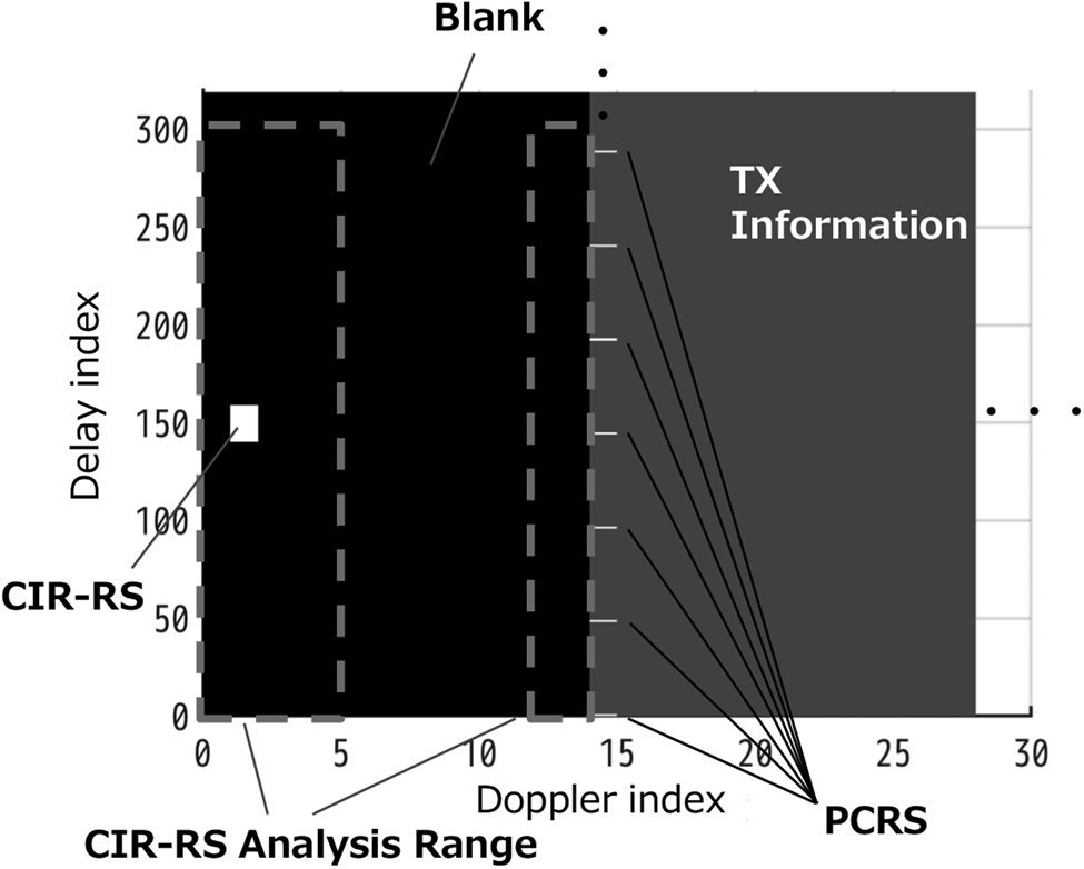
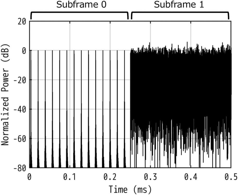
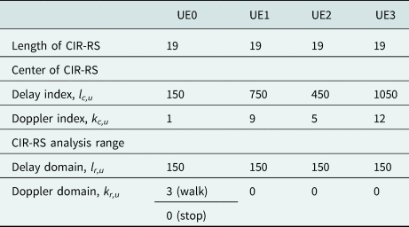
Subframe 0 has only RSs to estimate a channel impulse response (CIR), which is called CIR-RS. CIR-RS uses the root Zadoff-chu sequence with a length of 19 as defined in 3GPP TS 36.211 [7] and is allocated to the DD-domain grids as shown in Fig. 2. Table 1 shows delay indexes l c,u and Doppler indexes k c,u for the CIR-RS center locations of four UEs, UE0–UE3. The other grids in subframe 0 are blank. Subframes 1–9 have quadrature phase shift keying (QPSK) TX information and phase compensation reference signals (PCRSs). PCRS for the u-th UE is a QPSK sequence and is allocated to ${\bf x}_{i( {l_p, 0} ) }^{{\rm DD}}$ , where l p = 48v + u, v = 0, 1, …, 24, and u = 0, 1, 2, 3, as shown in Fig. 2. PCRS and CIR-RS locations are different for each UE to prevent contamination of the RSs between UEs. The amplitude of CIR-RS is 17 dB larger than those of the TX information sequence and PCRS to equalize the peak power of the time-domain signal si(t) between subframe 0 and the other subframes as shown in Fig. 3.
OTFS signal allocation for UE0 from subframe 0 to subframe 1.
Time-domain OTFS waveform of UE0.
Numerology for CIR-RS
OTFS demodulation
A DU for access point (AP), called AP-DU, generates a TF-domain OTFS signal ${\bf y}_{i( {m, n} ) }^{{\rm TF}} \in {\rm {\mathbb C}}^{D \times 1}$ , where D = 8 is the number of distributed antennas (DAs), from the time-domain signal ri(t) ∈ ℂD×1 received by an RU for AP (AP-RU) with the OFDM demodulation.
The propagation channels are estimated by using subframe 0 having CIR-RS. First, the channel estimator in the OTFS post-processor on a PC converts the TF-domain subframe ${\bf y}_{0( {m, n} ) }^{{\rm TF}}$ to the DD-domain subframe ${\bf y}_{0( {l, k} ) }^{{\rm DD}} \in {\rm {\mathbb C}}^{D \times 1}$
 with SFFT, and then extracts CIR-RS from ${\bf y}_{0( {l, k} ) }^{{\rm DD}}$
 . The extracted signal ${\bf g}_{u( {l, k} ) }^{{\rm DD}} \in {\rm {\mathbb C}}^{D \times 1}$
 for the u-th UE is expressed as

where l r,u and k r,u are the CIR-RS analysis ranges of delay domain and Doppler domain, respectively, as shown in Table 1. The CIR-RS analysis range is larger than the CIR-RS allocation range because CIR-RS is distributed by delay and Doppler effects. When the Doppler indexes of CIR-RS analysis range are over subframe 0, the indexes are folded in subframe 0 as shown in Fig. 2. The channel estimator converts the extracted signal ${\bf g}_{u( {l, k} ) }^{{\rm DD}}$ to the TF-domain signal ${\bf g}_{u( {m, n} ) }^{{\rm TF}} \in {\rm {\mathbb C}}^{D \times 1}$
 with inverse SFFT and calculates the propagation channel of the u-th UE, hu(m,n), as
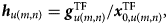
where $x_{0, u( {m, n} ) }^{{\rm TF}}$ is the TF-domain TX signal of the u-th UE in ${\bf x}_{0( {m, n} ) }^{{\rm TF}}$
 . The channel estimator obtains the channel matrix H(m,n) = [h0(m,n), h1(m,n), …, hU−1(m,n)].
The first equalizer (EQ1) performs equalization in the TF domain. The equalized OTFS signal, ${\bf z}_{i( {m, n} ) }^{{\rm EQ1}} \in {\rm {\mathbb C}}^{U \times 1}$ , is calculated as

where W(m,n) ∈ ℂU×D is the equalization weight calculated from the channel matrix H(m,n) by ZF. Subsequently, the OTFS post-processor converts the equalized signal ${\bf z}_{i( {m, n} ) }^{{\rm EQ1}}$ to the DD-domain signal ${\bf z}_{i( {l, k} ) }^{{\rm DD}} \in {\rm {\mathbb C}}^{U \times 1}$
 with SFFT.
The second equalizer (EQ2) corrects the DD-domain signal as follows:

where

The symbols ${\odot}$ and ø denote the Hadamard product and division, respectively. The correction parameters ${\bf c}_{i( {l\notin l_p, k} ) }$
 in the delay indexes without PCRSs are linearly interpolated by using the correction parameters ${\bf c}_{i( {l\in l_p, k} ) }$
 in the delay indexes having PCRSs.
Mathematical analysis of OTFS Doppler effect
This section analyses OTFS signals under Doppler effect and mathematically confirms our demodulator corrects the effect. In this section, for simplicity, the number of UEs is 1, the number of DAs is 1, and the modulation in UE-DU omits adding cyclic prefix. The OTFS pre-processor calculates the TF-domain signal with inverse SFFT as follows:

UE-DU pads zero to the TF-domain signal on the basis of the 3GPP specification [7]. Subsequently, the zero-padded TF-domain signal, $x{\rm ^{\prime}}_{i( {m{\rm^{\prime}}, q} ) }^{{\rm TF}}$ , is converted to the parallel time-domain signal with inverse discrete Fourier transform (DFT) as

where p = 0, 1, …, M F − 1 is a time sample number, M F is 2048, q = 0, 1, …, N − 1 is an OTFS symbol number, and m ʹ = 0, 1, …, M F − 1 is a zero-padded frequency index. The orthogonality between DFT for l in (6) and inverse DFT for m′ in (7) except for when l = Mp/M F is approximated in (7). The time-domain signal s i(t) is generated by parallel-to-serial conversion of s i(p,q). In subframe 0, CIR-RS is simplified to pulse shape signal, and the transmission DD-domain signal is expressed as

Substituting (8) into (6) and (7) gives the TF-domain signal:

and the parallel time-domain signal:

The received (RX) signal radiated from a moving UE is affected by Doppler effect, and its carrier frequency is shifted. The RX signal after serial-to-parallel conversion is expressed as

where h is a propagation coefficient, fo is a frequency shift caused by the Doppler effect, and ts is a sampling interval. t s(M FNi + M FMq + p) in (11) means the received time from the frame beginning. This analysis assumes constant propagation coefficient and omits additive white Gaussian noise (AWGN). AP-DU converts the RX signal with DFT as follows:
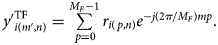
Subsequently, AP-DU suppresses zero padded in UE-DU and generates the TF-domain signal $y_{i( {m, n} ) }^{{\rm TF}}$ . The TF-domain signal in subframe 0 is expressed as
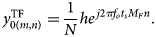
The channel estimator estimates the propagation channel using $y_{0( {m, n} ) }^{{\rm TF}}$ . Although the channel estimator extracts CIR-RS from $y_{0( {m, n} ) }^{{\rm TF}}$
 in the DD domain, the extracted signal $g_{u( {m, n} ) }^{{\rm TF}}$
 is equal to $y_{0( {m, n} ) }^{{\rm FT}}$
 due to U = 1 and omitted AWGN in this analysis. Thus, substituting (9) and (13) into (2), the estimated propagation channel is given as

The estimated propagation channel includes the phase rotation, $e^{j2\pi f_ot_sM_Fn}$ , depending on the symbol number n, which is caused by the Doppler shift. EQ1 calculates the equalization weight from the estimated propagation channel with ZF and equalizes the OTFS signal as follows:

The TF-domain signal after EQ1 is converted to the DD domain with SFFT as

The phase rotation in (16) does not depend on the symbol number k due to (15) in EQ1, whereas it depends on the subframe i and the delay index l. EQ2 substitutes (16) into (5) and obtains the correction parameter as follows:

Subsequently, EQ2 corrects the phase rotation by multiplying the correction parameter as shown in (4). Thus, our demodulator corrects the Doppler effect and obtains the TX signal.
OTA measurement
28 GHz D-MIMO testbed
Figure 4 shows the block diagram of a 28 GHz base station AP-RU that consists of the mixed signal processing (MSP) unit and eight DAs. MSP has a field-programmable array of Xilinx ZU29DR that integrates eight analog-to-digital converters (ADCs) and eight digital-to-analog converters (DACs). The DACs generate TX intermediate frequency (IF) signals, and the ADCs receive RX IF signals directly. MSP and DAs have newly designed six signal multiplexers, which multiple a TX IF signal, a RX IF signal, a 3.3 GHz local oscillator (LO) signal, a time-division duplex control signal, a radio frequency (RF) integrated circuit (IC) control signal, and 24 V direct current power. Thus, MSP can connect each DA using a single coaxial cable, which has up to 20 m length. The frequency of TX and RX IF signals is 1.5 GHz to decrease cable losses.
Block diagram of the D-MIMO system.
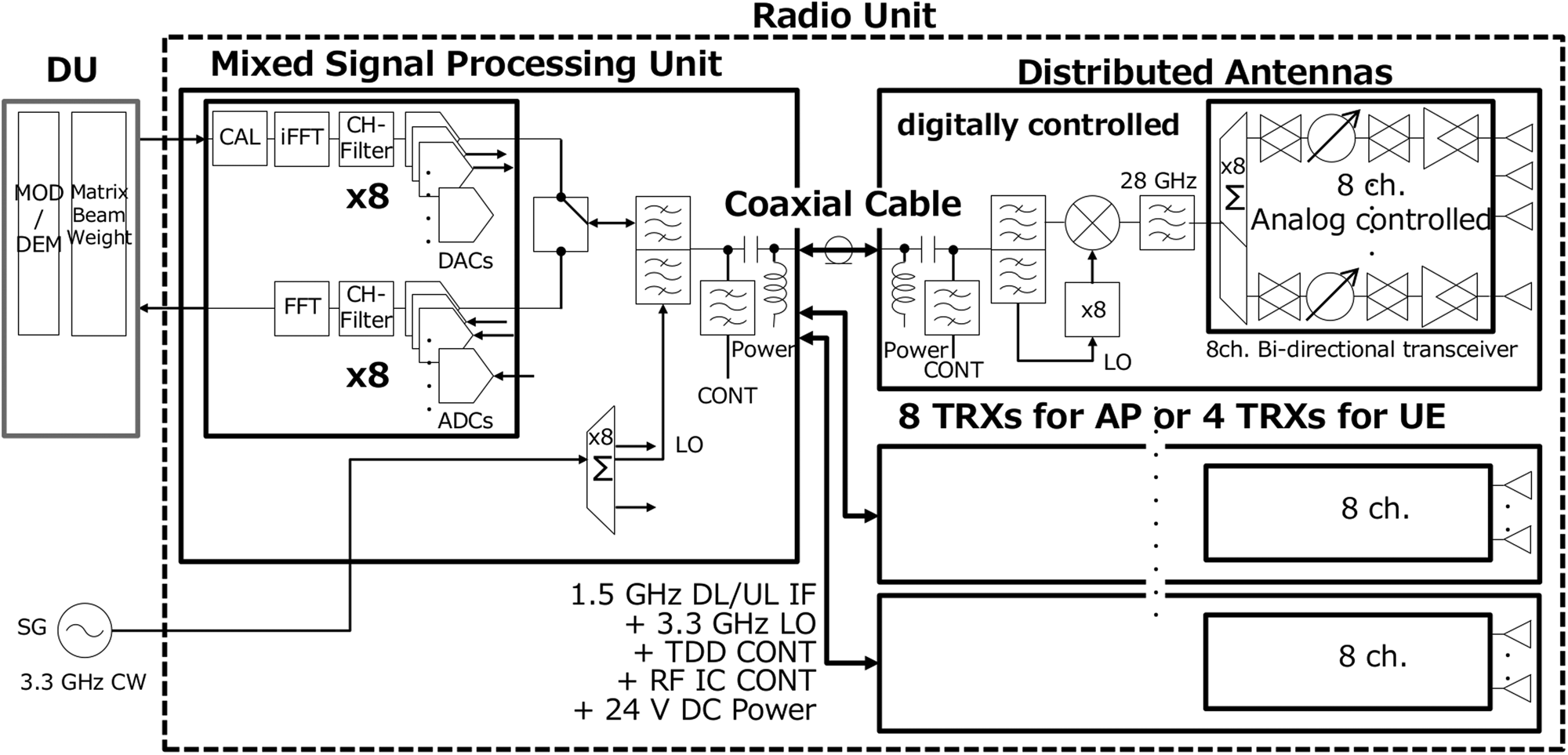
DA converts between the IF signals and 28.25 GHz RF signals by mixing with an LO signal produced by eight times of an original 3.3 GHz signal. Each DA has eight element waveguide array antenna having vertical polarization and vertically aligning with element intervals of half wave length at 28 GHz. The eight antenna elements connect to the eight channel bi-directional transceiver IC based on 65 nm CMOS integrating gain and phase shifters [Reference Pang, Li, Kubozoe, Luo, Wu, Wang, You, Fadila, Saengchan, Nakamura, Alvin, Matsumoto, Liu, Narayanan, Qiu, Liu, Sun, Huang, Tokgoz, Motoi, Oshima, Hori, Kunihiro, Kaneko, Shirane and Okada8]. The measured effective isotropic radiated power of DA is 22 dBm.
Measurement setup
Figure 5 shows the experimental layout of eight DAs, DA0–DA7, and four UEs, UE0–UE3, on an office floor. The heights of DAs and UEs are about 1.7 m from the floor. The UE systems have the same architecture as the AP D-MIMO system except for the number of antenna units, and thus UEs can be located at arbitrary places on the floor. UEs are located in the line of sight of any of DAs. Thus, the direct waves from UEs to DAs are dominant, and the effects of multipath and varying polarization are relatively low. UE0 is used for single-user measurements, and UE0 and UE1 are used for two-user multiplexing. Our measurements have three parts as follows. In part-0, UE0 is fixed at the initial locations, and its carrier frequency is shifted by 4 kHz, which corresponds to the Doppler effect of a 42 m/s moving UE, by changing LO frequency to confirm Doppler effect of a high speed UE. In part-1, UE0 moves to left direction as shown in Fig. 5 at walking speed, whereas the other UEs are fixed at the initial locations. Because CIR is spread in the Doppler domain for mobility environments, the CIR-RS analysis range of the Doppler domain for UE0, k r,u=0, is three as shown in Table 1. The CIR-RS analysis ranges k r,u for the other UEs are zero to decrease AWGN contaminated to the channel estimation. In part-2, all UEs are fixed at the initial locations, and their CIR-RS analysis ranges k r,u are zero.
Experimental layout on the office floor. The Antenna directions of DAs and UEs correspond to the directions of antenna symbols.

Measurement results and discussion
Figure 6(a) shows phase of the EQ2 correction parameter, $c_{i( {l\in l_p, k} ) }$ , in the part-0 measurement, which has the gradient of −0.020° per delay index as shown by the solid line. The gradient corresponds to exp( − j2πf ot sM Fl/M) in (17), where f o = 4 kHz in this measurement. In a high-mobility environment, the UE moving speed in the direction of arrival (DOA) can be estimated using the phase gradient of the correction parameter. Figure 6(b) shows the UE0 OTFS constellations in a symbol in the part-0 measurement. Although the constellation before EQ2 rotates by the frequency offset as shown in (16), the constellation after EQ2 concentrates at the original QPSK position.
(a) Phase of the EQ2 correction parameter in the part-0 measurement. The solid line shows the best fit linear function obtained from the measured correction parameter. (b) OTFS constellations before and after EQ2 in the part-0 measurement.
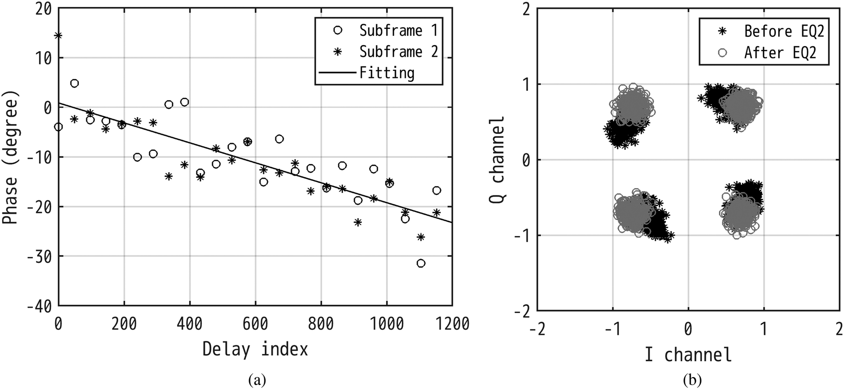
Figure 7 shows the UE0 OTFS constellations in the part-1 measurements. The constellation before EQ2 shown in Fig. 7(a) is rotated at $\omega = 14^\circ$ per subframe by the Doppler effect, which is expressed as exp(j2πf ot sM FNi) in (16). Thus, the frequency shift is estimated as ω/(2πt sM FN) = 150 Hz, where M FN is 30 720 by considering cyclic prefix, which indicates the UE0 moving speed of 5.8 km/h in the DOA. In a low-mobility environment, the UE moving speed in the DOA can be estimated using the phase variation of the EQ2 correction parameter per subframe. EQ2 corrects the Doppler effect by using PCRS and (4), and obtains the RX DD-domain signal as shown in Fig. 7(b).
Measured UE0 OTFS QPSK constellations (a) without using EQ2 and (b) using EQ2.
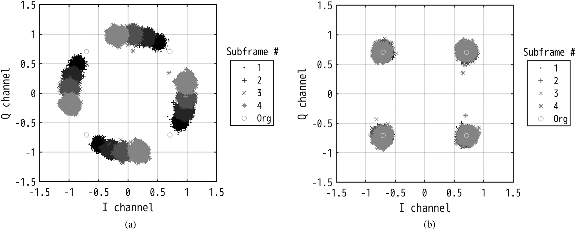
Figure 8 shows the measured error vector magnitudes (EVMs), which are calculated from the demodulated signal ${\bf z}_{i( {l, k} ) }^{{\rm EQ2}}$ on the PC based on 3GPP TS 38.141 [9], as a function of the number of simultaneously connected UEs. AP D-MIMO can demodulate the multi-user OTFS signals, which are emitted in the same frequency band and the same time, with ZF in the actual OTA and Doppler environments. In the part-2 measurements, with all UEs are fixed, the OTFS EVMs are about the same as the OFDM EVMs regardless of the number of connected UEs. In contrast, the EVMs of the moving OTFS UE0 in the part-1 measurements are several dB less than those of the moving OFDM UE0, which is shown by the solid black circles in Fig. 8. The solid gray circle in Fig. 8(b) shows the EVMs of the moving OFDM UE0 using phase tracking reference signals (PTRSs). PTRS is based on the specifications in 3GPP TS 38.211 [10], which is allocated for each 48 subcarrier intervals in 4th–14th OFDM symbols for each subframe. The OFDM EVMs of UE1–UE3 with PTRS are about the same as those without PTRS because these UEs are fixed. Although the moving OFDM UE0 with PTRS has less EVM than the moving OTFS UE0, computational complexity for equalizations increases to use PTRS. The computational complexity to obtain the equalization weight W(m,n) of each element is ${\cal O}( {U^3 + DU^2} )$
 , and thus the computational complexity of all elements in a subframe is ${\cal O}( {MN( {U^3 + DU^2} ) } )$
 . The OTFS demodulator calculates the equalization weights of all elements in a subframe for each 10 subframes, whereas the OFDM demodulator using PTRS calculates the weights for each subframe. Thus, the computational complexity to obtain the equalization weights of OFDM using PTRS is 10 times greater than that of OTFS.
Measured EVMs as a function of the number of UEs with (a) OTFS and (b) OFDM.
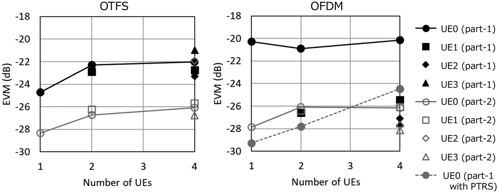
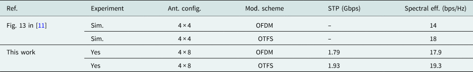
Table 2 shows comparison with the previously reported OTFS and OFDM systems without using PTRS. The system throughput (STP) and spectral efficiency of this work are estimated from the UE0 EVMs in the part-1 measurements by using the MATLAB 5G toolbox. The STP is sum of four-user throughputs with 100 MHz bandwidth signals. Although the improvement in spectral efficiencies from OFDM to OTFS is not large because of the low UE moving speed such as walking, the experimentally estimated spectral efficiencies of this work are compatible with those of the previous work [11] calculated by simulation.
Comparison with the previously reported OTFS systems
Conclusion
This paper presented experimental investigation of OTFS performances using the 28 GHz D-MIMO testbed in OTA and mobility environments. We built the D-MIMO testbed including the OTFS modulator and demodulator, and measured EVM with up to four user simultaneous connections on the actual office floor. To our knowledge, this is a first experimental verification of EVM, throughput, and spectral efficiency using OTFS modulation in 28 GHz OTA environments.
The newly developed OTFS demodulator corrected the large- and small-frequency offset and indicated that the Doppler effect on OTFS signals corresponds to the mathematical analysis. OTFS has less EVM and higher spectral efficiency than OFDM without PTRS for moving UE and has higher robustness in time-variant channels. Additionally, the OTFS demodulator estimated the frequency offset, which has the possibility to estimate the moving velocity of UE. These findings suggest that OTFS is one of the key technologies to realize 5G or later mobile communication systems used for high-mobility environments and in high-frequency range such as mmWave and sub-THz.
Supplementary material
The supplementary material for this article can be found at https://doi.org/10.1017/S1759078722001209.
Acknowledgement
This research is partially supported by the Ministry of Internal Affairs and Communications in Japan (JPJ000254).
Conflict of interest
The authors report no conflict of interest.
 Noriaki Tawa received his B.Sc. degree from Hiroshima University, Japan, in 2003, and his M.Sc. and Ph.D. degrees from Osaka University, Japan, in 2005 and 2008, respectively. He had received research fellowships from Japan Society for the Promotion of Science from 2007 to 2008. In 2008 he joined NEC Corporation where he has been engaged in high-efficiency PAs and bit-streamer technologies development for base-stations. He is currently focusing on the digital beam-forming massive MIMO technology in the quasi-/millimeter-wave frequency range and high-efficiency PAs in sub-6 GHz range.
 Toshihide Kuwabara received his B.E. and M.E. degrees in electrical engineering from Waseda University, Japan, in 1991 and 1993, respectively. Currently, he is a senior engineer at NEC Corporation. His main development work is the design and optimization of millimeter-wave and sub-terahertz radios. He is serving as a TPC member of the IEEE BiCMOS and Compound Semiconductor Integrated Circuits and Technology Symposium (BCICTS).
 Yasushi Maruta received his B.E. degree in electrical engineering and his M.E. degree in electronics from Tohoku University in 1994 and 1996, respectively. He joined NEC Corporation in 1996, where he has been engaged in the development of baseband signal processing parts in base-stations for mobile wireless communication. He is currently focusing on massive-MIMO technology enhancement in millimeter-wave and sub-terahertz frequency range.
 Tomoya Kaneko received his B.S. degree in physics from the Tokyo University of Science, Japan and his M.S. degree in science from the University of Tsukuba, Japan, in 1984 and 1986, respectively. He joined NEC Corporation, Japan in 1986, where he has been engaged in design and development of microwave and millimeter-wave circuits, their MCMs and sub-systems for radio communication systems. From 1999 to 2002, he was an engineer at NEC America Inc., USA, where he developed GaAs MMICs for millimeter-wave P-P radios. He is currently a senior professional in Wireless Access Development Department of NEC Corporation. His current interests are millimeter-wave technologies and massive-MIMO considering their application to the mobile access networks. He had been serving as a TPC member and an overseas advisor for the IEEE BiCMOS and Compound Semiconductor Integrated Circuits and Technology Symposium (BCICTS) for 12 years.


 Open access