


Impact Statement
Adding new energy sources, such as wind and solar, to the energy grid causes different loadings on hydroelectric turbines, which can cause fatigue and reduce turbine longevity. Turbines’ fatigue life and longevity are defined by their dynamical properties, which are heavily affected under fluid loads, as flow-added quantities become important. Evaluating flow-added damping is computationally difficult and rarely done during turbine design due to heavy numerical costs. Current studies include developing new methods to evaluate these flow-added effects and focus on obtaining experimental data to validate these new methods. Common test cases are hydrofoils, with similar geometries to turbine blades but a simpler dynamics. We develop a new simple, fast and reliable method to evaluate flow-added damping on hydrofoils. A good agreement between this method and existing experimental and numerical results is observed. Developing this method for more complex structures, such as cascades and turbine runners, could help design turbines for flow-added damping.
1. Introduction
Every hydraulic turbine is tailor made for the hydroelectric power station where it is installed to maximize its efficiency (Reference Coutu, Seeley, Monette, Nennemann and MarmontCoutu et al. 2012; Reference Monette, Nennemann, Seeley, Coutu and MarmontMonette et al. 2014; Reference Gauthier, Giroux, Etienne and GosselinGauthier et al. 2017) and support the load cases it will endure during its lifetime. Turbines are majorly impacted by fluid–structure interactions (FSI), which can lead to complex dynamic behaviours (Reference Coutu, Seeley, Monette, Nennemann and MarmontCoutu et al. 2012; Reference Monette, Nennemann, Seeley, Coutu and MarmontMonette et al. 2014; Reference Nennemann, Monette and Chamberland-LauzonNennemann, Monette & Chamberland-Lauzon 2016), especially during off-design operations (Reference Dehkharqani, Aidanpää, Engström and CervantesDehkharqani et al. 2019) such as the start up, spin no load and load rejection.
Turbine designers must know what will be the magnitude of a turbine blade's vibrations under different excitations (Reference Bergan, Tengs, Solemslie, Østby and DahlhaugBergan et al. 2019b), as it will determine its fatigue life. Vibration amplitude is heavily dependent on its damping coefficient (Reference Coutu, Seeley, Monette, Nennemann and MarmontCoutu et al. 2012; Reference Gauthier, Giroux, Etienne and GosselinGauthier et al. 2017; Reference Zeng, Wang, Huang, Wang, Xiao and YaoZeng et al. 2023) and turbine designers typically accept a large safety factor on the damping coefficient to determine whether the turbine will be unstable or experience sufficiently large cyclic deformations to damage the turbine under flow. Indeed, rotor–stator interaction is an unavoidable source of excitation for hydroelectric turbines, which causes a forced response dependent on the excitation frequency and the system damping (Reference Seeley, Patil, Madden, Connell, Hauet and ZoriSeeley et al. 2019) that can lead to early cracks and fatigue failure (Reference Coutu, Seeley, Monette, Nennemann and MarmontCoutu et al. 2012; Reference Monette, Nennemann, Seeley, Coutu and MarmontMonette et al. 2014; Reference Nennemann, Monette and Chamberland-LauzonNennemann et al. 2016; Reference Gauthier, Giroux, Etienne and GosselinGauthier et al. 2017) if the turbine suffers large amplitude cyclic load due to an insufficiently large damping.
The system damping is dominated by flow-added damping and structural damping is expected to be insignificant (Reference Seeley, Coutu, Monette, Nennemann and MarmontSeeley et al. 2012; Reference Dehkharqani, Aidanpää, Engström and CervantesDehkharqani et al. 2019; Reference Zeng, Wang, Huang, Wang, Xiao and YaoZeng et al. 2023). Currently, hydroelectric turbine designers rely on empirical methods to estimate flow-added damping, which is adequate as long as the turbine design remains conventional and an important safety factor is considered. Reference Dehkharqani, Aidanpää, Engström and CervantesDehkharqani et al. (2019) reviews different analytical, experimental and numerical methods to evaluate fluid-added quantities for hydraulic turbines. These methods include computational fluid dynamics (CFD) using deforming meshes (Reference Monette, Nennemann, Seeley, Coutu and MarmontMonette et al. 2014; Reference Gauthier, Giroux, Etienne and GosselinGauthier et al. 2017; Reference Seeley, Patil, Madden, Connell, Hauet and ZoriSeeley et al. 2019) and coupling the fluid dynamics with a structural dynamics analysis (Reference Falcucci, Aureli, Ubertini and PorfiriFalcucci et al. 2011; Reference Liaghat, Guibault, Allenbach and NennemannLiaghat et al. 2014; Reference Cupr, Rudolf and HabánCupr, Rudolf & Habán 2018; Reference Tengs, Bergan, Jakobsen and StorliTengs et al. 2019), but these have been proven to be numerically expensive and complex to set up for analysis (Reference Nennemann, Monette and Chamberland-LauzonNennemann et al. 2016; Reference Gauthier, Giroux, Etienne and GosselinGauthier et al. 2017). There has therefore been an increasing interest in developing time-efficient procedures for evaluating flow-added damping (Reference Seeley, Patil, Madden, Connell, Hauet and ZoriSeeley et al. 2019). Several studies have also been focused on obtaining experimental data regarding the damping of simplified hydrofoil geometries (Reference Blake and MagaBlake & Maga 1975; Reference Coutu, Seeley, Monette, Nennemann and MarmontCoutu et al. 2012; Reference Bergan, Tengs, Solemslie and DahlhaugBergan et al. 2019a, Reference Bergan, Tengs, Solemslie, Østby and Dahlhaugb), which can be used to validate novel flow-added damping evaluation methods. The effect of other parameters like the angle of attack was also studied experimentally (Reference ReeseReese 2010).
A common point to the previously mentioned methods is that they are CFD-based approaches. Using alternative solutions that do not rely on unsteady Reynolds-averaged Navier–Stokes (URANS) simulations with deforming meshes to evaluate flow-added damping can decrease the solution time in an important manner. Flow-added damping arises from the same mechanism that gives rise to the aeroelastic instability phenomenon of flutter (Reference FungFung 2008; Reference DowellDowell 2015). At small and moderate reduced velocities, flutter models predict an increase in damping with the passage of flow on an airfoil. It therefore seems reasonable to think that we can represent flow-added damping effects using previously defined flutter analysis methods.
The British method (Reference Frazer and DuncanFrazer & Duncan 1928; Reference Lawrence and JacksonLawrence & Jackson 1970), which follows Hassig's terminology as the PK method (Reference HassigHassig 1971) implemented in NASTRAN's SOL 145 (Siemens 2014a), is a method to solve the aeroelastic stability problem by adding stiffness and damping terms, which are functions of the structure's frequency and the flow velocity, to the eigenvalue problem. This method is applied in the modal basis, which therefore takes computational advantage of the reduced-order model nature of this basis. NASTRAN's SOL 145 is ideal for extracting the flow-added damping coefficient of lighter fluids such as air, as it is possible to obtain the damping coefficient and natural frequency according to the flow velocity.
To compute the added stiffness and damping terms in the PK method, the doublet-lattice method is used to reproduce a uniform and inviscid flow around the hydrofoil, with the perturbations caused by the hydrofoil's motion, and non-penetration conditions are imposed on the aerodynamic panels as well as instantaneous respect for the Kutta condition. It is important to note that the ideal fluid assumption is used within the aerodynamic load matrices in the PK method, which removes any vortex-induced vibrations from these analyses.
However, simply modifying the flow density in NASTRAN's SOL 145 will not produce interesting results, as NASTRAN does not reproduce the added mass effect within the aeroelasticity module. It is possible to reproduce this added mass effect using the added virtual mass incremental (AVMI) factor  $\beta$ (Reference Kwak and KimKwak & Kim 1991; Reference Amabili and KwakAmabili & Kwak 1996; Reference Louyot, Nennemann, Monette and GosselinLouyot et al. 2020). This is possible due to the common assumption in hydrodynamics that the vacuum mode shapes are the same as the resting fluid mode shapes (Reference Liang, Rodríguez, Egusquiza, Escaler, Farhat and AvellanLiang et al. 2007; Reference Monette, Nennemann, Seeley, Coutu and MarmontMonette et al. 2014; Reference Gauthier, Giroux, Etienne and GosselinGauthier et al. 2017) with varying natural frequencies. This assumption can be verified using the modal assurance criterion (Reference Pastor, Binda and HarčarikPastor, Binda & Harčarik 2012).
Reference Zeng, Wang, Huang, Wang, Xiao and YaoZeng et al. (2023) developed a comprehensive empirical equation (CEE) for the flow-added damping of hydrofoils. They take into account several geometry parameters in their model such as tip clearance, angle of attack and flow velocity, with the objective of providing a general estimation for all types of hydrofoils.
Here, we present a methodology based on reduced-order models, modal, vibro-acoustic and aeroelastic analysis methods to study flow-added damping on hydrofoils. The objective is to develop a method that both does not rely on interpolation techniques like empirical equation methods, which are by definition limited in the range of the available data, and is not computationally expensive like CFD, one-way and two-way coupled methods. The method presented here is based on a physical model, with some assumptions, but remains simple and fast to compute. This paper first presents the physical model to be evaluated and then proceeds to describe the different applied analyses using NASTRAN's multiple modules for evaluating the damping coefficient of a hydrofoil. Finally, simple hydrofoils are tested and compared with experimental and numerical data obtained from existing literature. A conclusion regarding the solution's time and accuracy is presented.
2. Methodology
2.1 Physical model
The equation of motion governing the discretized displacement  $\{\boldsymbol{u}_s\}$ of a structure, such as a hydrofoil or a turbine, can be written as
 \begin{equation}
[\boldsymbol{\mathsf{M}}_s]\{\ddot{\boldsymbol{u}}_s\} + [\boldsymbol{\mathsf{C}}_s]\{\dot{\boldsymbol{u}}_s\} + [\boldsymbol{\mathsf{K}}_s]\{\boldsymbol{u}_s\} = \{\boldsymbol{F}(t)\},
\end{equation}
\begin{equation}
[\boldsymbol{\mathsf{M}}_s]\{\ddot{\boldsymbol{u}}_s\} + [\boldsymbol{\mathsf{C}}_s]\{\dot{\boldsymbol{u}}_s\} + [\boldsymbol{\mathsf{K}}_s]\{\boldsymbol{u}_s\} = \{\boldsymbol{F}(t)\},
\end{equation}
where  $\boldsymbol{\mathsf{M}}_s$ is the structural mass matrix, $\boldsymbol{\mathsf{C}}_s$ is the structural damping matrix, $\boldsymbol{\mathsf{K}}_s$ is the structural stiffness matrix and $\boldsymbol{F}(t)$ is the load vector, with the $\dot {(\,)}$ notation used to represent time differentiation. However, considering a heavy fluid such as water induces added effects on the hydrofoil (Reference Gauthier, Giroux, Etienne and GosselinGauthier et al. 2017), which requires that we rewrite the equation of motion as
 \begin{equation}
([\boldsymbol{\mathsf{M}}_s] + [\boldsymbol{\mathsf{M}}_F])\{\ddot{\boldsymbol{u}}_s\} + ([\boldsymbol{\mathsf{C}}_s] + [\boldsymbol{\mathsf{C}}_F])\{\dot{\boldsymbol{u}}_s\} +
([\boldsymbol{\mathsf{K}}_s] + [\boldsymbol{\mathsf{K}}_F])\{\boldsymbol{u}_s\} = \{\boldsymbol{F}_s(t)\},
\end{equation}
\begin{equation}
([\boldsymbol{\mathsf{M}}_s] + [\boldsymbol{\mathsf{M}}_F])\{\ddot{\boldsymbol{u}}_s\} + ([\boldsymbol{\mathsf{C}}_s] + [\boldsymbol{\mathsf{C}}_F])\{\dot{\boldsymbol{u}}_s\} +
([\boldsymbol{\mathsf{K}}_s] + [\boldsymbol{\mathsf{K}}_F])\{\boldsymbol{u}_s\} = \{\boldsymbol{F}_s(t)\},
\end{equation}
with  $\boldsymbol{\mathsf{M}}_F$ the added mass matrix, $\boldsymbol{\mathsf{C}}_F$ the added damping matrix, $\boldsymbol{\mathsf{K}}_F$ the added stiffness matrix and $\boldsymbol{F}_s(t)$ the residual load vector applied to the structure. By assuming a solution of the form $\{\boldsymbol{u}_s(t)\} = Re(\{\boldsymbol{\phi}_i\}\,\textrm {e}^{p_i t})$, with $\boldsymbol{\phi}_i$ an eigenmode, $p_i$ the corresponding eigenvalue and $t$ the time, for the free vibration problem such that $\boldsymbol{F}_s(t) = 0$, the following eigenvalue problem is obtained:
 \begin{equation} Re((p_i^2 ([\boldsymbol{\mathsf{M}}_s] + [\boldsymbol{\mathsf{M}}_F]) + p_i ([\boldsymbol{\mathsf{C}}_s] + [\boldsymbol{\mathsf{C}}_F]) + ([\boldsymbol{\mathsf{K}}_s] + [\boldsymbol{\mathsf{K}}_F]))\{\boldsymbol{\phi}_i\}\,\textrm{e}^{p_i t}) = \{0\}. \end{equation}
Assuming that the system possesses orthogonal modes, the equation of motion in the modal basis is
 \begin{align} & ([\boldsymbol{\mathsf{M}}_{hh,s}] + [\boldsymbol{\mathsf{M}}_{hh,F}])\{\ddot{\boldsymbol{u}}_h\} + ([\boldsymbol{\mathsf{C}}_{hh,s}] + [\boldsymbol{\mathsf{C}}_{hh,F}]) \{\dot{\boldsymbol{u}}_h\} + ([\boldsymbol{\mathsf{K}}_{hh,s}] + [\boldsymbol{\mathsf{K}}_{hh,F}])\{\boldsymbol{u}_h\} \nonumber\\ &\quad = [\varPhi]^{\rm T} \{\boldsymbol{F}_s(t)\}, \end{align}
where  $\boldsymbol{u}_h$ are the modal coordinates such that $\{\boldsymbol{u}_s\}=[\boldsymbol{\varPhi}]\{\boldsymbol{u}_h\}$, $\boldsymbol{\varPhi} = [\boldsymbol{\phi} _1 \boldsymbol{\phi} _2 \cdots ]$ is the eigenvector matrix, $\boldsymbol{\mathsf{M}}_{hh, s}$ is the structural modal mass matrix, $\boldsymbol{\mathsf{C}}_{hh,s}$ is the structural modal damping matrix, $\boldsymbol{\mathsf{K}}_{hh,s}$ is the structural modal stiffness matrix, $\boldsymbol{\mathsf{M}}_{hh, F}$ is the fluid modal mass matrix, $\boldsymbol{\mathsf{C}}_{hh, F}$ is the fluid modal damping matrix and $\boldsymbol{\mathsf{K}}_{hh,F}$ is the fluid modal stiffness matrix. For very small damping, the previously obtained eigenvalue can also be rewritten as (Reference HassigHassig 1971; Siemens 2014a)
 \begin{equation} p_i = \omega_{i}(-\zeta_i \pm j), \end{equation}
with  $\zeta _i$ the dimensionless modal damping coefficient, $\omega _{i}$ the modal angular frequency such that $\omega _{i} = 2{\rm \pi} f_{i}$, where $f_{i}$ is the natural frequency, since the damped modal angular frequency is approximately equal to the undamped modal angular frequency with small damping. Therefore, the free vibration modes become (Siemens 2019)
 \begin{equation} \{\boldsymbol{u}_s(t)\} =
Re(\{\boldsymbol{\phi}_i\} \exp({-\zeta_i\omega_i t}) (\cos(\omega_{i}
t) \pm j\sin(\omega_{i} t))) = \{\boldsymbol{\phi}_i\}
\exp({-\zeta_i\omega_i t})\cos(\omega_{i} t).
\end{equation}
\begin{equation} \{\boldsymbol{u}_s(t)\} =
Re(\{\boldsymbol{\phi}_i\} \exp({-\zeta_i\omega_i t}) (\cos(\omega_{i}
t) \pm j\sin(\omega_{i} t))) = \{\boldsymbol{\phi}_i\}
\exp({-\zeta_i\omega_i t})\cos(\omega_{i} t).
\end{equation}
The dimensionless damping coefficient  $\zeta _i$, the natural frequency $f_{i}$ and the mode shapes $\phi _i$ therefore encapsulate the dynamics of a mechanical system and allow the evaluation of the vibration amplitude for a given forcing. The mode shapes, being similar both in vacuum and in a fluid at rest, can be obtained from modal analysis. The natural frequencies being influenced mostly by the added mass can be evaluated using vibro-acoustic modal analysis. However, the flow-added damping coefficient is caused by the $\boldsymbol{\mathsf{C}}_F$ matrix, which requires a fluid dynamics analysis. Therefore, we propose the following method to evaluate the damping coefficient $\zeta _i$ more efficiently.
2.2 Aeroelastic analysis
The flow-added damping originates from the same mechanism responsible for the aeroelastic instability phenomenon known as flutter. The flow-added damping is essentially the exchange of energy between the fluid and a vibrating structure. It can be interpreted as the work between the structure and the fluid over a vibration cycle (Reference Monette, Nennemann, Seeley, Coutu and MarmontMonette et al. 2014). If the overall energy increases, the damping is negative, leading to flutter, whereas if it decreases, the amplitude of the vibrations will reduce and the structure is damped by the presence of the fluid. We can therefore represent flow-added damping effects using previously defined flutter analysis methods. In order to evaluate the dimensionless damping coefficient, the PK method from NX NASTRAN's aerodynamic flutter analysis (SOL 145) (Siemens 2014a) can be used for lighter fluids. As mentioned, the PK method solves the aerodynamic stability problem by adding velocity-dependent stiffness and damping terms to the eigenvalue problem. The eigenvalue problem studied with the PK method is
 \begin{equation}
\left([\boldsymbol{\mathsf{M}}_{hh,s}]p_{i}^2 +
\left([\boldsymbol{\mathsf{C}}_{hh,s}] - \frac{1}{2f_{i}}\rho
U^2[\boldsymbol{\mathsf{Q}}_{hh}^I]\right)p_{i} +
\left([\boldsymbol{\mathsf{K}}_{hh,s}]-\frac{1}{2}\rho U^2 [\boldsymbol{\mathsf{Q}}_{hh}^R]
\right) \right)\{\boldsymbol{u}_h\} = \{0\},
\end{equation}
\begin{equation}
\left([\boldsymbol{\mathsf{M}}_{hh,s}]p_{i}^2 +
\left([\boldsymbol{\mathsf{C}}_{hh,s}] - \frac{1}{2f_{i}}\rho
U^2[\boldsymbol{\mathsf{Q}}_{hh}^I]\right)p_{i} +
\left([\boldsymbol{\mathsf{K}}_{hh,s}]-\frac{1}{2}\rho U^2 [\boldsymbol{\mathsf{Q}}_{hh}^R]
\right) \right)\{\boldsymbol{u}_h\} = \{0\},
\end{equation}
with  $\boldsymbol{\mathsf{Q}}_{hh}$ the modal aerodynamic influence matrix, where its imaginary part $\boldsymbol{\mathsf{Q}}_{hh}^I$ is used as a damping term and its real part $\boldsymbol{\mathsf{Q}}_{hh}^R$ is used as a stiffness term. Moreover, $\rho$ is the fluid density and $U$ is the flow velocity. As stated, the modal aerodynamic influence matrices are computed using doublet-lattice panels, which imposes a non-penetration boundary condition on the surface of vibrating airfoils as well as forcing the Kutta condition at the trailing edge. For future comparisons, the reduced velocity, $U_{R} = {U}/{f_{1,fr}h}$, with $f_{1,fr}$ the fundamental natural frequency in resting water and $h$ the hydrofoil's maximum thickness, will be used to allow for comparison between different structures. It is to be noted that (2.7) is written differently in NASTRAN's documentation (Siemens 2014a), using the reduced frequency $k$ notation such that $k = {f_{i,vac} c}/{2U}$, with $c$ the aerodynamic chord and $f_{i,vac}$ the modal frequencies in vacuum so that the emphasis is placed on the fluid rather than the structure's vibrational characteristics. Moreover, we change the scaling from using the aerodynamic chord to the thickness so that the reduced velocity has a direct link to the vortex shedding frequency. Indeed, when considering vortex shedding, it is common for the Strouhal number to be defined using the thickness of the structure rather than its characteristic length, whereas aeroelastic analyses might use different conventions. This change of scaling is therefore used to ease the understanding of what the reduced velocity represents.
Equation (2.7) is similar to (2.4), except the added mass matrix is absent. Therefore, it is required to reproduce the added mass effect artificially for the aeroelastic analysis to be applicable, since this module will allow us to extract the damping coefficient  $\zeta _i$. This added mass effect is typically calculated using a finite element analysis (FEA) integrating acoustic fluid, which is also the chosen method to evaluate this added effect here.
2.3 Recreation of the added mass effect
Due to the assumption of similar mode shapes in vacuum and in resting fluid, the vacuum natural frequencies can be linked to the resting fluid natural frequencies using the AVMI factor  $\beta$ (Reference Kwak and KimKwak & Kim 1991; Reference Amabili and KwakAmabili & Kwak 1996; Reference Louyot, Nennemann, Monette and GosselinLouyot et al. 2020). This factor is defined by the ratio of the natural frequencies such that
 \begin{equation} \frac{\omega_{i,fr}}{\omega_{i,vac}} = \frac{1}{\sqrt{1 + \beta_i}}, \end{equation}
where  $\omega _{i,fr}$ is the $i$th angular natural frequency in resting fluid, $\omega _{i,vac}$ is the $i$th angular natural frequency in vacuum and $\beta _i$ is the AVMI factor for the $i$th mode. Considering that (2.5) still holds and since there is no added damping between the hydrofoil in vacuum and the hydrofoil in resting fluid, this leads to
 \begin{equation} \frac{\omega_{i,fr}}{\omega_{i,vac}} = \frac{p_{i,fr}}{p_{i,vac}} = \frac{1}{\sqrt{1 + \beta_i}}, \end{equation}
where  $p_{i,fr}$ is the eigenvalue for the problem in resting fluid and $p_{i,vac}$ is the eigenvalue for the problem in vacuum. However, in the modal basis, where each mode has a corresponding modal mass $m_i$ and modal stiffness $k_i$ lying on the diagonal of the mass matrix $\boldsymbol{\mathsf{M}}_{hh,s}$ and stiffness matrix $\boldsymbol{\mathsf{K}}_{hh,s}$, respectively, we can also define the natural frequencies $\omega _{i,vac} = \sqrt {{k_i}/{m_{s,i}}}$, with $m_{s,i}$ the structural modal mass, and $\omega _{i,fr}=\sqrt {{k_i}/{(m_{s,i}+m_{f,i})}}$, with $m_{f,i}$ the flow-added modal mass (Reference Gauthier, Giroux, Etienne and GosselinGauthier et al. 2017). This leads to
 \begin{equation} \frac{\omega_{i,fr}}{\omega_{i,vac}} = \frac{\sqrt{\dfrac{k_i}{m_{s,i} + m_{f,i}}}}{\sqrt{\dfrac{k_i}{m_{s,i}}}} = \sqrt{\frac{m_{s,i}}{m_{s,i} + m_{f,i}}} = \frac{1}{\sqrt{1 + \beta_i}}. \end{equation}
By posing  $P_i = \sqrt {1+\beta _i} = {\omega _{i,vac}}/{\omega _{i,fr}}$, we can rewrite (2.10) as
 \begin{equation} m_{s,i} + m_{f,i} = m_{s,i}P_i^2. \end{equation}
Generalizing (2.11) to its matrix equivalent, we find
 \begin{equation} [\boldsymbol{\mathsf{M}}_{hh,s}] + [\boldsymbol{\mathsf{M}}_{hh,f}]
= [\boldsymbol{\mathsf{M}}_{hh,s}][P^2],
\end{equation}
\begin{equation} [\boldsymbol{\mathsf{M}}_{hh,s}] + [\boldsymbol{\mathsf{M}}_{hh,f}]
= [\boldsymbol{\mathsf{M}}_{hh,s}][P^2],
\end{equation}
since all modal matrices are diagonal due to the orthogonal modes hypothesis. Therefore, to add the flow-added mass effect, we rewrite (2.7) as
 \begin{equation} \left([\boldsymbol{\mathsf{M}}_{hh,s}][P^2]p_{i}^2 + \left([\boldsymbol{\mathsf{C}}_{hh,s}] - \frac{1}{2f_{i}}\rho U^2[\boldsymbol{\mathsf{Q}}_{hh}^I]\right)p_{i} + \left([\boldsymbol{\mathsf{K}}_{hh,s}]-\frac{1}{2}\rho U^2 [\boldsymbol{\mathsf{Q}}_{hh}^R] \right) \right)\{\boldsymbol{u}_h\} = \{\boldsymbol{0}\}. \end{equation}
 By extracting the vacuum modal frequencies and resting fluid modal frequencies using NASTRAN's real eigenvalue analysis (SOL 103) and direct complex eigenvalue analysis (SOL 107), a modal AVMI matrix  $[P]$ can be constructed to recreate the adequate natural frequencies while maintaining appropriate mode shapes. Thus, (2.13) allows us to calculate the flow-added damping coefficient $\zeta _i$ and use the flutter solution for hydroelastic purposes. These multiplications can be done in the DMAP commands (Siemens 2014b) used in NASTRAN.
3. Results
3.1 Hydrofoils and materials
To validate the method described in § 2, structural response data from five different test cases based on hydrofoils were used. Reference Roth, Calmon, Farhat, Münch, Bjoern and AvellanRoth et al. (2009), Reference Cupr, Rudolf and HabánCupr et al. (2018), Reference Bergan, Tengs, Solemslie and DahlhaugBergan et al. (2019a), Reference Bergan, Tengs, Solemslie, Østby and DahlhaugBergan et al. (2019b), Reference Tengs, Bergan, Jakobsen and StorliTengs et al. (2019) and Reference Zeng, Yao, Zhou, Wang and HongZeng et al. (2019) all present results for several different hydrofoils, materials and conditions. The first hydrofoil is a modified NACA0003, such that its trailing edge has a 1 mm thickness, studied on ANSYS CFX using two-way coupling (Reference Cupr, Rudolf and HabánCupr et al. 2018). The second hydrofoil, named F0, is the third Francis99 workshop hydrofoil made of aluminium (Reference Bergan, Tengs, Solemslie and DahlhaugBergan et al. 2019a, Reference Bergan, Tengs, Solemslie, Østby and Dahlhaugb; Reference Tengs, Bergan, Jakobsen and StorliTengs et al. 2019) and studied experimentally. The third hydrofoil, named F1, is also made of aluminium and is studied both experimentally and numerically using one-way coupling (Reference Bergan, Tengs, Solemslie and DahlhaugBergan et al. 2019a, Reference Bergan, Tengs, Solemslie, Østby and Dahlhaugb; Reference Tengs, Bergan, Jakobsen and StorliTengs et al. 2019). Finally, the last two hydrofoils are both NACA0009 but with different trailing edges, ‘Donaldson trailing edge’ and ‘blunt trailing edge’, as described in Reference Zeng, Yao, Zhou, Wang and HongZeng et al. (2019). Reference Zeng, Yao, Zhou, Wang and HongZeng et al. (2019) studied both hydrofoils numerically using two-way coupling, while Reference Roth, Calmon, Farhat, Münch, Bjoern and AvellanRoth et al. (2009) studied the blunt trailing edge hydrofoil experimentally. In the first three mentioned cases, the hydrofoils are clamped at both ends whereas in the last two cases, they are only clamped at one end and free at the other. The five hydrofoils are presented in figure 1(a) and their specifications are presented in table 1. For the five hydrofoils, the velocity range that was tested was between 0 and 28 m s $^{-1}$, which, for the F0 and F1 hydrofoils, crosses the vortex-induced vibration lock-in region (Reference Bergan, Tengs, Solemslie and DahlhaugBergan et al. 2019a).
(a) Profile of the hydrofoils (Reference Cupr, Rudolf and HabánCupr et al. 2018; Reference Bergan, Tengs, Solemslie and DahlhaugBergan et al. 2019a; Reference Zeng, Yao, Zhou, Wang and HongZeng et al. 2019). (b) Structural mesh of the NACA0003 hydrofoil. (c) Zoom of a transverse cut of the acoustic fluid mesh of the NACA0003 hydrofoil (the full mesh is 6-chords long). (d) Aerodynamic panels mesh of the NACA0003 hydrofoil.

Hydrofoil materials and dimensions (Reference Cupr, Rudolf and HabánCupr et al. 2018; Reference Tengs, Bergan, Jakobsen and StorliTengs et al. 2019).

The hydrofoils F0 and F1 were drawn from illustrated figures (Reference Bergan, Tengs, Solemslie and DahlhaugBergan et al. 2019a) and exported into  $x$ and $y$ coordinates while the NACA0003 and NACA0009 profiles were imported as they are known airfoil profiles. Using a custom Python script based on PyNastran (Reference DoyleDoyle 2019) and Gmsh (Reference Geuzaine and RemacleGeuzaine & Remacle 2009), the vacuum modal analysis, vibro-acoustics modal analysis and aeroelastic analysis are set up automatically after the input of the hydrofoil's geometry, material and studied conditions. Since the hydrofoils studied are standalone and straight, the mesh was made from quadratic pentahedral elements, also called CPENTA in NASTRAN, both for structural and fluid elements, since the hydrofoil can be seen as an extruded profile. Moreover, the test sections used for the different hydrofoils can also be represented within this program by modifying the test section thickness and length, the width being constrained to the hydrofoil's span and the boundary conditions applied to the fluid around the hydrofoil being a rigid wall.
For the five mentioned hydrofoils, their test section thicknesses are described in table 1. The length of the test section is chosen as  $6c$ in the five cases. This value was chosen following a convergence study such that the length of the test section did not impact the resting fluid modal frequency of the hydrofoil nor the mode shapes, similarly to how an open boundary would behave. This convergence analysis is discussed in § 3.2.
The custom Python script is available on GitHub (Reference Lamoureux and AudefroyLamoureux & Audefroy 2024).
3.2 Modal and vibro-acoustics analysis
The first step to evaluating the added damping is to find the AVMI matrix, which is constructed from the resting fluid and vacuum natural frequencies. Therefore, a vacuum modal analysis is performed using SOL 103. The structural meshes resemble the NACA0003 hydrofoil mesh presented in figure 1(b) for all hydrofoils. Afterwards, a vibro-acoustics analysis is performed using SOL 107. The fluid meshes being very similar, only the NACA0003's fluid mesh is presented in figure 1(c).
From these simulations, the modal frequencies and mode shapes are extracted. The studied modes from the literature are only the first modes, which are called the bending modes. Thus, while higher-order modes could be studied here, only the first bending mode will be analysed. The various natural frequencies are presented in table 2 and compared with the original data. We also present the natural frequencies obtained using coarse and finer meshes, along with the number of solid and fluid elements used. From the coarse and fine mesh results, we see that the results using the described method seem well converged, and finer meshes would not produce very different results. Therefore, we can rely on these results to perform our analyses. Moreover, we present the vacuum natural frequencies as well as the natural frequencies in a fluid at rest, whereas the data in the literature are often incomplete, providing only one of the two values. We also observe that comparing our method with the full URANS/FEA two-way coupling produced by Reference Cupr, Rudolf and HabánCupr et al. (2018) or the Reference Tengs, Bergan, Jakobsen and StorliTengs et al. (2019) one-way coupling, we obtain similar results with much fewer elements, making the computations much faster. This is due to the use of quadratic elements, which, for pentahedral elements, use 15 nodes instead of 8 for the linear hexahedrons, providing a higher degree of accuracy.
Hydrofoils’ first modal frequencies in vacuum and resting fluid with coarse meshes, fine meshes and from the literature (Reference Roth, Calmon, Farhat, Münch, Bjoern and AvellanRoth et al. 2009; Reference Cupr, Rudolf and HabánCupr et al. 2018; Reference Bergan, Tengs, Solemslie and DahlhaugBergan et al. 2019a; Reference Tengs, Bergan, Jakobsen and StorliTengs et al. 2019; Reference Zeng, Yao, Zhou, Wang and HongZeng et al. 2019).

In order to show the convergence of our results, we present a detailed case of convergence analysis for the F1 hydrofoil using the procedure described by Reference Celik, Ghia, Roache and FreitasCelik et al. (2008) using the Richardson extrapolation method. First, a convergence analysis was performed on the solid elements when considering a modal analysis in vacuum. We compute the extrapolated reference value, and we calculate the error as the relative difference between the natural frequency in vacuum for a given mesh and this reference value  $e=\vert f - f_{ref}\vert /f_{ref}$, as shown in figure 2(a). The relative error is less than 1 % with a solid element size of 6 mm, knowing that the chord is 250 mm. We then perform a convergence analysis of the fluid elements, using the same definition as in the previous convergence analysis but with the natural frequency in resting fluid and maintaining the solid element size as 6 mm, such as in figure 2(b). We also maintain the length of the channel as $6c$, as the following convergence analysis will discuss. The relative error for the fluid elements is less than 1 % with a fluid element size of 10 mm, considering the channel length of $6c$, which is 1500 mm. Finally, figure 2(c) presents the influence of the test section length on the natural frequency in water. The error is defined as previously, but using the longest simulated test section as the reference value. The error is plotted against the test section length $\ell$ over the chord $c$. Once the test section length is long enough (around 6 times the cord), it does not influence the natural frequency anymore, as it plateaus to an error very close to zero. The convergence analysis regarding the fluid elements and test section length was produced iteratively such that both parameters would not influence each other. This shows that our cases are well converged and that the following results can be interpreted reliably.
Convergence analysis of the F1 hydrofoil case. (a) Convergence analysis of the solid elements through a modal analysis in vacuum. (b) Convergence analysis of the fluid elements through a modal analysis in resting fluid. (c) Convergence analysis of the length of the channel in modal analysis in resting fluid.

However, there exist some appreciable differences between our results and the ones from the literature as compared in table 2. These differences have both physical and numerical origins, as the numerical simulations do not reproduce the exact experimental conditions. Indeed, first, on the numerical side of things, the hydrofoils have very particular profiles that are not typically given by easily obtained equations. Here, we reproduced the profile geometries manually by redrawing the hydrofoils from images in the literature (Reference Roth, Calmon, Farhat, Münch, Bjoern and AvellanRoth et al. 2009; Reference Cupr, Rudolf and HabánCupr et al. 2018; Reference Bergan, Tengs, Solemslie and DahlhaugBergan et al. 2019a; Reference Zeng, Yao, Zhou, Wang and HongZeng et al. 2019), therefore introducing discrepancies. The hydrofoils’ dynamic characteristics might be heavily affected by this geometrical imperfection. For example, the F0 and F1 hydrofoils are custom made while the NACA hydrofoils all have altered trailing edges. Most notably, the NACA0003 frequencies we find differ from those found by Reference Cupr, Rudolf and HabánCupr et al. (2018), despite both methods being numerical. Inexact reproduction of the problem geometry is possibly responsible for the discrepancies observed for both vacuum and fluid at rest natural frequencies. While the length of the channel does not seem to affect the results as was shown by the previous convergence analysis, it is possible that the acoustic boundary conditions are still not adequately reproduced. Moreover, on the physical aspect of this problem, in our simulations, we assume perfectly clamped boundary conditions at the edges of the hydrofoil, whereas it can be expected that there be flexibility in the mounting systems of the hydrofoils of these experiments. The clamps used experimentally are not perfectly rigid and can be assumed to flex, as when the hydrofoil is mounted on a shaft such as the (Reference Cupr, Rudolf and HabánCupr et al. 2018) case. This flexibility would reduce the effective stiffness of the hydrofoil, therefore reducing the experimental natural frequencies both in vacuum and in fluid at rest, in comparison with numerical simulations. Secondly, it is also possible that some differences exist in the materials used here and in the literature, or that different flow conditions might be assumed in the present method. Thirdly, for the experimental results, there are varying levels of measurement uncertainties that can explain some discrepancies between our results and the experimental ones. Finally, for the numerical results, different levels of convergence might have been reached by this method in comparison with the previously described simulations, which could impact the numerical frequencies obtained. This results in our simulations predicting frequencies too high in comparison with the literature.
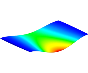
Despite these errors in predicting frequencies, we show in the next section that the flow-added damping can nevertheless be correctly predicted. Moreover, we also present the hydrofoils’ first bending modes in vacuum and in resting fluid, as illustrated in figure 3.
Hydrofoil first bending modes in vacuum and resting fluid: NACA0003's first bending mode in (a) vacuum, (b) resting fluid; F0's first bending mode in (c) vacuum, (d) resting fluid; F1's first bending mode in (e) vacuum, (f) resting fluid; NACA0009 Donaldson's first bending mode in (g) vacuum, (h) resting fluid and NACA0009 blunt's first bending mode in (i) vacuum, (j) resting fluid.

It can be observed from these figures that the mode shapes, if not exactly the same, are very similar, with a difference in amplitude. This can also be observed from the modal assurance criterion (MAC) (Reference Pastor, Binda and HarčarikPastor et al. 2012). Moreover, the order of the modes can vary due to an important variation of natural frequency and therefore need to be matched together when crossing between the vacuum and resting fluid modes. The MAC evaluates the correspondence of two mode shapes such that
 \begin{equation} MA{C}_{i,j} =
\frac{\vert \{\boldsymbol{\phi}_{i,vac}\}^{\rm T} \{\boldsymbol{\phi}_{j,fr} \}
\vert^2}{(\{\boldsymbol{\phi}_{i,vac} \}^{\rm T} \{\boldsymbol{\phi}_{i,vac}\})(\{\boldsymbol{\phi}_{j,fr} \}^{\rm T} \{\boldsymbol{\phi}_{j,fr}
\})}, \end{equation}
\begin{equation} MA{C}_{i,j} =
\frac{\vert \{\boldsymbol{\phi}_{i,vac}\}^{\rm T} \{\boldsymbol{\phi}_{j,fr} \}
\vert^2}{(\{\boldsymbol{\phi}_{i,vac} \}^{\rm T} \{\boldsymbol{\phi}_{i,vac}\})(\{\boldsymbol{\phi}_{j,fr} \}^{\rm T} \{\boldsymbol{\phi}_{j,fr}
\})}, \end{equation}
where  $MA{C}_{i,j}$ is the MAC for the $i$th mode shape in vacuum and $j$th mode shape in resting fluid, $\boldsymbol{\phi} _{i,vac}$ is the $i$th mode shape in vacuum and $\boldsymbol{\phi} _{j,fr}$ is the $j$th mode shape in resting fluid. The value of the MAC is close to zero for non-similar mode shapes and near unity for similar modes scaled differently (Reference Pastor, Binda and HarčarikPastor et al. 2012).
The MAC of the first ten corresponding vacuum–resting fluid modes of the different hydrofoils is presented in table 3, with the mode numbers associated. From table 3, it is observed that the modes in vacuum and resting fluid are mostly similar, although some resting fluid modes tend to deviate from the vacuum modes, especially for the F0 and F1 hydrofoils. For all hydrofoils, the first mode in resting water becomes a rigid body mode with a frequency of around  $10^{-5}$ Hz and, for the F0 and F1 hydrofoils, the second mode in resting water becomes a fluid mode with displacements being $10^{-3}$ times smaller than those of structural modes. However, most of the modes are adequately matched, with the lowest MAC being 0.9653 for the eighth NACA0003 vacuum mode, 0.5572 for the second F0 vacuum mode, 0.6660 for the second F1 vacuum mode, 0.8868 for the sixth NACA0009 Donaldson vacuum mode and 0.8933 for the sixth NACA0009 blunt mode. Therefore, from these analyses, the matrix $[P]$ can be constructed and implemented into the aeroelastic analysis. For the different hydrofoils studied, the ten first $P_i$ terms are detailed in table 4.
Modal assurance criterion between the  $i$th vacuum and $j$th resting fluid mode shapes for the NACA0003, F0, F1, Donaldson and blunt NACA0009 hydrofoils. A value near unity means good correspondence between the two mode shapes.

Ten first AVMI matrix diagonal components for the NACA0003, F0, F1 and NACA0009 hydrofoils.

3.3 Flow-added damping
Once the AVMI matrix is constructed, it is possible to produce the aerodynamic mesh and spline. The aerodynamic spline used here allows NASTRAN to couple the aerodynamic mesh deformation and load with the structural elements. Therefore, the spline is effectively a link between structural mechanics and the modelled aerodynamics (Siemens 2014a). Once again, these meshes are very similar from one hydrofoil to another. Therefore, only the mesh for the NACA0003 is presented in figure 1(d). It is important to note that the aerodynamic mesh is composed of CAERO1 elements in NASTRAN, which are doublet-lattice panels. Therefore, the analysis proposed here is subject to the potential flow hypotheses, such as the absence of viscosity. Here, the mesh and solver parameters are common to all five hydrofoils with 16 chordwise panels, 16 spanwise panels and the use of the first ten modes in (2.13). The chordwise panels are distributed using a cosine distribution while the spanwise panels are distributed evenly.
Once modelled and simulated, the dimensionless natural frequency and dimensionless damping of each hydrofoil can be plotted and compared with experimental and numerical results (Reference Roth, Calmon, Farhat, Münch, Bjoern and AvellanRoth et al. 2009; Reference Cupr, Rudolf and HabánCupr et al. 2018; Reference Bergan, Tengs, Solemslie and DahlhaugBergan et al. 2019a; Reference Zeng, Yao, Zhou, Wang and HongZeng et al. 2019), as is observed in figure 4. Each figure represents the hydrofoil's flow-added damping  $\zeta _{i, added}$ according to the reduced velocity $U_R$ as well as a dimensionless natural frequency $\varOmega _i={f_{i,fr}}/{f_{1,fr}}$, with $f_{i,fr}$ the resting fluid natural frequency of each $i$ mode. The experimental and numerical results are presented along with the results obtained from the methodology proposed. The numerical results obtained from NASTRAN, which are labelled as hydroelastic, can therefore be compared with the literature. We observed very similar trends between the hydroelastic results and the existing data, but a constant difference was observed. This difference is caused by an existing structural damping that is not evaluated by NASTRAN. Therefore, all results from previous articles which present a structural damping, typically seen from a non-zero damping at resting flow velocities, need to be corrected by shifting them to a null $y$-intercept. Here, we only present the shifted data to allow a fair comparison with our results.
Dependence of dimensionless frequency  $\varOmega _i$ and flow-added damping $\zeta _{i,added}$ on the reduced velocity $U_R$ for the first mode of the studied hydrofoils in comparison with the literature: (a,b) NACA0003 (Reference Cupr, Rudolf and HabánCupr et al. 2018); (c,d) F0 (Reference Bergan, Tengs, Solemslie and DahlhaugBergan et al. 2019a); (e,f) F1 (Reference Bergan, Tengs, Solemslie and DahlhaugBergan et al. 2019a): (g,h) NACA0009 Donaldson (Reference Zeng, Yao, Zhou, Wang and HongZeng et al. 2019); (i,j) and NACA0009 blunt (Reference Roth, Calmon, Farhat, Münch, Bjoern and AvellanRoth et al. 2009; Reference Zeng, Yao, Zhou, Wang and HongZeng et al. 2019). The fundamental frequencies used for the dimensionless frequencies $\varOmega _i$ are found in table 2. Experimental and numerical results for the first bending mode, presented as data points, are compared with hydroelastic results, presented as continuous lines. The experimental and numerical added damping results are shifted to account for structural damping. For the F0 and F1 hydrofoils, an estimated vortex shedding frequency is plotted as observed from experimental results (Reference Bergan, Tengs, Solemslie and DahlhaugBergan et al. 2019a).

From figure 4, it is possible to observe good agreement between the first mode obtained by NASTRAN and the data from the literature, especially for the F1 and F0 hydrofoils. This is true for both the flow-added damping and the natural frequency. The F0 hydrofoil presents a certain difference in damping from the literature, while keeping a very similar trend. This difference can be caused by the presence of lock-in (Reference Bergan, Tengs, Solemslie and DahlhaugBergan et al. 2019a) where the added damping slope changes drastically.
This can be observed both for the F0 and F1 hydrofoils where our results reveal two distinct regions: the first occurs prior to lock-in, characterized by nearly constant and negligible damping, while the second region shows a linear increase in damping with flow velocity. This concept was previously observed by Reference Zeng, Wang, Huang, Wang, Xiao and YaoZeng et al. (2023), who introduced a CEE delineating these two distinct regions of flow-added damping. Figure 5 presents the comparison of our results in continuous lines with the CEE from Reference Zeng, Wang, Huang, Wang, Xiao and YaoZeng et al. (2023) in dashed lines. As the reduced velocity is defined with the chord in the CEE, the results of figure 5 are using the same definition of the reduced velocity. Our proposed model and Zeng et al.'s CEE model agree well for the NACA0009 cases and the NACA0003 case. For the F0 and F1 cases, the slope of the empirical equation is smaller than our model which predicted accurately the experimental results. In all cases, the CEE predictions and our results are in the same range, though the CEE always predicts a smaller slope. Note that our model is predictive and is based on geometry and physical quantities without any tuneable parameter.
Dependence of flow-added damping  $\zeta _{i,added}$ on the reduced velocity $U_R$ for the first mode of the studied hydrofoils in comparison with the CEE (Reference Zeng, Wang, Huang, Wang, Xiao and YaoZeng et al. 2023): (a) NACA0003; (b) F0; (c) F1; (d) NACA0009 Donaldson; (e) NACA0009 blunt. The CEE for the first bending mode, presented as dashed lines, is compared with hydroelastic results, presented as continuous lines.

Lock-in is observed when the vortex shedding frequency is equal to the structure's natural frequency, as can be observed in figures 4(c) and 4(e). This difference can be caused by unsteady effects as vortices are shed on the hydrofoil's trailing edge. Simply put, in the lock-in range, the Kutta condition is not respected. Therefore, around the lock-in range, the proposed method does not produce reliable results due to its inability to capture vortices, but it captures regimes outside of the lock-in range. Another important limitation that can be observed is how the hydroelastic method evaluates the added damping at very low reduced velocities, such as in figure 4(d). Indeed, for such low reduced velocities, NASTRAN observes certain instabilities that prevent the method from converging. Therefore, the current methodology is only reliable at high reduced velocities, such that NASTRAN's reduced frequencies stay small. From figures 4(h) and 4(j), we observe that the added damping was a little underestimated compared with the literature, which is logical considering that the hydrofoils have thicker trailing edges and a generally thicker aspect ratio. Indeed, thicker hydrofoils tend to undergo greater unsteady effects through larger vortices shed on the hydrofoil's trailing edge. However, the estimated flow-added damping still gives an idea of the true value of the observed damping and, for the blunt trailing edge NACA0009 in figure 4(j), the general flow-added damping trend is similar. Another error source could be the fact that the boundary conditions are different than previously presented as they are now clamped–free instead of clamped–clamped. This difference of boundary condition will impact the flow-added damping, as a larger amount of fluid is in motion due to larger deformation of the clamped–free hydrofoils. However, here, we believe the greater discrepancy between the flow-added damping of the NACA0009 cases is mostly due to their generally thicker profile and thicker trailing edges. Therefore, it is important to use the current methodology for slender hydrofoils and thin trailing edges, as they experience fewer vortices than thicker hydrofoils. In short, the current methodology is valid for slender hydrofoils in the range of large Reynolds numbers, and large reduced velocities. This ensures small reduced frequencies for NASTRAN, and reduced velocities far from the lock-in range for an irrotational flow. We note that the impact of the inviscid flow hypothesis will have multiple physical effects, such as the inability to capture vortices and boundary layer dynamics, but will also reduce the overall flow-added damping that is evaluated. Viscosity will increase dissipation and therefore increase damping, which will not be captured in our model.
Using the methodology presented, it is also possible to evaluate the flow-added damping of higher-order modes, while keeping low computation times. In figure 6, the dimensionless frequency and dimensionless damping are plotted against the reduced velocity for the five presented hydrofoils, while studying the first three modes of each hydrofoil. As is expected, the dimensionless natural frequencies of the different modes increase, but we can also observe that, according to this method, the flow-added damping decreases for higher-order modes. Most of the literature only covers the first bending mode, validating these results therefore lies outside the scope of this paper.
Dependence of the dimensionless frequency  $\varOmega _i$ and flow-added damping $\zeta _{i,added}$ on the reduced velocity $U_R$ for the first 3 modes of the studied hydrofoils: (a,b) NACA0003; (c,d) F0; (e,f) F1; (g,h) NACA0009 Donaldson trailing edge; (i,j) and NACA0009 blunt trailing edge. The fundamental frequencies used for the dimensionless frequencies $\varOmega _i$ are found in table 2.

Since this method does not rely on RANS simulations, its simulation time is shorter than typically observed with CFD-coupled methods. The different illustrated cases were solved in different amounts of time ranging from 12 to 22 minutes, considering the set-up, writing, solution and analysis time from the custom Python script, while producing results presenting good agreement with existing data. It is important to note that these times could be improved by optimizing the custom Python script, using parallel computing, using a pre-compiled programming language or by upgrading the used machine. These specific times were obtained on a laptop equipped with an Intel Core i7-9750H CPU and 12 G of RAM.
4. Conclusion and further work
Added damping associated with a heavy fluid flowing around a structure is a challenge to compute efficiently. For hydraulic turbines, those computations are important to evaluate the durability of the runner, guide vanes and stay vanes. The present article offers a new, simpler and computationally cheaper method using NASTRAN's modal analysis, vibro-acoustic analysis and aeroelasticity modules to evaluate this added damping with some accuracy. The key to this method is to use an AVMI matrix in the flutter solution of the aeroelasticity module, which is obtained from resting fluid and vacuum modal analyses. When comparing the results of this new method with published results on simple hydrofoils, a good fit between the extracted data and the numerical prediction is obtained.
This method therefore presents very promising and interesting results. However, it is important to note its limitations and restrictions. First, the minimum flow velocity is limited by NASTRAN. Secondly, the fact that the flutter solution used is based on a potential flow approach limits the accuracy of the solution for FSI where viscous effects cannot be neglected. We note that the current methodology's potential is limited by the demonstrated cases. We limited our analyses to hydrofoil geometries obtainable from the literature, which are typically standalone, non-cambered hydrofoils with no angle of attack, twist, sweep angle or confinement. A sweeping angle could be added without any modifications, while the software could be modified to include angles of attack, camber and twist using the available downwash matrix and cascades could be accounted for by coupling the hydrofoil modes together. As for confinement, it would be more difficult to represent numerically. These different cases are currently being addressed by a follow-up project.
Another important aspect in the development of such a methodology is the availability of accurate and detailed experimental data. A comprehensive research effort to evaluate flow-added damping on a model Francis turbine runner is currently underway at the Heki innovation centre of the Université Laval (Reference Châteauvert, Tessier, St-Amant, Nicolle and HoudeChâteauvert et al. 2021). Using a model of a turbine in operation, measurements on a structurally homologous runner are performed, specifically with the goal of quantifying flow-added damping in different operating conditions, including no-load conditions. Our method will have to be adapted to consider the geometrical complexity of a real three-dimensional runner.
In the future, this method could be part of a set of tools to quickly compute the residual life of hydraulic turbines through, for example, stability maps using multiple modes and to implement FSI analyses into the turbines’ design workflow. We could also imagine turbine runner designs optimized to increase the flow-added damping and thus exhibit improved longevity in off-design operations. Such an improvement in runner design would allow a better integration of other clean energy sources complementary to hydroelectric power, such as wind and solar, into the energy grid.
Acknowledgements
This work is supported by the Consortium on Hydraulic Machines (Andritz Hydro, Électricité de France, GE Vernova, Hydro-Québec, Vattenfall, Voith Hydro, Université Laval and École Polytechnique de Montréal), the Natural Sciences and Engineering Research Council of Canada and InnovÉÉ. The authors wish to thank O. Duchesne and D. Lessard for their code templates using Gmsh and pyNastran.
Funding
D.L. acknowledges funding by a Natural Sciences and Engineering Research Council of Canada (NSERC) Undergraduate Student Research Award (USRA). C.A. and O.T.L. acknowledge funding from Institut de l’Énergie Trottier scholarships.
Declaration of interests
The authors declare no conflict of interest.
Data availability statement
All scripts are available on Github at Reference Lamoureux and AudefroyLamoureux & Audefroy (2024).


 Open access