





A correction to the analysis by Frank et al. (2025 J. Plasma Phys. 91, E110) is provided. We correct an error in the root-finding method used to generate the plasma operation and performance contours (POPCONs) that resulted in invalid operating points being generated at which power balance was not satisfied. Our updated analysis corrects this error while retaining otherwise identical methodology and finds new self-consistent operating points. Some parameters of the optimised device change, but the key conclusions by Frank et al. (2025 J. Plasma Phys. 91, E110) remain the same: an end plug using high-temperature superconducting magnets and modern neutral beams enables a classical tandem mirror pilot plant producing a fusion gain Q >5. The tandem mirror pilot plant operating points identified here remain more conservative than others found in the literature with lower temperatures, neutral beam energies and end plug performance requirements.
1. Introduction
The structure of this correction will be as follows. In § 2, we will describe the error in the plasma operation and performance contour (POPCON) root-finding method employed by Frank et al. (Reference Frank2025) and how it was corrected in this analysis. In § 3, we will use corrected POPCONs to repeat the analysis of Frank et al. (Reference Frank2025) to obtain a self-consistent tandem mirror operating point. We will then summarise our conclusions in § 4.
This correction will use the same equations and methodology as used by Frank et al. (Reference Frank2025), and therefore, we will refrain from once again providing the methodology and literature review presented there. We will use identical nomenclature and cite equations from Frank et al. (Reference Frank2025) with schema (N*) where N is the equation number as it appeared in Frank et al. (Reference Frank2025). Similarly, we will refer to sections and figures appearing in Frank et al. (Reference Frank2025) with Section N* and Figure N*.
2. POPCON root-finding error
The root-finding algorithm used by Frank et al. (Reference Frank2025) was MINPACK’s (Moré et al. Reference Moré, Garbow and Hillstrom1980) implementation of Powell’s hybrid algorithm (Powell Reference Powell1970) in SciPy (Virtanen et al. Reference Virtanen2020). The SciPy implementation of this method assesses convergence based on change in relative error between consecutive iterations of the solver rather than assessing the distance of each component of the system of equations from zero. In the absence of valid roots, stable minima in the system of equations can be mistaken for roots.
In the POPCON system of equations (3.1*) for large values of ion-directed central cell auxiliary heating fractions $P_{\text{RF},i}/(P_{\text{RF},e} + P_{\text{RF},i})$
like the value of 80 % used by Frank et al. (Reference Frank2025), solutions to (3.1*) become ill-defined. In this situation, the POPCON’s root-finding algorithm converged, but failed to find valid roots. This was not initially caught because the successful verification of the POPCONs against the results by Fowler, Moir & Simonen (Reference Fowler, Moir and Simonen2017) used an ion-directed RF heating fraction of 0 % (all heating was assumed to come from electron cyclotron heating, ECH). To correct this error and ensure the most stable implementation of the POPCON solver possible, we updated our analysis to assume that all central cell auxiliary heating is electron-directed
$P_{\text{RF},i}/(P_{\text{RF},e} + P_{\text{RF},i})$
like the value of 80 % used by Frank et al. (Reference Frank2025), solutions to (3.1*) become ill-defined. In this situation, the POPCON’s root-finding algorithm converged, but failed to find valid roots. This was not initially caught because the successful verification of the POPCONs against the results by Fowler, Moir & Simonen (Reference Fowler, Moir and Simonen2017) used an ion-directed RF heating fraction of 0 % (all heating was assumed to come from electron cyclotron heating, ECH). To correct this error and ensure the most stable implementation of the POPCON solver possible, we updated our analysis to assume that all central cell auxiliary heating is electron-directed $P_{\text{RF},e}/(P_{\text{RF},e} + P_{\text{RF},i})\sim 1$
. This assumption ensures that (3.1*) always has a valid root, and it can be achieved practically with either an ECH system or a three-ion ion cyclotron minority heating system (ICH) (Kazakov et al. Reference Kazakov2017).
$P_{\text{RF},e}/(P_{\text{RF},e} + P_{\text{RF},i})\sim 1$
. This assumption ensures that (3.1*) always has a valid root, and it can be achieved practically with either an ECH system or a three-ion ion cyclotron minority heating system (ICH) (Kazakov et al. Reference Kazakov2017).
3. An updated tandem mirror operating point
The corrected POPCON analysis indicated that an end plug with $n_p\sim (2.0 \pm 0.5)\times 10^{20}\,\textrm {m}^{-3}$
and
$n_p\sim (2.0 \pm 0.5)\times 10^{20}\,\textrm {m}^{-3}$
and $a_m \sim 0.25\pm 0.05\,\textrm {m}$
would be required to consistently achieve
$a_m \sim 0.25\pm 0.05\,\textrm {m}$
would be required to consistently achieve $Q\gt 5$
for
$Q\gt 5$
for $\ell _c =50\,\mathrm{m}$
and central cell linear power densities comparable to those of Frank et al. (Reference Frank2025):
$\ell _c =50\,\mathrm{m}$
and central cell linear power densities comparable to those of Frank et al. (Reference Frank2025): ${\gt} 5\,\mathrm{MW}\,\mathrm{m}^{-1}$
. The corrected analysis also predicted lower values of
${\gt} 5\,\mathrm{MW}\,\mathrm{m}^{-1}$
. The corrected analysis also predicted lower values of $T_{ec} \sim T_{ic}$
(at fusion-relevant temperatures) and thus lower
$T_{ec} \sim T_{ic}$
(at fusion-relevant temperatures) and thus lower $\phi _e \approx 4{-}5T_e$
. The large
$\phi _e \approx 4{-}5T_e$
. The large $T_e\sim 100\,\mathrm{keV}$
values found by Frank et al. (Reference Frank2025) were a result of the root-finding error. However, in the operating points identified here,
$T_e\sim 100\,\mathrm{keV}$
values found by Frank et al. (Reference Frank2025) were a result of the root-finding error. However, in the operating points identified here, $T_e$
is still somewhat greater than
$T_e$
is still somewhat greater than $T_i$
at
$T_i$
at $T_i \leqslant 50\,\mathrm{keV}$
in spite of the roughly four times larger electron channel energy losses due to strong alpha heating.
$T_i \leqslant 50\,\mathrm{keV}$
in spite of the roughly four times larger electron channel energy losses due to strong alpha heating.
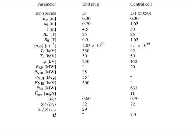
Parameters for the revised optimised end plug and central cell.

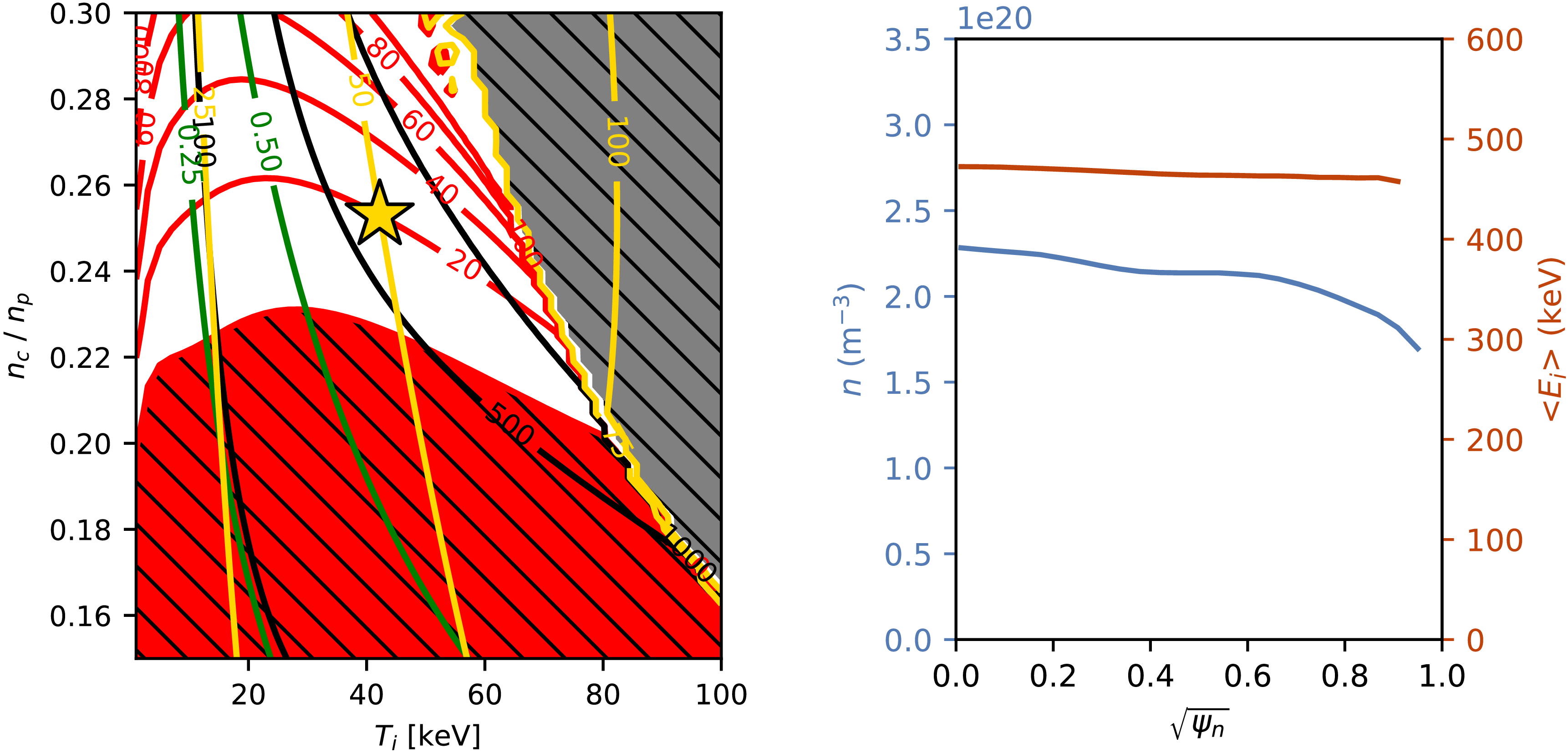
(a) POPCONs for the tandem mirror. Red contours denote supplemental RF heating power in the central cell in MW. Black contours denote the fusion power in the central cell in MW. Green contours denote the plasma $\beta$
. The hatched regions in red and grey are disallowed operating regions where the central cell is ignited (red) or has a value of
$\beta$
. The hatched regions in red and grey are disallowed operating regions where the central cell is ignited (red) or has a value of $\beta \gt 1$
(grey). The operating point shown in table 1 is denoted with a star. (b) Profiles in the tandem mirror end plug calculated by RealTwin simulations and assumed when generating the POPCONs. Density
$\beta \gt 1$
(grey). The operating point shown in table 1 is denoted with a star. (b) Profiles in the tandem mirror end plug calculated by RealTwin simulations and assumed when generating the POPCONs. Density $n$
(blue) and ion energy
$n$
(blue) and ion energy $\langle E_i\rangle$
(red) are plotted versus the square root of the normalised poloidal flux
$\langle E_i\rangle$
(red) are plotted versus the square root of the normalised poloidal flux $\sqrt {\psi _n}$
.
$\sqrt {\psi _n}$
.

Repeating the Bayesian optimisation technique and RealTwin simulations as done by Frank et al. (Reference Frank2025) in § 4* once again yielded an operating point with self-consistent high-fidelity end plug simulation and central cell POPCON parameters. RealTwin simulations optimised end plug conditions over parameter ranges: $a_m = 0.2{-}0.3\,\textrm {m}$
,
$a_m = 0.2{-}0.3\,\textrm {m}$
, $B_m = 25\,\mathrm{T}$
,
$B_m = 25\,\mathrm{T}$
, $B_0 = 6.0{-}8.0\,\mathrm{T}$
,
$B_0 = 6.0{-}8.0\,\mathrm{T}$
, $\ell _p = 4.5\,\mathrm{m}$
,
$\ell _p = 4.5\,\mathrm{m}$
, $E_{\mathrm{NBI}} = 300{-}500\,\mathrm{keV}$
and
$E_{\mathrm{NBI}} = 300{-}500\,\mathrm{keV}$
and $P_{\text{NBI}} = 20{-}40\,\mathrm{MW}$
. This optimisation process combined with standalone self-consistent runs identified the parameters shown in table 1, the POPCONs in figure 1(a) and the simulated end plug profiles shown in figure 1(b). The set-up of these simulations was identical to that of Frank et al. (Reference Frank2025) in § 4* with the exception of the previously noted change in parameter ranges and a change in the ML library used for the backend (we used BoTorch (Balandat et al. Reference Balandat, Karrer, Jiang, Daulton, Letham, Wilson and Bakshy2020) rather than Scikit-learn (Pedregosa et al. Reference Pedregosa2011) here as it provided better computational performance). The optimisation identified an optimum at
$P_{\text{NBI}} = 20{-}40\,\mathrm{MW}$
. This optimisation process combined with standalone self-consistent runs identified the parameters shown in table 1, the POPCONs in figure 1(a) and the simulated end plug profiles shown in figure 1(b). The set-up of these simulations was identical to that of Frank et al. (Reference Frank2025) in § 4* with the exception of the previously noted change in parameter ranges and a change in the ML library used for the backend (we used BoTorch (Balandat et al. Reference Balandat, Karrer, Jiang, Daulton, Letham, Wilson and Bakshy2020) rather than Scikit-learn (Pedregosa et al. Reference Pedregosa2011) here as it provided better computational performance). The optimisation identified an optimum at $a_m=0.3\,\mathrm{m}$
,
$a_m=0.3\,\mathrm{m}$
, $B_0 = 6.5\,\mathrm{T}$
,
$B_0 = 6.5\,\mathrm{T}$
, $P_{\mathrm{NBI}}=35\,\mathrm{MW}$
. This operating point is slightly larger and has a higher central cell mirror ratio than the original operating point identified by Frank et al. (Reference Frank2025), but otherwise is similar to it. The slightly higher central cell mirror ratio does increase the risk of trapped particle modes and this must be addressed in future design studies. POPCON analysis indicated that the performance benefit of moving to
$P_{\mathrm{NBI}}=35\,\mathrm{MW}$
. This operating point is slightly larger and has a higher central cell mirror ratio than the original operating point identified by Frank et al. (Reference Frank2025), but otherwise is similar to it. The slightly higher central cell mirror ratio does increase the risk of trapped particle modes and this must be addressed in future design studies. POPCON analysis indicated that the performance benefit of moving to $P_{\mathrm{NBI}} =40\,\mathrm{MW}$
from
$P_{\mathrm{NBI}} =40\,\mathrm{MW}$
from $35\,\mathrm{MW}$
was marginal and the lower recirculating power solution was favoured. Furthermore, at higher
$35\,\mathrm{MW}$
was marginal and the lower recirculating power solution was favoured. Furthermore, at higher $P_{\mathrm{NBI}}$
, the plasma was more susceptible to a radial profile instability described in § 4* in which
$P_{\mathrm{NBI}}$
, the plasma was more susceptible to a radial profile instability described in § 4* in which $\beta$
rapidly grows on axis due to the NBI power deposition profile. If this instability can be mitigated in future self-consistent simulations with more careful NBI aiming and power/energy modulation, greater plug performance may be obtainable. The POPCON analysis here indicates that
$\beta$
rapidly grows on axis due to the NBI power deposition profile. If this instability can be mitigated in future self-consistent simulations with more careful NBI aiming and power/energy modulation, greater plug performance may be obtainable. The POPCON analysis here indicates that $Q$
is insensitive to applied heating power if density is varied commensurately. This implies that as long as the stabilisation actuators necessary for axisymmetrisation have acceptable wall plug efficiency, they will not substantially impact the viability of the operating point. If higher NBI energies are obtainable, it may be possible to operate at slightly higher
$Q$
is insensitive to applied heating power if density is varied commensurately. This implies that as long as the stabilisation actuators necessary for axisymmetrisation have acceptable wall plug efficiency, they will not substantially impact the viability of the operating point. If higher NBI energies are obtainable, it may be possible to operate at slightly higher $T_e$
and
$T_e$
and $Q$
, but
$Q$
, but $E_{\mathrm{NBI}} \gt 600\,\mathrm{keV}$
provided little performance benefit in exploratory simulations as the shine-through fraction became large.
$E_{\mathrm{NBI}} \gt 600\,\mathrm{keV}$
provided little performance benefit in exploratory simulations as the shine-through fraction became large.
4. Conclusions
We have presented a corrected tandem mirror operating point here using the POPCON solver from Frank et al. (Reference Frank2025) with a correction to its root-finding algorithm. The plug plasma density and neutral beam power are higher and the central cell is somewhat larger than those of Frank et al. (Reference Frank2025), but the original conclusions hold. It is possible to obtain conservative tandem mirror operating points that satisfy $Q\gt 5$
while using lower
$Q\gt 5$
while using lower $E_{\mathrm{NBI}}$
than previous designs and operating with
$E_{\mathrm{NBI}}$
than previous designs and operating with $\beta$
substantially below 1. This is enabled by advances in magnet technology and axisymmetrisation, but also by higher plasma density central cell operation than in early classical tandem mirror design studies, above the central cell ignition threshold. Higher density drives increased fusion power density and therefore alpha heating that can offset electron channel losses.
$\beta$
substantially below 1. This is enabled by advances in magnet technology and axisymmetrisation, but also by higher plasma density central cell operation than in early classical tandem mirror design studies, above the central cell ignition threshold. Higher density drives increased fusion power density and therefore alpha heating that can offset electron channel losses.
 β
β β>1
β>1 n
n ⟨Ei⟩
⟨Ei⟩ ψn
ψn
 Open access

