1. Introduction
The oldest forms of flow control, such as redirecting rivers and building aqueducts and dams, go back millennia and involved flow phenomena at large scales. For modern aerodynamics applications (Joslin Reference Joslin1998), flow control has focused on using sensing and actuation methods (Corke, Enloe & Wilkinson Reference Corke, Enloe and Wilkinson2010; Cattafesta & Sheplak Reference Cattafesta and Sheplak2011) at relatively small, aircraft-boundary-layer scales. Conversely, recent developments in renewable energy, specifically wind energy harvesting, have opened up a new arena for flow control, again at very large scales. Modern utility-scale wind turbines have blades with chord lengths approaching tens of metres, rotor diameters in a range of 100–200 m and they are immersed in the atmospheric boundary layer whose height is of the order of a kilometre. Turbine wakes can affect downstream turbines for several kilometres, and when many turbines are combined in a wind farm array, they can affect other wind farms tens of kilometres downwind. Hence, wind turbines can affect flow conditions over a vast range of scales, from metres to many kilometres. A question then arises: can wind turbines themselves be used as actuators, as part of flow control at very large scales, aiming to enhance power production or reduce turbine wear and tear? Turbine yawing to purposefully steer wakes away from downstream turbines provides an opportunity to do just that.
The possibility of wake steering was pointed out some time ago (Medici & Dahlberg Reference Medici and Dahlberg2003) and has generated considerable interest ever since. The idea is to turn (yaw) a wind turbine so it would not directly face the wind, but would be rotated at some (small) angle with respect to the incoming mean flow direction. Such a configuration creates a net aerodynamic force that is no longer purely in the same (axial) direction as the incoming wind but contains a component in a direction transverse to the incoming wind direction. Even at the cost of reduced power production by the yawed turbine itself, a redirected wake may avoid downstream turbines, boosting combined power production. Accurate modelling is crucial for developing model-based control methods to achieve desired optimal operating conditions. However, a comprehensive understanding and accurate modelling of the fluid mechanics underlying wake deflection and modification of wake shape and its evolution has only recently begun to emerge, with considerable impact from the work of Bastankhah & Porté-Agel (Reference Bastankhah and Porté-Agel2016). We provide an overview of that contribution and highlight some subsequent recent works that have been motivated and influenced by the findings of that paper.
2. Flow structure of yawed wind turbine wakes
As summarized in Bastankhah & Porté-Agel (Reference Bastankhah and Porté-Agel2016), a number of earlier efforts using wind tunnel experiments (Medici & Alfredsson Reference Medici and Alfredsson2006; Howland et al. Reference Howland, Bossuyt, Martínez-Tossas, Meyers and Meneveau2016) and large-eddy simulations (LES) (Jiménez, Crespo & Migoya Reference Jiménez, Crespo and Migoya2010; Fleming et al. Reference Fleming, Gebraad, Lee, van Wingerden, Johnson, Churchfield, Michalakes, Spalart and Moriarty2014) had established the technical feasibility of redirecting wind turbine wakes by yawing a turbine. Prior efforts mostly focused on the near-rotor flow characteristics while experimental wind tunnel measurements considered the case of uniform, non-turbulent inflow. The study of Howland et al. (Reference Howland, Bossuyt, Martínez-Tossas, Meyers and Meneveau2016) quantified wake deflection and deformation in a uniform non-turbulent inflow, using an actuator disk model without including angular momentum in the wake. Background turbulence can significantly affect the evolution of turbulent wakes behind any type of object, increasing diffusion and weakening angular velocities in the wake. What was needed then were experimental studies of wake deflection when a yawed turbine is placed in a turbulent boundary layer representing more realistic atmospheric conditions, and using turbine models with rotating blades to include effects of angular momentum. Responding to this need, the paper of Bastankhah & Porté-Agel (Reference Bastankhah and Porté-Agel2016) reported results from detailed experiments in a large wind tunnel under well-controlled conditions and presented analysis of the measurements aiming to elucidate the underlying physics and explore modelling implications.
The tunnel had a large 24 m long test section, accommodating measurements far downstream at locations at which a thick turbulent boundary layer had developed. A three-bladed miniature model turbine was placed in this boundary layer. The turbine diameter was  $d=15$ cm and the hub height was 12.5 cm at a location where the boundary layer thickness was approximately 40 cm. The turbine was designed to mimic major aerodynamic parameters at the much reduced Reynolds numbers possible in a wind tunnel, as confirmed using measurements of thrust and power coefficients as a function of tip-speed ratio (see figure 2 of Bastankhah & Porté-Agel (Reference Bastankhah and Porté-Agel2016)). The model rotor was attached to a small DC generator with the ability to vary the load and thus select a desired tip-speed ratio. Reported measurement results focused on optimal conditions, in which the electric load was adjusted so as to have the turbine rotating at the optimal tip-speed ratio. Turbulence measurements were performed using stereo particle image velocimetry in a number of planes covering the wake of the turbine. The mean wind speed was held constant, with hub-height velocity of 4.88 m s$^{-1}$, and the model turbine was placed with four different orientations: one without yaw and three with yaw, i.e. with yaw angles $\gamma =0^{\circ }, 10^{\circ }, 20^{\circ }$ and $30^{\circ }$. The yaw angle $\gamma$ is the angle between the incoming wind direction and the turbine rotation axis or unit normal vector to the rotor disk.
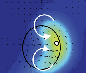
The paper's main experimental results are reproduced in figures 1 and 2. The first shows the mean velocity distribution at hub height on a horizontal plane, and the second shows the mean velocity deficit on planes normal to the mean flow for the case $\gamma = 30^{\circ }$. The lateral displacement of the wake for increasing yaw angle is immediately apparent. Also shown as solid white lines in figure 1 are predictions from an earlier model, overestimating the deflection, and motivating the development of improved models. Fluid mechanically, an initial understanding of the mechanism for the deflection is that the force exerted by the yawed turbine on the passing flow has now a transverse component, causing a sideways deflection. The flow structure that becomes visible in figure 2 hints at the origin of the wake deflection: a pair of counter-rotating streamwise vortices, one above and one below the rotor disk, is generated by the yawed turbine. These results confirm that such vortices are generated and persist downstream even in the strongly turbulent background environment typical of atmospheric conditions.
Figure 1. Wind tunnel measurements of hub-height plane mean velocity distributions in the wake of a turbine yawed at different angles, from the paper of Bastankhah & Porté-Agel (Reference Bastankhah and Porté-Agel2016) (figure 3). The deflection (white dotted line indicates the measured centreline) increases with increasing yaw angle. Solid lines are predictions from earlier wake centreline deflection models.
Figure 2. Measurements of streamwise velocity deficit normalized by hub-height velocity at various downstream locations $x$ normalized by turbine diameter $d$ of a model wind turbine yawed at an angle of $30^{\circ }$, adapted from the paper of Bastankhah & Porté-Agel (Reference Bastankhah and Porté-Agel2016) (figure 5). The black circles indicate the location of the wind turbine and the white dot represents the wake centre at each downwind location. The vectors show in-plane velocity distributions. White arrows indicate the sense of rotation of the inferred CVP on top and bottom of the turbine location.
Bastankhah & Porté-Agel (Reference Bastankhah and Porté-Agel2016) go on to propose a qualitative mechanism for the presence of these streamwise vortices. The yawed turbine generates a sideways force which, based on the transverse momentum equation, should naturally induce a transverse velocity responsible for the transverse wake deflection. Since the velocity reduces in magnitude along the transverse direction away from the turbine, the continuity equation naturally implies that there will be a vertical velocity to account for the changing transverse velocity, consistent with the velocity field as if induced by a pair of vortices. The authors go on to show that a point-vortex model (including image vortices to account for ground effects) can explain several features of the downstream evolution of the counter-rotating vortex pair (CVP). The paper continues and shows that in the far wake the spanwise momentum equation integrated across the wake can be used to develop a transport equation for the wake deflection. When integrated, the result describes the wake lateral displacement. Combined with the authors’ earlier Gaussian wake model (Bastankhah & Porté-Agel Reference Bastankhah and Porté-Agel2014) with distinct wake widths in the horizontal and spanwise directions that increase linearly with downstream distance, a practical wake deflection prediction tool was developed.
3. Impact and follow-up studies
The measurements and confirmation of the existence of a CVP in a turbulent background environment, along with the wake deflection model of Bastankhah & Porté-Agel (Reference Bastankhah and Porté-Agel2016), led to a significant number of follow-up studies. While they cannot be reviewed exhaustively in this short retrospective article, a sample of such works, at least those well known to the author, is provided below.
The possibility of using turbine yaw-induced wake deflection to affect power production has been demonstrated at full scale in several field studies. Field experiments on pairwise interactions between turbines in a wind farm in the US Western Plains region were reported in Fleming et al. (Reference Fleming2019) and Simley et al. (Reference Simley, Fleming, Girard, Alloin, Godefroy and Duc2021), field experimental measurements of the wake in a yawed turbine at the Danish Technical University's Risoe test site were reported in Larsen et al. (Reference Larsen, Ott, Liew, van der Laan, Simon, Thorsen and Jacobs2020), while Howland, Lele & Dabiri (Reference Howland, Lele and Dabiri2019) reported increased total power production at a six-turbine wind farm in Canada. In order to decide on specific yaw angles for each turbine, wake models including its deflection are needed for optimization. The field campaign of Fleming et al. (Reference Fleming2019) and Simley et al. (Reference Simley, Fleming, Girard, Alloin, Godefroy and Duc2021) used models in the Flow Redirection and Induction in Steady State (FLORIS) software which incorporated, among others, the wake deflection model introduced in Bastankhah & Porté-Agel (Reference Bastankhah and Porté-Agel2016).
As mentioned before, a turbine yawed in relation to the incoming wind generates a transverse aerodynamic force which induces transverse motion and a CVP. For models, the challenge of predicting the magnitude of the transverse velocity based on knowledge of the transverse force and using the momentum equation is that it requires knowledge of the induced pressure field. Instead of focusing on the transverse momentum equation, prediction of streamwise vorticity generation due to vertical variations in the transverse force can be done without having to include the pressure field which is difficult to determine. Focusing on the vorticity generation (or shed circulation), classical lifting line theory can be applied to this problem (Shapiro, Gayme & Meneveau Reference Shapiro, Gayme and Meneveau2018). Moreover, one recognizes that a circular distribution of transverse (lift, sideways) forces can be viewed as a special case of an elliptical distribution of circulation, akin to an elliptical wing. This realization can be used to predict the strength (circulation) of the induced CVP as well as the initial transverse velocity magnitude. The predicted wake displacement was used by Shapiro et al. (Reference Shapiro, Gayme and Meneveau2018) in conjunction with the Gaussian wake model of Bastankhah & Porté-Agel (Reference Bastankhah and Porté-Agel2014) to reproduce velocity distributions that agreed very well with the data shown in figure 1. The large-scale field study of Howland et al. (Reference Howland, Lele and Dabiri2019) used this approach coupled with several other model ingredients in their determination of optimal turbine yaw.
Many additional detailed studies of the flow structure in wakes of yawed wind turbines have taken place. For instance, Li & Yang (Reference Li and Yang2021) used a series of detailed LES to evaluate possible scalings of downstream profiles of streamwise and transverse velocity, as well as Reynolds stresses and various other flow characteristics. Ciri, Rotea & Leonardi (Reference Ciri, Rotea and Leonardi2018) used LES to quantify effects of turbine scale and control methodology, as well as to study the unsteady loading implications of wake steering. The evolution and downstream decay of the streamwise CVP have been studied using LES in neutral boundary layers (Shapiro, Gayme & Meneveau Reference Shapiro, Gayme and Meneveau2020) as well as in more realistic atmospheric boundary layers with veer (Narasimhan, Gayme & Meneveau Reference Narasimhan, Gayme and Meneveau2022). The measurement results of Bastankhah & Porté-Agel (Reference Bastankhah and Porté-Agel2016) have also influenced a number of further analytical wake modelling efforts. For instance, a curled wake model based on numerically advecting vortex elements was developed by Martínez-Tossas et al. (Reference Martínez-Tossas, Annoni, Fleming and Churchfield2019), while Bastankhah et al. (Reference Bastankhah, Shapiro, Shamsoddin, Gayme and Meneveau2022) proposed replacing the lifting line with a vortex cylinder method that enabled predicting the entire wake shape deformation including curled shapes such as those in figure 2. Heck, Johlas & Howland (Reference Heck, Johlas and Howland2023) introduced a model based on extended one-dimensional momentum theory coupled to the lifting line prediction of spanwise velocity disturbance.
4. Future perspectives
Various future extensions of these studies come to mind. Turbine tilting (front–back inclination of the rotor disk) is already being considered in a number of recent works (Bossuyt et al. Reference Bossuyt, Scott, Ali and Cal2021; Johlas, Schmidt & Lackner Reference Johlas, Schmidt and Lackner2022). By analogy, tilting creates a CVP on either side of the turbine, generating vertical induced velocities that deflect the wake vertically instead of sideways. Unlike yawing, a traditional horizontal-axis wind turbine cannot be tilted up and down. However, offshore turbines mounted on floating platforms are expected to be exposed to tilting motions due to the passage of waves. Offshore wind energy applications motivate many further extensions, especially the need for better models under common conditions of strong stable thermal stratification of the marine atmospheric boundary layer. This article has focused on the steady-state wake structure that requires some time to establish itself. For control purposes, dynamic models that enable description of the time evolution of yawing turbine wakes are necessary and are being developed (Ciri et al. Reference Ciri, Rotea and Leonardi2018; King et al. Reference King, Fleming, King, Martínez-Tossas, Bay, Mudafort and Simley2021; Becker et al. Reference Becker, Ritter, Doekemeijer, van der Hoek, Konigorski, Allaerts and van Wingerden2022; Starke et al. Reference Starke, Meneveau, King and Gayme2023). Further refinements and increased accuracy of such models are another important area of ongoing research. Moreover, additional field measurement campaigns under realistic atmospheric conditions with advanced measurement tools such as those in Brugger et al. (Reference Brugger2020) and Silverstein et al. (Reference Silverstein, Lundquist, Debnath, Simley and Rybchuk2024) will further benefit these studies.
In summary, following the work of Bastankhah & Porté-Agel (Reference Bastankhah and Porté-Agel2016) and others, there is an improved but still evolving understanding of the flow structure induced by misaligned wind turbines. Such understanding is critical to enable effective flow control at very large scales.


 Open access
1. Introduction
The oldest forms of flow control, such as redirecting rivers and building aqueducts and dams, go back millennia and involved flow phenomena at large scales. For modern aerodynamics applications (Joslin Reference Joslin1998), flow control has focused on using sensing and actuation methods (Corke, Enloe & Wilkinson Reference Corke, Enloe and Wilkinson2010; Cattafesta & Sheplak Reference Cattafesta and Sheplak2011) at relatively small, aircraft-boundary-layer scales. Conversely, recent developments in renewable energy, specifically wind energy harvesting, have opened up a new arena for flow control, again at very large scales. Modern utility-scale wind turbines have blades with chord lengths approaching tens of metres, rotor diameters in a range of 100–200 m and they are immersed in the atmospheric boundary layer whose height is of the order of a kilometre. Turbine wakes can affect downstream turbines for several kilometres, and when many turbines are combined in a wind farm array, they can affect other wind farms tens of kilometres downwind. Hence, wind turbines can affect flow conditions over a vast range of scales, from metres to many kilometres. A question then arises: can wind turbines themselves be used as actuators, as part of flow control at very large scales, aiming to enhance power production or reduce turbine wear and tear? Turbine yawing to purposefully steer wakes away from downstream turbines provides an opportunity to do just that.
The possibility of wake steering was pointed out some time ago (Medici & Dahlberg Reference Medici and Dahlberg2003) and has generated considerable interest ever since. The idea is to turn (yaw) a wind turbine so it would not directly face the wind, but would be rotated at some (small) angle with respect to the incoming mean flow direction. Such a configuration creates a net aerodynamic force that is no longer purely in the same (axial) direction as the incoming wind but contains a component in a direction transverse to the incoming wind direction. Even at the cost of reduced power production by the yawed turbine itself, a redirected wake may avoid downstream turbines, boosting combined power production. Accurate modelling is crucial for developing model-based control methods to achieve desired optimal operating conditions. However, a comprehensive understanding and accurate modelling of the fluid mechanics underlying wake deflection and modification of wake shape and its evolution has only recently begun to emerge, with considerable impact from the work of Bastankhah & Porté-Agel (Reference Bastankhah and Porté-Agel2016). We provide an overview of that contribution and highlight some subsequent recent works that have been motivated and influenced by the findings of that paper.
2. Flow structure of yawed wind turbine wakes
As summarized in Bastankhah & Porté-Agel (Reference Bastankhah and Porté-Agel2016), a number of earlier efforts using wind tunnel experiments (Medici & Alfredsson Reference Medici and Alfredsson2006; Howland et al. Reference Howland, Bossuyt, Martínez-Tossas, Meyers and Meneveau2016) and large-eddy simulations (LES) (Jiménez, Crespo & Migoya Reference Jiménez, Crespo and Migoya2010; Fleming et al. Reference Fleming, Gebraad, Lee, van Wingerden, Johnson, Churchfield, Michalakes, Spalart and Moriarty2014) had established the technical feasibility of redirecting wind turbine wakes by yawing a turbine. Prior efforts mostly focused on the near-rotor flow characteristics while experimental wind tunnel measurements considered the case of uniform, non-turbulent inflow. The study of Howland et al. (Reference Howland, Bossuyt, Martínez-Tossas, Meyers and Meneveau2016) quantified wake deflection and deformation in a uniform non-turbulent inflow, using an actuator disk model without including angular momentum in the wake. Background turbulence can significantly affect the evolution of turbulent wakes behind any type of object, increasing diffusion and weakening angular velocities in the wake. What was needed then were experimental studies of wake deflection when a yawed turbine is placed in a turbulent boundary layer representing more realistic atmospheric conditions, and using turbine models with rotating blades to include effects of angular momentum. Responding to this need, the paper of Bastankhah & Porté-Agel (Reference Bastankhah and Porté-Agel2016) reported results from detailed experiments in a large wind tunnel under well-controlled conditions and presented analysis of the measurements aiming to elucidate the underlying physics and explore modelling implications.
The tunnel had a large 24 m long test section, accommodating measurements far downstream at locations at which a thick turbulent boundary layer had developed. A three-bladed miniature model turbine was placed in this boundary layer. The turbine diameter was $d=15$ cm and the hub height was 12.5 cm at a location where the boundary layer thickness was approximately 40 cm. The turbine was designed to mimic major aerodynamic parameters at the much reduced Reynolds numbers possible in a wind tunnel, as confirmed using measurements of thrust and power coefficients as a function of tip-speed ratio (see figure 2 of Bastankhah & Porté-Agel (Reference Bastankhah and Porté-Agel2016)). The model rotor was attached to a small DC generator with the ability to vary the load and thus select a desired tip-speed ratio. Reported measurement results focused on optimal conditions, in which the electric load was adjusted so as to have the turbine rotating at the optimal tip-speed ratio. Turbulence measurements were performed using stereo particle image velocimetry in a number of planes covering the wake of the turbine. The mean wind speed was held constant, with hub-height velocity of 4.88 m s $^{-1}$, and the model turbine was placed with four different orientations: one without yaw and three with yaw, i.e. with yaw angles $\gamma =0^{\circ }, 10^{\circ }, 20^{\circ }$ and $30^{\circ }$. The yaw angle $\gamma$ is the angle between the incoming wind direction and the turbine rotation axis or unit normal vector to the rotor disk.
The paper's main experimental results are reproduced in figures 1 and 2. The first shows the mean velocity distribution at hub height on a horizontal plane, and the second shows the mean velocity deficit on planes normal to the mean flow for the case $\gamma = 30^{\circ }$. The lateral displacement of the wake for increasing yaw angle is immediately apparent. Also shown as solid white lines in figure 1 are predictions from an earlier model, overestimating the deflection, and motivating the development of improved models. Fluid mechanically, an initial understanding of the mechanism for the deflection is that the force exerted by the yawed turbine on the passing flow has now a transverse component, causing a sideways deflection. The flow structure that becomes visible in figure 2 hints at the origin of the wake deflection: a pair of counter-rotating streamwise vortices, one above and one below the rotor disk, is generated by the yawed turbine. These results confirm that such vortices are generated and persist downstream even in the strongly turbulent background environment typical of atmospheric conditions.
Figure 1. Wind tunnel measurements of hub-height plane mean velocity distributions in the wake of a turbine yawed at different angles, from the paper of Bastankhah & Porté-Agel (Reference Bastankhah and Porté-Agel2016) (figure 3). The deflection (white dotted line indicates the measured centreline) increases with increasing yaw angle. Solid lines are predictions from earlier wake centreline deflection models.
Figure 2. Measurements of streamwise velocity deficit normalized by hub-height velocity at various downstream locations $x$ normalized by turbine diameter $d$ of a model wind turbine yawed at an angle of $30^{\circ }$, adapted from the paper of Bastankhah & Porté-Agel (Reference Bastankhah and Porté-Agel2016) (figure 5). The black circles indicate the location of the wind turbine and the white dot represents the wake centre at each downwind location. The vectors show in-plane velocity distributions. White arrows indicate the sense of rotation of the inferred CVP on top and bottom of the turbine location.
Bastankhah & Porté-Agel (Reference Bastankhah and Porté-Agel2016) go on to propose a qualitative mechanism for the presence of these streamwise vortices. The yawed turbine generates a sideways force which, based on the transverse momentum equation, should naturally induce a transverse velocity responsible for the transverse wake deflection. Since the velocity reduces in magnitude along the transverse direction away from the turbine, the continuity equation naturally implies that there will be a vertical velocity to account for the changing transverse velocity, consistent with the velocity field as if induced by a pair of vortices. The authors go on to show that a point-vortex model (including image vortices to account for ground effects) can explain several features of the downstream evolution of the counter-rotating vortex pair (CVP). The paper continues and shows that in the far wake the spanwise momentum equation integrated across the wake can be used to develop a transport equation for the wake deflection. When integrated, the result describes the wake lateral displacement. Combined with the authors’ earlier Gaussian wake model (Bastankhah & Porté-Agel Reference Bastankhah and Porté-Agel2014) with distinct wake widths in the horizontal and spanwise directions that increase linearly with downstream distance, a practical wake deflection prediction tool was developed.
3. Impact and follow-up studies
The measurements and confirmation of the existence of a CVP in a turbulent background environment, along with the wake deflection model of Bastankhah & Porté-Agel (Reference Bastankhah and Porté-Agel2016), led to a significant number of follow-up studies. While they cannot be reviewed exhaustively in this short retrospective article, a sample of such works, at least those well known to the author, is provided below.
The possibility of using turbine yaw-induced wake deflection to affect power production has been demonstrated at full scale in several field studies. Field experiments on pairwise interactions between turbines in a wind farm in the US Western Plains region were reported in Fleming et al. (Reference Fleming2019) and Simley et al. (Reference Simley, Fleming, Girard, Alloin, Godefroy and Duc2021), field experimental measurements of the wake in a yawed turbine at the Danish Technical University's Risoe test site were reported in Larsen et al. (Reference Larsen, Ott, Liew, van der Laan, Simon, Thorsen and Jacobs2020), while Howland, Lele & Dabiri (Reference Howland, Lele and Dabiri2019) reported increased total power production at a six-turbine wind farm in Canada. In order to decide on specific yaw angles for each turbine, wake models including its deflection are needed for optimization. The field campaign of Fleming et al. (Reference Fleming2019) and Simley et al. (Reference Simley, Fleming, Girard, Alloin, Godefroy and Duc2021) used models in the Flow Redirection and Induction in Steady State (FLORIS) software which incorporated, among others, the wake deflection model introduced in Bastankhah & Porté-Agel (Reference Bastankhah and Porté-Agel2016).
As mentioned before, a turbine yawed in relation to the incoming wind generates a transverse aerodynamic force which induces transverse motion and a CVP. For models, the challenge of predicting the magnitude of the transverse velocity based on knowledge of the transverse force and using the momentum equation is that it requires knowledge of the induced pressure field. Instead of focusing on the transverse momentum equation, prediction of streamwise vorticity generation due to vertical variations in the transverse force can be done without having to include the pressure field which is difficult to determine. Focusing on the vorticity generation (or shed circulation), classical lifting line theory can be applied to this problem (Shapiro, Gayme & Meneveau Reference Shapiro, Gayme and Meneveau2018). Moreover, one recognizes that a circular distribution of transverse (lift, sideways) forces can be viewed as a special case of an elliptical distribution of circulation, akin to an elliptical wing. This realization can be used to predict the strength (circulation) of the induced CVP as well as the initial transverse velocity magnitude. The predicted wake displacement was used by Shapiro et al. (Reference Shapiro, Gayme and Meneveau2018) in conjunction with the Gaussian wake model of Bastankhah & Porté-Agel (Reference Bastankhah and Porté-Agel2014) to reproduce velocity distributions that agreed very well with the data shown in figure 1. The large-scale field study of Howland et al. (Reference Howland, Lele and Dabiri2019) used this approach coupled with several other model ingredients in their determination of optimal turbine yaw.
Many additional detailed studies of the flow structure in wakes of yawed wind turbines have taken place. For instance, Li & Yang (Reference Li and Yang2021) used a series of detailed LES to evaluate possible scalings of downstream profiles of streamwise and transverse velocity, as well as Reynolds stresses and various other flow characteristics. Ciri, Rotea & Leonardi (Reference Ciri, Rotea and Leonardi2018) used LES to quantify effects of turbine scale and control methodology, as well as to study the unsteady loading implications of wake steering. The evolution and downstream decay of the streamwise CVP have been studied using LES in neutral boundary layers (Shapiro, Gayme & Meneveau Reference Shapiro, Gayme and Meneveau2020) as well as in more realistic atmospheric boundary layers with veer (Narasimhan, Gayme & Meneveau Reference Narasimhan, Gayme and Meneveau2022). The measurement results of Bastankhah & Porté-Agel (Reference Bastankhah and Porté-Agel2016) have also influenced a number of further analytical wake modelling efforts. For instance, a curled wake model based on numerically advecting vortex elements was developed by Martínez-Tossas et al. (Reference Martínez-Tossas, Annoni, Fleming and Churchfield2019), while Bastankhah et al. (Reference Bastankhah, Shapiro, Shamsoddin, Gayme and Meneveau2022) proposed replacing the lifting line with a vortex cylinder method that enabled predicting the entire wake shape deformation including curled shapes such as those in figure 2. Heck, Johlas & Howland (Reference Heck, Johlas and Howland2023) introduced a model based on extended one-dimensional momentum theory coupled to the lifting line prediction of spanwise velocity disturbance.
4. Future perspectives
Various future extensions of these studies come to mind. Turbine tilting (front–back inclination of the rotor disk) is already being considered in a number of recent works (Bossuyt et al. Reference Bossuyt, Scott, Ali and Cal2021; Johlas, Schmidt & Lackner Reference Johlas, Schmidt and Lackner2022). By analogy, tilting creates a CVP on either side of the turbine, generating vertical induced velocities that deflect the wake vertically instead of sideways. Unlike yawing, a traditional horizontal-axis wind turbine cannot be tilted up and down. However, offshore turbines mounted on floating platforms are expected to be exposed to tilting motions due to the passage of waves. Offshore wind energy applications motivate many further extensions, especially the need for better models under common conditions of strong stable thermal stratification of the marine atmospheric boundary layer. This article has focused on the steady-state wake structure that requires some time to establish itself. For control purposes, dynamic models that enable description of the time evolution of yawing turbine wakes are necessary and are being developed (Ciri et al. Reference Ciri, Rotea and Leonardi2018; King et al. Reference King, Fleming, King, Martínez-Tossas, Bay, Mudafort and Simley2021; Becker et al. Reference Becker, Ritter, Doekemeijer, van der Hoek, Konigorski, Allaerts and van Wingerden2022; Starke et al. Reference Starke, Meneveau, King and Gayme2023). Further refinements and increased accuracy of such models are another important area of ongoing research. Moreover, additional field measurement campaigns under realistic atmospheric conditions with advanced measurement tools such as those in Brugger et al. (Reference Brugger2020) and Silverstein et al. (Reference Silverstein, Lundquist, Debnath, Simley and Rybchuk2024) will further benefit these studies.
In summary, following the work of Bastankhah & Porté-Agel (Reference Bastankhah and Porté-Agel2016) and others, there is an improved but still evolving understanding of the flow structure induced by misaligned wind turbines. Such understanding is critical to enable effective flow control at very large scales.
Acknowledgements
The author thanks M. Bastankhah and F. Porté-Agel for comments and acknowledges the support from the National Science Foundation.
Declaration of interests
The author reports no conflict of interest.