


Introduction
Soft tissue-to-bone interfaces are present in many tissues, supporting movement in vertebrate animals. These interfaces mediate transitions between materials with highly dissimilar mechanical properties, with a three or more order of magnitude change in stiffness occurring over only a few hundred microns.[Reference Abraham and Haut Donahue1–Reference Schinagl, Gurskis, Chen and Sah3] While these interfaces are robust, undergoing wear and tear over the entire lifespan of humans, they fail in instances of extreme joint loading. Tissue engineered replacements can be constructed outside of the body and implanted as living tissue, offering a promising alternative to current repair options. This review discusses the structure and development of some representative orthopedic interfaces in the body (e.g., ligamentous, tendinous, and meniscal attachments) and how we can use this information to engineer living tissues for the repair and replacement of these mechanically, compositionally, and structurally complex interfaces.
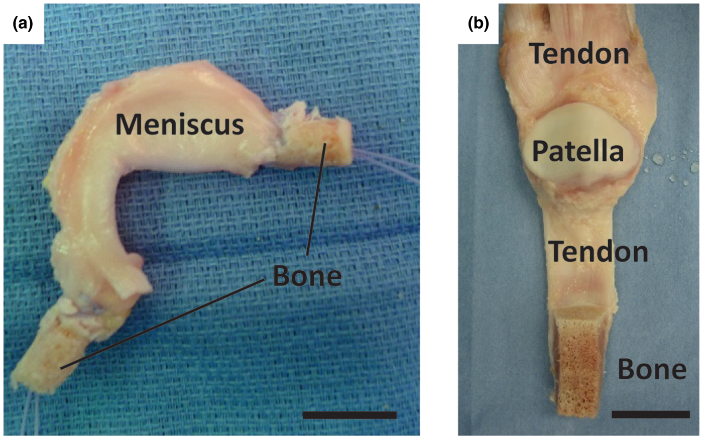
The ligamentous, tendinous, and meniscal attachments, also called entheses, act to anchor soft tissues to bone. Injuries to the enthesis often result in acute disability and may ultimately pre-dispose the affected joint to diseases such as osteoarthritis, a disease estimated to affect over 70% of people aged 55–78.[Reference Brooks4] Severe injuries of these tissues often require replacement, which is typically accomplished using cadaveric tissue (allograft) or tissue removed from the patient's own body (autograft) (Fig. 1). Allograft tissue can effectively replace the damaged tissue in its entirety. For example, in the case of meniscus replacement, an allograft tissue consists of the entire meniscus, including the entheses.[Reference Shelton and Dukes5] Proper fixation of the implant at the entheses is a necessity for surgical success.[Reference Khetia and McKeon6] Including the entheses also obviates the need to reconstruct this complex interface between soft tissue and bone. Despite the advantages of allografts, limitations related to cost, tissue sizing, availability, and potential for an adverse immune response still exist. Autograft tissue is also frequently used for ligament and tendon repair, where a portion of the patient's native tendon is used. However, autograft tissue replacement can require multiple surgical sites, and harvest of autografts from ligament sites is not feasible. Tissue engineered implants combine the advantages of both the allograft and autograft options in that they offer a customizable, living implant that can be produced without requiring a donor or donor site.
Surgical adult human allograft replacements for (a) meniscus and (b) patellar tendon with full bone insertions intact. Sutures are threaded through the insertion points and pulled into bone tunnels to anchor allograft tissues in place. Leaving the entheses intact obviates the need for enthesis healing, increasing the success rate for patient recovery. Scale bars are 20 mm.
Tissue engineering interfaces requires an interdisciplinary effort among biomedical engineers, materials scientists, and orthopedic surgeons. These tissues are complex in nature, consisting of multi-scale arrangements of multiple tissue types. The mechanical function of these interfaces is derived in part from the hierarchical arrangement of relatively simple building blocks into composite materials. Interfacial tissues are integrated into a continuous gradient populated by a variety of cell types, and these cell types are accompanied by chemical factors and signaling molecules that influence the maturation of these tissues and maintain homeostasis.[Reference Yang and Temenoff7–Reference Font Tellado, Rosado Balmayor and Van Griensven9] Two types of entheses can be found in the body: direct and indirect. Direct entheses have a fibrocartilaginous region between the bone and the highly organized collagen fibers of the ligament, tendon, etc.[Reference Hammoudi and Temenoff10] Conversely, indirect entheses are usually observed on the shafts of long bones and have fibers that connect directly into bone (Sharpey's fibers) (Fig. 2). This review will focus on direct entheses.
Schematic of the direct and indirect entheses for the femoral and tibial insertions of the medial collateral ligament (MCL), respectively. Abbreviations are as follows: femur (F), tibia (T), fibrocartilage (FC), ligament (L), bone (B), periosteum (P), meniscus (M), joint capsule (JC), and epiphyseal plate (EP). Reprinted from Springer Anatomy and Embryology, An immunohistochemical study of enthesis development in the medial collateral ligament of the rat knee joint, Volume 194, Issue 4, 1996, 399–406, J. Gao, K. Messner, J. R. Ralphs, M. Benjamin, © Springer-Verlag 1996, with permission of Springer.[Reference Gao, Messner, Ralphs and Benjamin11]
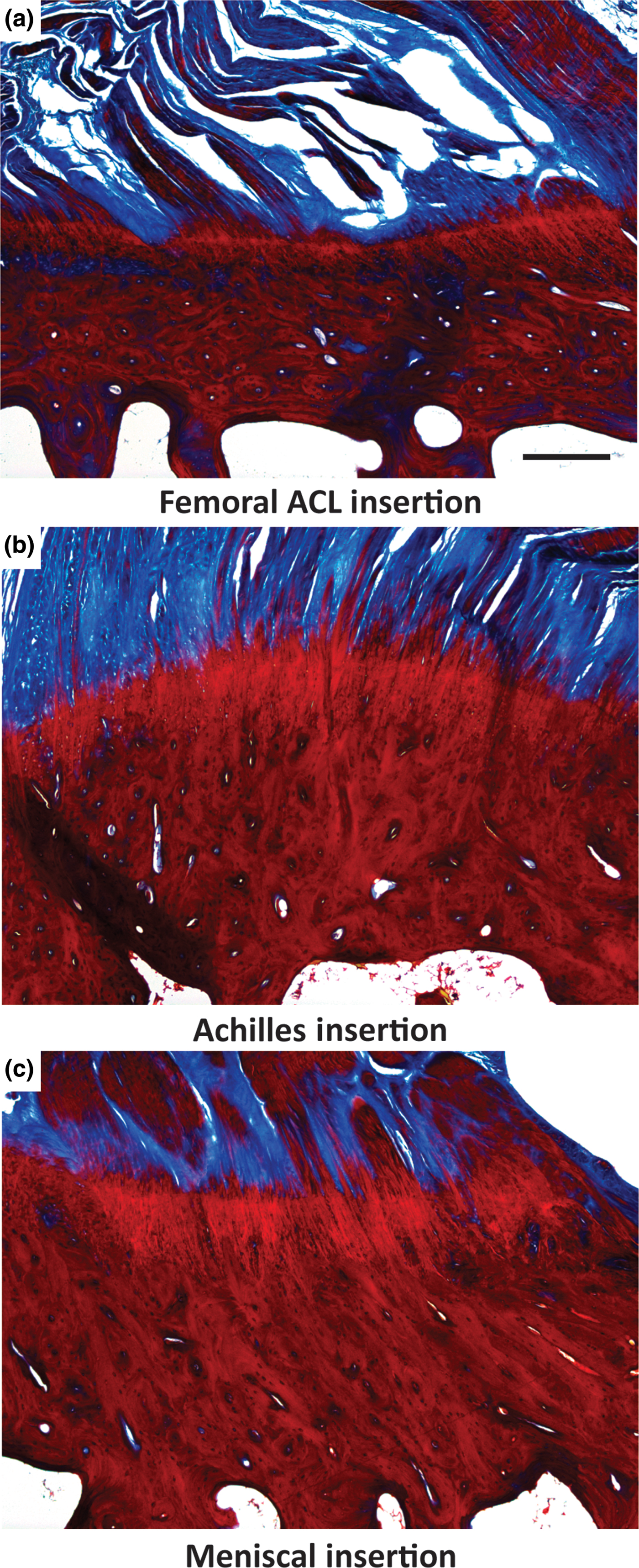
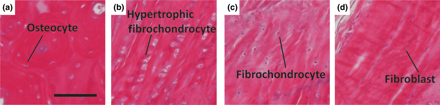
All direct entheses have the same general subdivisions based on tissue type, as observed through histological analysis: subchondral bone, calcified fibrocartilage, uncalcified fibrocartilage, and oriented soft tissue.[Reference Spalazzi, Boskey, Pleshko and Lu12–Reference Messner and Gao14] Comparative structures of tendon, ligament, and meniscal entheses are highlighted using a tetrachrome stain of sagittal sections of these interfaces (Fig. 3). The extracellular matrix (ECM) of these tissues consists primarily of collagen, proteoglycans, and apatite. The interfacial region consists of a spatial distribution of cell types, moving from bone cells (osteoblasts, osteoclasts, osteocytes) to hypertrophic fibrochondrocytes in the calcified fibrocartilage to fibrochondrocytes in the uncalcified fibrocartilage to fibroblasts in the oriented collagenous region of the enthesis (Fig. 4). These cell types are accompanied by biochemical and biomechanical cues that also vary by region, often with temporal and spatial gradients in concentration.[Reference Gao15–Reference Benjamin and Ralphs18] The demarcation between calcified and uncalcified fibrocartilage is called the tidemark, referring to a distinctive transition between tissue regions. However, recent evidence indicates the presence of a mineral gradient at what has been historically referred to as the tidemark, meaning that this shift in composition may be less distinct.[Reference Yang and Temenoff7, Reference Spalazzi, Boskey, Pleshko and Lu12, Reference Genin, Kent, Birman, Wopenka, Pasteris, Marquez and Thomopoulos19]
Light microscope images of three different osteochondral interfacial tissues, stained with tetrachrome stain. All images show ovine tissue, cut in the sagittal plane of the enthesis: (a) the femoral anterior cruciate ligament (ACL) insertion, (b) insertion point of gastrocnemius tendon with the calcaneal bone, referred to here as the Achilles insertion, and (c) the meniscal insertion. Trabecular pores are visible on the bottoms of each image, beneath dense calcified bone (deep red). Porous regions transition through to fibers (blue). Note the varying thicknesses of the interfacial regions, and variable morphology of the intermediate bony regions per anatomy. Scale bar is 400 µm.
Representative histologic images of cellular phenotypes from (a) bone, (b) calcified fibrocartilage, (c) fibrocartilage, and (d) ligament from a mature ovine ACL enthesis (hematoxylin and eosin). (a) Osteocyte embedded between lamellae of an osteon. (b) Enlarged hypertrophic fibrochondrocytes organized in columns indicating rapid proliferation. (c) Fibrochondrocyte in disorganized fiber region. (d) Elongated spindle shaped fibroblast between large organized fibers. Scale bar is 200 µm.
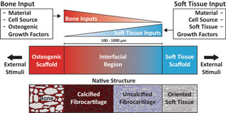
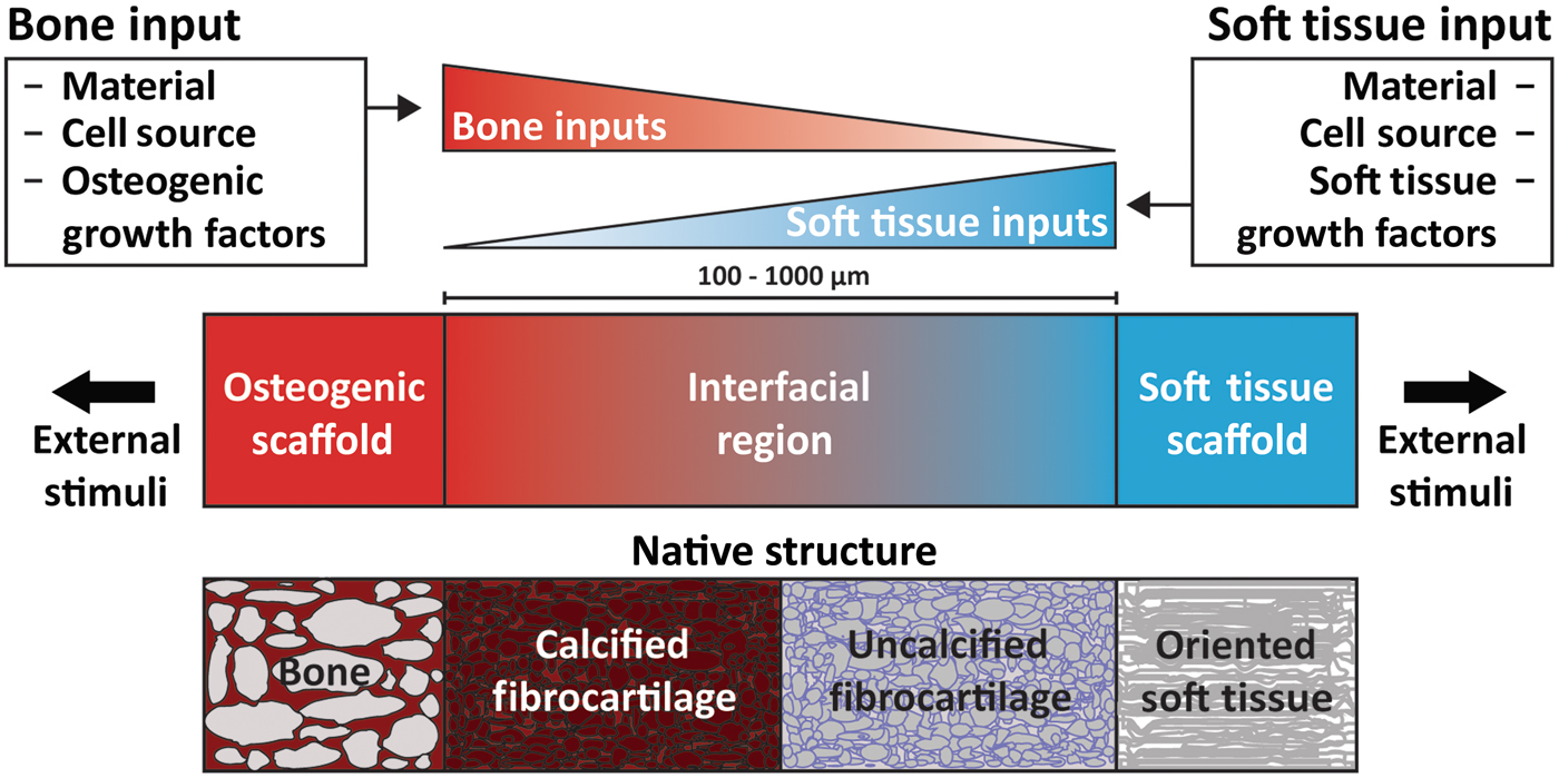
As a prospective review, this paper highlights current methods of designing and fabricating a tissue engineered enthesis construct with a view toward future directions. Enthesis engineering is still at an early stage, even when compared with other tissue engineering efforts. While prior studies have examined methods to engineer bulk tendon, ligament, meniscus, and even other orthopedic interfaces,[Reference Buma, Ramrattan, van Tienen and Veth20, Reference Rodrigues, Reis and Gomes21] such as the osteochondral interface and the periodontal interface,[Reference Di Luca, Van Blitterswijk and Moroni22, Reference Vaquette, Fan, Xiao, Hamlet, Hutmacher and Ivanovski23] few studies have focused on engineering entheseal tissues.[Reference Yang and Temenoff7–Reference Font Tellado, Rosado Balmayor and Van Griensven9] This review divides the orthopedic interface engineering process into three main design inputs: materials processing methods, cellular contributions, and biochemical factors. These inputs must be developed in parallel for both the osteogenic and soft tissue-generating portions of a construct, and then combined across an interfacial region of the construct to promote continuity and integration. This interface can be formulated into either continuous but opposing gradients of soft tissue and bone inputs or a compartmentalized interface, consisting of multiple regions that reflect the composition of the native tissue. Following tissue assembly, the maturation process is the key to promote eventual integration with the local joint tissues (Fig. 5). The following sections discuss these inputs individually and address how these methods can be utilized in parallel to generate soft tissue-to-bone interfaces.
Schematic highlighting the process for constructing a tissue engineered interfacial construct. Materials, cell source, and growth factors are the central input considerations for a tissue engineering study design. The interfacial region requires complementary gradients of bone and soft tissue inputs. Following construct assembly, external stimuli such as mechanical loading can be applied to further aid in tissue development.
Materials processing methods
The architecture of the enthesis is complex, consisting of hierarchical arrangements of collagen fibrils, proteoglycans, and apatite [Ca10(PO4)6(OH)2] crystals. The molecular composition, spatial distribution, and nano- to micro-scale assembly of these components dictate the properties of each tissue region and are critical for defining the mechanical stability of the entire enthesis. The following sections describe the native enthesis structure and methods for mimicking this structure through tissue engineering.
Native organization
Collagen is the main component of the enthesis. Three major types of collagen are found across the interface: type I, type II, and type X. Collagens III, V, and VI are also found in these interfaces at much lower concentrations.[Reference Waggett, Ralphs, Kwan, Woodnutt and Benjamin24] Types I and II collagen are fibrillar collagens, meaning they self-assemble into organized nanofibers, ~50–500 nm in diameter.[Reference Fratzl and Weinkamer25] Type I collagen is deposited in association with tensile forces and is found in bone and ligamentous tissue. Type II collagen is associated with compressive forces and is found primarily in fibrocartilaginous regions.[Reference Gao15, Reference Moffat, Sun, Pena, Chahine, Doty, Ateshian, Hung and Lu26] The presence of compressive forces has been postulated to aid in the reduction of stress concentrators in the enthesis, possibly indicating the origin of type II collagen.[Reference Liu, Thomopoulos, Birman, Li and Genin27] These fibrillar collagens can further assemble into increasingly large fiber-like structures. This type of organization is found within the oriented soft tissue of the entheseal attachments and is typically associated with type I collagen. Collagen fibrils in this region can bundle together into structures called fascicles, ~50–300 µm in diameter, which are in turn bundled into large fibers, ~100–500 µm in diameter.[Reference Fratzl and Weinkamer25] Type X collagen is found in calcified fibrocartilage regions and is non-fibrillar.[Reference Gao15] Type X collagen is thought to play a role in ossification, but its exact function is unknown. Hypotheses include type X collagen acting to regulate mineralization at the ossifying front, and type X collagen functioning as a matrix protein and facilitating the ingrowth and mineralization of new bone.[Reference Shen28]
The enthesis contains proteoglycans that bind water, provide compressive strength, and contribute to collagen fiber formation. Proteoglycans consist of a central core protein and at least one covalently attached glycosaminoglycan (GAG) chain. GAGs are linear, highly charged polysaccharides that can contain sulfate and carboxylate groups.[Reference Hardingham and Fosang29] Aggrecan is the predominant proteoglycan in cartilage and fibrocartilage and is the largest of the proteoglycans. In tendon and ligament, aggrecan is most prevalent in regions of compression and in the fibrocartilage of the insertion site.[Reference Waggett, Ralphs, Kwan, Woodnutt and Benjamin24, Reference Benjamin and Ralphs30] Similar to ligament and tendon, aggrecan in the meniscus is located in the inner portion of the meniscus, which is subject to more compressive loads, and the entheseal attachments.[Reference Melrose, Smith, Cake, Read and Whitelock31, Reference Rossetti, Kuntz, Kunold, Schock, Grabmayr, Sieber, Burgkart and Bausch32] The large “bottle brush” structure and negative charge of aggrecan helps to bind and retain water, which contributes to the ability of the tissue to resist compression.[Reference Tavakoli Nia, Han, Soltani Bozchalooi, Roughley, Youcef-Toumi, Grodzinsky and Ortiz33] Small leucine-rich proteoglycans (SLRPs) such as fibromodulin, decorin, and biglycan are known to bind to collagen and help to regulate collagen fiber formation and maintenance.[Reference Garg, Berg, Silver and Garg34–Reference Vogel, Paulsson and Heinegård36] SLRPs are prevalent in association with highly organized collagen bundles of tendon, ligament, and meniscus.[Reference Rossetti, Kuntz, Kunold, Schock, Grabmayr, Sieber, Burgkart and Bausch32, Reference Vanderploeg, Wilson, Imler, Ling and Levenston37] Aggrecan is often found in regions of soft tissue-to-bone interfaces under compressive loading, while SLRPs are found in regions with large fibers experiencing tensile loads.[Reference Rossetti, Kuntz, Kunold, Schock, Grabmayr, Sieber, Burgkart and Bausch32]
Apatitic mineral is found within the subchondral bone and calcified fibrocartilage regions of the interfacial tissues. The mineral phase is primarily non-stoichiometric hydroxyapatite with carbonate substitutions, as opposed to geologic hydroxyapatite,[Reference Wopenka and Pasteris38] that is arranged into nanocrystalline platelets. In bone, these platelets are contained within collagen fibrils and are oriented with their c-axis parallel to the direction of the fibril. Non-collagenous proteins are thought to organize the apatite platelets into the intrafibrillar spacing of collagen, but the exact mechanism through which this hierarchical structuring occurs is unknown.[Reference Nudelman, Lausch, Sommerdijk and Sone39] Thorough reviews of bone structure are available.[Reference Weiner and Wagner40, Reference Reznikov, Shahar and Weiner41] The mineral phase in calcified fibrocartilage is also mainly carbonate-substituted hydroxyapatite, but the organization of the crystals within the matrix is not as well understood.[Reference Spalazzi, Boskey, Pleshko and Lu12, Reference Schwartz, Pasteris, Genin, Daulton and Thomopoulos42]
Aggregating the above information, subchondral bone consists of type I collagen fibrils infiltrated with nanocrystalline, carbonated apatite arranged circumferentially around pores, typically of the order of 1 mm in diameter.[Reference Keaveny, Morgan, Niebur and Yeh43] This structure transitions into non-porous calcified fibrocartilage, consisting of type II and type X collagen, apatitic mineral, and proteoglycans. Uncalcified fibrocartilage consists of splayed fibrils of type II collagen with proteoglycans. These splayed fibrils transition from the uncalcified fibrocartilage region into large type I collagen fibers that make up the oriented fiber region of the enthesis.[Reference Rossetti, Kuntz, Kunold, Schock, Grabmayr, Sieber, Burgkart and Bausch32, Reference Deymier-Black, Pasteris, Genin and Thomopoulos44] Understanding native structure/composition should inform material selection for tissue engineering.
Materials selection
Appropriate materials for a tissue engineered scaffold must possess adequate mechanical properties, support cellular attachment and differentiation/proliferation, and potentiate cellular remodeling. Since the modulus ranges drastically across soft tissue-to-bone interfaces, a variety of materials have been used for tissue engineered constructs. To match the moduli of the stiff, mineralized regions of the enthesis, various calcium phosphate minerals, such as hydroxyapatite and tricalcium phosphate, and bioglass have been used.[Reference Allan, Pilliar, Wang, Grynpas and Kandel45–Reference Spalazzi, Doty, Moffat, Levine and Lu51] The compliant portions of the enthesis have been constructed from polymers and copolymers consisting of poly(capralactone) (PCL), poly(lactic acid) (PLA), poly(glycolic acid) (PGA), and/or poly(ethylene glycol) diacrylate,[Reference Nyberg, Rindone, Dorafshar and Grayson49, Reference Spalazzi, Doty, Moffat, Levine and Lu51–Reference Paxton, Donnelly, Keatch and Baar56] as well as other biopolymers such as silk, agarose, gelatin, hyaluronic acid, and collagen.[Reference Kim, Kim, Choi, Jeong, Jo and Cho48, Reference Altman, Horan, Lu, Moreau, Martin, Richmond and Kaplan57–Reference Wang, Shan, Choi, Oh, Kepler, Chen and Lu62] Decellularized or demineralized native matrices have also been used to engineer the enthesis.[Reference Nyberg, Rindone, Dorafshar and Grayson49, Reference McCorry, Mansfield, Sha, Coppola, Lee and Bonassar60, Reference Chang, Lin, Lin, Chou and Liu61, Reference Xu, Kuntz, Foehr, Kuempel, Wagner, Tuebel, Deimling and Burgkart63, Reference Sundar, Pendegrass and Blunn64]
Materials-based design and fabrication
The complex structure of the enthesis is related to its function, providing continuity and integration between multiple tissues with differing properties. The necessity for this integration and continuity arises from the loading of such interfaces in tension;[Reference Lu and Thomopoulos8] hence, failure modes like delamination become relevant for poorly integrated constructs. To promote continuity, various materials processing techniques have been used. Many of these techniques revolve around the construction of gradients or the binding of multiple “compartmentalized” materials. Controlled crystal growth on electrospun poly(lactic-co-glycolic) acid (PLGA) resulted in a nanofiber scaffold with a mineral gradient.[Reference Liu, Lipner, Xie, Manning, Thomopoulos and Xia47] This gradient was formed through syringe pump-mediated injection of a calcium and phosphate salt-containing solution. Upon cell seeding, the activity of alkaline phosphatase (ALP), an enzyme associated with mineral deposition, the expression of RUNX2, an osteoblast-related transcription factor, and the expression of osteocalcin, an osteoblast-related protein, were correlated with mineral deposition. Cellular density and cell proliferation were negatively correlated with mineral deposition.[Reference Liu, Lipner, Xie, Manning, Thomopoulos and Xia47] These results indicate that proper processing and appropriate arrangement of enthesis-related materials result in spatially localized cellular responses that mimic those found in the body. However, implantation of this scaffold for the repair of the murine supraspinatus tendon resulted in scar formation, indicating that further processing is required for optimal enthesis reconstruction.[Reference Lipner, Shen, Cavinatto, Liu, Havlioglu, Xia, Galatz and Thomopoulos65]
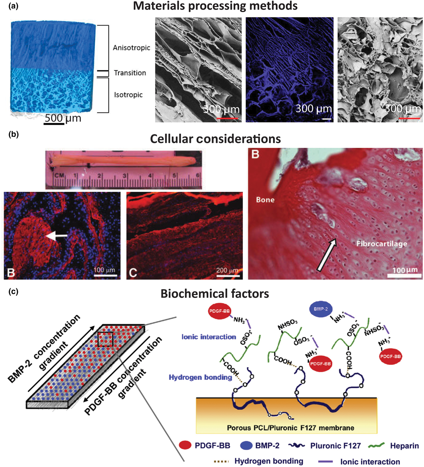
Regional integration in scaffolds can also be induced through the production of microstructure gradients. For example, freeze-casting coupled with salt-leaching enabled the formation of a multi-region scaffold composed of silk fibroin [Fig. 6(a)].[Reference Font Tellado, Bonani, Rosado Balmayor, Föhr, Motta, Migliaresi and van Griensven58] The processing conditions were designed to form a continuous scaffold with a porous, trabecular bone-like structure that transitions into a fiber-like morphology. The porous region results from salt leaching, in which a solution of silk fibroin and NaCl is frozen and freeze-dried. The precipitated salt crystals are subsequently dissolved, creating pores within the silk matrix. This region transitions to a fiber-like morphology, created using freeze casting, a process in which directional freezing is used to grow elongated ice crystals within a polymer solution. During solidification, the polymer, i.e., silk fibroin, is concentrated into the boundaries between the crystals.[Reference Wegst, Bai, Saiz, Tomsia and Ritchie66] Upon sublimation of the ice crystals, oriented fiber-like structures composed of silk fibroin remain. These processing methods result in a continuous silk structure that mimics the morphology of collagen in the native enthesis.[Reference Font Tellado, Bonani, Rosado Balmayor, Föhr, Motta, Migliaresi and van Griensven58] Similar scaffolds have been produced for the osteochondral interface, demonstrating the customizability of these techniques.[Reference Ding, Zhu, Xu, Zhang, Zhao, Ji, Wang, Wang, Li, Kong, Ma and Yang67]
Examples of tissue engineered interface constructs for soft tissue to bone. (a) Biphasic anisotropic silk fibroin scaffold with integrated fiber/bone interface. Images from left-to-right: μCT of full construct, field emission scanning electron microscopy (FESEM) image of, anisotropic (fiber) region, fluorescence microscopy image of transition region, and FESEM image of porous (trabecular) region. Reprinted with permission from TISSUE ENGINEERING, Part A, Volume 23, Issue 15–16, published by Mary Ann Liebert, Inc., New Rochelle, NY[Reference Font Tellado, Bonani, Rosado Balmayor, Föhr, Motta, Migliaresi and van Griensven58] (b) Bone–ligament–bone ACL replacement generated using stem cell self-assembly and targeted differentiation. Images from left-to-right: full tissue engineered construct, immunostained for collagen (red) and DAPI-stained (nuclear stain) section showing bony region prior to implantation, immunostained for collagen (red) and DAPI-stained (nuclear stain) section showing ligament region prior to implantation, image of regenerated fibrocartilaginous region with aligned nuclei (arrow) after 2 months implantation. Reprinted with permission from TISSUE ENGINEERING, Part A, Volume 18, Issue 1–2, published by Mary Ann Liebert, Inc., New Rochelle, NY.[Reference Ma, Smietana, Kostrominova, Wojtys, Larkin and Arruda68] (c) Porous membrane with inverse gradients of PDGF and BMP-2 for tendon-bone repair. Reprinted from Acta Biomaterialia, Volume 10, Issue 3, Hyun Ki Min, Se Heang Oh, Jonh Min Lee, Gun Il Im, Jin Ho Lee, Porous membrane with reverse gradients of PDGF-BB and BMP-2 for tendon-to-bone repair: In vitro evaluation on adipose-derived stem cell differentiation, 1272–1279, Copyright © 2013, with permission from Elsevier[Reference Min, Oh, Lee, Im and Lee69]
Structural characteristics are important in that they not only affect the mechanical properties of the scaffold but also drive cellular differentiation. Fiber alignment drives matrix deposition rates in meniscal fibrochondrocytes and mesenchymal stem cells (MSCs) (the progenitor cells for bone, cartilage, etc.).[Reference Baker and Mauck70] Pore size affects the production of cartilage matrix proteins by cells. For example, smaller pore sizes cause cells to produce more GAGs.[Reference Di Luca, Van Blitterswijk and Moroni22] In addition to structurally derived cellular effects, the material composition of scaffolds also has an effect on differentiation. The addition of hydroxyapatite to scaffolds improves osteogenic properties and increases cellular attachment,[Reference Allan, Pilliar, Wang, Grynpas and Kandel45, Reference Paxton, Donnelly, Keatch and Baar56] and the presence of GAGs in scaffolds drives cells toward a chondrogenic lineage.[Reference Park, Yang, Woo, Yang, Na and Park71, Reference Han, Heo, Driscoll, Delucca, McLeod, Smith, Duncan, Mauck and Elliott72]
The use of materials to control cellular responses can also be achieved through biodegradability and remodeling. For example, a compartmentalized triphasic scaffold, created by sintering polyglactin mesh, PLGA microspheres, and bioglass and PLGA microspheres together, shows varying rates and types of tissue ingrowth into the scaffold following subcutaneous implantation.[Reference Spalazzi, Doty, Moffat, Levine and Lu51] All regions of the scaffold showed collagen deposition, and the bioglass and PLGA microsphere region allowed for mineral deposition. The polyglactin region degraded entirely, producing a fibrocartilage-like area between the polyglactin and PLGA microsphere region.[Reference Spalazzi, Doty, Moffat, Levine and Lu51, Reference Spalazzi, Dagher, Doty, Guo, Rodeo and Lu73] In design of scaffolds that utilize multiple materials, structural considerations must be made for the types of mechanical forces to which the scaffold will be subjected. For example, fused microspheres are resistant to compression and polyglactin mesh is resistant to tension, but neither structure is designed to resist shear. Additionally, the differing structures could result in stress concentrations at the interface between the materials, arising from dissimilarities in their Poisson's ratios. Use of biodegradable materials can promote tissue infiltration, and particularly in this case, can be used to diminish the sharpness of the interface over time. The mechanism of biodegradation should also be considered for tissue engineering. Biodegradable polymers like PLA and PGA can be degraded through hydrolysis, opening up space for tissue to grow into, whereas biopolymers such as collagen must be enzymatically degraded and rearranged by cells, providing a template for remodeling. For example, cells rearranged collagen gels into large, oriented fibers during culture of a meniscus construct, indicating the value of incorporating cellular remodeling capability into a scaffold.[Reference Puetzer, Koo and Bonassar74] Implementation of continuity, integration of structure, and support for cellular remodeling in scaffolds allow for control of mechanical properties, strengthening of interfacial regions, and ability of the scaffold to integrate with native tissue upon in vivo implantation.
Cellular contributions
Cells and cellular interactions drive the maturation of scaffolds before implantation and integration of scaffolds with native tissue after implantation; therefore, cellular content is an essential component to the design of any tissue engineered construct. Biocompatibility, cellular integration, and cellular remodeling are key considerations when creating, culturing, and implanting a construct. Cells function in complex three-dimensional (3D) environments and respond to a plethora of inputs including materials interactions, substrate stiffness, mechanical conditioning, biochemical signaling, and cell–cell interactions. Tissue engineering approaches utilize such inputs to drive maturation of a functional construct.
Native cell types
Soft tissue-to-bone interfaces span four regions with distinct cellular phenotypes (Figs. 3 and 4). Each cellular type found in the enthesis has a distinctive behavior, cell shape, matrix production profile, and genetic expression that define its phenotype. Osteoblasts, osteoclasts, and osteocytes are the three main cell types that reside in bone. Osteoblasts initiate new bone formation, while osteoclasts resorb and remodel bone. An osteocyte is a terminally differentiated osteoblast that resides in the mineralized matrix to maintain bone homeostasis [Fig. 4(a)]. Together, these cells regulate bone formation and maintenance. The bone phenotype is typically quantified by expression or accumulation of proteins, such as osteopontin and osteocalcin, type I collagen, markers of mineralization, such as ALP activity, and expression of transcription factors, such as RUNX2.[Reference Lian and Stein75] The transition from bone to the calcified fibrocartilage region is regulated by hypertrophic fibrochondrocytes [Fig. 4(b)]. Hypertrophy is the process in which chondrocytes increase in size and secrete type X collagen in a mineralized cartilaginous matrix.[Reference Mackie, Ahmed, Tatarczuch, Chen and Mirams76] In contrast, chondrocytes are found in cartilage and exhibit a rounded morphology. These cells reside in a proteoglycan-rich (mostly aggrecan) matrix composed of collagens I and II. Chondrocytes, found in the cartilaginous tissue, have upregulated levels of aggrecan, type II collagen, link protein, Sox9, and COMP genes.[Reference Sandell and Aigner77] Fibrochondrocytes that reside in the uncalcified fibrocartilage region of the enthesis are named as such because they exhibit phenotypic markers of both fibroblasts and chondrocytes [Fig. 4(c)].[Reference Sanchez-Adams and Athanasiou78] The native cell phenotypes serve as benchmarks for cell behavior and stem cell differentiation in tissue engineered constructs. Ligament cells and tenocytes (tendon cells) are often described as exhibiting a fibroblastic phenotype due to their spindle shape and production of type I collagen [Fig. 4(d)].[Reference Benjamin and Ralphs18] While these two cell types belong to distinctly different tissues, they share many common markers. Key positive markers for this phenotype are production of type I collagen, tenascin-C, scleraxis, tenomodulin, and proteoglycans such as decorin, biglycan, versican, lumican, and fibromodulin.[Reference Spanoudes, Gaspar, Pandit and Zeugolis79, Reference Hasegawa, Nakahara, Kinoshita, Asahara, Koziol and Lotz80]
Tissue engineering with cells
A consistent challenge of producing these soft tissue-to-bone interfaces is incorporating cells into the materials processing methods of the scaffold. Cellularizing these constructs can be accomplished by either encapsulating cells directly into the scaffold or by seeding cells onto the material surface and directing migrating cells into the scaffold. Growth factors or other chemoattractants are useful to encourage cellular migration and infiltration into scaffolds.[Reference Sundar, Pendegrass and Blunn64, Reference Lee, Rodeo, Fortier, Lu, Erisken and Mao81, Reference Monibi and Cook82] Processing cells and materials together restricts the conditions in which a scaffold can be processed. Cells require a specific operational window of temperature, pH, pressure, strain, osmolarity, and ion and solute balance in order to maintain viability. Furthermore, the soft tissue-to-bone interface contains an array of cell types. The number of cell types and the cellular locations in the tissue engineered scaffold play a role in soft tissue-to-bone interface assembly, culture, and development.
Given the gradient of cell types present in the enthesis, co-culture is one method to generate a graded interface. Different cell types are constantly interacting during native development and have intertwined signaling feedback mechanisms that are critical to development.[Reference Benjamin and Ralphs18, Reference Mackie, Ahmed, Tatarczuch, Chen and Mirams76, Reference Zelzer, Blitz, Killian and Thomopoulos83] Ex vivo co-culture mediates cell–cell contact and paracrine interactions that have been shown to influence cellular phenotype. Co-culturing of chondrocytes and osteoblasts in direct contact using a high cell density 3D micromass reduced GAG deposition in chondrocytes and cell-mediated mineralization in osteoblasts.[Reference Jiang, Nicoll and Lu84] Furthermore, co-culture can be used as a tactic to guide stem cell differentiation.[Reference McCorry, Puetzer and Bonassar85–Reference Hoben, Willard and Athanasiou89] One strategy to create an integrated gradient is to co-culture the desired cell types and generate cell gradients that utilize cell–cell interactions to mature the material into a graded interface. For ligament–bone interfaces, 2D co-culture of fibroblasts and osteoblasts, modeled using a fibroblast region, interface region, and osteoblast region, decreased cell proliferation and increased cell-mediated mineralization by fibroblasts. In addition, production of type II collagen and aggrecan increased, indicating that co-culture interactions can lead to cell trans-differentiation from one cell phenotype to another.[Reference Wang, Shan, Choi, Oh, Kepler, Chen and Lu62] Co-culturing of different cell types is a useful technique to integrate the different tissue regions of the soft tissue-to-bone interface.
An alternative to using multiple cell types is using MSCs, which can differentiate into multiple cell types. In vivo entheses begin as dense mesenchymal condensates and develop into complex interfaces.[Reference Gardner and O'Rahilly90–Reference Mérida-Velasco, Sánchez-Montesinos, Espín-Ferra, Rodríguez-Vázquez, Mérida-Velasco and Jiménez-Collado92] Since MSCs have the capacity to differentiate into all the cell phenotypes of the enthesis, MSCs are a logical cell source to use for tissue engineering the enthesis.[Reference Caplan and Dennis93, Reference Mackay, Beck, Murphy, Barry, Chichester and Pittenger94] MSCs from bone marrow (bmMSCs) are a popular source for tissue engineering, because they are easily obtained and expanded. Adipose-derived stem cells (ASCs) are another common stem cell source. Since ASCs are easily obtained from fat which is considered surgical debris, they are the most readily available stem cell source from human tissue. While ASCs do have multi-potent properties, they have been shown to be less effective than bmMSCs at differentiating into cartilage and bone.[Reference Im, Shin and Lee95] Stem cells seeded into tissue engineered enthesis constructs rely on mimicking the biomaterial and biochemical inputs that direct differentiation during development. For example, regional changes in pore alignment of a tendon/ligament enthesis silk fibroin scaffold resulted in corresponding ASC differentiation into cartilage and tendon lineages [Fig. 6(a)].[Reference Font Tellado, Bonani, Rosado Balmayor, Föhr, Motta, Migliaresi and van Griensven58] These examples emphasize the importance of scaffold material and biochemical design in order to inform cell behavior when generating enthesis constructs.
Construct geometry and chemistry have been shown in multiple systems to affect cellular phenotype through cell–material interactions.[Reference Spalazzi and Lu96, Reference Gunja and Athanasiou97] Cellular phenotypes can be dictated by cell–material interactions. A material such as collagen has cellular adhesion sites, allowing cells to bind and spread, encouraging the cells to develop a fibroblastic morphology. Alternatively, a material lacking in cell adhesion sites, like alginate, prevents cells from binding, encouraging a chondrogenic morphology.[Reference Zeltz and Gullberg98, Reference Augst, Kong and Mooney99] Cell morphology, such as a fibroblastic or chondrogenic morphology, has been shown to be an indicator for cell behavior and matrix production.[Reference Baker, Nathan, Gee and Mauck100] Scaffold mechanical properties are known to direct stem cell fate, where materials with stiffer structures promote osteogenic differentiation.[Reference Tse and Engler101, Reference Engler, Sen, Sweeney and Discher102] Lastly, chemical composition dictates cellular response. Cells embedded in a proteoglycan-rich region experience increased strain shielding compared to cells embedded in collagen fibers when a tissue-level mechanical deformation is applied to the scaffold.[Reference Han, Heo, Driscoll, Delucca, McLeod, Smith, Duncan, Mauck and Elliott72] Furthermore, the arrangement and alignment of fibers in a 3D microenvironment affects cellular behavior and the distribution of applied loads. In an aligned poly(ethylene oxide) scaffold, cells attach and elongate in the direction of the fibers. Fiber alignment aided bmMSC differentiation into a fibrous phenotype compared with the same bmMSCs in pellet culture which developed a chondrogenic phenotype.[Reference Baker, Nathan, Gee and Mauck100] Furthermore, aligned fibers improved ligamentous phenotype, as cells develop characteristic spindle shapes and increase production of collagen when compared with random fiber alignment. The alignment of fibers also affects the cellular response to an applied strain, with longitudinal strains in the fiber direction inducing the largest increase in collagen production.[Reference Lee, Shin, Cho, Kang, Kim, Park and Shin103, Reference Subramony, Dargis, Castillo, Azeloglu, Tracey, Su and Lu104] These studies emphasize the importance of material mechanical properties and structure when considering cellular interactions and response.
Another approach to tissue engineering soft tissue-to-bone interfaces shifts the focus from materials design to utilizing the cells themselves to create the scaffold. Cells grown in monolayers have the ability to proliferate to fill the surface area and then self-assemble to form their own matrix. A multi-component bone–ligament–bone tissue engineered anterior cruciate ligament (ACL) graft was created using confluent cell monolayers [Fig. 6(b)]. The bmMSCs were first pre-differentiated into ligamentous or bone pathways in monolayer and then assembled together into a 3D scaffold. The resulting scaffold showed sufficient properties for ACL replacement and performed well during long-term implantation in an ovine model.[Reference Ma, Smietana, Kostrominova, Wojtys, Larkin and Arruda68] Gene transfer is another strategy to spatially regulate genetic modification and differentiation of primary dermal fibroblasts. A retrovirus encoding the factors RUNX2 and cbfa1 was used to induce osteoblastic and fibroblastic differentiation, respectively.[Reference Phillips, Burns, Le Doux, Guldberg and García105] These techniques demonstrate that cells can be used to produce complex gradients for soft tissue-to-bone interfaces.
Biochemical factors
A range of biochemical factors can influence production and remodeling of ECM by cells. Growth factors are proteins that are secreted by cells and act as signaling molecules to other cells via cell surface receptors. These molecules play active roles in establishing the complex structure of the enthesis, healing the tissue after injury, and maintaining tissue homeostasis. This section highlights relevant biochemical signals in development and their application to enthesis tissue engineering.
Native biochemical signaling
Soft tissue-to-bone interfaces have a wide array of growth factors that influence cellular activities such as differentiation, proliferation, apoptosis, and matrix production. Key growth factor contributors to bone growth, repair, and differentiation are bone morphogenic proteins (BMPs), transforming growth factor-βs (TGF-βs), and insulin-like growth factors (IGFs) (Table I).[Reference Urist, DeLange and Finerman106–Reference Lieberman, Daluiski and Einhorn108] The growth plate contains similar regional zones to the enthesis since it is an interface between bone and cartilage. Growth factors secreted in the growth plate are essential to endochondral bone formation and include IGFs, Indian hedgehog (Ihh), parathyroid hormone-related peptide (PTHrP), BMPs, Wnts, fibroblast growth factors (FGFs), and TGF-βs.[Reference Mackie, Ahmed, Tatarczuch, Chen and Mirams76] Key players in bulk tendon and ligament development, healing, and remodeling are IGFs, growth and differentiation factors (GDFs), TGF-βs, vascular endothelial growth factor (VEGF), platelet-derived growth factor (PDGF), and FGFs.[Reference Molloy, Wang and Murrell109, Reference James, Kesturu, Balian and Chhabra110] IGFs, FGFs, TGF-βs, and PDGF are the central growth factors that contribute to developing and maintaining organized collagen structures and high levels of proteoglycans in cartilage and meniscus.[Reference Van der Kraan, Buma, Van Kuppevelt and Van Den Berg111] While many of these growth factors are present in all of these tissues (Table I), the spatial and temporal expression of growth factors are important drivers of tissue development.
Growth factors commonly used in orthopedic tissue engineering applications. See the following reviews for more on specific growth factors.[Reference Lieberman, Daluiski and Einhorn108–Reference James, Kesturu, Balian and Chhabra110, Reference Baylink, Finkelman and Mohan112]
? indicates that no native study on these growth factors has been performed; however, TE applications have been performed using these growth factors and they are believed to play a role.
TGF-βs, GDFs, BMPs, and IGFs regulate bone and joint development by influencing stem cell differentiation, matrix synthesis and remodeling, and cellular migration and proliferation. The TGF-β superfamily is a group of structurally related proteins including TGF-βs, GDFs, and BMPs that influence a broad range of activities in musculoskeletal development. Members of the BMP family encourage stem cell proliferation and differentiation into osteoblasts.[Reference Yoon, Pogue, Ovchinnikov, Yoshii, Mishina, Behringer and Lyons134, Reference Minina, Kreschel, Naski, Ornitz and Vortkamp135] Furthermore, BMPs are osteoinductive, encouraging bone formation and maintenance by recruiting bone-forming cells that result in the formation of mineralized bone. BMPs have successfully navigated the FDA approval process for bone healing applications, notably BMP-2 (Infuse® Medtronic) and BMP-7 (also called OP-1 by Stryker).[Reference Bessa, Casal and Reis136] GDFs, specifically GDF-5, interact closely with BMPs and act as signaling molecules in the growth and differentiation of cartilage, tendon, and ligament.[Reference Farng, Bs, Bs, Bs and Mcallister128, Reference James, Kumbar, Laurencin, Balian and Chhabra129, Reference Wolfman, Hattersley, Cox, Celeste, Nelson, Yamaji, Dube, Diblasio-smith, Nove, Song, Wozney, Rosen, Wolfman, Hattersley, Cox and Anthony137–Reference Decker, Um, Dyment, Cottingham, Usami, Enomoto-Iwamoto, Kronenberg, Maye, Rowe, Koyama and Pacifici139] TGF-βs are prevalent in all of these tissues and are known to play a role in proliferation and stem cell differentiation.[Reference Heine, Munoz, Flanders, Ellingsworth, Lam, Thompson, Roberts and Sporn140] In particular, TGF-β is heavily implicated for its role in chondrogenic differentiation and development.[Reference Leonard, Fuld, Frenz, Downie, Massague and Newman141, Reference Kulyk, Rodgers, Greer and Kosher142] IGF is a regulator of longitudinal bone growth in that it stimulates osteoblast proliferation and differentiation as well as increasing general cell proliferation and ECM synthesis.[Reference Isaksson, Jansson and Gause143–Reference Abrahamsson146] These growth factors are essential signaling contributors to stem cell differentiation and tissue development in native orthopedic tissues.
Several growth factors prevalent in the inflammatory and healing processes also aid in the production of tissue. Vascularization-related growth factors are important in soft tissue development and healing; common growth factors include PDGF and VEGF.[Reference Dormer, Singh, Zhao, Mohan, Berkland and Detamore54, Reference Lieberman, Daluiski and Einhorn108, Reference James, Kesturu, Balian and Chhabra110, Reference Thomopoulos, Harwood, Silva, Amiel and Gelberman132, Reference Midy and Plouët147–Reference Keck, Hauser, Krivi, Sanzo, Warren, Feder and Connolly149] Basic fibroblastic growth factor (FGF-2) is known to contribute to cell proliferation and is expressed in the developmental and healing phases of these tissues.[Reference Thomopoulos, Harwood, Silva, Amiel and Gelberman132, Reference Minina, Kreschel, Naski, Ornitz and Vortkamp135] Growth factors have been specifically targeted for tissue engineering applications, because they are exogenously secreted factors that can be dosed into a system with relative ease and can drive stem cell differentiation and tissue maintenance.
Biochemical applications in tissue engineering
Since growth factors are known to play influential roles in cell behavior, they have been frequently applied to tissue engineer bone, cartilage, meniscus, tendon, and ligament (Table I). BMPs are popular for tissue engineering applications in bone interfaces and have been shown to induce mineralization as well as to stimulate osteoblast proliferation in scaffolds.[Reference Patel, Young, Tabata, Jansen, Wong and Mikos115, Reference Augst, Marolt, Freed, Vepari, Meinel, Farley, Fajardo, Patel, Gray, Kaplan and Vunjak-Novakovic124, Reference Bessa, Casal and Reis136] Scaffolds doped with IGF-I increased cartilage regeneration in growth plate injuries in vivo and increased the collagen and GAG content in tissue engineered cartilage constructs in vitro.[Reference Aguilar, Trippel, Shi and Bonassar130, Reference Sundararaj, Cieply, Gupta, Milbrandt and Puleo150, Reference Gooch, Blunk, Courter, Sieminski, Bursac, Vunjak-Novakovic and Freed151] VEGF was incorporated into a mineralized degradable polymer scaffold to provide osteoconductive signals for bone growth and angiogenesis.[Reference Murphy, Peters, Kohn and Mooney152] GDFs increased type I collagen production in 3D tissue engineered scaffolds.[Reference Farng, Bs, Bs, Bs and Mcallister128, Reference James, Kumbar, Laurencin, Balian and Chhabra129] TGF-βs increase GAG and collagen production which improves the quality of tissue engineered cartilage and meniscus.[Reference Lee, Rodeo, Fortier, Lu, Erisken and Mao81, Reference Macbarb, Makris, Hu and Athanasiou121, Reference Park, Temenoff, Holland, Tabata and Mikos125, Reference Steinert, Palmer, Capito, Hofstaetter, Pilapil, Ghivizzani, Spector and Evans153] Growth factors provide signaling mechanisms to encourage cellular components to exhibit a specific phenotype.
Prominent growth factors in these developmental processes can also guide stem cell differentiation in tissue engineered constructs. BMP-2 combined with hydroxyapatite in a silk fibroin fiber scaffold supported MSC growth and differentiation toward an osteogenic phenotype, quantified by increased BMP-2 transcription levels and mineral deposition.[Reference Li, Vepari, Jin, Kim and Kaplan113] Delivering BMP-2 and BMP-7 sequentially increased ALP activity while suppressing proliferation of MSCs,[Reference Yilgor, Tuzlakoglu, Reis, Hasirci and Hasirci118] highlighting the potential for benefits from temporal application of biochemical factors to cells. Growth factor delivery using a scaffold can increase efficiency of stem cell differentiation into a desired cell phenotype. Localized delivery of IGF in a PLGA scaffold increased MSC chondrogenesis in vitro,[Reference Sundararaj, Cieply, Gupta, Milbrandt and Puleo150] while FGF-2 and TGF-β1 increased chondrogenesis of periosteum derived cells.[Reference Marini, Martin, Stevens, Langer and Shastri122] GDF-5 supplemented medium as well as GDF-5 induction by adenovirus increased expression of type I collagen and scleraxis, associated with tenogensis, in stem cells seeded on a 3D scaffold.[Reference Farng, Bs, Bs, Bs and Mcallister128, Reference Abraham and Haut Donahue1Reference Hardingham and Fosang29] TGF-β3 conjugated with chondroitin sulfate increased MSC chondrogenic differentiation by increasing GAG production and expression of Sox9, COMP, aggrecan, and type II collagen genes.[Reference Park, Yang, Woo, Yang, Na and Park71] Controlled release of TGF-β3 also promoted chondrogenesis of human infrapatellar fat pad-derived stem cells, measured by increased production of sulfated GAGs and collagen.[Reference Kim, Erickson, Choudhury, Pleshko and Mauck127, Reference Almeida, Liu, Cunniffe, Mulhall, Matsiko, Buckley, O'Brien and Kelly154]
Growth factors are useful chemical tools for generating complex materials gradients. Since growth factors can be incorporated into a biomaterial, they can be strategically placed or applied to influence cellular behavior in controlled chemical gradients for soft tissue-to-bone tissue engineering. BMP-2, delivered using microspheres in a poly(propylene fumarate) scaffold, increased bone regeneration and ACL graft fixation.[Reference Parry, Olthof, Shogren, Dadsetan, Van Wijnen, Yaszemski and Kakar116] An integrated gradient of BMP-2 and TGF-β1 has been shown to create a continuous material and phenotypic transition between cartilage and bone.[Reference Tevlek, Hosseinian, Ogutcu, Turk and Aydin50, Reference Dormer, Singh, Zhao, Mohan, Berkland and Detamore54] Application of growth factors is especially favorable when using a single progenitor cell type in the scaffold. Rather than seeding multiple cell types, growth factors can be incorporated to initiate the differentiation of stem cells. ASCs, seeded in a porous PCL/Pluronic F127 membrane with gradients of PDGF, specifically PDGF-BB (tendon) and BMP-2, created a continuous interface between tendon and bone, with PDGF promoting tenogenesis and BMP-2 promoting osteogenesis [Fig. 6(c)].[Reference Min, Oh, Lee, Im and Lee69] In combination with materials processing methods and cells, growth factor gradients contribute to the development of integrated and graded regions for engineered soft tissue-to-bone interfaces.
In addition to facilitating cell–biochemical interactions, growth factors can be sequestered by ECM proteins. Proteoglycans function as physiologic regulators by sequestering growth factors and controlling release. SLRPs, such as biglycan, decorin, and fibromodulin, are capable of binding to TGF-β and are likely to regulate the availability of TGF-β to cells.[Reference Hildebrand, Romarís, Rasmussen, Heinegård, Twardzik, Border and Ruoslahti155] While the exact mechanism is not well understood, increased levels of type II collagen in a scaffold enhance the effect of TGF-β on chondrocytes.[Reference Qi and Scully156] FGFs bind to heparan proteoglycans in the ECM. For example, perlecan, a heparan sulfate proteoglycan, co-localizes with FGF thus regulating FGF availability to cell receptors.[Reference Mongiat, Otto, Oldershaw, Ferrer, Sato and Iozzo157] Availability of BMP-2 is regulated through sequestering with heparin and type IIA procollagen.[Reference Ruppert, Hoffmann and Sebald158, Reference Zhu, Oganesian, Keene and Sandell159] Biomaterials, such as alginate, have been modified with binding peptides that specifically bind a growth factor in order to sustain growth factor availability over longer culture periods.[Reference Aguilar, Trippel, Shi and Bonassar130] The ability of ECM proteins to regulate growth factor availability contributes to the highly complex interplay of materials, cells, and biochemical signaling in a tissue engineered construct but also allows for the engineered regulation of cellular behavior and scaffold maturation.
Biomaterials combined with growth factors can act as powerful chemoattractants. Growth factors, connective tissue growth factor (CTGF) and TGF-β3, seeded onto a tissue engineered scaffold encouraged cellular recruitment and region-specific cell morphology in the meniscus.[Reference Lee, Rodeo, Fortier, Lu, Erisken and Mao81] Decellularization techniques preserve the material structure and resident biochemical components that can be used as a fully functional scaffold.[Reference Kawecki, Łabuś, Klama-Baryla, Kitala, Kraut, Glik, Misiuga, Nowak, Bielecki and Kasperczyk160] Decellularized and demineralized bone matrix applied to the tendon-to-bone surgical suture site improved tendon-to-bone healing, demonstrated through increased amounts of fibrocartilage and mineralized fibrocartilage in the repair site enthesis and reduced rates of tendon failure.[Reference Sundar, Pendegrass and Blunn64] Recent work has successfully decellularized the entire tendon-to-bone insertion,[Reference Xu, Kuntz, Foehr, Kuempel, Wagner, Tuebel, Deimling and Burgkart63] with significant improvements in pullout strength using the decellularized tendon-to-bone insertion over the direct suture technique.[Reference Farnebo, Woon, Kim, Pham and Chang161] Cells were able to repopulate the graft and exhibited a transition from a cartilage-like to tenocyte-like morphology across the interface.[Reference Farnebo, Woon, Kim, Pham and Chang161] Biomaterials and growth factors together serve as promising tissue engineered scaffolds that rely on cell repopulation after in vivo implantation.
Construct maturation
After producing a viable, chemically active, cell-seeded scaffold, the maturation of the scaffold must be driven through external stimuli, either in vitro or in vivo (Fig. 5). In the body, chemical and mechanical signals guide development. Mechanical loading of the tissue helps to direct proper enthesis development, as immobilization during development results in altered enthesis geometry and significantly decreased mechanical properties.[Reference Schwartz, Lipner, Pasteris, Genin and Thomopoulos162] As described in the “Biochemical factors” section, various biochemical factors affect the differentiation of cells in different regions of the enthesis. These biochemical factors can be engineered into a scaffold with a controlled release over time or can be supplemented into culture media utilizing diffusion to create stimulation gradients. Given these two factors, this section discusses culture methods and bioreactor designs for driving proper maturation using chemical and mechanical stimulation.
Chemically driven maturation
Chemical means of driving cell maturation typically occur through media supplementation. In the case of the enthesis, bone media, cartilage media, ligamentous/tendinous media, and meniscal media are typically used individually or in combination. The majority of osteogenic media contains β-glycerophosphate and dexamethasone,[Reference Criscenti, Longoni, Di Luca, De Maria, Van Blitterswijk, Vozzi and Moroni52, Reference Liu, Thomopoulos, Chen, Birman, Buehler and Genin55, Reference Ma, Smietana, Kostrominova, Wojtys, Larkin and Arruda68, Reference Lin, Lozito, Alexander, Gottardi and Tuan163–Reference Goldman and Barabino165] with some including BMP-2[Reference Lin, Lozito, Alexander, Gottardi and Tuan163, Reference Goldman and Barabino165] and TGF-β.[Reference Ma, Smietana, Kostrominova, Wojtys, Larkin and Arruda68] Dexamethasone is also included in some chondrogenic media,[Reference Mueller, Fischer, Zellner, Berner, Dienstknecht, Prantl, Kujat, Nerlich, Tuan and Angele126, Reference Grayson, Bhumiratana, Grace Chao, Hung and Vunjak-Novakovic164, Reference Goldman and Barabino165] while TGF-β is often used in media for the soft tissue portions of the enthesis.[Reference Criscenti, Longoni, Di Luca, De Maria, Van Blitterswijk, Vozzi and Moroni52, Reference Ma, Smietana, Kostrominova, Wojtys, Larkin and Arruda68, Reference Mueller, Fischer, Zellner, Berner, Dienstknecht, Prantl, Kujat, Nerlich, Tuan and Angele126, Reference Lin, Lozito, Alexander, Gottardi and Tuan163–Reference Goldman and Barabino165] Dexamethasone is a glucocorticoid that has been shown to increase ALP activity in MSCs.[Reference Jaiswal, Haynesworth, Caplan and Bruder166] β-Glycerophosphate is an organic phosphate donor classically used to induce MSC differentiation toward bone phenotypes.[Reference Criscenti, Longoni, Di Luca, De Maria, Van Blitterswijk, Vozzi and Moroni52, Reference Lin, Lozito, Alexander, Gottardi and Tuan163, Reference Grayson, Fröhlich, Yeager, Bhumiratana, Chan, Cannizzaro, Wan, Liu, Guo and Vunjak-Novakovic167, Reference Boskey and Roy168] Application of β-glycerophosphate at the interface of a calcium polyphosphate substrate cultured with chondrocytes formed two zones, a calcified region between a calcium phosphate bony substrate and a hyaline cartilage-like zone.[Reference Allan, Pilliar, Wang, Grynpas and Kandel45] Furthermore, combining β-glycerophosphate and BMP-2 in the bone region of an osteochondral scaffold directed stem cell osteogenesis.[Reference Augst, Marolt, Freed, Vepari, Meinel, Farley, Fajardo, Patel, Gray, Kaplan and Vunjak-Novakovic124] Ascorbic acid and L-proline are added to media to promote collagen production. Ascorbic acid or ascorbate-2-phosphate (a format used to stabilize ascorbic acid in solution)[Reference Hata and Senoo169] has been shown to increase the hydroxylation rate of proline,[Reference Schwarz, Kleinman and Owens170] aiding in collagen production. These chemical stimulants can be incorporated into the scaffold design to enhance a desired cell behavior either through direct interaction with cells or complementary mechanisms to other growth factors or ECM materials present in the scaffold.
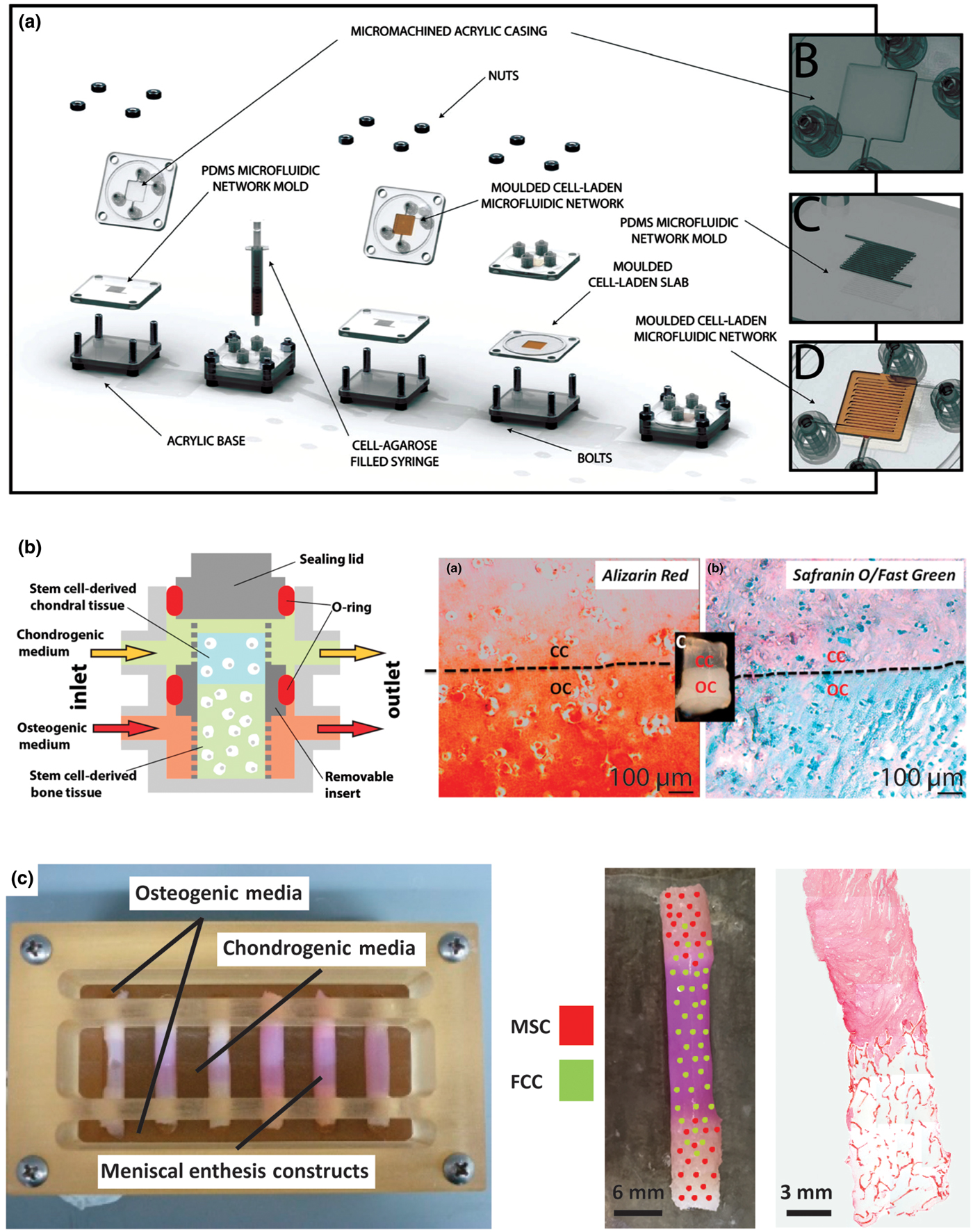
Many of the relevant published systems have been produced for the osteochondral interface, given its similarity to other soft tissue-to-bone interfaces. The majority of systems designed to promote interface formation in culture rely on diffusion-based bioreactors; the general principle being that bone phenotype-promoting media and soft tissue phenotype-promoting media will diffuse through the construct, meet in the middle, and facilitate the formation of an interface.[Reference Chang, Lin, Lin, Chou and Liu61, Reference Grayson, Bhumiratana, Grace Chao, Hung and Vunjak-Novakovic164, Reference Goldman and Barabino165, Reference Li, Qu, Han, Mauck, Han and Ph171] Using this concept, a microfluidic bioreactor directed MSC differentiation along osteogenic and chondrogenic pathways in parallel [Fig. 7(a)]. The bioreactor consisted of an MSC-seeded agarose gel sandwiched between two other MSC-seeded agarose gels that contained channels. The channel-containing gels are perfused with osteogenic and chondrogenic media, respectively, creating a tri-layered scaffold with an interfacial region. This system produced gradients from the osteogenic to chondrogenic regions: decreasing type I collagen content, increasing type II collagen content, and decreasing Alizarin Red staining, reflecting decreasing matrix-immobilized calcium content. These gradients indicate that interfacial regions can be formed by supplying one cell type with different medias and flow conditions simultaneously [Fig. 7(a)].[Reference Goldman and Barabino165, Reference Abraham and Haut Donahue1Reference Han, Heo, Driscoll, Delucca, McLeod, Smith, Duncan, Mauck and Elliott72] Flow of chondrogenic and osteogenic media through the top and bottom of a singular osteochondral scaffold, while maintaining media separation around the scaffold using an O-ring, produced distinctive corresponding regions [Fig. 7(b)]. Osteochondral scaffolds were produced by pipetting a chondrogenic, photo-crosslinked, cell-seeded gel onto an osteogenic, photo-crosslinked, cell-seeded gel. Chondrogenic gels consisted of MSC-seeded methacrylated gelatin with hyaluronic acid and a photo-crosslinker (lithium phenyl-2,4,6-trimethylbenzoylphosphinate). Osteogenic gels had a similar composition, except with hydroxyapatite rather than hyaluronic acid. After 4 weeks of culture, the corresponding sections of the osteochondral construct showed heightened expression of chondrogenic and osteogenic markers. The construct also contained a junction between the sections of the scaffold, with visible GAG staining in the chondrogenic portion and calcium staining in the osteogenic portion [Fig. 7(b)].[Reference Lin, Lozito, Alexander, Gottardi and Tuan163]
Examples of bioreactor designs for maturation of tissue engineering interfacial tissues. (a) Osteochondral microfluidic bioreactor.[Reference Goldman and Barabino172] This bioreactor creates two microchannel arrays in a gel, separated by a non-channel gel slab in the center. Osteogenic and chondrogenic media are flowed through the microchannels allowing for diffusion into surrounding walls and through central slab, creating an interfacial construct. Reprinted with permission from Stephen M. Goldman, Gilda A. Barabino, Cultivation of agarose-based microfluidic hydrogel promotes the development of large, full-thickness, tissue-engineered articular cartilage constructs, John Wiley and Sons. Copyright © 2014 John Wiley & Sons Ltd.[Reference Goldman and Barabino172] (b) Osteochondral bioreactor.[Reference Lin, Lozito, Alexander, Gottardi and Tuan163] Chondrogenic and osteogenic media are continuously flowed through a scaffold, while maintaining separation of media baths through use of an O-ring. Histology shows interfacial region for construct: chondral component (CC) and osseous component (OC). Alizarin red stains for calcium, Safranin-O stains for negatively charged molecules (GAGs), and fast green stains for proteins. This schematic was reprinted from <http://pubs.acs.org/doi/abs/10.1021/mp500136b>. Further permissions related to the material excerpted should be directed to the ACS.[Reference Lin, Lozito, Alexander, Gottardi and Tuan163] (c) Combination mechanical, chemical, and co-culture bioreactor for culturing meniscal enthesis constructs. These constructs consist of two bone plugs seeded with mesenchymal stem cells (MSCs) injected and connected with a high density collagen gel embedded with meniscal fibrochondrocytes (FCCs). The bone plugs are anchored down in the bioreactor using the walls, and then osteogenic media and meniscal media can be applied to different portions of the scaffold. Image shows distribution of co-cultured cells on constructs, and histology shows the morphology of the interfacial region of the construct (images courtesy of Leanne Iannucci). Reprinted from Acta Biomaterialia, Volume 56, Mary Clare McCorry, Melissa M. Mansfield, Xiaozhou Sha, Daniel J. Coppola, Jonathan W. Lee, Lawrence J. Bonassar, A model system for developing a tissue engineered meniscal enthesis, 110–117, Copyright © 2016, with permission from Elsevier[Reference McCorry, Mansfield, Sha, Coppola, Lee and Bonassar60]
Mechanically driven maturation
The native enthesis sustains dynamic tensile, compressive, and shear loading that contributes to the development of the integrated regions. The structural transition from soft tissue-to-bone promotes gradual load transfer across the interface, indicating the importance of the structure–function relationship in the enthesis.[Reference Abraham and Haut Donahue1, Reference Moffat, Sun, Pena, Chahine, Doty, Ateshian, Hung and Lu26, Reference Thomopoulos, Marquez, Weinberger, Birman and Genin173] The native enthesis contains a dense network of collagen fibers interdigitated into bone that aid in tensile and compressive load transmission.[Reference Villegas, Hansen, Liu and Haut Donahue174–Reference Hu, Birman, Demyier-Black, Schwartz, Thomopoulos and Genin177] The loading environment of the enthesis provides mechanical cues to cells that instruct matrix production and remodeling. Lack of loading during native development results in impaired mineral deposition and disorganized fiber distribution.[Reference Kim, Galatz, Patel, Das and Thomopoulos178] In the case of healing after tendon injury, immobilization actually increased structural, compositional, and viscoelastic properties compared with an exercised group.[Reference Thomopoulos, Williams and Soslowsky179] Considering the mechanical influences on tissue development is important when designing methods for tissue engineered enthesis maturation.
During development, anchoring of the meniscus to the tibia produces a static mechanical boundary condition that triggers longitudinal fiber organization in the soft tissue.[Reference Gardner and O'Rahilly90–Reference Mérida-Velasco, Sánchez-Montesinos, Espín-Ferra, Rodríguez-Vázquez, Mérida-Velasco and Jiménez-Collado92, Reference Clark and Ogden180] Mimicking this static mechanical boundary condition has shown organized fiber remodeling from several cell types including fibroblasts,[Reference Huang, Chang, Aggarwal, Lee and Ehrlich181–Reference Costa, Lee and Holmes184] MSCs,[Reference Nirmalanandhan, Levy, Huth and Butler185–Reference Awad, Butler, Harris, Ibrahim, Wu, Young, Kadiyala and Boivin187] cardiomyocytes,[Reference Costa, Lee and Holmes184] annulus fibrosis chondrocytes,[Reference Bowles, Williams, Zipfel and Bonassar188] and meniscal fibrochondrocytes.[Reference McCorry, Mansfield, Sha, Coppola, Lee and Bonassar60, Reference Puetzer, Koo and Bonassar74, Reference McCorry and Bonassar86] Mechanical anchoring at the bony ends of a soft tissue-to-bone model system directed longitudinal fiber formation as well as formed interdigitated fibers at the collagen–bone interface [Fig. 7(c)].[Reference McCorry, Mansfield, Sha, Coppola, Lee and Bonassar60] Cell monolayers mechanically fixed at the end points contracted the cell sheet into a 3D construct. Using this method, the cells organized a highly aligned and integrated enthesis for ACL repair [Fig. 6(b)].[Reference Ma, Smietana, Kostrominova, Wojtys, Larkin and Arruda68] While mechanically directed fiber remodeling has been shown in several systems, different cell types have also displayed varying levels of remodeling capability. When tendon and meniscal fibrochondrocytes were embedded in a collagen matrix and clamped, fibrochondrocytes formed significantly larger fibers than tendon cells.[Reference Puetzer, Sallent, Gelmi and Stevens189] MSCs in a tissue engineered meniscus also showed decreased fiber alignment and diameter compared with fibrochondrocytes.[Reference McCorry and Bonassar86] These studies indicate that the response to mechanical stimuli is highly dependent on cell type.
Active mechanical loading is applied to enthesis tissues in vivo, and these active mechanical signals guide differential tissue formation. While active mechanical loading has not been applied to in vitro enthesis tissue engineering yet, other systems have utilized active loading. Bioreactors have been designed to apply uniaxial tensile loads in bulk ligament and tendon tissue engineering (constructs excluding an enthesis).[Reference Lee, Shin, Cho, Kang, Kim, Park and Shin103, Reference Subramony, Dargis, Castillo, Azeloglu, Tracey, Su and Lu104] After tensile loading of an aligned scaffold seeded with MSCs, type I and III collagen expression increased as did expression of fibroblastic markers, including tenascin-C, fibronectin, and integrins α 2, α 5, and β 1.[Reference Subramony, Dargis, Castillo, Azeloglu, Tracey, Su and Lu104] Simultaneous tensile and compressive stimulation by compressively loading a self-assembled meniscus ring, resulted in significant increases in mechanical and biochemical properties.[Reference Huey and Athanasiou190] This effect was further demonstrated by loading mechanically anchored tissue engineered menisci. Dynamic compressive loading of the meniscus enhanced organized collagen fiber formation, mechanical properties, and GAG accumulation. Mimicking native mechanical loads guided heterogeneous tissue development, where tensile loads in the outer meniscus produced a fiber-containing, collagen-rich tissue, and compressive loads on the inner meniscus increased GAG development.[Reference Puetzer and Bonassar191] The native environment can also serve as a natural load inducer to guide tissue maturation, assuming the construct is robust enough for implantation. A cell self-assembled bone–ligament–bone construct underwent marked increases in collagen content and alignment as well as increases in stiffness after implantation, driving biochemical content and mechanical properties toward native ACL.[Reference Ma, Smietana, Kostrominova, Wojtys, Larkin and Arruda68] These studies collectively support active mechanical stimulation as a useful tool to the drive structural development of tissue engineered constructs.
Looking forward
The field of orthopedic interfacial tissue engineering presents a number of exciting opportunities for pushing forward the fields of biomaterials, tissue engineering, and biomechanics. In the coming years, advances are required in our understanding of both the in vivo function and generation of entheses, as well as in our capabilities to engineer constructs to replace these complex tissues. Specifically, we have identified three areas of opportunity to inform the design and development of next generation tissue engineered entheses: (1) understanding the development and homeostasis of the native enthesis, (2) development of new materials and bioreactors for enthesis engineering, and (3) mechanical and structural verification of tissue engineering and implant success.
1. Understanding the Development and Homeostasis of Native Entheses
(a) Structure–function relationships, specifically at the length scales critical for the function of this hierarchically structured tissue (Fig. 3), remain poorly understood in the native enthesis. Improving our understanding of how specific molecular, cellular, and architectural features contribute to the healthy function of entheses, requires correlative compositional and mechanical data collected with micrometer-scale resolution. In addition to high-resolution data sets, these measurements need to be performed on hydrated tissue samples under physiologically relevant conditions. This type of characterization will require the development of creative imaging strategies that correlatively combine multiple techniques capable of providing chemical, structural, and mechanical information on the same piece of tissue.[Reference Hendley, Tao, Kunitake, De Yoreo and Estroff192]
(b) Various proteins and molecules are present in low concentrations throughout the regions of the enthesis (e.g., non-collagenous proteins in bone, type X collagen in mineralized cartilage, SLRPs in areas with oriented collagen fiber bundles), but the specific functional roles of these macromolecules are largely unknown. For example, the exact function of non-collagenous proteins in bone is unknown given the redundant roles of these proteins in bone formation. Therefore, the cause of irregularities is hard to characterize using knockout models of non-collagenous proteins.[Reference Nudelman, Lausch, Sommerdijk and Sone39] Studies examining the roles of these molecules in the formation of these regional structures, either through knockout models or in vitro concentration studies, will allow for tissue engineers to target specific results (fibers with controlled diameters, fibrocartilage formation, etc.) to create integrated, biomimetic constructs.
(c) Tendon, ligament, cartilage, and bone cell phenotypes have been well characterized independently (Fig. 4), but the enthesis incorporates these phenotypes in overlapping gradients, which makes specific phenotypic categorization challenging. Spatial characterization of cell phenotypes within the enthesis is needed to define concrete objectives regarding cell seeding and localized stem cell differentiation. While differentiation into bone and cartilage is well studied, less is known about appropriate inputs for fibrochondrocyte and hypertrophic fibrochondrocyte differentiation.
(d) Growth factors play an essential role in the development and maintenance of the enthesis; however, limited information exists regarding spatial and temporal expression of growth factors in developing and mature entheses. Additionally, growth factors have complex interactions with each other and the ECM that complicate the study of each one's exact role. Further study should focus on characterizing the spatial and temporal frequencies of expression of growth factors in vivo, thereby generating a greater understanding of the time- and length-scales over which growth factors must be applied to drive cellular differentiation in tissue engineered constructs.
2. Develop New Materials and Bioreactors for Entheses Engineering
(a) Hierarchical structures within the native tissue give rise to mechanical, cellular, and biochemical cues critical to healthy tissue function. However, generating biomaterials with similar types of hierarchical structuring remains a challenge and requires extensive control over assembly at various length scales. New synthetic approaches need to be developed that can create materials with the critical features of the native tissue (e.g., strategic biomimicry) and that are scalable.[Reference Wegst, Bai, Saiz, Tomsia and Ritchie66] This task can only be accomplished by both understanding the native structures and evaluating which features are critical for a given function. Once key hierarchical structures are identified and synthetic methods have been developed, then new biomaterials can be designed to possess many of the same properties that native tissue benefits from in vivo.
(b) The range of materials properties (e.g., several orders of magnitude change in stiffness on the order of <1 mm) in the enthesis presents unique challenges in creating a graded interface. In order for a tissue engineered construct to be mechanically robust, differing materials must be fully integrated, utilizing concentration gradients, interpenetrating materials, etc., to avoid stress concentrators at the point of material interface. A specific challenge in this regard is the design of structures with partially mineralized collagen fibers or gradients in alignment and fiber diameter to help anchor soft tissue to bone.
(c) Current designs of bioreactors for interfacial tissue constructs have been utilized to apply spatially controlled stimuli (Fig. 7). However, the effects of changing the application profile, e.g., a linear gradient versus a step function, of a chemical stimulus on a tissue engineered construct are not well understood. Moving forward, researchers should focus on finer spatial control. Such experiments will increase understanding of the interactions of different chemical stimuli, leading to more refined systems for controlling local cellular behavior.
3. Improve Mechanical and Structural Verification of Tissue Engineering and Implant Success
(a) The baseline mechanical properties (e.g., toughness, stiffness, and failure strain) required for enthesis construct implantation have not been identified. Baseline properties are largely unknown and likely vary significantly with anatomic location. Such mechanical benchmarks would provide engineers with a more concrete goal to work towards when developing constructs. Devices for measuring native load distributions exist,[Reference Wang, Gee, Hutchinson, Stoner, Warren, Chen and Maher193] and similar devices should be developed and utilized in these systems to inform design criteria.
(b) The mechanical behavior of the enthesis is non-linear and heterogeneous. As such, properties and test protocols used to describe the mechanics of linear elastic materials do not fully describe the behavior of these tissues. For example, cyclic loading would provide information on viscoelastic properties (e.g., storage modulus, loss modulus, and hysteresis) and would provide information on the fatigue life of such constructs. Tissue is frequently loaded cyclically in vivo, following gait cycles or other repetitive motions. Therefore, the properties of these tissues during cyclic loading need to be explored to validate implant viability.
(c) In addition to mechanical characterization, analysis of the structure of the enthesis provides a great opportunity for the development of new techniques. The presence of orientation and heterogeneity necessitates the development or adaptation of techniques to highlight these features. Advances in magnetic resonance imaging of soft tissues includes pulse sequences such as ultrashort T2 echo times that highlight collagen orientation,[Reference Ross, Williams, Schnabel, Mohammed, Potter, Bradica, Castiglione, Pownder, Satchell, Saska and Fortier194] but these techniques have not been applied to assess the structure or health of entheses. Additionally, while standard histological analyses enable semi-quantitative assessment of spatial patterns of the components of the enthesis, mapping mineral, proteoglycan, and collagen requires different tissue processing methods, distinct stains, and multiple sections. Vibrational microspectroscopy methods enable detection of multiple chemical species at once through infrared absorption and Raman scattering. These techniques have been more frequently applied to bone, cartilage, tendon, and ligament than the entheses.[Reference Spalazzi, Boskey, Pleshko and Lu12, Reference Schwartz, Pasteris, Genin, Daulton and Thomopoulos42, Reference Khanarian, Boushell, Spalazzi, Pleshko, Boskey and Lu195, Reference Mansfield, Moger, Green, Moger and Winlove196]
As we capitalize on these opportunities and begin to answer these outstanding questions, we will increase our understanding of the native enthesis and, in return, be able to design the next generation of tissue engineered orthopeadic interfaces. Emerging technologies, such as gene therapy and induced pluripotent stem cells (iPSCs),[Reference Phillips, Burns, Le Doux, Guldberg and García105] provide new possibilities for engineering complex tissues. iPSCs are a clinically available cell source; however, precise control of cell differentiation remains a challenge.[Reference Yamanaka197] Gene therapy potentially allows for more direct control of cell differentiation, which is highly pertinent in systems containing many cell types. Other similar technologies, like CRISPR,[Reference Lander198] have been unexplored in orthopedic systems and may be of great value for spatially guiding local differentiation to achieve desired phenotypic gradients. Additionally, as tissue engineering is a relatively new field, many of the materials processing methods that have been developed for other materials systems (electronic, structural, etc.) have not been applied to biologic systems. For example, the electronics industry has demonstrated nanometer-scale control over semiconductor systems using lithography. Some of these technologies have been translated to biologic systems,[Reference Choi, Cabodi, Held, Gleghorn, Bonassar and Stroock199] but the requirement of 3D structuring makes application of these techniques difficult. Other cutting edging processing methods, such as 3D printing,[Reference Jose, Rodriguez, Dixon, Omenetto and Kaplan200] have been utilized to develop complex geometries for tissue engineering, but printing resolution needs to be improved in order to gain clinical viability for these constructs. Utilizing materials design principles external to the biologic fields could greatly benefit implant production. In the next 10 years, we will be able to demonstrate control over the assembly and culture of hierarchically structured living tissues for the repair of orthopedic soft tissue-to-bone interfaces.
Acknowledgments
The authors acknowledge support from the National Center for Advancing Translational Sciences (NCATS) grant TL1TR000459 of the Clinical and Translational Science Center at Weill Cornell Medical College, and A.J.B. acknowledges a pre-doctoral fellowship award (F31AR070009) from the National Institute of Arthritis and Musculoskeletal and Skin Diseases (NIAMS) of the National Institutes of Health (NIH). The authors would like to thank Leanne Iannucci, Benjamin Cohen, and Jongkil Kim for critical reading of the manuscript and Mary Lou Norman for preparing histological sections.


