





1 Introduction
X-ray lasers are useful for probing the internal structures of complex materials and the dynamics of microscopic processes, such as in materials characterization[
Reference Brown, Losko, Carpenter, Clausen, Cooley, Livescu, Kenesei, Park, Stockman and Strantza
1
–
Reference de F. Silveira, Fechte-Heinen and Epp
4
] and biomolecular imaging[
Reference Chapman, Fromme, Barty, White, Kirian, Aquila, Hunter, Schulz, DePonte, Weierstall, Doak, Maia, Martin, Schlichting, Lomb, Coppola, Shoeman, Epp, Hartmann, Rolles, Rudenko, Foucar, Kimmel, Weidenspointner, Holl, Liang, Barthelmess, Caleman, Boutet, Bogan, Krzywinski, Bostedt, Bajt, Gumprecht, Rudek, Erk, Schmidt, Hömke, Reich, Pietschner, Strüder, Hauser, Gorke, Ullrich, Herrmann, Schaller, Schopper, Soltau, Kühnel, Messerschmidt, Bozek, Hau-Riege, Frank, Hampton, Sierra, Starodub, Williams, Hajdu, Timneanu, Seibert, Andreasson, Rocker, Jönsson, Svenda, Stern, Nass, Andritschke, Schröter, Krasniqi, Bott, Schmidt, Wang, Grotjohann, Holton, Barends, Neutze, Marchesini, Fromme, Schorb, Rupp, Adolph, Gorkhover, Andersson, Hirsemann, Potdevin, Graafsma, Nilsson and Spence
5
–
Reference Schunck, Döring, Rösner, Buck, Engel, Miedema, Mahatha, Hoesch, Petraru, Kohlstedt, Schüssler-Langeheine, Rossnagel, David and Beye
7
]. In particular, high-intensity X-ray lasers can also be used to drive chip-size particle acceleration and explore vacuum birefringence physics[
Reference Tajima
8
,
Reference Shen, Bu, Xu, Xu, Ji, Li and Xu
9
]. As a fundamental optical property in light–matter interaction, precise and/or tunable control of the polarization is often essential[
Reference Chakhalian, Freeland, Srajer, Strempfer, Khaliullin, Cezar, Charlton, Dalgliesh, Bernhard, Cristiani, Habermeier and Keimer
10
–
Reference Ueda, García-Fernández, Agrestini, Romao, Van Den Brink, Spaldin, Zhou and Staub
12
]. However, existing X-ray polarization converters usually operate for low-power conditions with characteristic trade-offs. For example, undulator-based systems (e.g., delta/elliptical undulators in the soft X-ray free-electron laser, SXFEL) achieve high polarization[
Reference Lutman, MacArthur, Ilchen, Lindahl, Buck, Coffee, Dakovski, Dammann, Ding, Dürr, Glaser, Grünert, Hartmann, Hartmann, Higley, Hirsch, Levashov, Marinelli, Maxwell, Mitra, Moeller, Osipov, Peters, Planas, Shevchuk, Schlotter, Scholz, Seltmann, Viefhaus, Walter, Wolf, Huang and Nuhn
13
,
Reference Gao, Deng, Liu and Wang
14
] with femtosecond pulse capability and two-color operation, but are constrained to soft X-rays, large footprints ( $>10$
m) and slow switching (
$>10$
m) and slow switching ( $\sim$
ms). Diamond X-ray phase retarders (XPRs) offer compact design and can realize circular polarization through birefringence modulation with sub-ms switching, yet suffer from low conversion efficiency and discrete tuning[
Reference Suzuki, Inubushi, Yabashi and Ishikawa
15
].
$\sim$
ms). Diamond X-ray phase retarders (XPRs) offer compact design and can realize circular polarization through birefringence modulation with sub-ms switching, yet suffer from low conversion efficiency and discrete tuning[
Reference Suzuki, Inubushi, Yabashi and Ishikawa
15
].
Recent advances in X-ray lasers have seen dramatic increases in both intensity and power. Multiple approaches have been proposed to generate multiterawatt (TW) X-ray pulses at X-ray free-electron laser (XFEL) facilities[
Reference Emma, Fang, Wu and Pellegrini
16
–
Reference Prat and Reiche
18
], including high-order-harmonic generation (HHG) from laser–solid interactions, which has demonstrated the potential to produce isolated $100$
-TW X-ray pulses[
Reference Xu, Zhang, Zhang, Lu, Zhou, Zhou, Dromey, Zhu, Zepf, He and Qiao
19
]. In addition, recently proposed X-ray laser focusing schemes[
Reference Chen, Huang, Jiang, Yu and Zhou
20
,
Reference Chen, Huang, Jiang, Wu, Yu and Zhou
21
] show promise for generating relativistic-intensity X-ray outputs. To date, hard X-ray (i.e., very short wavelength) XFELs can be focused to a 7 nm spot at
$100$
-TW X-ray pulses[
Reference Xu, Zhang, Zhang, Lu, Zhou, Zhou, Dromey, Zhu, Zepf, He and Qiao
19
]. In addition, recently proposed X-ray laser focusing schemes[
Reference Chen, Huang, Jiang, Yu and Zhou
20
,
Reference Chen, Huang, Jiang, Wu, Yu and Zhou
21
] show promise for generating relativistic-intensity X-ray outputs. To date, hard X-ray (i.e., very short wavelength) XFELs can be focused to a 7 nm spot at ${10}^{22}\kern0.1em \mathrm{W}/{\mathrm{cm}}^2$
intensity[
Reference Yamada, Matsuyama, Inoue, Osaka, Inoue, Nakamura, Tanaka, Inubushi, Yabuuchi, Tono, Tamasaku, Yumoto, Koyama, Ohashi, Yabashi and Yamauchi
22
]. The dramatic increase in X-ray power and intensity makes conventional polarizers (e.g., undulators, diamond XPRs) more prone to damage, necessitating significantly enhanced damage resistance in polarization optics. To avoid optical damage by high-power, high-intensity lasers in applications, plasma-based components such as plasma mirrors[
Reference Thaury, Quéré, Geindre, Levy, Ceccotti, Monot, Bougeard, Réau, d’Oliveira, Audebert, Marjoribanks and Martin
23
–
Reference Kim, Kim, Park, Kwon, Yeom, Cho, Kwon, Yun, Sung, Lee, Luu, Nam and Kim
25
], plasma refractors[
Reference Seemann, Wan, Tata, Kroupp and Malka
26
], plasma lenses[
Reference Wang, Lin, Sheng, Liu, Zhao, Guo, Lu, He, Chen and Yan
27
,
Reference Ji, Snyder, Pukhov, Freeman and Akli
28
], plasma switches[
Reference Palaniyappan, Hegelich, Wu, Jung, Gautier, Yin, Albright, Johnson, Shimada, Letzring, Offermann, Ren, Huang, Hörlein, Dromey, Fernandez and Shah
29
] and plasma amplifiers[
Reference Trines, Fiuza, Bingham, Fonseca, Silva, Cairns and Norreys
30
,
Reference Lei, Sheng, Weng, Chen and Zhang
31
] have been proposed. These plasma devices themselves are resistant to optical damage, providing a promising alternative to address the problem of polarization control of high-power X-ray lasers.
${10}^{22}\kern0.1em \mathrm{W}/{\mathrm{cm}}^2$
intensity[
Reference Yamada, Matsuyama, Inoue, Osaka, Inoue, Nakamura, Tanaka, Inubushi, Yabuuchi, Tono, Tamasaku, Yumoto, Koyama, Ohashi, Yabashi and Yamauchi
22
]. The dramatic increase in X-ray power and intensity makes conventional polarizers (e.g., undulators, diamond XPRs) more prone to damage, necessitating significantly enhanced damage resistance in polarization optics. To avoid optical damage by high-power, high-intensity lasers in applications, plasma-based components such as plasma mirrors[
Reference Thaury, Quéré, Geindre, Levy, Ceccotti, Monot, Bougeard, Réau, d’Oliveira, Audebert, Marjoribanks and Martin
23
–
Reference Kim, Kim, Park, Kwon, Yeom, Cho, Kwon, Yun, Sung, Lee, Luu, Nam and Kim
25
], plasma refractors[
Reference Seemann, Wan, Tata, Kroupp and Malka
26
], plasma lenses[
Reference Wang, Lin, Sheng, Liu, Zhao, Guo, Lu, He, Chen and Yan
27
,
Reference Ji, Snyder, Pukhov, Freeman and Akli
28
], plasma switches[
Reference Palaniyappan, Hegelich, Wu, Jung, Gautier, Yin, Albright, Johnson, Shimada, Letzring, Offermann, Ren, Huang, Hörlein, Dromey, Fernandez and Shah
29
] and plasma amplifiers[
Reference Trines, Fiuza, Bingham, Fonseca, Silva, Cairns and Norreys
30
,
Reference Lei, Sheng, Weng, Chen and Zhang
31
] have been proposed. These plasma devices themselves are resistant to optical damage, providing a promising alternative to address the problem of polarization control of high-power X-ray lasers.
In this paper, we propose using a solid-density plasma plate for tailoring the polarization of ultrashort, high-power and high-intensity X-ray laser pulses. Since the refractive index of the solid-density plasma for X-ray lasers is less than unity, the vacuum–plasma interface can serve as a total internal reflection (TIR) surface[
Reference Carniglia and Brownstein
32
]. Laser light incident on the plasma surface at a greater angle than the critical angle ${\theta}_\mathrm{c}$
will be totally reflected. As the reflection is accompanied by phase and polarization shifts of the light, by tailoring the laser wavelength, angle of incidence and/or plasma electron density, one can achieve continuous tuning of its polarization, including linear, elliptical and circular polarization, and this tuning process is linear. We analytically estimate and particle-in-cell simulate tailored mode conversion of short-pulse X-ray laser light using solid-density plasmas. It is found that for
${\theta}_\mathrm{c}$
will be totally reflected. As the reflection is accompanied by phase and polarization shifts of the light, by tailoring the laser wavelength, angle of incidence and/or plasma electron density, one can achieve continuous tuning of its polarization, including linear, elliptical and circular polarization, and this tuning process is linear. We analytically estimate and particle-in-cell simulate tailored mode conversion of short-pulse X-ray laser light using solid-density plasmas. It is found that for ${10}^{18}-{10}^{22}\ \mathrm{W}/{\mathrm{cm}}^2$
(or
${10}^{18}-{10}^{22}\ \mathrm{W}/{\mathrm{cm}}^2$
(or $0.01-1$
TW) femtosecond X-ray laser pulses, over
$0.01-1$
TW) femtosecond X-ray laser pulses, over $95\%$
and nearly
$95\%$
and nearly $100\%$
efficiency of X-ray polarization conversion is possible. Moreover, this method potentially offers distinct advantages: compact size, high conversion efficiency, ultrafast polarization modulation (sub-ps) and no damage threshold – making it a reliable solution for demanding applications in high-power X-ray laser systems.
$100\%$
efficiency of X-ray polarization conversion is possible. Moreover, this method potentially offers distinct advantages: compact size, high conversion efficiency, ultrafast polarization modulation (sub-ps) and no damage threshold – making it a reliable solution for demanding applications in high-power X-ray laser systems.
2 Model analysis
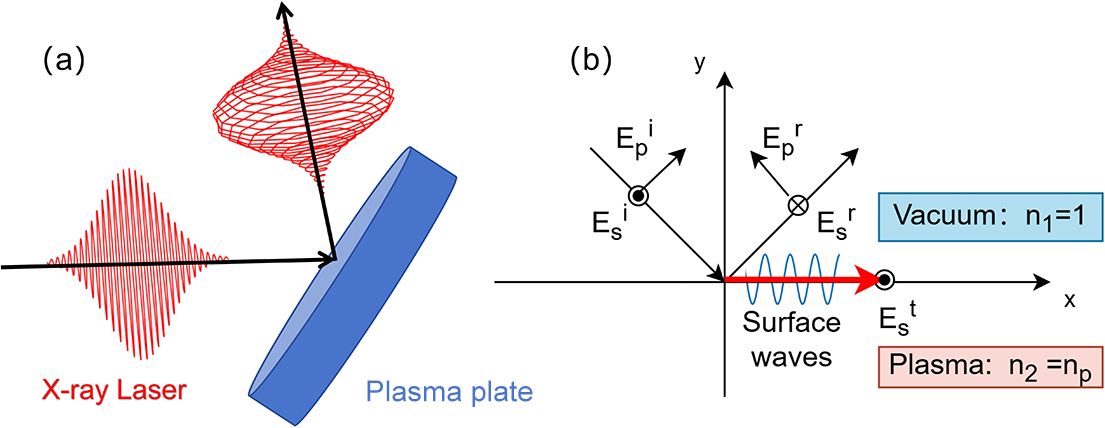
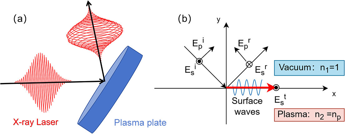
Figure 1 shows the X-ray polarization converter based on linear TIR. The X-ray laser pulse is obliquely incident on the surface of a solid-density plasma with a refractive index less than unity. TIR occurs[
Reference Carniglia and Brownstein
32
,
Reference Liu, Chen, Parrott, Ung, Xu and Pickwell-MacPherson
33
] if the incident angle ${\theta}_{\mathrm{i}}$
exceeds the critical angle
${\theta}_{\mathrm{i}}$
exceeds the critical angle ${\theta}_{\mathrm{c}}=\arcsin \left({n}_2/{n}_1\right)=\arcsin \left({n}_\mathrm{p}\right)$
, where
${\theta}_{\mathrm{c}}=\arcsin \left({n}_2/{n}_1\right)=\arcsin \left({n}_\mathrm{p}\right)$
, where ${n}_1=1$
and
${n}_1=1$
and ${n}_2={n}_{\mathrm{p}}<1$
are the refractive indices of the vacuum and plasma, respectively. This process is governed by the Fresnel equations, which describe the amplitude and phase relationships of the reflected and transmitted waves at interfaces. Under the boundary continuity condition (i.e., matching of electromagnetic field components at the interface), TIR induces not only incident and reflected waves but also evanescent waves penetrating the plasma medium. This surface wave acts as an energy buffer, temporarily storing and redistributing energy flux to maintain conservation during the TIR[
Reference Milosevic
34
]. The
${n}_2={n}_{\mathrm{p}}<1$
are the refractive indices of the vacuum and plasma, respectively. This process is governed by the Fresnel equations, which describe the amplitude and phase relationships of the reflected and transmitted waves at interfaces. Under the boundary continuity condition (i.e., matching of electromagnetic field components at the interface), TIR induces not only incident and reflected waves but also evanescent waves penetrating the plasma medium. This surface wave acts as an energy buffer, temporarily storing and redistributing energy flux to maintain conservation during the TIR[
Reference Milosevic
34
]. The $x$
and
$x$
and $y$
components of the laser’s Poynting vector of the surface wave are as follows:
$y$
components of the laser’s Poynting vector of the surface wave are as follows:
 $$\begin{align}{S}_{\mathrm{P}x}&=-\frac{k_\mathrm{t}}{2w}\left(\frac{\sin {\theta}_{\mathrm{i}}}{n_{\mathrm{p}}}\right){D}_0^2\left(1+\cos \left(2\left({k}_\mathrm{t}\frac{\sin {\theta}_{\mathrm{i}}}{n_{\mathrm{p}}}x-\omega t\right)\right)\right),\end{align}$$
 $$\begin{align}{S}_{\mathrm{P}y}&=\frac{k_\mathrm{t}}{2w}\sqrt{\frac{\sin^2{\theta}_{\mathrm{i}}}{n_{\mathrm{p}}^2}-1}\;{D}_0^2\sin 2\left({k}_\mathrm{t}\frac{\sin {\theta}_{\mathrm{i}}}{n_{\mathrm{p}}}x-\omega t\right),\end{align}$$
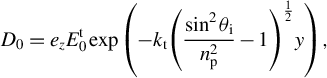 $$\begin{align}{D}_0&={e}_z{E}_0^\mathrm{t}\exp \left(-{k}_\mathrm{t}{\left(\frac{\sin^2{\theta}_{\mathrm{i}}}{n_{\mathrm{p}}^2}-1\right)}^{\frac{1}{2}}y\right),\end{align}$$
(a) Schematic of the proposed scheme. (b) Total internal reflection at the plasma surface. Here, E denotes the electric field, while the superscripts i, t and r denote the incident, refracted and reflected light, respectively. The subscripts s and p denote the s- and p-polarization components of the laser.
where ${k}_\mathrm{t}$
is the wave vector in the
${k}_\mathrm{t}$
is the wave vector in the $x$
-direction,
$x$
-direction, $\omega$
denotes the laser angular frequency and
$\omega$
denotes the laser angular frequency and ${E}_0^\mathrm{t}$
represents the electric field amplitude of the refracted light. Within half a laser period, the energy of the surface wave enters the plasma and is stored in a thin layer near the interface. In the other half of the period, this energy is released and becomes the energy of the reflected wave. However, the average value is zero within the same period. Therefore, during TIR, the instantaneous energy flow in the direction perpendicular to the interface within the penetration depth is not zero, but the average energy flow is zero. That is, the conversion from incident to reflected waves is mediated by the surface wave’s energy oscillation, leading to a phase shift in the reflected polarization states.
${E}_0^\mathrm{t}$
represents the electric field amplitude of the refracted light. Within half a laser period, the energy of the surface wave enters the plasma and is stored in a thin layer near the interface. In the other half of the period, this energy is released and becomes the energy of the reflected wave. However, the average value is zero within the same period. Therefore, during TIR, the instantaneous energy flow in the direction perpendicular to the interface within the penetration depth is not zero, but the average energy flow is zero. That is, the conversion from incident to reflected waves is mediated by the surface wave’s energy oscillation, leading to a phase shift in the reflected polarization states.
In linear TIR, we have $\sin {\theta}_{\mathrm{i}}>{n}_{\mathrm{p}}$
,
$\sin {\theta}_{\mathrm{i}}>{n}_{\mathrm{p}}$
, $\cos {\theta}_{\mathrm{t}}=i\sqrt{\sin^2{\theta}_{\mathrm{i}}/{n}_{\mathrm{p}}^2-1}$
, where
$\cos {\theta}_{\mathrm{t}}=i\sqrt{\sin^2{\theta}_{\mathrm{i}}/{n}_{\mathrm{p}}^2-1}$
, where ${\theta}_{\mathrm{i}}$
and
${\theta}_{\mathrm{i}}$
and ${\theta}_{\mathrm{t}}$
represent the incident and refracted angles, respectively. By substituting the Fresnel equations and performing algebraic manipulations, the following relations can be readily obtained[
Reference Jackson
35
]:
${\theta}_{\mathrm{t}}$
represent the incident and refracted angles, respectively. By substituting the Fresnel equations and performing algebraic manipulations, the following relations can be readily obtained[
Reference Jackson
35
]:
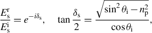 $$\begin{align}\frac{E_{\mathrm{s}}^{\mathrm{r}}}{E_\mathrm{s}^\mathrm{i}}={e}^{-i{\delta}_\mathrm{s}},\kern1em \tan \frac{\delta_\mathrm{s}}{2}=\frac{\sqrt{\sin^2{\theta}_{\mathrm{i}}-{n}_{\mathrm{p}}^2}}{\cos {\theta}_{\mathrm{i}}},\end{align}$$
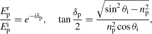 $$\begin{align}\frac{E_\mathrm{p}^\mathrm{r}}{E_\mathrm{p}^\mathrm{i}}={e}^{-i{\delta}_\mathrm{p}},\kern1em \tan \frac{\delta_\mathrm{p}}{2}=\frac{\sqrt{\sin^2{\theta}_{\mathrm{i}}-{n}_{\mathrm{p}}^2}}{n_{\mathrm{p}}^2\cos {\theta}_{\mathrm{i}}},\end{align}$$
where ${E}_\mathrm{s}^\mathrm{i}$
,
${E}_\mathrm{s}^\mathrm{i}$
, ${E}_\mathrm{p}^\mathrm{i}$
,
${E}_\mathrm{p}^\mathrm{i}$
, ${E}_\mathrm{s}^\mathrm{r}$
and
${E}_\mathrm{s}^\mathrm{r}$
and ${E}_\mathrm{p}^\mathrm{r}$
are the electric field amplitudes of the s-polarized (perpendicular to the incident plane) and p-polarized (parallel to the incident plane) components of the incident and reflected light, respectively. It can be seen that the electric field magnitudes of the p- and s-polarized components of the reflected light are the same as that of the incident laser, or
${E}_\mathrm{p}^\mathrm{r}$
are the electric field amplitudes of the s-polarized (perpendicular to the incident plane) and p-polarized (parallel to the incident plane) components of the incident and reflected light, respectively. It can be seen that the electric field magnitudes of the p- and s-polarized components of the reflected light are the same as that of the incident laser, or $\mid {E}_\mathrm{s}^\mathrm{r}\mid =\mid {E}_\mathrm{s}^\mathrm{i}\mid$
,
$\mid {E}_\mathrm{s}^\mathrm{r}\mid =\mid {E}_\mathrm{s}^\mathrm{i}\mid$
, $\mid {E}_\mathrm{p}^\mathrm{r}\mid =\mid {E}_\mathrm{p}^\mathrm{i}\mid$
. However, both undergo phase shifts
$\mid {E}_\mathrm{p}^\mathrm{r}\mid =\mid {E}_\mathrm{p}^\mathrm{i}\mid$
. However, both undergo phase shifts ${\delta}_\mathrm{s}$
and
${\delta}_\mathrm{s}$
and ${\delta}_\mathrm{p}$
relative to incident light, and the phase difference
${\delta}_\mathrm{p}$
relative to incident light, and the phase difference $\delta ={\delta}_\mathrm{p}-{\delta}_\mathrm{s}$
is given by the following:
$\delta ={\delta}_\mathrm{p}-{\delta}_\mathrm{s}$
is given by the following:
 $$\begin{align}\tan \left(\frac{\delta }{2}\right)=\tan \left(\frac{\delta_\mathrm{p}-{\delta}_\mathrm{s}}{2}\right)=\frac{\cos \left({\theta}_{\mathrm{i}}\right)\sqrt{\sin^2\left({\theta}_{\mathrm{i}}\right)-{\left({n}_{\mathrm{p}}\right)}^2}}{\sin^2\left({\theta}_{\mathrm{i}}\right)}.\end{align}$$
In this model, the X-ray laser propagates in a vacuum and undergoes TIR at the plasma surface, enabling conversion of the polarization state. For X-rays, the refractive index in the solid-density plasma is given by ${n}_{\mathrm{p}}=\sqrt{1-{n}_\mathrm{e}/{n}_\mathrm{c}}$
. For a relatively short-wavelength X-ray laser,
${n}_{\mathrm{p}}=\sqrt{1-{n}_\mathrm{e}/{n}_\mathrm{c}}$
. For a relatively short-wavelength X-ray laser, ${n}_\mathrm{e}<{n}_\mathrm{c}$
and
${n}_\mathrm{e}<{n}_\mathrm{c}$
and ${n}_{\mathrm{p}}<1$
, where
${n}_{\mathrm{p}}<1$
, where ${n}_\mathrm{e}$
denotes the electron density, and the critical density
${n}_\mathrm{e}$
denotes the electron density, and the critical density ${n}_\mathrm{c}$
is given by
${n}_\mathrm{c}$
is given by ${n}_\mathrm{c}={m}_\mathrm{e}{\omega}_0^2/4\pi {e}^2={n}_0/{\lambda}_{\mathrm{nm}}^2$
. Here,
${n}_\mathrm{c}={m}_\mathrm{e}{\omega}_0^2/4\pi {e}^2={n}_0/{\lambda}_{\mathrm{nm}}^2$
. Here, ${m}_\mathrm{e}$
is the electron mass,
${m}_\mathrm{e}$
is the electron mass, ${\omega}_0$
is the central angular frequency and
${\omega}_0$
is the central angular frequency and $e$
is the elementary charge. The parameter
$e$
is the elementary charge. The parameter ${n}_0\approx 1.1\times {10}^{33}\;{\mathrm{m}}^{-3}$
, and
${n}_0\approx 1.1\times {10}^{33}\;{\mathrm{m}}^{-3}$
, and ${\lambda}_{\mathrm{nm}}$
is the laser wavelength normalized to nanometers (nm). Letting
${\lambda}_{\mathrm{nm}}$
is the laser wavelength normalized to nanometers (nm). Letting $\alpha \equiv \tan \left(\frac{\delta }{2}\right)$
and substituting the expression of
$\alpha \equiv \tan \left(\frac{\delta }{2}\right)$
and substituting the expression of ${n}_{\mathrm{p}}$
in Equation (6), we get the following:
${n}_{\mathrm{p}}$
in Equation (6), we get the following:
 $$\begin{align}{\lambda}_{\mathrm{nm}}=\sqrt{\frac{n_0}{n_\mathrm{e}}}\times \sqrt{1-{\sin}^2{\theta}_{\mathrm{i}}\left(1-{\alpha}^2{\tan}^2{\theta}_{\mathrm{i}}\right)}.\end{align}$$
This equation describes the relation among the laser wavelength, the incident angle and the phase shift. The value of $\delta$
can range from
$\delta$
can range from $0$
to
$0$
to $\pi /2$
, so that
$\pi /2$
, so that $0<\alpha \le 1$
, where
$0<\alpha \le 1$
, where $\alpha =1$
refers to the conversion from linear to circular polarization. Equation (7) suggests an upper limit of the laser wavelength as
$\alpha =1$
refers to the conversion from linear to circular polarization. Equation (7) suggests an upper limit of the laser wavelength as ${\lambda}_{\mathrm{nm}}<\sqrt{\frac{n_0}{n_\mathrm{e}}}$
, which corresponds to the condition of
${\lambda}_{\mathrm{nm}}<\sqrt{\frac{n_0}{n_\mathrm{e}}}$
, which corresponds to the condition of ${n}_\mathrm{e}<{n}_\mathrm{c}$
. For example, for a solid-density Al plasma with
${n}_\mathrm{e}<{n}_\mathrm{c}$
. For example, for a solid-density Al plasma with ${n}_{\mathrm{e}}=7.8\times {10}^{29}\;{\mathrm{m}}^{-3}$
, this gives an upper limit of
${n}_{\mathrm{e}}=7.8\times {10}^{29}\;{\mathrm{m}}^{-3}$
, this gives an upper limit of $37.5\;\mathrm{nm}$
. Namely, for an X-ray laser with
$37.5\;\mathrm{nm}$
. Namely, for an X-ray laser with ${\lambda}_{\mathrm{nm}}<37.5\;\mathrm{nm}$
, conversion from linear to elliptic (including circular) polarization can be achieved.
${\lambda}_{\mathrm{nm}}<37.5\;\mathrm{nm}$
, conversion from linear to elliptic (including circular) polarization can be achieved.
It is interesting to note that for oblique incidence, the effective critical density for laser reflection is reduced by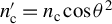 ${n}_\mathrm{c}^{\prime }={n}_\mathrm{c}\cos {\theta}^2$
, where
${n}_\mathrm{c}^{\prime }={n}_\mathrm{c}\cos {\theta}^2$
, where $\theta$
is the incident angle[
Reference Kruer
36
]. This indicates that laser reflection could occur for
$\theta$
is the incident angle[
Reference Kruer
36
]. This indicates that laser reflection could occur for ${n}_\mathrm{e}>{n}_\mathrm{c}^{\prime }$
. For the case of TIR, the critical angle for TIR can be written as
${n}_\mathrm{e}>{n}_\mathrm{c}^{\prime }$
. For the case of TIR, the critical angle for TIR can be written as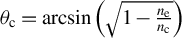 ${\theta}_\mathrm{c}=\arcsin \left(\sqrt{1-\frac{n_\mathrm{e}}{n_\mathrm{c}}}\right)$
. That is, the critical angle corresponds to
${\theta}_\mathrm{c}=\arcsin \left(\sqrt{1-\frac{n_\mathrm{e}}{n_\mathrm{c}}}\right)$
. That is, the critical angle corresponds to ${n}_\mathrm{e}={n}_\mathrm{c}\cos {\theta}_\mathrm{c}^2={n}_\mathrm{c}^{\prime }$
. When the incident angle
${n}_\mathrm{e}={n}_\mathrm{c}\cos {\theta}_\mathrm{c}^2={n}_\mathrm{c}^{\prime }$
. When the incident angle $\theta$
exceeds the critical angle
$\theta$
exceeds the critical angle ${\theta}_\mathrm{c}$
, TIR occurs. This actually also corresponds to the condition of
${\theta}_\mathrm{c}$
, TIR occurs. This actually also corresponds to the condition of ${n}_\mathrm{e}>{n}_\mathrm{c}^{\prime }$
. Thus, these two descriptions actually are equivalent.
${n}_\mathrm{e}>{n}_\mathrm{c}^{\prime }$
. Thus, these two descriptions actually are equivalent.
3 Particle-in-cell simulations
To verify the above scheme, we have performed a two-dimensional (2D) PIC simulation using EPOCH code[
Reference Arber, Bennett, Brady, Lawrence-Douglas, Ramsay, Sircombe, Gillies, Evans, Schmitz, Bell and Ridgers
37
]. Firstly, we demonstrated the feasibility of polarization state conversion, where linearly polarized (LP) X-ray laser pulses can be converted into circularly polarized (CP) or elliptically polarized (EP) laser pulses. The LP X-ray laser pulse is of incident angle ${\theta}_{\mathrm{i}}=41.3{}^{\circ}$
(far exceeding the critical angle of about
${\theta}_{\mathrm{i}}=41.3{}^{\circ}$
(far exceeding the critical angle of about $18.4{}^{\circ}$
for the parameters given here), wavelength of
$18.4{}^{\circ}$
for the parameters given here), wavelength of ${\lambda}_0=36\;\mathrm{nm}$
, (full width at half-maximum) duration of
${\lambda}_0=36\;\mathrm{nm}$
, (full width at half-maximum) duration of $\tau =2.12\;\mathrm{fs}$
and radius of
$\tau =2.12\;\mathrm{fs}$
and radius of $5.6{\lambda}_0$
. The incident light is initially LP and consists of both p-polarized and s-polarized components with identical phase and amplitude. The laser intensity is
$5.6{\lambda}_0$
. The incident light is initially LP and consists of both p-polarized and s-polarized components with identical phase and amplitude. The laser intensity is $I=8\times {10}^{18}\kern0.1em \mathrm{W}/{\mathrm{cm}}^2$
, so that relativistic amplitude of laser
$I=8\times {10}^{18}\kern0.1em \mathrm{W}/{\mathrm{cm}}^2$
, so that relativistic amplitude of laser ${a}_0={eE}_0/{m}_\mathrm{e}{\omega}_0c=0.087$
, where
${a}_0={eE}_0/{m}_\mathrm{e}{\omega}_0c=0.087$
, where ${E}_0$
is the laser amplitude and
${E}_0$
is the laser amplitude and $c$
is the speed of light in vacuum. The laser pulse is focused on the target, which is a fully ionized solid aluminum plasma slab of electron density
$c$
is the speed of light in vacuum. The laser pulse is focused on the target, which is a fully ionized solid aluminum plasma slab of electron density ${n}_{\mathrm{e}}=7.8\times {10}^{29}\kern0.1em {\mathrm{m}}^{-3}$
, or approximately
${n}_{\mathrm{e}}=7.8\times {10}^{29}\kern0.1em {\mathrm{m}}^{-3}$
, or approximately $0.9{n}_\mathrm{c}$
. The initial temperature of the electrons is
$0.9{n}_\mathrm{c}$
. The initial temperature of the electrons is $1\;\mathrm{keV}$
. Such plasma can be experimentally generated by using a double-laser irradiation scheme[
Reference Beier, Allison, Efthimion, Flippo, Gao, Hansen, Hill, Hollinger, Logantha, Musthafa, Nedbailo, Senthilkumaran, Shepherd, Shlyaptsev, Song, Wang, Dollar, Rocca and Hussein
38
], which has led to very homogeneous, micrometer-scale, solid-density plasma with a well-defined structure and temperature ranging from
$1\;\mathrm{keV}$
. Such plasma can be experimentally generated by using a double-laser irradiation scheme[
Reference Beier, Allison, Efthimion, Flippo, Gao, Hansen, Hill, Hollinger, Logantha, Musthafa, Nedbailo, Senthilkumaran, Shepherd, Shlyaptsev, Song, Wang, Dollar, Rocca and Hussein
38
], which has led to very homogeneous, micrometer-scale, solid-density plasma with a well-defined structure and temperature ranging from $0.25$
to
$0.25$
to $2.5\;\mathrm{keV}$
. In this case, the assumption of an ideal plasma is applicable, and the ionization effect of the X-ray laser can also be neglected.
$2.5\;\mathrm{keV}$
. In this case, the assumption of an ideal plasma is applicable, and the ionization effect of the X-ray laser can also be neglected.
The simulation domain extends from $0$
to
$0$
to $120{\lambda}_0$
in the
$120{\lambda}_0$
in the $x$
-direction and from
$x$
-direction and from $-20{\lambda}_0$
to
$-20{\lambda}_0$
to $100{\lambda}_0$
in the
$100{\lambda}_0$
in the $y$
-direction. The simulation uses an ultra-high-resolution 2D grid configuration with
$y$
-direction. The simulation uses an ultra-high-resolution 2D grid configuration with $7680\times 7680$
grid points, a grid spacing of
$7680\times 7680$
grid points, a grid spacing of ${\lambda}_0/64$
(corresponding to 64 points per wavelength) and a high-density particle distribution (
${\lambda}_0/64$
(corresponding to 64 points per wavelength) and a high-density particle distribution ( $10$
particles per grid point). The surface wave skin depth is
$10$
particles per grid point). The surface wave skin depth is ${l}_{\mathrm{skin}}={\lambda}_0/\left(2\pi {n}_{\mathrm{p}}\sqrt{\sin^2{\theta}_{\mathrm{i}}/{n}_{\mathrm{p}}^2-1}\right)\approx 0.94{\lambda}_0$
. The resolution of the simulation is thus much smaller than
${l}_{\mathrm{skin}}={\lambda}_0/\left(2\pi {n}_{\mathrm{p}}\sqrt{\sin^2{\theta}_{\mathrm{i}}/{n}_{\mathrm{p}}^2-1}\right)\approx 0.94{\lambda}_0$
. The resolution of the simulation is thus much smaller than ${l}_{\mathrm{skin}}$
, ensuring that the physical processes in the plasma boundary layer are adequately resolved.
${l}_{\mathrm{skin}}$
, ensuring that the physical processes in the plasma boundary layer are adequately resolved.
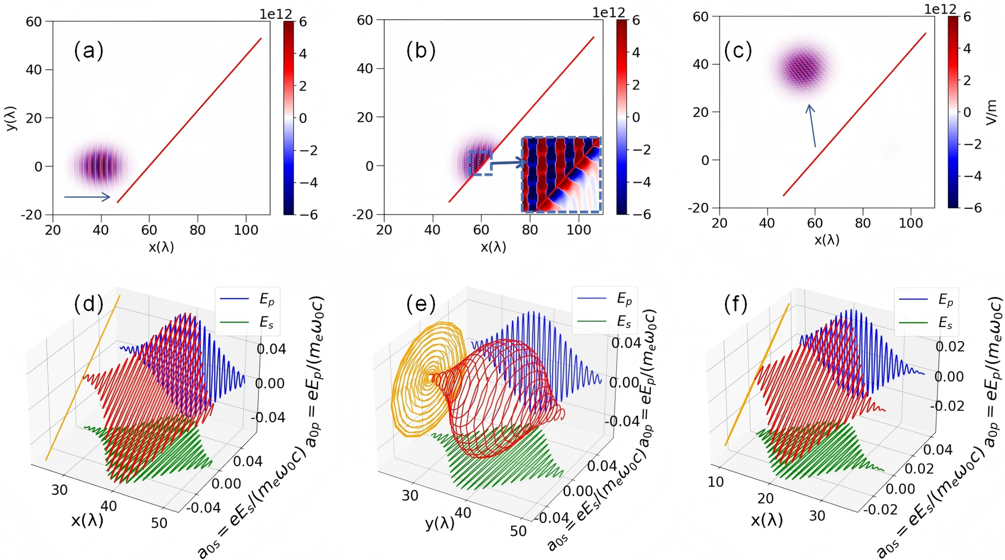
Figure 2(a) shows the electric field distribution of the incident X-ray laser, and Figure 2(b) shows the electric field distribution at the moment of laser–plasma interaction. It can be observed that surface waves moving along the interface exist within the plasma medium. Figure 2(c) shows the electric field distribution of the reflected X-rays. The reflectivity reaches $99.97\%$
, indicating that almost all incident light is reflected. This high reflectivity not only verifies the effectiveness of the polarization conversion mechanism based on TIR, but also holds significant implications for practical applications.
$99.97\%$
, indicating that almost all incident light is reflected. This high reflectivity not only verifies the effectiveness of the polarization conversion mechanism based on TIR, but also holds significant implications for practical applications.
Electric field distributions in the laser–plasma interaction. Electric field of the incident laser pulse at (a) $t=60{T}_0$
and (b) at
$t=60{T}_0$
and (b) at $t=82{T}_0$
, as it reaches the surface. (c) Electric field distribution of the circularly polarized reflected wave at
$t=82{T}_0$
, as it reaches the surface. (c) Electric field distribution of the circularly polarized reflected wave at $t=120{T}_0$
. Electric field on the laser axis of (d) the incident laser and (e) the reflected pulse. In the above, the laser incidence angle is
$t=120{T}_0$
. Electric field on the laser axis of (d) the incident laser and (e) the reflected pulse. In the above, the laser incidence angle is $41.3{}^{\circ}$
. (f) Electric field of the reflected pulse for
$41.3{}^{\circ}$
. (f) Electric field of the reflected pulse for $0{}^{\circ}$
incidence angle. In all the lower panels, the 3D field vector (red), profiles of the two orthogonal field components
$0{}^{\circ}$
incidence angle. In all the lower panels, the 3D field vector (red), profiles of the two orthogonal field components ${E}_\mathrm{s}$
(green) and
${E}_\mathrm{s}$
(green) and ${E}_\mathrm{p}$
(blue) and the projection of
${E}_\mathrm{p}$
(blue) and the projection of ${E}_\mathrm{s}-{E}_\mathrm{p}$
(orange) are displayed.
${E}_\mathrm{s}-{E}_\mathrm{p}$
(orange) are displayed.
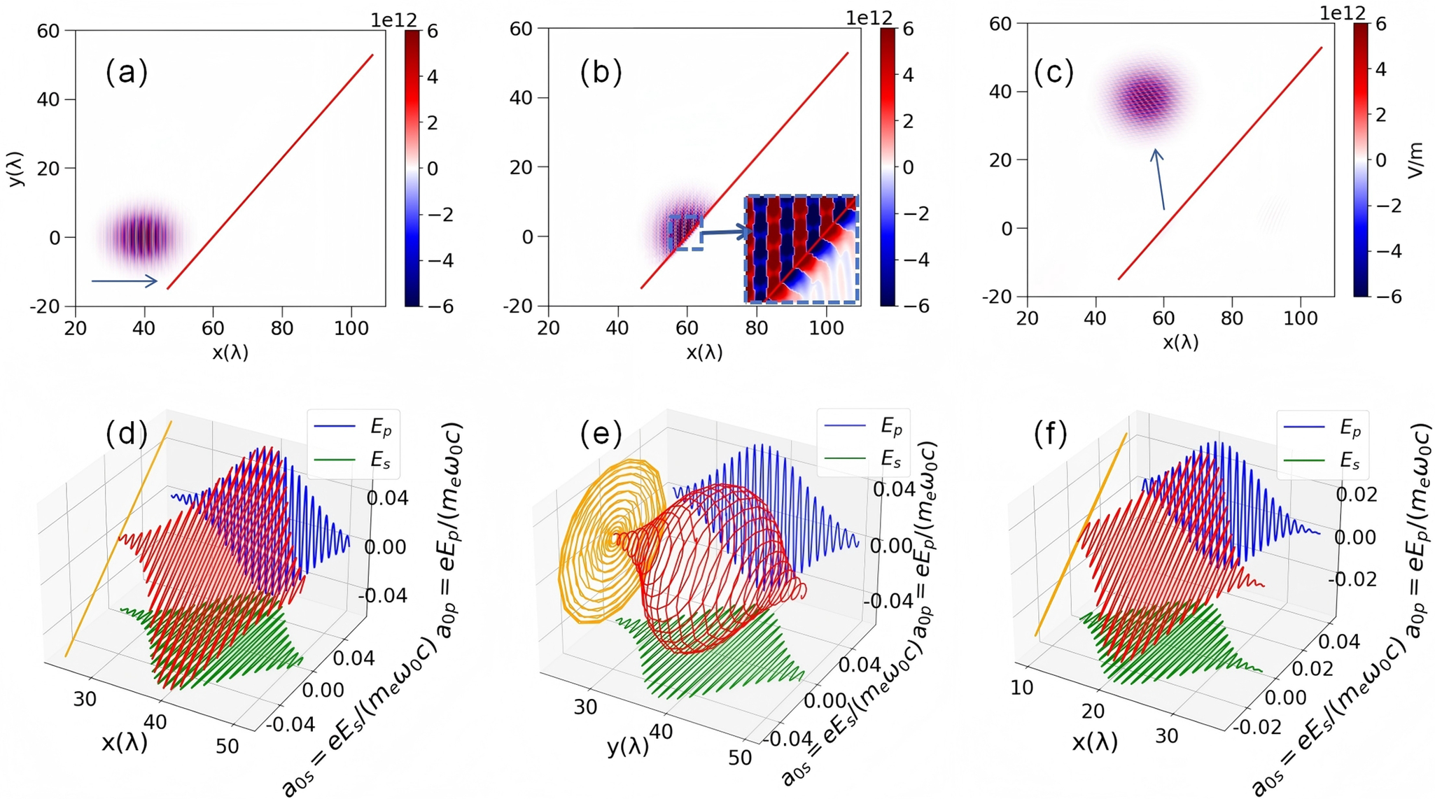
The LP incident laser waveform, as illustrated in Figure 2(d), exhibits an electric field comprising two orthogonal components (p- and s-components) ${E}_\mathrm{p}^{\mathrm{i}}$
and
${E}_\mathrm{p}^{\mathrm{i}}$
and ${E}_\mathrm{s}^{\mathrm{i}}$
with identical amplitudes and phases
${E}_\mathrm{s}^{\mathrm{i}}$
with identical amplitudes and phases ${\phi}_\mathrm{p}^{\mathrm{i}}={\phi}_\mathrm{s}^{\mathrm{i}}$
. Figure 2(e) displays the reflected laser electric field from the target surface, showing that the polarization state has been converted into left-handed circular polarization with Stokes parameter
${\phi}_\mathrm{p}^{\mathrm{i}}={\phi}_\mathrm{s}^{\mathrm{i}}$
. Figure 2(e) displays the reflected laser electric field from the target surface, showing that the polarization state has been converted into left-handed circular polarization with Stokes parameter $P=-0.95\pm 0.05$
. The closer the absolute value of
$P=-0.95\pm 0.05$
. The closer the absolute value of $P$
is to 1, the higher the degree of circular polarization. Specifically,
$P$
is to 1, the higher the degree of circular polarization. Specifically, $P>0$
indicates right-handed circular polarization, while
$P>0$
indicates right-handed circular polarization, while $P<0$
indicates left-handed circular polarization. Due to the TIR effect induced by oblique incidence, the phase difference between the reflected field components
$P<0$
indicates left-handed circular polarization. Due to the TIR effect induced by oblique incidence, the phase difference between the reflected field components ${E}_\mathrm{p}^{\mathrm{r}}$
and
${E}_\mathrm{p}^{\mathrm{r}}$
and ${E}_\mathrm{s}^{\mathrm{r}}$
shifts from
${E}_\mathrm{s}^{\mathrm{r}}$
shifts from $0$
to
$0$
to $\pi /2$
approximately. To further verify this phenomenon, Figure 2(f) shows the reflected laser electric field under normal incidence (
$\pi /2$
approximately. To further verify this phenomenon, Figure 2(f) shows the reflected laser electric field under normal incidence ( $\theta =0{}^{\circ}$
). Since TIR did not occur, the laser undergoes refraction and reflection at the interface, resulting in the reflected optical electric field being much smaller than the incident optical electric field, and the polarization state of the reflected laser pulse remains linear.
$\theta =0{}^{\circ}$
). Since TIR did not occur, the laser undergoes refraction and reflection at the interface, resulting in the reflected optical electric field being much smaller than the incident optical electric field, and the polarization state of the reflected laser pulse remains linear.
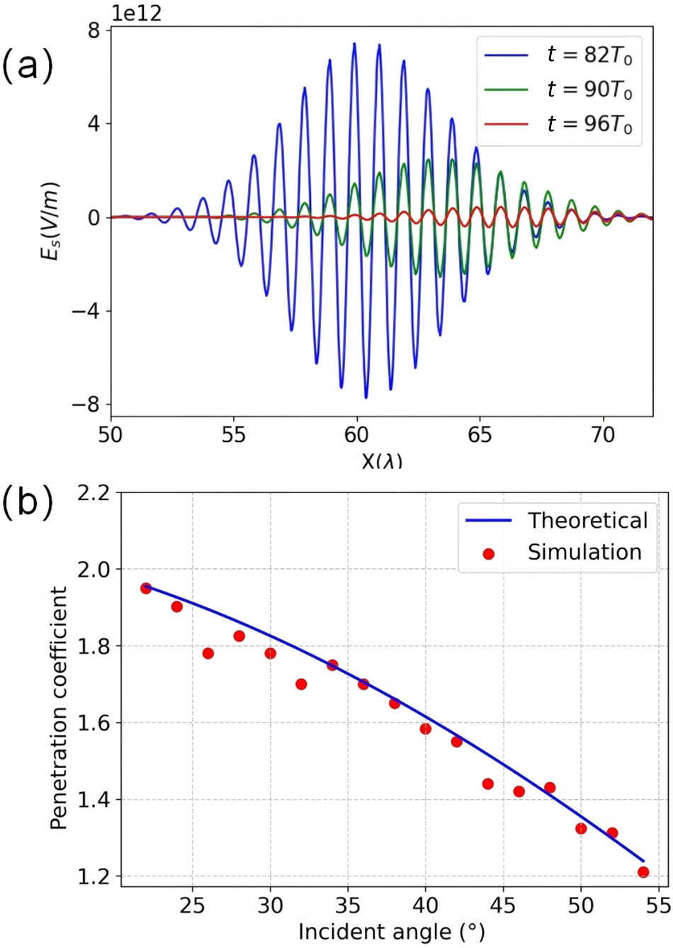
When the incident angle exceeds the critical angle for TIR, the refracted wave is converted into a surface wave. This surface wave then ultimately transforms into the reflected wave, and it is precisely this conversion sequence that gives rise to the change in the phase difference of the reflected wave. To visualize this dynamic process, Figure 3(a), derived from 2D PIC simulations, illustrates the s-component electric field of the surface wave ${E}_\mathrm{s}^{\mathrm{t}}$
at various instants. When
${E}_\mathrm{s}^{\mathrm{t}}$
at various instants. When $t=82{T}_0$
, where
$t=82{T}_0$
, where ${T}_0$
represents the characteristic period of the incident laser, the moment of interaction between the laser and the plasma surface occurs. At this juncture,
${T}_0$
represents the characteristic period of the incident laser, the moment of interaction between the laser and the plasma surface occurs. At this juncture, ${E}_\mathrm{s}^{\mathrm{t}}$
reaches its maximum value. As time progresses, it is evident that the amplitude of the surface wave gradually diminishes, and during this period, the surface wave undergoes a gradual transformation into the reflected wave, completing the TIR process.
${E}_\mathrm{s}^{\mathrm{t}}$
reaches its maximum value. As time progresses, it is evident that the amplitude of the surface wave gradually diminishes, and during this period, the surface wave undergoes a gradual transformation into the reflected wave, completing the TIR process.
(a) The s-polarized electric field of the surface wave ${E}_\mathrm{s}^{\mathrm{t}}$
at different moments. (b) The transmission coefficient of
${E}_\mathrm{s}^{\mathrm{t}}$
at different moments. (b) The transmission coefficient of ${E}_\mathrm{s}^{\mathrm{t}}$
at different incident angles.
${E}_\mathrm{s}^{\mathrm{t}}$
at different incident angles.
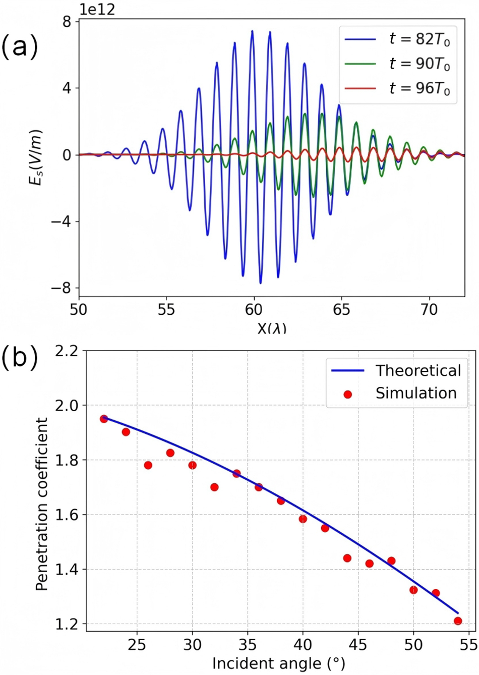
Figure 3(b) shows the transmission coefficients of ${E}_\mathrm{s}^{\mathrm{t}}$
under different incident angles. As the incident angle increases, the electric field amplitude of the surface wave gradually weakens, and this phenomenon is consistent with the following theoretical formula:
${E}_\mathrm{s}^{\mathrm{t}}$
under different incident angles. As the incident angle increases, the electric field amplitude of the surface wave gradually weakens, and this phenomenon is consistent with the following theoretical formula:
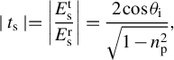 $$\begin{align}\mid {t}_\mathrm{s}\mid =\left|\frac{E_\mathrm{s}^\mathrm{t}}{E_\mathrm{s}^\mathrm{r}}\right|=\frac{2\cos {\theta}_{\mathrm{i}}}{\sqrt{1-{n}_{\mathrm{p}}^2}},\end{align}$$
where ${t}_\mathrm{s}$
is the transmission coefficient and
${t}_\mathrm{s}$
is the transmission coefficient and ${E}_\mathrm{s}^\mathrm{t}$
and
${E}_\mathrm{s}^\mathrm{t}$
and ${E}_\mathrm{s}^\mathrm{r}$
represent the electric fields of the surface wave (transmitted wave) and the reflected wave, respectively. This formula, grounded in the fundamental principles of electromagnetic wave propagation at the plasma–vacuum interface, provides a theoretical framework for predicting the behavior of surface waves. The close match between the simulation results and the theoretical formula, as shown in Figure 3(b), further validates the accuracy of our theoretical model.
${E}_\mathrm{s}^\mathrm{r}$
represent the electric fields of the surface wave (transmitted wave) and the reflected wave, respectively. This formula, grounded in the fundamental principles of electromagnetic wave propagation at the plasma–vacuum interface, provides a theoretical framework for predicting the behavior of surface waves. The close match between the simulation results and the theoretical formula, as shown in Figure 3(b), further validates the accuracy of our theoretical model.
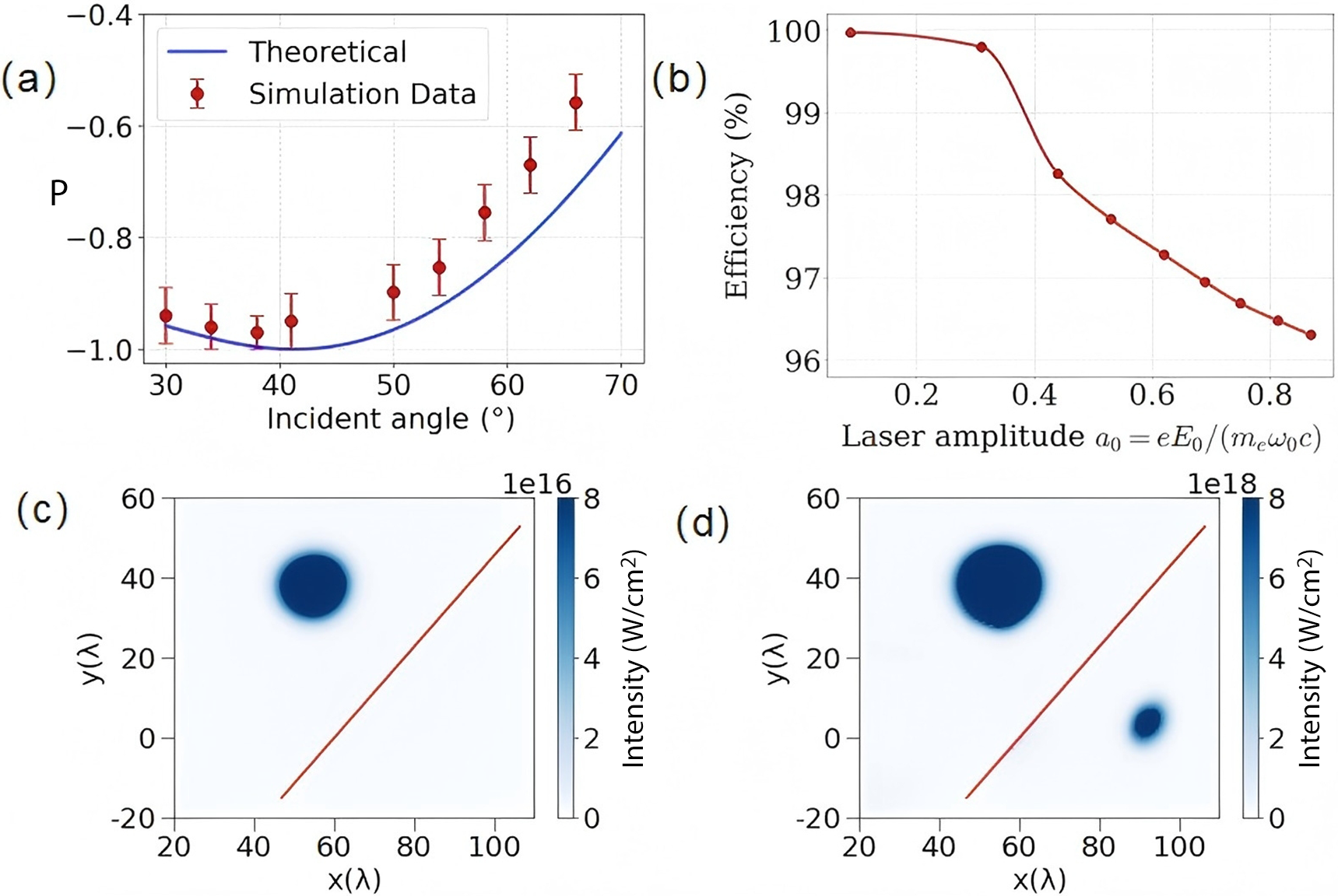
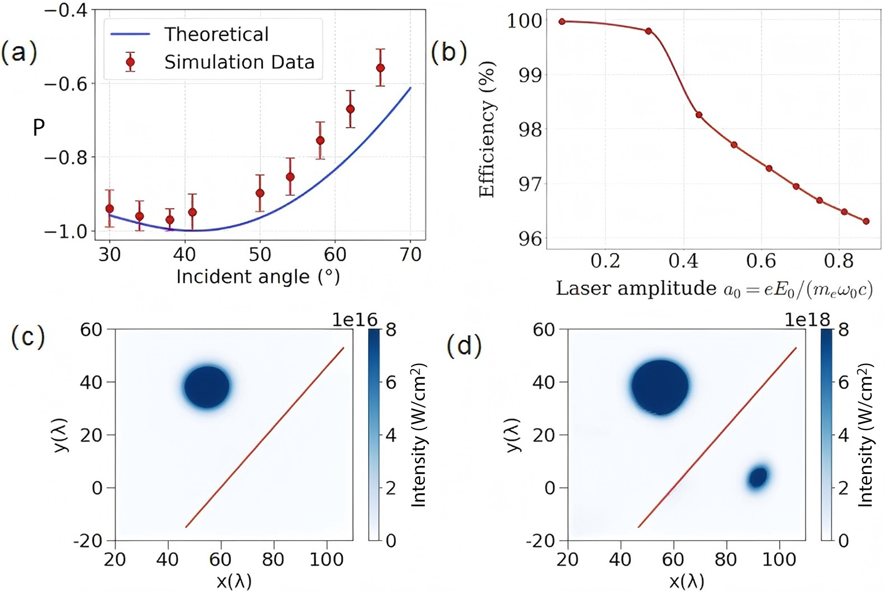
Next we demonstrate that this plasma-based polarization modulator is tunable and capable of achieving a controllable phase shift between two orthogonal field components. Specifically, in TIR process, the phase difference between p- and s-polarized components varies with the incident angle, as indicated in Equation (6), which endows this principle with continuous tunability. Figure 4(a) shows the simulation and theoretical results of the Stokes parameter of the reflected laser under different incident angles. It can be seen that the simulation results agree well with the theoretical results, and demonstrate the tunability of the polarization degree in the present scheme.
(a) The Stokes parameter P under different incident angles. (b) Reflection efficiencies for different normalized laser amplitudes ${a}_0$
. (c) The laser intensity distribution of the reflected wave when the normalized laser amplitude
${a}_0$
. (c) The laser intensity distribution of the reflected wave when the normalized laser amplitude ${a}_0=0.087$
. (d) The laser intensity distribution of the reflected wave when the normalized laser amplitude
${a}_0=0.087$
. (d) The laser intensity distribution of the reflected wave when the normalized laser amplitude ${a}_0=0.87$
. To display the distribution of the transmitted laser, the magnitude of the colorbar is reduced by two orders of magnitude.
${a}_0=0.87$
. To display the distribution of the transmitted laser, the magnitude of the colorbar is reduced by two orders of magnitude.
We further consider the influence of laser amplitude ${a}_0$
. The normalized amplitude
${a}_0$
. The normalized amplitude ${a}_0= eE/{m}_\mathrm{e}\omega c$
, as a core Lorentz invariant, holds the following physical significance: when
${a}_0= eE/{m}_\mathrm{e}\omega c$
, as a core Lorentz invariant, holds the following physical significance: when ${a}_0\ge 1$
, the laser intensity enters the fully relativistic regime. In the near-threshold region (
${a}_0\ge 1$
, the laser intensity enters the fully relativistic regime. In the near-threshold region ( $0.1<{a}_0<1$
), the plasma target structure can already be modified through the density perturbation mechanism (see Figure 5(d)). As shown in Figure 4(b), although the overall conversion efficiency gradually decreases with increasing
$0.1<{a}_0<1$
), the plasma target structure can already be modified through the density perturbation mechanism (see Figure 5(d)). As shown in Figure 4(b), although the overall conversion efficiency gradually decreases with increasing ${a}_0$
, it remains above
${a}_0$
, it remains above $95\%$
across the studied intensity range. Furthermore, we verified that even under specific extreme parameters with a wavelength of 10 nm and a laser intensity of
$95\%$
across the studied intensity range. Furthermore, we verified that even under specific extreme parameters with a wavelength of 10 nm and a laser intensity of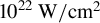 ${10}^{22}\ \mathrm{W}/{\mathrm{cm}}^2$
(the corresponding laser power is 1 TW), the reflection efficiency still reaches
${10}^{22}\ \mathrm{W}/{\mathrm{cm}}^2$
(the corresponding laser power is 1 TW), the reflection efficiency still reaches $96.37\%$
, confirming that TIR can be stably maintained within this high-efficiency regime. It is noted that for
$96.37\%$
, confirming that TIR can be stably maintained within this high-efficiency regime. It is noted that for ${a}_0=0.087$
(Figure 4(c)), no detectable light intensity is observed behind the target, confirming that the laser energy is predominantly retained via TIR. In contrast, when
${a}_0=0.087$
(Figure 4(c)), no detectable light intensity is observed behind the target, confirming that the laser energy is predominantly retained via TIR. In contrast, when ${a}_0=0.87$
(Figure 4(d)), a distinct transmitted signal emerges behind the target, demonstrating that a high-intensity laser can breach TIR constraints and penetrate the plasma target directly.
${a}_0=0.87$
(Figure 4(d)), a distinct transmitted signal emerges behind the target, demonstrating that a high-intensity laser can breach TIR constraints and penetrate the plasma target directly.
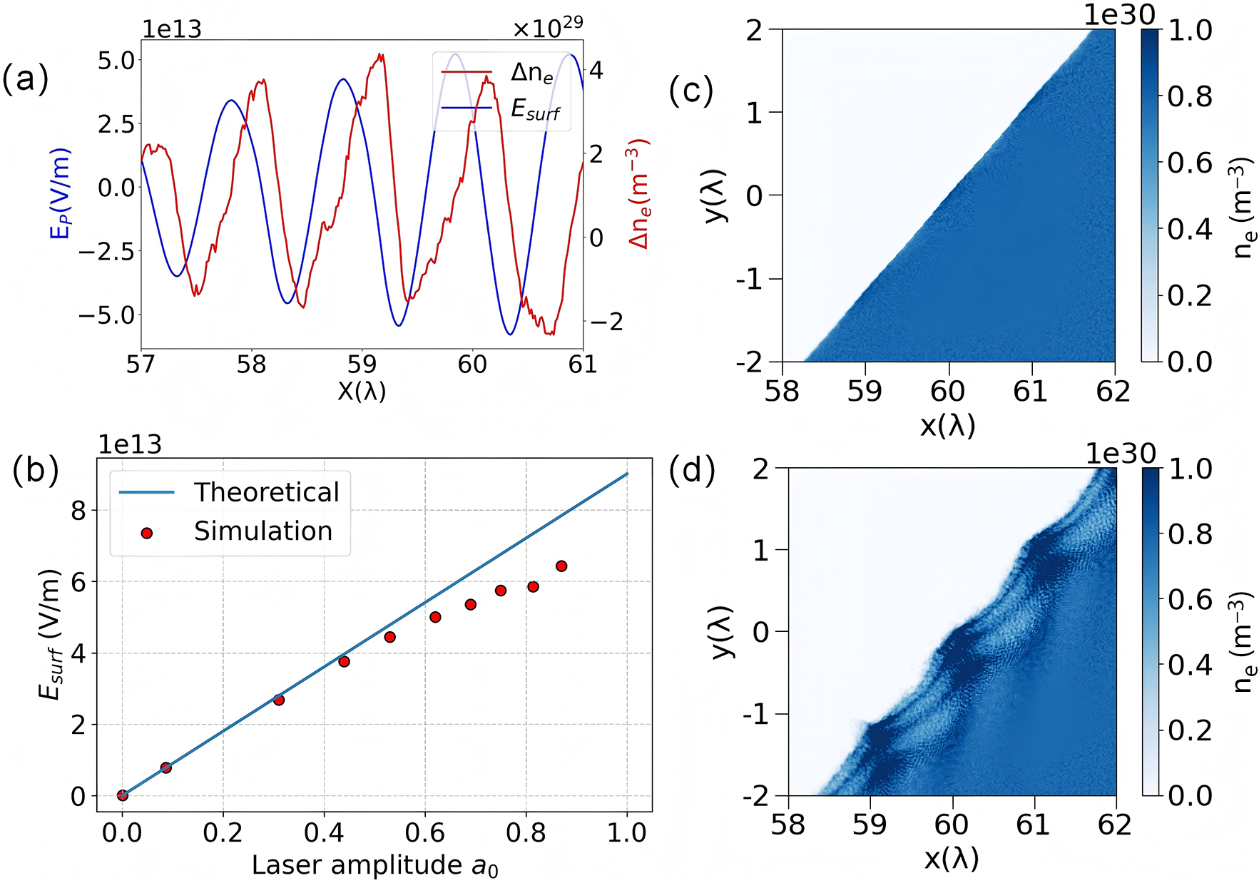
(a) Electron density and electric field variation at the interface for ${a}_0=0.87$
. (b) Electric field of surface wave versus
${a}_0=0.87$
. (b) Electric field of surface wave versus ${a}_0$
. (c) Electron density distribution for
${a}_0$
. (c) Electron density distribution for ${a}_0=0.087$
. (d) Electron density distribution for
${a}_0=0.087$
. (d) Electron density distribution for ${a}_0=0.87$
.
${a}_0=0.87$
.
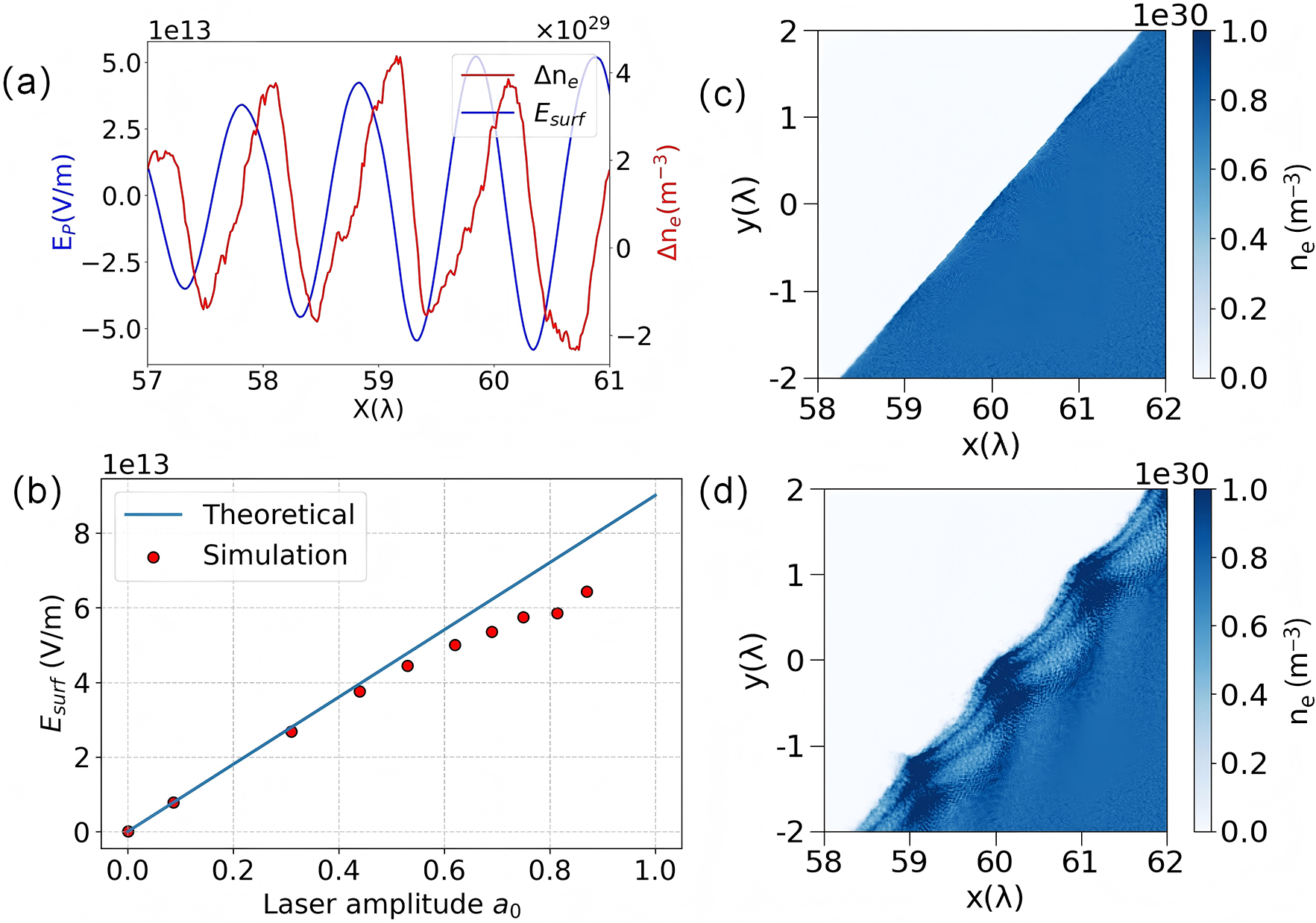
The physical origin of these transmission disparities lies in the dynamics of surface plasmon polaritons (SPPs). During TIR, surface waves propagate along the vacuum–plasma interface, inducing oscillating electric fields that generate surface charges. Collective oscillations of these charges form SPPs[ Reference Zhang, Zhang and Xu 39 ]. As the laser intensity increases, the electric field of the surface wave grows, amplifying electron oscillations and promoting the excitation of SPPs. Figure 5(a) demonstrates the synchronous evolution of plasma electron density perturbations (depicted by the red curve) and the electric field along the interface (represented by the blue curve), capturing the critical phase of laser–plasma interaction. The SPPs cause the electric field of the total-reflection-induced surface wave at the interface to be slightly lower than the theoretical value, as shown in Figure 5(b), where the amplitude of the electric field of the surface wave can be theoretically expressed as follows:
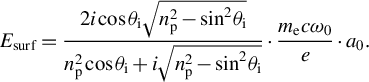 $$\begin{align}{E}_{\mathrm{surf}}=\frac{2i\cos {\theta}_{\mathrm{i}}\sqrt{n_{\mathrm{p}}^2-{\sin}^2{\theta}_{\mathrm{i}}}}{n_{\mathrm{p}}^2\cos {\theta}_{\mathrm{i}}+i\sqrt{n_{\mathrm{p}}^2-{\sin}^2{\theta}_{\mathrm{i}}}}\cdot \frac{m_\mathrm{e}c{\omega}_0}{e}\cdot {a}_0. \end{align}$$
Figures 5(c) and 5(d) show that plasma electron density responses vary significantly with ${a}_0$
. At low amplitudes (
${a}_0$
. At low amplitudes ( ${a}_0=0.087$
, Figure 5(c)), electron density perturbations remain minimal, and the interface remains smooth. At high amplitudes (
${a}_0=0.087$
, Figure 5(c)), electron density perturbations remain minimal, and the interface remains smooth. At high amplitudes ( ${a}_0=0.87$
, Figure 5(d)), intense SPP excitation induces the formation of protrusive structures at the plasma–vacuum interface, accompanied by drastic electron density redistribution. These structures alter the laser incidence angle and plasma density gradient, allowing partial laser transmission around TIR conditions. Quantitatively, increasing
${a}_0=0.87$
, Figure 5(d)), intense SPP excitation induces the formation of protrusive structures at the plasma–vacuum interface, accompanied by drastic electron density redistribution. These structures alter the laser incidence angle and plasma density gradient, allowing partial laser transmission around TIR conditions. Quantitatively, increasing ${a}_0$
from 0.087 to 0.87 decreases the reflection efficiency from 99.97% to 96.31%, directly validating the SPP-induced transmission enhancement. These findings deepen our understanding of laser–plasma interactions and offer insights for optimizing experiments where TIR efficiency matters.
${a}_0$
from 0.087 to 0.87 decreases the reflection efficiency from 99.97% to 96.31%, directly validating the SPP-induced transmission enhancement. These findings deepen our understanding of laser–plasma interactions and offer insights for optimizing experiments where TIR efficiency matters.
4 Discussion
The plasma-based polarization modulator exhibits stable performance and can operate within a wide range of laser parameters. In principle, as long as the normalized parameter $\frac{n_\mathrm{e}}{a_0{n}_\mathrm{c}}$
(the self-similar parameter in laser–plasma interactions) is fixed for different laser wavelengths, the present scheme can still be applicable[
Reference Pukhov
40
,
Reference Huang, Robinson, Zhou, Qiao, Liu, Ruan, He and Norreys
41
]. That is, the mechanism presented here is also applicable to the optical laser pulse. To verify this point, we conduct additional simulations with the laser wavelength of 800 nm, while keeping the values of
$\frac{n_\mathrm{e}}{a_0{n}_\mathrm{c}}$
(the self-similar parameter in laser–plasma interactions) is fixed for different laser wavelengths, the present scheme can still be applicable[
Reference Pukhov
40
,
Reference Huang, Robinson, Zhou, Qiao, Liu, Ruan, He and Norreys
41
]. That is, the mechanism presented here is also applicable to the optical laser pulse. To verify this point, we conduct additional simulations with the laser wavelength of 800 nm, while keeping the values of ${a}_0$
and
${a}_0$
and ${n}_\mathrm{e}=0.9{n}_\mathrm{c}$
the same as those for the case of the 36 nm wavelength laser.
${n}_\mathrm{e}=0.9{n}_\mathrm{c}$
the same as those for the case of the 36 nm wavelength laser.
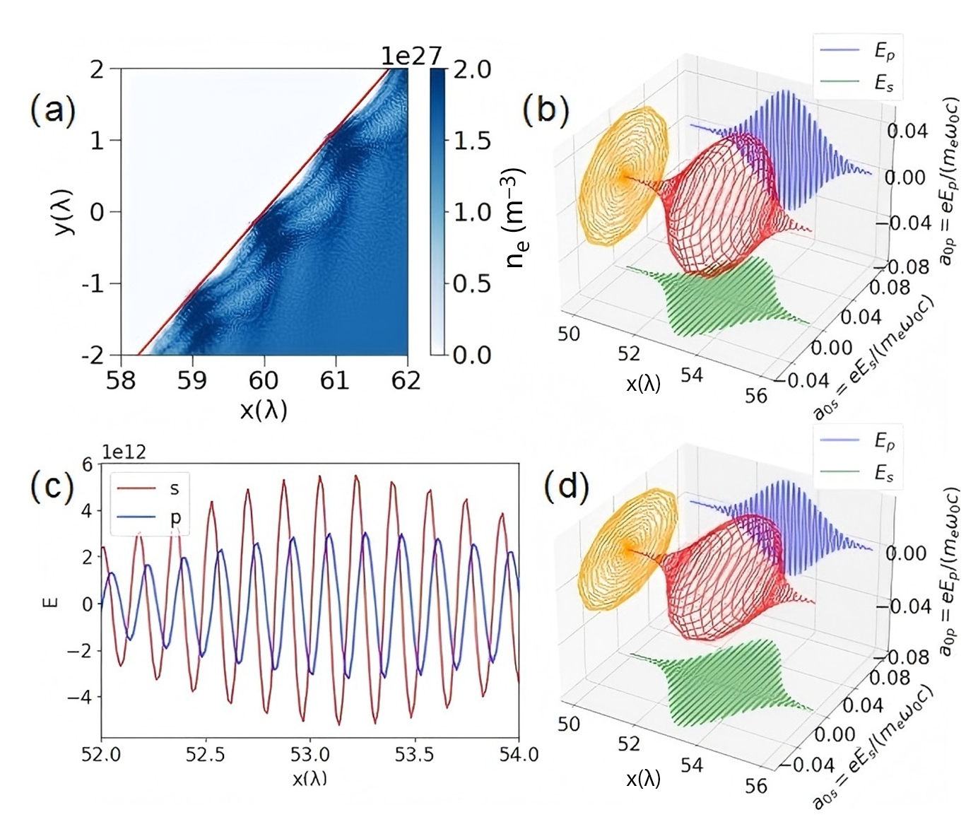
Figure 6(a) shows that for the case of ${a}_0=0.87$
, the resulting surface modulation on the plasma target is identical to that observed under the 36 nm wavelength condition, as shown in Figure 5(d). For the case of
${a}_0=0.87$
, the resulting surface modulation on the plasma target is identical to that observed under the 36 nm wavelength condition, as shown in Figure 5(d). For the case of ${a}_0=0.087$
, we investigate the polarization state of the reflected wave and find that the reflected wave remains CP, with the Stokes parameter P of 0.95 as shown in Figure 6(b). These results confirm that the present scheme can be well extended to lasers in the visible regime. While in these cases, the corresponding target is no longer a solid-density plasma but a near-critical-density plasma with density of
${a}_0=0.087$
, we investigate the polarization state of the reflected wave and find that the reflected wave remains CP, with the Stokes parameter P of 0.95 as shown in Figure 6(b). These results confirm that the present scheme can be well extended to lasers in the visible regime. While in these cases, the corresponding target is no longer a solid-density plasma but a near-critical-density plasma with density of $1.57\times {10}^{21}\;{\mathrm{cm}}^{-3}$
. Experimentally, carbon nanotube foam could be used to generate such near-critical-density plasma slab.
$1.57\times {10}^{21}\;{\mathrm{cm}}^{-3}$
. Experimentally, carbon nanotube foam could be used to generate such near-critical-density plasma slab.
(a) Electron density distribution under the conditions of ${a}_0=0.87$
and
${a}_0=0.87$
and $\lambda =800\;\mathrm{nm}$
. (b) Electric field intensity distribution along the central axis of the reflected laser when
$\lambda =800\;\mathrm{nm}$
. (b) Electric field intensity distribution along the central axis of the reflected laser when ${a}_0=0.087$
and
${a}_0=0.087$
and $\lambda =800\;\mathrm{nm}$
. (c) Electric field of the reflected laser along the central axis, where the incident laser is set to linear polarization with a
$\lambda =800\;\mathrm{nm}$
. (c) Electric field of the reflected laser along the central axis, where the incident laser is set to linear polarization with a $60{}^{\circ}$
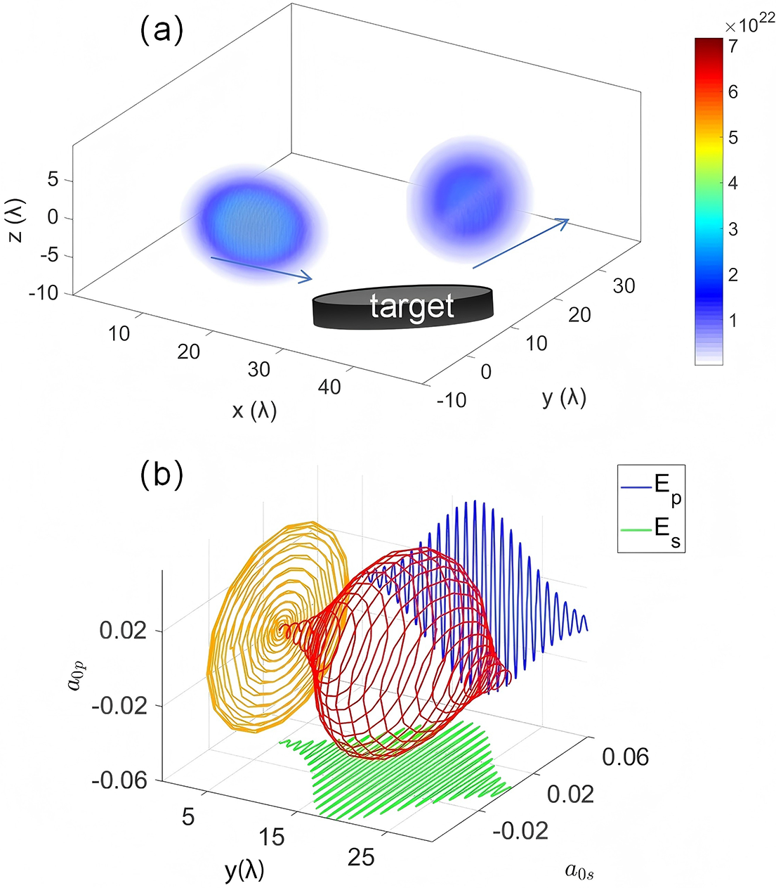
angle in the y–z plane. (d) Three-dimensional state distribution diagram derived from the same dataset as in (c).
$60{}^{\circ}$
angle in the y–z plane. (d) Three-dimensional state distribution diagram derived from the same dataset as in (c).
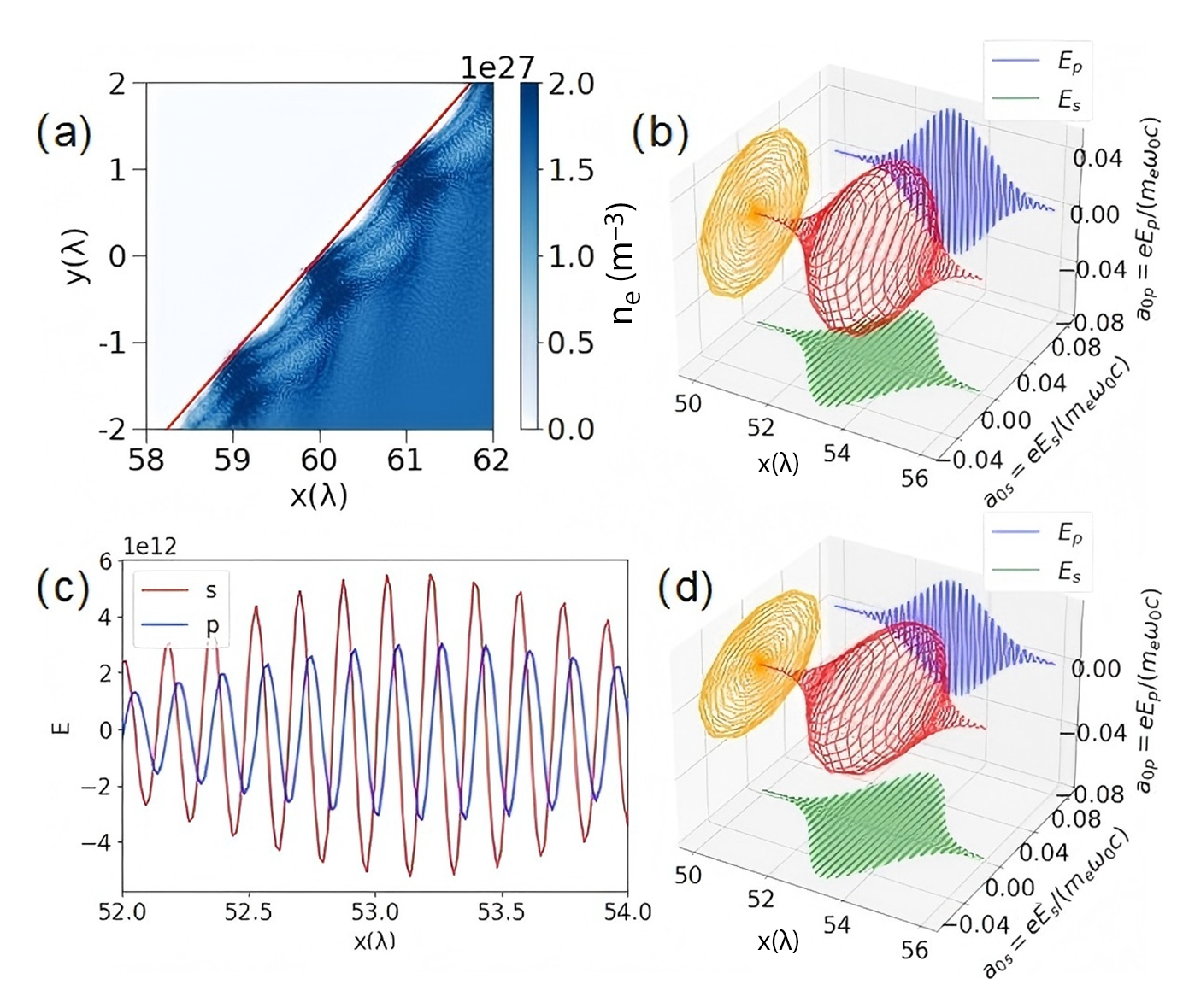
In the following, we shall further discuss some practical effects, including the polarization angle, the pre-plasma, the three-dimensional (3D) effect and the surface modulations. It is noted that in our simulations, the incident laser is actually set as $45{}^{\circ}$
linear polarization in the y–z plane to ensure the conversion from linear polarization to perfect circular polarization. To demonstrate the influence of this polarization angle, we conduct an additional simulation with an initial
$45{}^{\circ}$
linear polarization in the y–z plane to ensure the conversion from linear polarization to perfect circular polarization. To demonstrate the influence of this polarization angle, we conduct an additional simulation with an initial $60{}^{\circ}$
polarization angle relative to the y-axis in the y–z plane. As shown in Figures 6(c) and 6(d), the polarization state of the reflected light has changed. This is because the initial phases of the orthogonal polarization components of the incident light are equal, but their amplitudes are different. The TIR process only modifies the phase without altering the amplitude. Consequently, the phase difference of the reflected light still satisfies
$60{}^{\circ}$
polarization angle relative to the y-axis in the y–z plane. As shown in Figures 6(c) and 6(d), the polarization state of the reflected light has changed. This is because the initial phases of the orthogonal polarization components of the incident light are equal, but their amplitudes are different. The TIR process only modifies the phase without altering the amplitude. Consequently, the phase difference of the reflected light still satisfies $\pi /2$
, but the amplitudes remain unequal, resulting in elliptical polarization. Therefore, to achieve the conversion from linear polarization to perfect circular polarization, the incident laser must be set to
$\pi /2$
, but the amplitudes remain unequal, resulting in elliptical polarization. Therefore, to achieve the conversion from linear polarization to perfect circular polarization, the incident laser must be set to $45{}^{\circ}$
linear polarization in the y–z plane.
$45{}^{\circ}$
linear polarization in the y–z plane.
Here we discuss the effects of pre-plasma. During the interaction between the laser and the plasma device, the laser usually produces pre-pulses (arriving at the target surface before the main pulse), which induce the formation of a pre-plasma layer that alters the electron density distribution near the target surface[ Reference Phipps, Zhigilei, Polynkin, Baumert, Sarnet, Bulgakova, Bohn and Reif 42 ], thereby affecting TIR. Although the double-laser irradiation scheme[ Reference Beier, Allison, Efthimion, Flippo, Gao, Hansen, Hill, Hollinger, Logantha, Musthafa, Nedbailo, Senthilkumaran, Shepherd, Shlyaptsev, Song, Wang, Dollar, Rocca and Hussein 38 ] can lead to very homogeneous solid-density plasma, the existence of pre-plasma in front of the plasma surface is still inevitable. To simulate the impact of this process on polarization state conversion, an exponentially decaying pre-plasma was implemented ahead of the main plasma target, defined as follows:
 $$\begin{align}{n}_{\mathrm{e}}={n}_{\mathrm{e}0}\exp \left(-b\left(x-{x}_0\right)/{\lambda}_0\right),\end{align}$$
where ${n}_{\mathrm{e}0}$
denotes the density of the main plasma target,
${n}_{\mathrm{e}0}$
denotes the density of the main plasma target, ${\lambda}_0$
represents the wavelength of the incident laser and
${\lambda}_0$
represents the wavelength of the incident laser and $b$
governs the density decay rate (a smaller b corresponds to a larger-scale pre-plasma with a slower decay rate). Other parameters were kept unchanged during the simulation.
$b$
governs the density decay rate (a smaller b corresponds to a larger-scale pre-plasma with a slower decay rate). Other parameters were kept unchanged during the simulation.
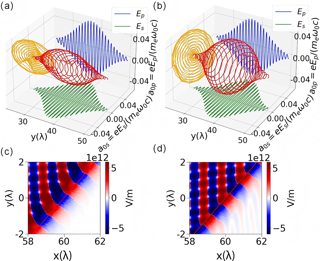
When $b=1$
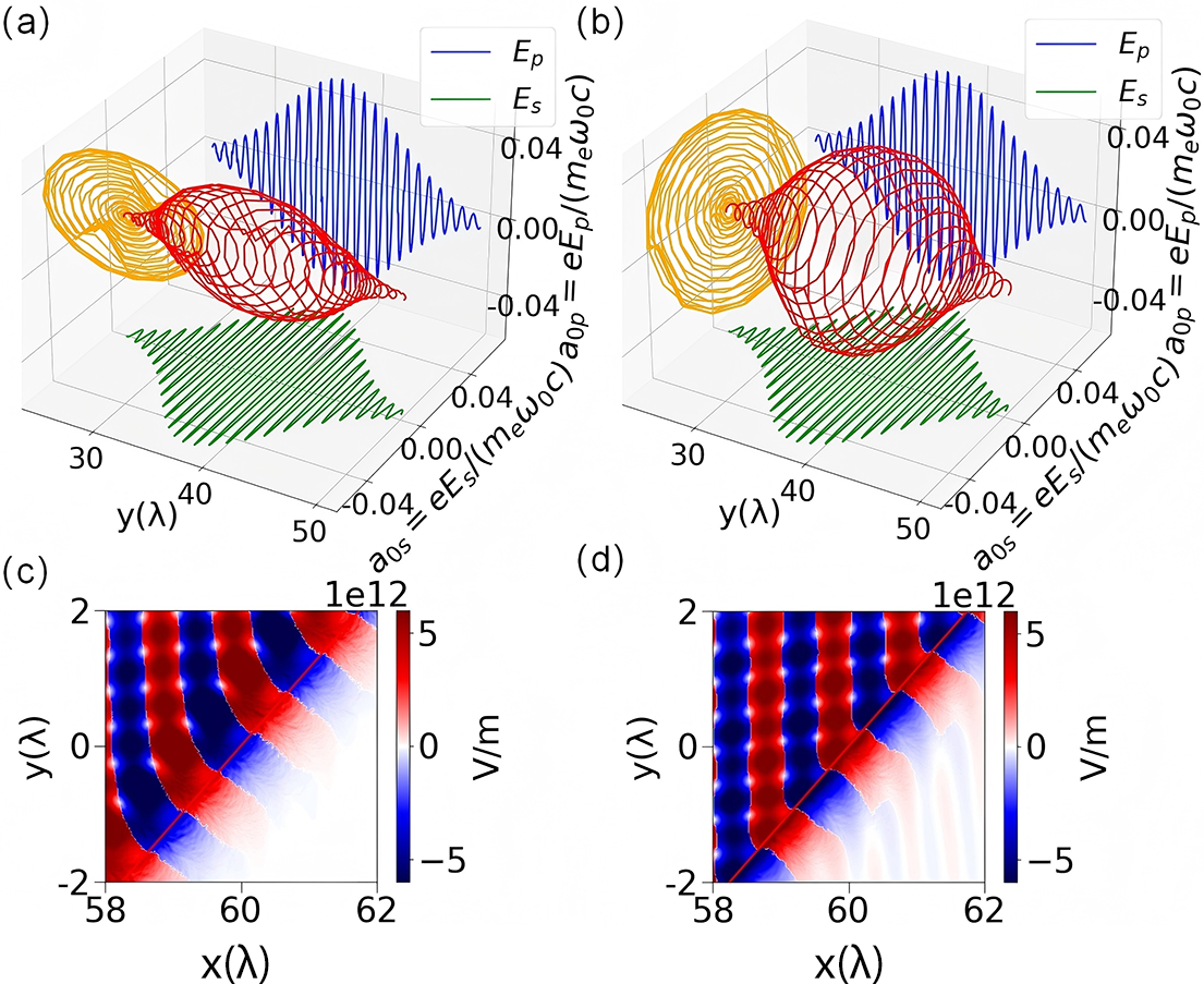
(corresponding to a relatively large-scale pre-plasma), as shown in Figure 7(a), the reflected laser exhibits elliptical polarization with Stokes parameter
$b=1$
(corresponding to a relatively large-scale pre-plasma), as shown in Figure 7(a), the reflected laser exhibits elliptical polarization with Stokes parameter $P=-0.6\pm 0.05$
. This deviation arises from two factors: (1) refraction within the pre-plasma modifies the effective angle of incidence; (2) partial reflection in the pre-plasma layer disrupts the TIR process. As depicted in Figure 7(c), the incident laser interacts with the pre-plasma before contacting the plasma target, leading to an increase in the angle of incidence. In contrast, when
$P=-0.6\pm 0.05$
. This deviation arises from two factors: (1) refraction within the pre-plasma modifies the effective angle of incidence; (2) partial reflection in the pre-plasma layer disrupts the TIR process. As depicted in Figure 7(c), the incident laser interacts with the pre-plasma before contacting the plasma target, leading to an increase in the angle of incidence. In contrast, when $b=5$
, the influence is significantly reduced due to the thinner pre-plasma layer. As shown in Figure 7(b), the reflected laser remains CP with Stokes parameter
$b=5$
, the influence is significantly reduced due to the thinner pre-plasma layer. As shown in Figure 7(b), the reflected laser remains CP with Stokes parameter $P=-0.94\pm 0.04$
. Figure 7(d) reveals that the angle of incidence of the laser remains almost unchanged in this case.
$P=-0.94\pm 0.04$
. Figure 7(d) reveals that the angle of incidence of the laser remains almost unchanged in this case.
(a) Electric field of the reflected laser along the central axis at $b=1$
. (b) Electric field of the reflected laser along the central axis at
$b=1$
. (b) Electric field of the reflected laser along the central axis at $b=5$
. (c) Electric field distribution at the interaction moment when
$b=5$
. (c) Electric field distribution at the interaction moment when $b=1$
. (d) Electric field distribution at the interaction moment when
$b=1$
. (d) Electric field distribution at the interaction moment when $b=5$
.
$b=5$
.
To improve the accuracy of the simulation, we further supplemented the study with a 3D geometric configuration. The simulation domain extends from $0$
to
$0$
to $50{\lambda}_0$
in the
$50{\lambda}_0$
in the $x$
-direction, from
$x$
-direction, from $-10{\lambda}_0$
to
$-10{\lambda}_0$
to $40{\lambda}_0$
in the
$40{\lambda}_0$
in the $y$
-direction and from
$y$
-direction and from $-10{\lambda}_0$
to
$-10{\lambda}_0$
to $10{\lambda}_0$
in the
$10{\lambda}_0$
in the $z$
-direction. The simulation employs a 3D grid configuration with
$z$
-direction. The simulation employs a 3D grid configuration with $800\times 800\times 320$
grid points. The grid spacing is
$800\times 800\times 320$
grid points. The grid spacing is ${\lambda}_0/16$
, which is equivalent to
${\lambda}_0/16$
, which is equivalent to $16$
points per wavelength, and there are
$16$
points per wavelength, and there are $10$
particles per grid point. Parameters such as laser intensity, incident angle and plasma density remain unchanged, and the LP X-ray laser pulse has an incident angle of
$10$
particles per grid point. Parameters such as laser intensity, incident angle and plasma density remain unchanged, and the LP X-ray laser pulse has an incident angle of $\theta =41.3{}^{\circ}$
.
$\theta =41.3{}^{\circ}$
.
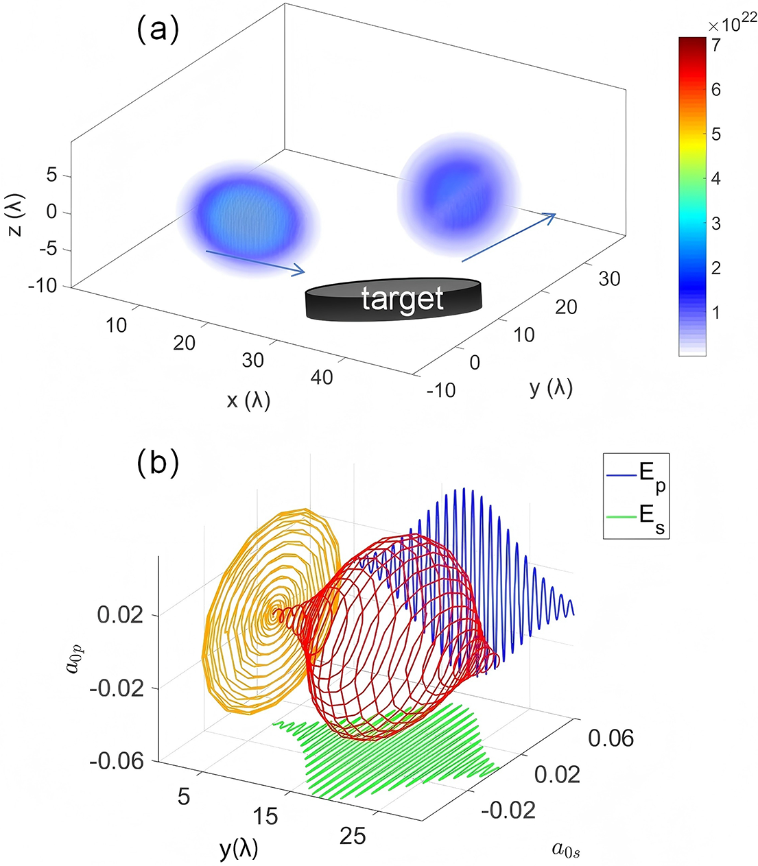
As shown in Figure 8(a), the intensity distribution of the laser indicates that TIR has occurred, with almost no energy loss. Figure 8(b) shows the electric field amplitude of the reflected laser along the central axis at $z=0$
, confirming that its polarization state has been converted to left-handed circular polarization, with a Stokes parameter of
$z=0$
, confirming that its polarization state has been converted to left-handed circular polarization, with a Stokes parameter of $P=-0.96\pm 0.04$
. Therefore, this 3D simulation can also achieve efficient conversion from linear polarization to circular polarization.
$P=-0.96\pm 0.04$
. Therefore, this 3D simulation can also achieve efficient conversion from linear polarization to circular polarization.
The 3D simulation results of (a) the spatial intensity distribution of the reflected laser and (b) the electric field intensity along the central axis of the reflected laser at $z=0$
.
$z=0$
.
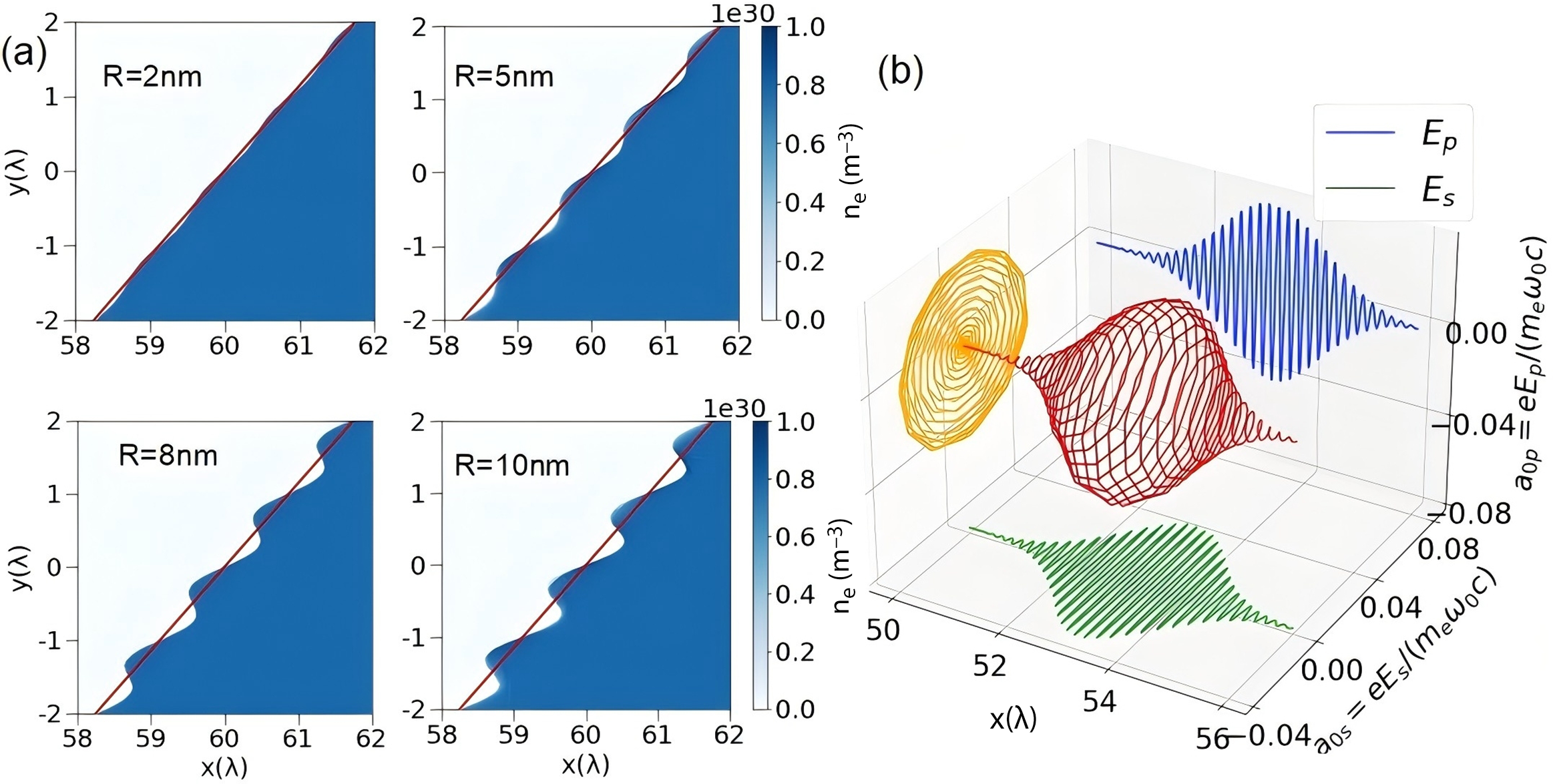
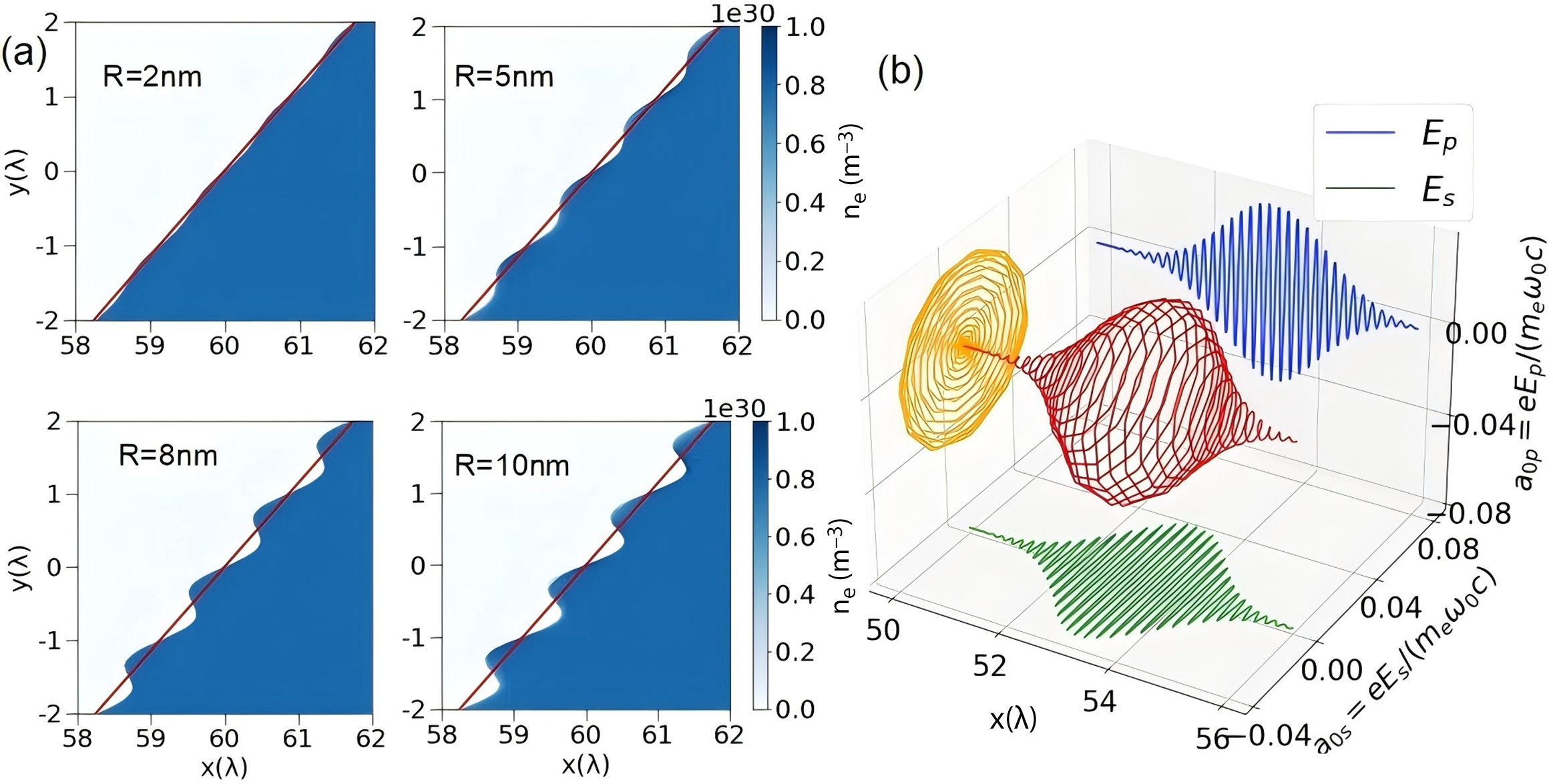
In the practical case, surface modulation may also occur at the target surface on the X-ray wavelength scale. To describe this effect, we add a modulation function $R\times \sin \left(2\times \pi \times y/\lambda \right)$
on the plasma surface to form a textured target, where
$R\times \sin \left(2\times \pi \times y/\lambda \right)$
on the plasma surface to form a textured target, where $R$
is set to 2, 5, 8 and 10 nm, respectively, as illustrated in Figure 9(a). In Figure 9(b), we present the s-polarized and p-polarized electric fields of the reflected laser when
$R$
is set to 2, 5, 8 and 10 nm, respectively, as illustrated in Figure 9(a). In Figure 9(b), we present the s-polarized and p-polarized electric fields of the reflected laser when $R=10\;\mathrm{nm}$
, and it is indicated that the polarization state remains circular. It is found that the influence of this modulated surface on the polarization state is negligible. However, as
$R=10\;\mathrm{nm}$
, and it is indicated that the polarization state remains circular. It is found that the influence of this modulated surface on the polarization state is negligible. However, as $R$
increases, the total reflection efficiency decreases sequentially to
$R$
increases, the total reflection efficiency decreases sequentially to $97\%$
,
$97\%$
, $82\%$
,
$82\%$
, $67\%$
,
$67\%$
, $57\%$
for
$57\%$
for $R=2$
,
$R=2$
, $5$
,
$5$
, $8$
and
$8$
and $10\;\mathrm{nm}$
, respectively. This is attributed to the textured nature of the total reflection interface: some incident angles deviate from the designed value, and part of the laser undergoes direct transmission, leading to reduced reflectivity. It is noted that state-of-the-art nanofabrication techniques can already achieve a fabrication precision of
$10\;\mathrm{nm}$
, respectively. This is attributed to the textured nature of the total reflection interface: some incident angles deviate from the designed value, and part of the laser undergoes direct transmission, leading to reduced reflectivity. It is noted that state-of-the-art nanofabrication techniques can already achieve a fabrication precision of $2\;\mathrm{nm}$
[
Reference Bostedt, Boutet, Fritz, Huang, Lee, Lemke, Robert, Schlotter, Turner and Williams
43
,
Reference Gour, Beer, Paul, Alberucci, Steinert, Szeghalmi, Siefke, Peschel, Nolte and Zeitner
44
]. Therefore, the experimental realization of such an efficient polarization conversion regime could be feasible in the near-future.
$2\;\mathrm{nm}$
[
Reference Bostedt, Boutet, Fritz, Huang, Lee, Lemke, Robert, Schlotter, Turner and Williams
43
,
Reference Gour, Beer, Paul, Alberucci, Steinert, Szeghalmi, Siefke, Peschel, Nolte and Zeitner
44
]. Therefore, the experimental realization of such an efficient polarization conversion regime could be feasible in the near-future.
(a) Plasma density distribution of concave structures with a surface roughness of 2–10 nm. (b) Electric field intensity distribution along the central axis of the reflected laser (R = 10 nm).
5 Concluding remarks
We present a novel approach to achieve polarization conversion of high-power, high-intensity X-ray lasers via oblique reflection from a solid-density plasma target. Leveraging the refractive index of solid-density plasma (which is less than unity in the X-ray regime), TIR occurs when the X-ray laser is incident at angles exceeding the critical angle. This configuration enables compact and efficient polarization conversion. Particle-in-cell simulations confirm this plasma-based polarization modulator, demonstrating not only its high damage threshold and efficiency (up to 95% conversion efficiency) but also its tunability through adjustment of the incident angle. This combination of compactness, robustness, efficiency and adjustability positions the scheme as a versatile tool with potential applications in high-energy-density physics, advanced X-ray laser systems and related research frontiers.
Acknowledgements
This work is supported by the National Natural Science Foundation of China (Grant Nos. 12175154, 12475248, 12235014 and 12205201), the National Key R&D Program of China (Grant No. 2024YFA1613400), the Shenzhen Science and Technology Program (Grant No. RCYX20221008092851073), the Guangdong Province Key Construction Discipline Scientific Research Capacity Improvement Project (Grant No. 2021ZDJS107), the Guangdong Basic and Applied Basic Research Foundation (Grants Nos. 2025A1515010791 and 2025A1515012853) and the Natural Science Foundation of Top Talent of SZTU (Grants Nos. GDRC202310 and GDRC202423).














 Open access

