


1 Introduction
In recent decades, rapid advances in high-intensity laser (HIL) technology have created unparalleled opportunities to investigate a wide range of physical disciplines, most notably plasma-based nuclear and particle physics[ Reference Yoon, Kim, Choi, Sung, Lee, Lee and Nam1– Reference Yang, Wang, Wilkins and Garcia Ruiz4]. For example, by directing HIL beams onto materials, researchers can recreate extreme conditions comparable to those found in astrophysical phenomena, nuclear fusion reactions and high-energy particle collisions[ Reference Ditmire, Bless, Dyer, Edens, Grigsby, Hays, Madison, Maltsev, Colvin, Edwards, Lee, Patel, Price, Remington, Sheppherd, Wootton, Zweiback, Liang and Kielty5– Reference Hu, Bishel, Chin, Nilson, Karasiev, Golovkin, Gu, Hansen, Mihaylov, Shaffer, Zhang and Walton9]. Such experiments allow scientists to study matter under extreme temperatures and pressures, probe plasma dynamics and investigate related fundamental physical processes. Furthermore, HILs have found applications in disciplines such as energy production[ Reference Tassart10, Reference Glenzer, MacGowan, Michel, Meezan, Suter, Dixit, Kline, Kyrala, Bradley, Callahan, Dewald, Divol, Dzenitis, Edwards, Hamza, Haynam, Hinkel, Kalantar, Kilkenny, Landen, Lindl, LePape, Moody, Nikroo, Parham, Schneider, Town, Wegner, Widmann, Whitman, Young, Van Wonterghem, Atherton and Moses11], materials science[ Reference Betti and Hurricane12, Reference Shugaev, Wu, Armbruster, Naghilou, Brouwer, Ivanov, Derrien, Bulgakova, Kautek, Rethfeld and Zhigilei13] and astrophysical research[ Reference Remington, Drake and Ryutov14, Reference Kuramitsu, Chu, Hau, Chen, Liu, Hsieh, Sakawa, Hideaki and Wang15].
In particular, nuclear isomers induced by HILs have received wide attention in recent years[
Reference Wang, Zhou, Liu and Wang16–
Reference Yang, Spohr, Cernaianu, Doria, Ghenuche and Hornỳ22]. Thanks to the extreme power density of HILs, the efficient production of short-lived nuclear isomers within extremely short time frames has become feasible. For example, the production of the isomeric state of ${}^{83}\mathrm{Kr}$
with a peak efficiency of
${}^{83}\mathrm{Kr}$
with a peak efficiency of $2.34\times {10}^{15}$
particles per second has been achieved on a tabletop hundred-TW laser system, which is of great significance for research on nuclear transition mechanisms and nuclear
$2.34\times {10}^{15}$
particles per second has been achieved on a tabletop hundred-TW laser system, which is of great significance for research on nuclear transition mechanisms and nuclear $\gamma$
-ray lasers[
Reference Feng, Wang, Fu, Chen, Tan, Li, Wang, Li, Zhang, Ma and Zhang17]. Moreover, the study of the laser-pumping process of
$\gamma$
-ray lasers[
Reference Feng, Wang, Fu, Chen, Tan, Li, Wang, Li, Zhang, Ma and Zhang17]. Moreover, the study of the laser-pumping process of ${}^{229\mathrm{m}}\mathrm{Th}$
not only promotes the field of nuclear clocks but also provides a method to tune between two different nuclear-excitation mechanisms[
Reference Qi, Zhang and Wang18]. In addition, the
${}^{229\mathrm{m}}\mathrm{Th}$
not only promotes the field of nuclear clocks but also provides a method to tune between two different nuclear-excitation mechanisms[
Reference Qi, Zhang and Wang18]. In addition, the ${}^{115}\mathrm{In}{\left(\gamma, n\right)}^{114\mathrm{m}2}\mathrm{In}$
reaction has been investigated using ultra-intense gamma-rays driven by high-power lasers, providing a new approach for measuring the cross-section data of short-lived isomers[
Reference Wu, Lan, Liu, Lu, Zhang, Lv, Wu, Zhang, Xia, He, Cai, Ma, Xia, Wang, Wang, Yang, Xu, Geng, Lin, Ma, Zhao, Wang, Liu, He, Yu, Guo, Zhang, Xu, Wang, Ma, Mourou and Yan19].
${}^{115}\mathrm{In}{\left(\gamma, n\right)}^{114\mathrm{m}2}\mathrm{In}$
reaction has been investigated using ultra-intense gamma-rays driven by high-power lasers, providing a new approach for measuring the cross-section data of short-lived isomers[
Reference Wu, Lan, Liu, Lu, Zhang, Lv, Wu, Zhang, Xia, He, Cai, Ma, Xia, Wang, Wang, Yang, Xu, Geng, Lin, Ma, Zhao, Wang, Liu, He, Yu, Guo, Zhang, Xu, Wang, Ma, Mourou and Yan19].
However, conducting precise experimental measurements is faced with significant challenges, especially for those nuclear isomers with ultra-short lifetimes, primarily due to the powerful electromagnetic pulses (EMPs) generated in HIL experiments[ Reference Hanbing, Cui, Jiang, Wu and Zhiqian23– Reference He, Wang, Deng, Feng, Xia, Hu, Zhu, Xie, Yuan, Zhang, Lu, Yang, Cheng, Li, Yan, Fang, Li, Zhou, Li, Chen, Lin and Yan25]. These EMPs, with peak intensities reaching up to MV/m and a broad frequency domain extending from several MHz to THz, are produced during the interaction between the laser and the target and persist for several microseconds[ Reference He, Wang, Deng, Feng, Xia, Hu, Zhu, Xie, Yuan, Zhang, Lu, Yang, Cheng, Li, Yan, Fang, Li, Zhou, Li, Chen, Lin and Yan25, Reference Niu, Kang, Xu, Xie, Teng, Liu, Sun and Li26]. For semiconductor detectors, EMP fields can exceed the applied bias voltages, leading to signal distortion or permanent damage[ Reference Yee, Orvis and Martin27]. Similar issues affect photomultiplier tubes (PMTs), where EMPs disrupt the electric fields between dynodes, rendering them ineffective[ Reference Shurenkov and Pershenkov28]. As a result, even if scintillators remain functional, the overall detection system fails due to malfunctions of PMTs and electronics. In particular, EMPs with high-power microwave components can also disrupt amplifiers, analog-to-digital converters and computers[ Reference Consoli, Tikhonchuk, Bardon, Bradford, Carroll, Cikhardt, Cipriani, Clarke, Cowan, Danson, De Angelis, De Marco, Dubois, Etchessahar, Laso Garcia, Hillier, Honsa, Jiang, Kmetik, Krása, Li, Lubrano, McKenna, Metzkes-Ng, Poyé, Prencipe, Rączka, Smith, Vrana, Woolsey, Zemaityte, Zhang, Zhang, Zielbauer and Neely29, Reference Cao, Xie, Chang, Li, Yue, Yu, Wang, Tang, Li, Wang and Lu30].
To overcome these challenges, some detection methods have been developed, such as CR-39 track detectors[ Reference Jeong, Singh, Scullion, Ahmed, Hadjisolomou, Jeon, Yun, Kakolee, Borghesi and Ter-Avetisyan31, Reference Zhang, Wang, Ma, Liu, Cao, Fan, Zhang and Fang32], imaging plates (IPs)[ Reference Li, Qin, Zhang, Li, Fan, Wang, Xu, Wang, Yu, Xu, Liu, Wang, Wang, Zhang, Liu, Bai, Gan, Zhang, Wang, Fan, Sun, Tang, Yao, Liang, Leng, Shen, Ji, Li and Xu33, Reference Shou, Wang, Lee, Rhee, Lee, Yoon, Sung, Lee, Pan, Kong, Mei, Liu, Xu, Deng, Zhou, Tajima, Choi, Yan, Nam and Ma34], radiochromic film (RCF)[ Reference Nürnberg, Schollmeier, Brambrink, Blažević, Carroll, Flippo, Gautier, Geißel, Harres, Hegelich, Lundh, Markey, McKenna, Neely, Schreiber and Roth35, Reference Feng, Tiedje, Gagnon and Fedosejevs36] and activation techniques using materials such as copper[ Reference Cooper, Ruiz, Leeper, Chandler, Hahn, Nelson, Torres, Smelser, McWatters, Bleuel, Yeamans, Knittel, Casey, Frenje, Johnson, Petrasso and Styron37, Reference Yang38]. However, these techniques rely on off-line processing, which may require breaking the vacuum environment of the target chamber and may take tens of minutes or even hours to handle. Moreover, quasi-real-time measurements based on gated detectors or self-activation methods still face challenges in directly detecting signals with durations shorter than the microsecond range following laser–target interactions[ Reference Hu, Ma, Zhao, Zhang, Fang, Wei, Fu and Ma39– Reference Xu, Ning, Qin, Teng, Feng, Tang, Chen, Fukao, Mihara and Oishi41]. This not only impedes the applications of high-repetition-rate lasers but also obstructs the research of ultra-fast physical processes on the microsecond to nanosecond time scale.
In this paper, an optical-fiber-coupled scintillation detector (FSD) is proposed that features excellent resistance to EMPs, a fast response time on the nanosecond scale and single-particle detection capability at high event rates. This technology is applied to detect the first excited state ${}^{83\mathrm{m}1}$
Kr pumped by an HIL, which has a lifetime as short as
${}^{83\mathrm{m}1}$
Kr pumped by an HIL, which has a lifetime as short as ${T}_{1/2}$
=156.94 ns. The result demonstrates the potential of this technique for future applications in PW-level high-repetition-rate laser experiments to explore more ultra-short and ultra-fast physical processes.
${T}_{1/2}$
=156.94 ns. The result demonstrates the potential of this technique for future applications in PW-level high-repetition-rate laser experiments to explore more ultra-short and ultra-fast physical processes.
2 Detector design
For use in high-repetition-rate HIL experiments, the detector must meet several key requirements: robustness against EMPs, high detection efficiency and a short response time.
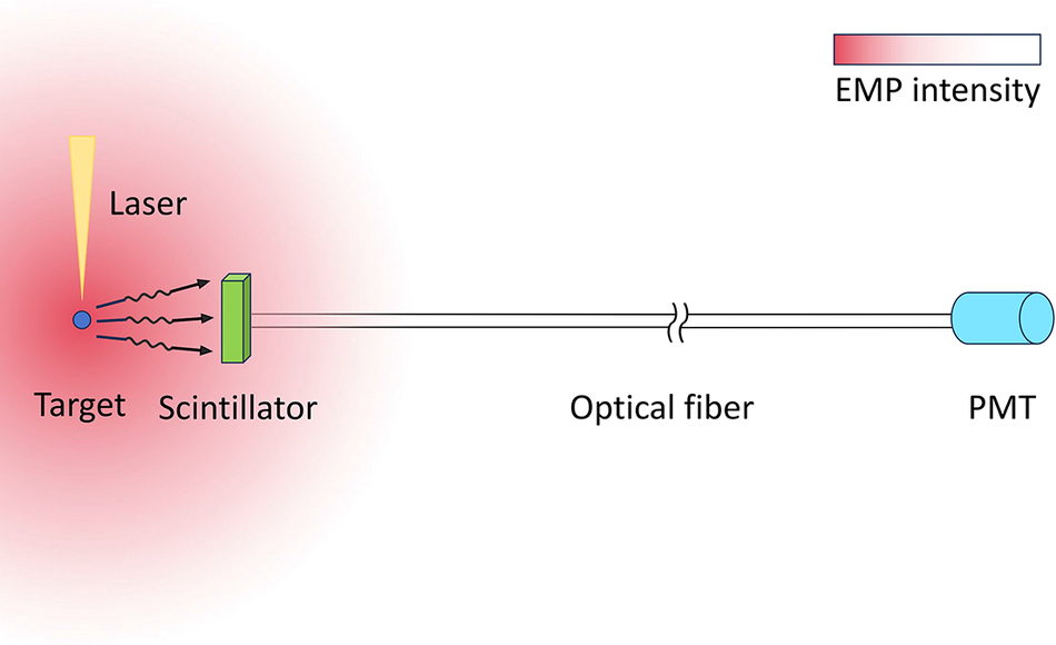
As shown in Figure 1, in a typical HIL experiment, the intensity distribution of EMPs in space is inversely proportional to the square of the distance from the target. Considering that the scintillator crystal is insensitive to EMPs, it can be placed as a probe close to the target to increase the detection solid angle. Meanwhile, PMTs and other electronics systems are placed at a relatively long distance to mitigate the interference of EMPs. The two parts, the scintillator and the PMTs, are connected by a long optical fiber to transmit the fluorescence produced in the scintillator.
Schematic diagram of the working principle of the optical-fiber-coupled scintillation detector.

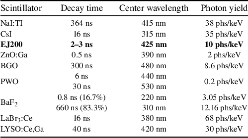
To record fast physical processes, a scintillator with a fast time response should be chosen to match the processes under study, preferably within tens of nanoseconds or even a few nanoseconds. On the other hand, since the fluorescence generated in the scintillator needs to be transmitted through a long optical fiber and undergo two surface couplings before being received by the PMTs, optical attenuation becomes a significant issue. This requires the scintillator to have a high photon yield when excited. The typical performance parameters of commonly used scintillators are provided in Table 1. Here, we selected the plastic scintillator EJ200, which strikes a good balance between response time and light yield, as well as its robustness against EMPs. In addition, it can maintain stable performance even when exposed to air for a long time, making it easy for further processing.
Performance parameters of some typical scintillation crystals[ Reference Lecoq42, Reference Bell43].

To ensure that the PMTs can ultimately receive a sufficient number of photons, two types of transmission optical fibers were used in this study. They are the multimode quartz optical fiber FP1500URT from Thorlab Corporation and the plastic optical fiber SK80 from Mitsubishi Corporation. As can be seen in Table 2, both fibers have a very high numerical aperture, and their optical attenuation in the fluorescence band of EJ200 is acceptable within a length of 100 m. Despite efforts to ensure the PMT receives as many fluorescent photons as possible, due to the relative energy error $\frac{\sigma E}{E}\simeq \frac{1}{\sqrt{N}}$
, a reduction in the number of fluorescent photons
$\frac{\sigma E}{E}\simeq \frac{1}{\sqrt{N}}$
, a reduction in the number of fluorescent photons $N$
significantly degrades the already poor energy resolution of the scintillation detector. Consequently, this detection approach will mainly function as a signal counter to acquire the temporal information of radiation particles.
$N$
significantly degrades the already poor energy resolution of the scintillation detector. Consequently, this detection approach will mainly function as a signal counter to acquire the temporal information of radiation particles.

In this study, the normally-off photosensor module H11526-110-NF from Hamamatsu Corporation was adopted. The combination of the built-in metal package PMT and gate circuit makes this module compact yet still provides excellent characteristics: 100 ns minimum gate width, 180 ns gate delay and 10 kHz repetition rate. Gating the PMT to be off-line at the onset of laser–target interaction shields it from intense X-rays generated during this process. These X-rays, lasting tens of nanoseconds, produce abundant fluorescence in the scintillator probe, imposing a heavy burden on the normally operating PMT[
Reference Cannavò, Torrisi, Ceccio, Cutroneo, Calcagno, Sciuto and Mazzillo46]. This module also contains a high-voltage power supply so that PMT gain can be varied by simply adjusting the control voltage. Notably, it has a cathode radiant sensitivity as high as 80 mA/W in the wavelength range of 300–500 nm and a PMT gain of up to ${10}^7$
, which is crucial for acquiring significantly attenuated fluorescence signals[
47].
${10}^7$
, which is crucial for acquiring significantly attenuated fluorescence signals[
47].
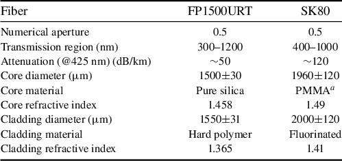
The three main modules after assembly are shown in Figures 2(a)–2(c). They are connected to each other in pairs through helical fiber-optic connectors. To enhance the collection efficiency of scintillator fluorescence, a coupling scheme from the scintillator to the fiber is designed, a cross-sectional diagram of which is shown in Figure 2(d). We embedded a scintillator with dimensions of $30 \text{ mm }\times 10\text{ mm }\times 1.5 \text{ mm}$
in a metal base. Deeper below it, a bare wavelength-shifting fiber with a diameter of 1.5 mm was buried for light collection[
48]. The surface of the metal base was coated with a reflective material. The gap between the scintillator and the optical fiber was filled with highly transparent optical glue.
$30 \text{ mm }\times 10\text{ mm }\times 1.5 \text{ mm}$
in a metal base. Deeper below it, a bare wavelength-shifting fiber with a diameter of 1.5 mm was buried for light collection[
48]. The surface of the metal base was coated with a reflective material. The gap between the scintillator and the optical fiber was filled with highly transparent optical glue.
Detector components and their structures used in the experiment: (a) the scintillator probe; (b) the transmission optical fiber; (c) the photomultiplier tube. These modules are interconnected by a helical fiber-optic connector to facilitate convenient assembly and disassembly. (d) Cross-sectional view of the scintillator probe where the grey part is the metal base, the blue part is the scintillation crystal and the green cylindrical part is the wavelength-shifting optical fiber.

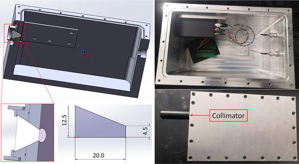
For comparison, another aluminum-box shielded scintillation detector (ASD) was designed, enabling the PMT to operate inside the target chamber, thereby reducing the coupling and transmission loss of scintillation light. As shown in Figure 3, the scintillation crystal is coupled to the internal PMT through a frustum-shaped quartz glass that penetrates the wall of a sealed aluminum box and is coated on the side surface with reflective material. The diameters of the two ends of the quartz glass are 25 and 9 mm respectively, with a height of 20 mm. During the actual experimental detection process, a 10 cm collimator was installed at the front end of the scintillator to avoid interference from laser scattering and ambient light.
Design diagram (left) and physical assembly diagram (right) of the aluminum-box shielded scintillation detector (the indicated size data are in millimeters).

3 Experimental setup
This experiment was conducted at the PW beamline of the chirped pulse amplification (CPA) laser system at the Shanghai Superintense Ultrafast Laser Facility (SULF)[ Reference Zhang, Wu, Hu, Yang, Gui, Ji, Liu, Wang, Liu, Lu, Xu, Leng, Li and Xu49]. The facility normally operates at a wavelength of 800 nm, with a pulse duration of 30 fs, energy up to 30 J, a focal radius of 30 μm and a repetition rate of 0.1 Hz.
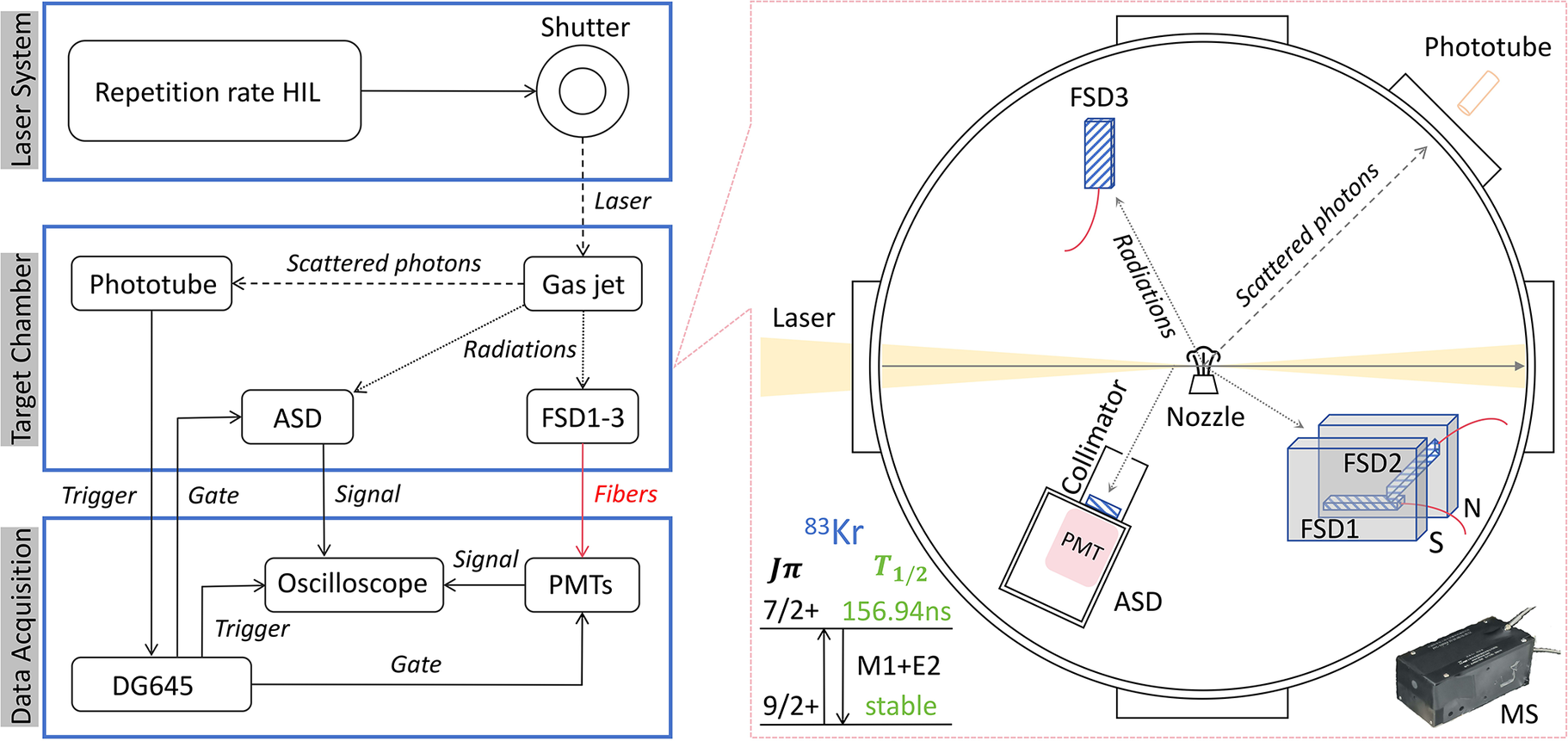
Figure 4 illustrates the workflow and setup in this experiment. The optical shutter is there to control the repetition rate at which the HIL enters the experimental area. A phototube is set up at the window of the target chamber to detect the moment when the laser arrives and further trigger the remote digital pulse delay generator (DG645 was used in this experiment). In response, the DG645 equipment sends delayed pulses to the oscilloscope and PMTs, providing triggering and gating signals, respectively, to activate the data acquisition and detector system. The feature that the scintillator crystal is coupled to the PMT via a long optical fiber was clearly demonstrated, using spatial separation to avoid the destructive interference from strong EMPs on the electronics of the detector system.
Experimental workflow and setup. The entire experiment consists of three major modules: the laser system, the interaction target chamber and the data acquisition module. The laser system can provide a maximum repetition rate of 0.1 Hz for the experiment. In the target chamber, one set of ASDs and three sets of FSDs are deployed. The FSDs are coupled to the remote PMTs through optical fibers. In the data acquisition module, the DG645 equipment controls each detector and the oscilloscope based on the trigger signal from the phototube in the target chamber. The deployment locations and schemes of the detectors in the target chamber are presented in more detail on the right-hand side.

A more detailed display of the deployment positions and schemes of the detectors in the target chamber can be seen on the right-hand side of Figure 4, where three sets of FSDs and one set of ASDs were employed. FSD1 and FSD2 were placed in a magnetic spectrometer (MS) at an angle of 37 degrees to the forward direction of the laser, where the magnetic field strength was 0.5 T, to deflect high-energy electrons. The radiation to be measured would enter through a circular window with a diameter of 1.5 cm covered with 20 μm aluminum foil at the front end of the MS. FSD1 was placed horizontally while FSD2 was placed at an angle of 40 degrees to the horizontal plane, with the geometric centers of the two being 20.5 and 26 cm away from the nozzle center, respectively. FSD3 was positioned vertically to the horizontal plane, 46.5 cm away from the center of the nozzle, forming an angle of 105 degrees with the forward direction of the laser. The ASD was placed 30 cm from the nozzle center, forming a 120-degree angle with the right-hand side of the laser forward direction in the horizontal plane. Its collimation direction deviated 2 cm from the center of the nozzle to reduce the impact of $t=0$
X-rays from the target. The scintillator parts of both FSD3 and ASD are wrapped with 20 μm aluminum foil to avoid interference from charged particles and ambient visible light.
$t=0$
X-rays from the target. The scintillator parts of both FSD3 and ASD are wrapped with 20 μm aluminum foil to avoid interference from charged particles and ambient visible light.
During the experiment, the laser’s optical axis passed 1 mm above a supersonic nozzle. The natural Kr gas with 11.5% ${}^{83}$
Kr isotope used in the experiment was ejected into the vacuum chamber from the nozzle with adjustable back pressure at the moment of laser irradiation. The high-pressure Kr gas undergoes adiabatic expansion during ejection, rapidly cooling and condensing into nanoparticles or clusters[
Reference Boldarev, Faenov, Fukuda, Jinno, Pikuz, Kando, Kondo and Kodama50,
Reference Zhang, Chen, Yuan, Yan, Wang, Liu, Shen, Faenov, Pikuz, Skobelev, Gasilov, Boldarev, Mao, Li, Dong, Lu, Ma, Wang, Sheng and Zhang51]. When the laser irradiates these Kr clusters, they become ionized, and before the clusters disintegrate, the electrons are rapidly heated to a mean energy of several keV due to various collective effects and nonlinear processes[
Reference Ditmire, Tisch, Springate, Mason, Hay, Smith, Marangos and Hutchinson52]. Previous studies have shown that, due to nonlinear resonance mechanisms in the laser–cluster interaction, energetic electrons with energies up to the order of mega-electron-volts can reverse direction more than 20 times as the laser field oscillates[
Reference Feng, Wang, Fu, Chen, Tan, Li, Wang, Li, Zhang, Ma and Zhang17]. This oscillation allows the energetic electrons to move back and forth, repeatedly colliding with relatively stationary
${}^{83}$
Kr isotope used in the experiment was ejected into the vacuum chamber from the nozzle with adjustable back pressure at the moment of laser irradiation. The high-pressure Kr gas undergoes adiabatic expansion during ejection, rapidly cooling and condensing into nanoparticles or clusters[
Reference Boldarev, Faenov, Fukuda, Jinno, Pikuz, Kando, Kondo and Kodama50,
Reference Zhang, Chen, Yuan, Yan, Wang, Liu, Shen, Faenov, Pikuz, Skobelev, Gasilov, Boldarev, Mao, Li, Dong, Lu, Ma, Wang, Sheng and Zhang51]. When the laser irradiates these Kr clusters, they become ionized, and before the clusters disintegrate, the electrons are rapidly heated to a mean energy of several keV due to various collective effects and nonlinear processes[
Reference Ditmire, Tisch, Springate, Mason, Hay, Smith, Marangos and Hutchinson52]. Previous studies have shown that, due to nonlinear resonance mechanisms in the laser–cluster interaction, energetic electrons with energies up to the order of mega-electron-volts can reverse direction more than 20 times as the laser field oscillates[
Reference Feng, Wang, Fu, Chen, Tan, Li, Wang, Li, Zhang, Ma and Zhang17]. This oscillation allows the energetic electrons to move back and forth, repeatedly colliding with relatively stationary ${}^{83}$
Kr ions, efficiently producing the isomers
${}^{83}$
Kr ions, efficiently producing the isomers ${}^{83\mathrm{m}1}$
Kr (
${}^{83\mathrm{m}1}$
Kr ( $J\pi =7/2+$
, T
$J\pi =7/2+$
, T ${}_{1/2}$
= 156.94 ns) and
${}_{1/2}$
= 156.94 ns) and ${}^{83\mathrm{m}2}$
Kr (
${}^{83\mathrm{m}2}$
Kr ( $J\pi =1/2-$
, T
$J\pi =1/2-$
, T ${}_{1/2}$
= 1.83 h) through Coulomb excitation. Therefore, the de-excitation radiation with characteristic half-life can be recorded by the deployed detectors. The
${}_{1/2}$
= 1.83 h) through Coulomb excitation. Therefore, the de-excitation radiation with characteristic half-life can be recorded by the deployed detectors. The ${}^{83\mathrm{m}2}$
Kr was detected through off-line measurements by collecting reaction gases. The objective of this experiment is to achieve on-line detection of the shorter-lived
${}^{83\mathrm{m}2}$
Kr was detected through off-line measurements by collecting reaction gases. The objective of this experiment is to achieve on-line detection of the shorter-lived ${}^{83\mathrm{m}1}$
Kr via our FSD.
${}^{83\mathrm{m}1}$
Kr via our FSD.
4 Results and discussion
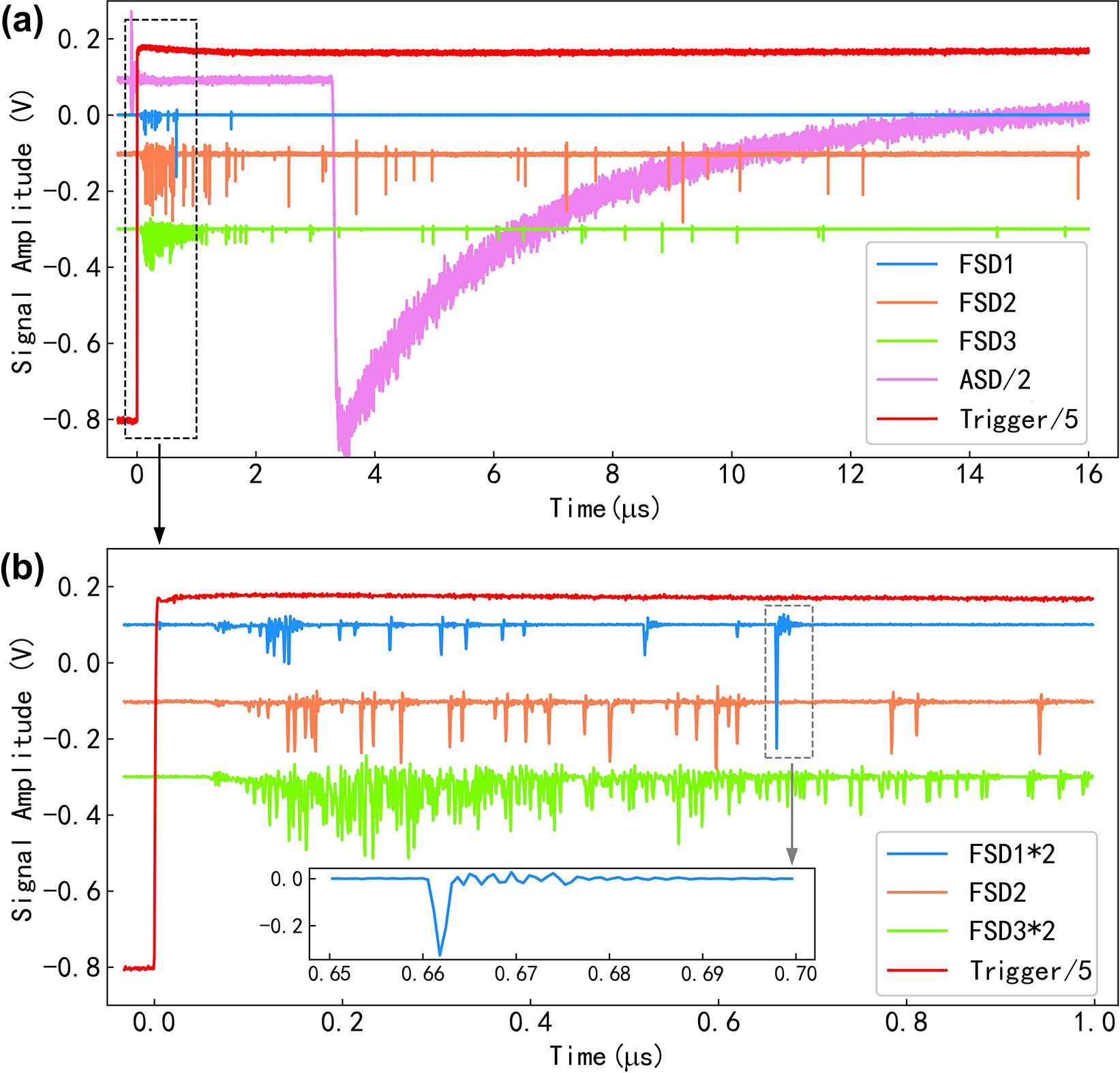
In this experiment, a total of 47 shots were carried out under the conditions of a jet back pressure of 6 MPa and a laser energy of 2 J. For a typical experimental shot, the signal response received by the oscilloscope is shown in Figure 5. For better visual presentation, we made necessary adjustments to the signal amplitude from different oscilloscope channels. Among them, the gating opening signals of SFD1–SFD3 are synchronized with the oscilloscope trigger, while the gating opening signal of the ASD is applied with a 3 μs delay.
Typical responses of each detector when the laser energy is 2 J and the back pressure of the Kr jet is 6 MPa.

4.1 The EMP resistance
As shown in Figure 5, the EMP resistance capability is evident. It can be seen from Figure 5(a) that although the ASD is provided with a gating protection as long as 3 μs, its electronic components, placed in the target chamber, have already oscillated due to the influence of the EMP at the moment of laser irradiation (near time zero of the oscilloscope). After the gate is opened, its response deviates seriously from the normal working state and does not fully recover even after more than 10 μs. The zoomed-in response of the FSDs within 1 μs after a laser shot, marked by a black dashed box in Figure 5(a), is shown separately in Figure 5(b). It can be seen that after receiving the gating signal, all three FSDs are on their normal operational bases already. After approximately 180 ns, they have all fully resumed operation and correctly recorded events. Obviously, it is necessary to adopt a PMT with a faster gating response, which will further improve the detector’s capability for earlier time detection. The grey dashed box of Figure 5(b) is the typical signal response of the FSD to a single particle, which is further enlarged and shown in the inset. It can be seen that, owing to the extremely short luminescence decay time of EJ200, the FSD has a response time of less than 5 ns, which endows it with a strong detection capability for ultra-fast signals at high event rates.
4.2 Suppression of X-ray background
In addition to EMPs, X-rays induced by the laser constitute a significant background, particularly at $t=0$
. Without proper suppression, the X-rays can cause the scintillator to saturate, potentially blinding the PMT.
$t=0$
. Without proper suppression, the X-rays can cause the scintillator to saturate, potentially blinding the PMT.
To evaluate the background and then ensure that the observed signals mainly originate from the de-excitation process of ${}^{83\mathrm{m}}$
Kr, we performed a set of control experiments where the laser irradiated N
${}^{83\mathrm{m}}$
Kr, we performed a set of control experiments where the laser irradiated N ${}_2$
jets. Figure 6 shows a comparison with Kr gas and pure N
${}_2$
jets. Figure 6 shows a comparison with Kr gas and pure N ${}_2$
gas targets, with the laser parameters and gas pressure remaining the same. The average counting rate per shot, with unit of counts per 30 ns per shot, is plotted as a function of time
${}_2$
gas targets, with the laser parameters and gas pressure remaining the same. The average counting rate per shot, with unit of counts per 30 ns per shot, is plotted as a function of time $t$
. In Figure 6(b), there is a noticeable spike in the count rate curve, which is marked by a dashed line at time
$t$
. In Figure 6(b), there is a noticeable spike in the count rate curve, which is marked by a dashed line at time $t=400$
ns. This is caused by the intense X-rays at
$t=400$
ns. This is caused by the intense X-rays at $t=0$
when the laser hits the target, which induces a large number of fluorescent photons in the scintillator. When they first reach the photocathode of the PMT, the PMT is not yet operational because it takes 180 ns for the gate to take effect.
$t=0$
when the laser hits the target, which induces a large number of fluorescent photons in the scintillator. When they first reach the photocathode of the PMT, the PMT is not yet operational because it takes 180 ns for the gate to take effect.
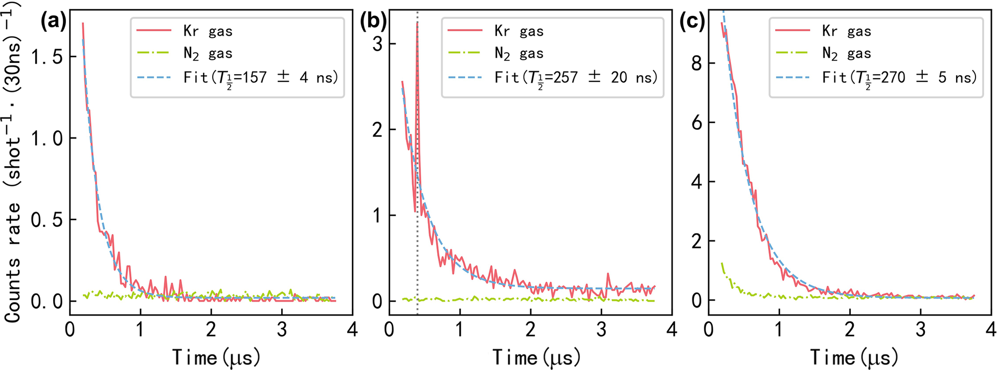
Normalized single-shot count rate, where (a)–(c) correspond to FSD1–FSD3, respectively. The red solid line and the green dash-dot line represent the experimental data from Kr gas and N ${}_2$
gas respectively, while the blue dashed line is the half-life fitting result of the Kr gas data.
${}_2$
gas respectively, while the blue dashed line is the half-life fitting result of the Kr gas data.

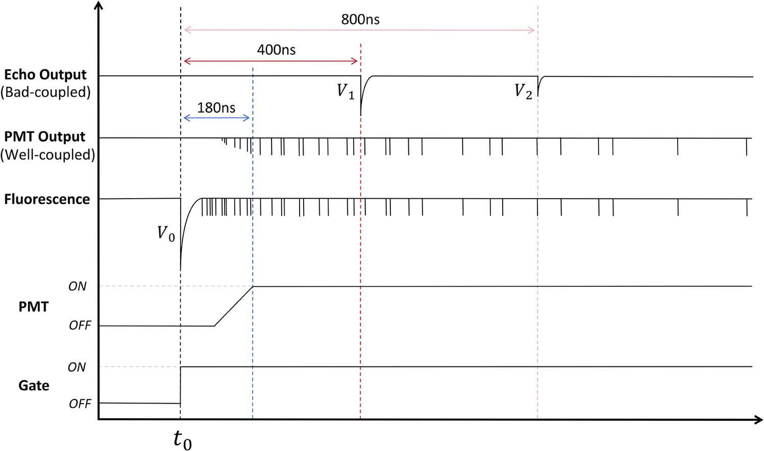
Because of the relatively worse coupling between the fiber and the PMT, some photons are reflected by the PMT window surface, and then travel back to the other end of the optical fiber (the scintillator side). At the scintillator side, the photons are reflected back again to the PMT side, and then received by the PMT, thereby generating the echo signals located at $t\simeq 400$
ns. Since light propagates 31% slower in a silica glass fiber than in vacuum[
Reference Poletti, Wheeler, Petrovich, Baddela, Fokoua, Hayes, Gray, Li, Slavík and Richardson53], the 400 ns corresponds to the time taken for a round trip in the 40-m-long silica fiber used in this experiment. Figure 7 presents a schematic diagram of the temporal response of the PMT to scintillation fluorescence. This indicates that improper coupling may lead the PMT to superpose an echo output of the scintillation fluorescence, which originates from the
$t\simeq 400$
ns. Since light propagates 31% slower in a silica glass fiber than in vacuum[
Reference Poletti, Wheeler, Petrovich, Baddela, Fokoua, Hayes, Gray, Li, Slavík and Richardson53], the 400 ns corresponds to the time taken for a round trip in the 40-m-long silica fiber used in this experiment. Figure 7 presents a schematic diagram of the temporal response of the PMT to scintillation fluorescence. This indicates that improper coupling may lead the PMT to superpose an echo output of the scintillation fluorescence, which originates from the $t=0$
moment of the laser–target interaction, onto the normal output.
$t=0$
moment of the laser–target interaction, onto the normal output.
Schematic diagram of FSD gating and signal response. The PMT requires 180 ns to revert to the normal operating state after receiving the gate-open signal[
47]. This time interval can precisely filter out the excessive fluorescence generated in the scintillator by the high-flux X-rays at $t=0$
of laser–target interaction. When the coupling at the fiber connection is poor, this fluorescence will be reflected back and forth between the two ends of the fiber while gradually attenuating.
$t=0$
of laser–target interaction. When the coupling at the fiber connection is poor, this fluorescence will be reflected back and forth between the two ends of the fiber while gradually attenuating.

With the reflection of fluorescence assumed as a linear process, there exists the relationship $\frac{V_0}{V_1}=\frac{V_1}{V_2}$
, where
$\frac{V_0}{V_1}=\frac{V_1}{V_2}$
, where ${V}_0$
is the original signals caused by the X-ray if being recorded by the PMT (but in fact it is gated out),
${V}_0$
is the original signals caused by the X-ray if being recorded by the PMT (but in fact it is gated out), ${V}_1$
is the first echo signals recorded by the PMT located at
${V}_1$
is the first echo signals recorded by the PMT located at $t\simeq$
400 ns and
$t\simeq$
400 ns and ${V}_2$
is the second echo signals located at
${V}_2$
is the second echo signals located at $t\simeq$
800 ns.
$t\simeq$
800 ns.
As shown in Figure 6(b), there is a peak at ${t}_1\simeq 400$
ns. By selecting data points within a small range around
${t}_1\simeq 400$
ns. By selecting data points within a small range around ${t}_1$
and performing a least-squares fit with the expression
${t}_1$
and performing a least-squares fit with the expression $C={V}_1\exp \left[-{\left(t-{t}_1\right)}^2/\left(2{\sigma}_1^2\right)\right]+{a}_1t+{b}_1$
, where
$C={V}_1\exp \left[-{\left(t-{t}_1\right)}^2/\left(2{\sigma}_1^2\right)\right]+{a}_1t+{b}_1$
, where ${V}_1$
,
${V}_1$
, ${t}_1$
,
${t}_1$
, ${a}_1$
and
${a}_1$
and ${b}_1$
are free parameters, one can obtain the peak value
${b}_1$
are free parameters, one can obtain the peak value ${V}_1=\left(2.0\pm 0.2\right)$
count
${V}_1=\left(2.0\pm 0.2\right)$
count $\cdot$
shot
$\cdot$
shot ${}^{-1}\cdot$
(30 ns)
${}^{-1}\cdot$
(30 ns) ${}^{-1}$
. Since the count rate is very low at
${}^{-1}$
. Since the count rate is very low at ${t}_2=2{t}_1\simeq 800$
ns, it can be assumed that the background follows a Poisson distribution. Therefore, the upper confidence limit of
${t}_2=2{t}_1\simeq 800$
ns, it can be assumed that the background follows a Poisson distribution. Therefore, the upper confidence limit of ${V}_2$
can be obtained from the equation
${V}_2$
can be obtained from the equation ${\sum}_{k=0}^{N-n\Delta {tV}_2}\frac{e^{-\widehat{B}}{\widehat{B}}^k}{k!}\ge 1-\alpha$
[
Reference Wasserman54], where
${\sum}_{k=0}^{N-n\Delta {tV}_2}\frac{e^{-\widehat{B}}{\widehat{B}}^k}{k!}\ge 1-\alpha$
[
Reference Wasserman54], where $N$
is the total count during a time bin
$N$
is the total count during a time bin $\Delta t=30$
ns from all experimental shots,
$\Delta t=30$
ns from all experimental shots, $n=47$
is the number of experimental shots,
$n=47$
is the number of experimental shots, $\widehat{B}$
is the background count predicted by an exponential fit and the significance level
$\widehat{B}$
is the background count predicted by an exponential fit and the significance level $\alpha =0.05$
. As a result, the possible peak value at
$\alpha =0.05$
. As a result, the possible peak value at ${t}_2$
is estimated to be
${t}_2$
is estimated to be ${V}_2\le$
0.064 count
${V}_2\le$
0.064 count $\cdot$
shot
$\cdot$
shot ${}^{-1}\cdot$
(30 ns)
${}^{-1}\cdot$
(30 ns) ${}^{-1}$
under a 95% confidence level (CL). Therefore, the lower limit of the count rate corresponds to
${}^{-1}$
under a 95% confidence level (CL). Therefore, the lower limit of the count rate corresponds to ${V}_0\ge 63$
count
${V}_0\ge 63$
count $\cdot$
shot
$\cdot$
shot ${}^{-1}\cdot$
(30 ns)−1 with 95% CL. In the absence of gating and filtering, such a strong signal may saturate the PMT, or even cause permanent damage. The other two sub-figures in Figure 6 indicate that, as long as the coupling end-faces of the optical fiber are properly processed, the gating can effectively isolate the interference of
${}^{-1}\cdot$
(30 ns)−1 with 95% CL. In the absence of gating and filtering, such a strong signal may saturate the PMT, or even cause permanent damage. The other two sub-figures in Figure 6 indicate that, as long as the coupling end-faces of the optical fiber are properly processed, the gating can effectively isolate the interference of $t=0$
X-rays.
$t=0$
X-rays.
4.3 Half-life of ${}^{83\mathrm{m}1}$
Kr
${}^{83\mathrm{m}1}$
Kr

After suppressing the EMP and X-ray background, the decay lifetime of ${}^{83\mathrm{m}1}$
Kr can be measured. As shown in Figure 6(a) with respect to FSD1, the lifetime is measured to be
${}^{83\mathrm{m}1}$
Kr can be measured. As shown in Figure 6(a) with respect to FSD1, the lifetime is measured to be $157\pm 4$
ns, which agrees with the 156.94 ns from the literature well[
Reference Kastens, Cahn, Manzur and McKinsey55]. Here, the formula
$157\pm 4$
ns, which agrees with the 156.94 ns from the literature well[
Reference Kastens, Cahn, Manzur and McKinsey55]. Here, the formula $N(t)={N}_0\cdot \exp \left(-\ln 2\cdot t/{T}_{1/2}\right)+b$
was used to fit the experimental data, where
$N(t)={N}_0\cdot \exp \left(-\ln 2\cdot t/{T}_{1/2}\right)+b$
was used to fit the experimental data, where ${N}_0$
represents the count rate at
${N}_0$
represents the count rate at $t=0$
,
$t=0$
, ${T}_{1/2}$
is the half-life to be fitted and
${T}_{1/2}$
is the half-life to be fitted and $b$
is the background count rate.
$b$
is the background count rate.
However, using the same data-processing algorithm, the half-lives obtained from FSD2 and FSD3 are 257 $\pm$
20 and 270
$\pm$
20 and 270 $\pm$
5 ns, respectively, which are significantly larger than expected. The deviation of the decay lifetime for FSD2 stems from the persistent signal count rate even after a time exceeding 10 half-lives. These signals may originate from certain radionuclides with relatively long lifetimes generated during the experiment. Regarding FSD3, the disagreement may be attributed to two factors: the deflection of energetic electrons by the magnetic field and signal pile-up.
$\pm$
5 ns, respectively, which are significantly larger than expected. The deviation of the decay lifetime for FSD2 stems from the persistent signal count rate even after a time exceeding 10 half-lives. These signals may originate from certain radionuclides with relatively long lifetimes generated during the experiment. Regarding FSD3, the disagreement may be attributed to two factors: the deflection of energetic electrons by the magnetic field and signal pile-up.
Firstly, some electrons in target can be accelerated to high energies and recorded as background if they are not deflected by the magnetic field. In this study, FSD1, placed horizontally in the MS, can isolate the interference from the energetic electrons generated in the experiment and the decay radiation released by the activation of environmental materials. In contrast, FSD3, without the assistance of an MS, suffers from significant interference by radiation other than the $\gamma$
-rays to be measured, which is confirmed by the N
$\gamma$
-rays to be measured, which is confirmed by the N ${}_2$
data in Figure 6(c).
${}_2$
data in Figure 6(c).
Secondly, the signal pile-up can interrupt the decay lifetime measurement. If the blockage of the MS is not taken into account, the solid angle ratios of the FSD1–FSD3 are calculated to be approximately 5:20:11. Due to the presence of the MS, FSD3 has the largest solid angle and thus the highest count rate. As can be seen in Figure 5(b), a significant signal pile-up occurred in FSD3 during the early stage from 180 to 400 ns. This pile-up results in an underestimated count rate and consequently a larger fitted half-life.
The results indicate that it is advisable to place the FSD in a magnetic field to deflect electrons. In addition, it is necessary to maintain an appropriate detection solid angle to avoid signal superposition. Meanwhile, proper shielding is essential to exclude the interference of irrelevant radiation.
5 Summary
In this study, we developed an FSD to address the key challenge of on-line detection in laser experiments suffering interference from EMPs, making it possible to detect short-lived nuclear isomers. By using the designed FSDs, single nuclear decay events with lifetimes on the hundred-nanosecond scale were observed on-line for the first time in a Kr gas jet shot by a PW-level laser. Benefiting from the fiber-optic coupling mechanism, which enables the electronics components to be far away from the experimental target chamber, the FSD demonstrates excellent EMP resistance compared with other traditional heavily shielded detection system. With the help of gating, the influence of the high-flux X-rays during the laser–target interaction can also be well isolated. As a result, single decay events of ${}^{83\mathrm{m}1}$
Kr (
${}^{83\mathrm{m}1}$
Kr ( ${T}_{1/2}$
= 156.94 ns,
${T}_{1/2}$
= 156.94 ns, $E$
= 94 keV) were recorded successfully at
$E$
= 94 keV) were recorded successfully at $t>180$
ns after laser bombarded the target. The fast response time of the FSD, achieved by using the EJ200 scintillator with a decay time of less than 5 ns, ensures its suitability for probing ultra-fast physical processes and high event-rate scenarios. The experimental decay time of the first excited state of
$t>180$
ns after laser bombarded the target. The fast response time of the FSD, achieved by using the EJ200 scintillator with a decay time of less than 5 ns, ensures its suitability for probing ultra-fast physical processes and high event-rate scenarios. The experimental decay time of the first excited state of ${}^{83}$
Kr was measured to be 157
${}^{83}$
Kr was measured to be 157 $\pm$
4 ns, in good agreement with the expected value of 156.94 ns. This confirms the capability of the FSD to resolve isomers with lifetimes as short as 100 ns in HIL experiments.
$\pm$
4 ns, in good agreement with the expected value of 156.94 ns. This confirms the capability of the FSD to resolve isomers with lifetimes as short as 100 ns in HIL experiments.
The FSDs used in this work could be further optimized in the future. For example, increasing the activation speed of the PMT gating may enhance the real-time performance of the detector, while placing a shield around the scintillator probe could effectively suppress activation-induced background. Meanwhile, choosing more suitable optical fibers and their coupling schemes is expected to improve its ability to discriminate the energy of radiation. It is expected that such EMP-resistant detectors will significantly advance research in fields including nuclear and particle physics, high-energy-density physics and radiological medicine, driven by high-repetition-rate intense lasers.
Acknowledgments
This work was supported by the National Natural Science Foundation of China (Grant No. 12235003). The experiment in this research was performed using the Shanghai Superintense Ultrafast Laser Facility (SULF).
Author contributions
CBF proposed this study and led the experiment and the interpretation of the results. YJW, WFY, YY, YXL, KZ, ZGM, GQZ and CBF conducted the experiment. Most data analysis was carried out by YJW. CBF and YJW wrote the first draft of this manuscript. YGM is the principal investigator of the laser nuclear research projects. All listed authors contributed to discussion and helped to improve the manuscript.


 Open access