





Introduction
Wireless communication and sensing applications are moving their operation into the millimeter-wave (mm-wave) spectrum. Band-pass filters with high frequency selectivity, and possible frequency tunability, are needed.
At lower frequency, tuning and filtering of frequency channels can be done by electrically biased components (PIN diodes, varactors, etc.) reconfiguring a planar filter [Reference Hong1]. However, at mm-wave, such solutions show various problems related to assembly complexity and reduced performance. Several technologies emerged for tunable filter design at mm-wave with each of them having specific advantages and limitations [Reference Uher and Hoefer2]. Important characteristics include resonators with a high Q-factor for low insertions loss and high frequency selectivity, but also easy assembly and compact form factor, including the tuning means. Also, repeatability of passband response versus tuning attribute shall be guaranteed.
At mm-wave frequency, magnetically tunable ferrite and ferromagnetic material-based band-pass filters have a capacity of large tunable range with an almost constant insertion loss [Reference Nicholson3]. However, their resonators exhibit small Q-factor [Reference How, Fang and Vittoria4–Reference Kuylenstierna, Vorobiev and Gevorgian6] and are very sensitive to temperature variations [Reference Nicholson, Matreci and Levernier7]. MEMS-based filter designs provide low loss and good linearity [Reference Sammoura and Lin8]. However, MEMS-based tuning elements show limited actuation speed of as much as few microseconds. The demonstrations of resonators in tunable liquid crystal technology show rather small tuning range [Reference Polat, Reese, Jost, Schuster, Nickel, Jakoby and Maune9]. A mechanically movable Fabry−Perot based tunable waveguide filter features high Q-factor. On the other hand, it shows varying insertion loss over tuning range and a complicated construction [Reference Kawamura, Shimotahira and Otani10].
A reliable tunable filter technology is based on YIG spheres and shows low insertion loss and high Q-factor at mm-wave frequency [Reference Tsutsumi, Hasegawa and Shimasaki11]. However, the required magnetic biasing circuit is complex, bulky, and not suitable for assembly together with mm-wave integrated circuits. Mechanically tuned dielectric resonator filters for operation at microwave frequencies are described in the literature [Reference Kaurs12, Reference Mansour13]. They show tuning ranges of several percent and decent Q-factors. In the following, this basic concept is applied to mm-wave frequency.
On-chip mounted spherical dielectric resonators and filters operating at frequencies up to 110 GHz presented in [Reference Cuenca, Alavi and Hesselbarth14] show very high Q-factor together with a practically feasible assembly technique. The work presented in the following extends this approach: a single resonator is characterized at 170 GHz (section “Spherical dielectric resonator on planar circuit”), a 3-resonator band-pass for 170 GHz is presented (section “G-band three-resonator filter”), and a mechanically tunable filter operating around 100 GHz is described (section “W-band tunable two-resonator filter”).
Spherical dielectric resonator on planar circuit
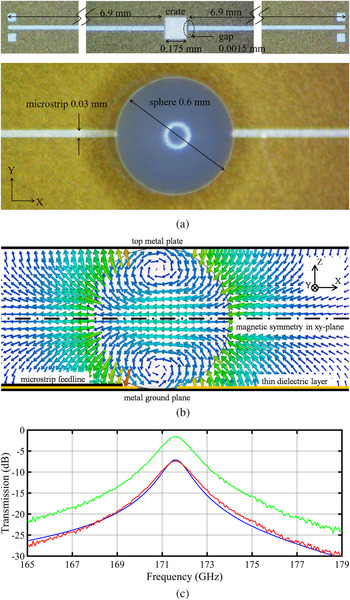
The key building block of the proposed filters is a spherical dielectric resonator coupled to a microstrip feed structure. The sphere locates precisely and self-aligns by a shallow crate etched into the microstrip board dielectric [Reference Cuenca, Alavi and Hesselbarth14]. The sphere could be glued into the crate where the crate would prevent the glue from dispersing. In the work described below, however, the sphere is not glued. The on-board area consumption of the resonator is minimum as compared to other geometries of dielectric resonators (Fig. 1(a)).
Microstrip-fed spherical dielectric resonator implementation. (a) Photos of the feed circuit on a thin-film board showing the ground-signal-ground pads for measurement, feedlines, etched crate for placement of the sphere, and zoomed view of sphere. (b) Side view of E-field in the xz-symmetry plane. (c) Measured (red) and simulated (blue) transmission including feedline loss. The green curve equals the red measured curve with feedline loss subtracted.

The strong fringing E-fields at the open end of the microstrip line excite the dielectric resonator in a resonance that is a hybrid version of the E101 mode [Reference Bohren and Huffman15]. A metal plate covers the sphere. The electric field configuration (Fig. 1(b)) shows a magnetic symmetry midway between the ground below and the metal plate atop the sphere. This prevents excitation of TEM parallel plate mode by the sphere.
In this work, an alumina ceramic sphere (material parameters extracted by fitting simulations to measurements: ɛr = 10.5, tan δ = 0.002) is used together with a thin-film board based on polyimide dielectric (datasheet values: ɛr = 3.5, tan δ = 0.0027) and gold metal. A long microstrip line connects the resonator to probe pads, which can be contacted with a ground-signal-ground probe. Measurement of the thin-film board with a laser microscope revealed a thickness of polyimide dielectric and gold metal of 18.5 ± 0.5 μm and 3.5 μm, respectively. Additional dimensions are given in Fig. 1(a).
Transmission magnitude measurement and the curve fitted by simulations are shown in Fig. 1(c). The measured total loss in the microstrip line feedlines (including both input and output side) is around 5.8 dB, which was extracted from separate measurements of long microstrip lines designed on the same thin-film wafer. This is depicted in Fig. 1(c), wherein the red curve is the raw measured data including the feedline loss and the green curve is the result of subtraction of the feedline loss from the raw measured data. The green curve peaks at 171.55 GHz with a transmission magnitude of −1.6 dB and a loaded Q-factor of 127. This translates to an unloaded Q-factor of ~750. This value carries some uncertainty by the underlying measurements, but relates well to the loss tangent of 0.002 and to data of similar resonators around 100 GHz [Reference Cuenca, Alavi and Hesselbarth14].
G-band three-resonator filter
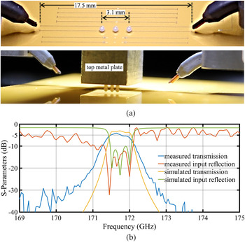
As shown in Fig. 2, three proximity-coupled spherical dielectric resonators (resonators and feed board as in section “Spherical dielectric resonator on planar circuit”) form a three-pole band-pass filter. Note that the loss of the long microstrip feedlines (measured separately) is subtracted from the results. The simulated insertion loss is around 3 dB, while the minimum measured insertion loss is 4 dB. The measured half-power transmission bandwidth is about 0.4%. The measured input reflection is below −10 dB.
Narrowband three-pole filter for G-band. (a) Photo of the dielectric resonator spheres with top metal cover removed, also showing long microstrip feedlines and probes (top). Side view of the assembled filter circuit (bottom). (b) Simulated and measured S-parameter magnitudes of the filter.

Reported in the literature, state-of-the-art narrowband filter designs around 170–180 GHz have been demonstrated by means of rectangular waveguide fabricated using deep reactive ion etching and bonding process having transmission bandwidth of 5.5% [Reference Xing-hai, Guang-cun, Yi-jia, Jing-fu, Hao-shen, Ying-bin, Chan-hung and Yong-sheng16]; planar circuits on thin film microstrip platform with transmission band of 5% [Reference Prigent, Rius, Blary, Happy, Lepilliet, Dambrine and Cappy17] and substrate integrated waveguide using photoimageable thick-film technology with 7% transmission bandwidth [Reference Stephens, Young and Robertson18]. Fourth-order band-pass filters of 1% bandwidth, operating at 450 GHz, have been reported [Reference Glubokov, Zhao, Campion, Shah and Oberhammer19]. They have been realized by stacking precision-aligned, etched-cavity silicon wafers, with gold plating resulting in unloaded resonator Q larger than 700. In comparison to these state-of-the-art works, the proposed dielectric resonator-based filter design has by far narrowest transmission bandwidth at similar insertion loss and also has a very small planar footprint.
W-band tunable two-resonator filter
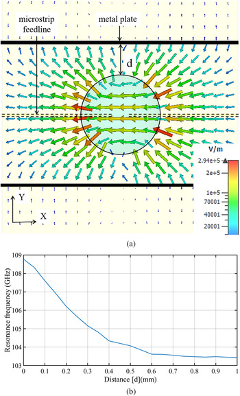
The fundamental transverse magnetic resonance mode of a dielectric sphere in free space is E101. According to Mie's theory [Reference Bohren and Huffman15], the resonance frequency of this E101 mode for an alumina sphere (ɛr = 10.15 [Reference Cuenca, Alavi and Hesselbarth14]) of diameter 1 mm is 128.6 GHz. When the dielectric sphere is implemented as an on-board resonator, as described in section “Spherical dielectric resonator on planar circuit”, a hybrid version of the E101 mode is excited which resonates at 103.5 GHz. The shift of resonance frequency is due to perturbations from substrate, groundplane, top metal plate, and microstrip feed. When further perturbation is applied in the form of metal plates placed parallel to the axis of the resonator structure, as depicted in Fig. 3, the resonance frequency can be tuned depending on the position of these metal plates.
Simulation results for mechanically tuning the resonance frequency of a spherical dielectric resonator (structure similar to the one described in section “Spherical dielectric resonator on planar circuit”, but with a sphere diameter of 1 mm). (a) E-field plot in the equatorial plane (top view) of the dielectric sphere. (b) Variation of resonance frequency with varying spacing d between metal plates and the dielectric resonator.

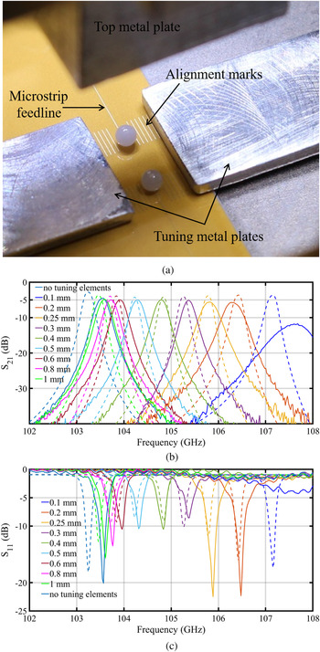
Using this principle, a tunable two-resonator narrowband filter is designed for operation around 105 GHz. As shown in Fig. 4(a), two alumina spheres of diameter 1 mm are coupled to microstrip feedlines. The widened open end of the microstrip line increases input/output coupling. Two moveable aluminum metal tuning plates encroach on the sides to change the resonance frequency of the resonators. The board contains alignment marks for visual control of the displacement of the tuning plates. In the experiment, mechanical positioners vary the positions of the tuning plates. The thickness of the tuning metal plates is smaller than the separation between the substrate and the top metal plate, thereby ensuring smooth movement.
W-band tunable two-resonator filter. (a) Photos and dimensions of the filter with top metal plate removed. (b) Measured (solid lines) and simulated (dashed lines) insertion loss and (c) input reflection for the filter with different separation distance of the metal plate from the sphere. Simulations reflect board dielectric thickness and metal thickness as in the measurements.

By varying the distance between resonator sphere and tuning plate from 1 to 0.1 mm, the pass-band frequency of the filter changes by 3.8%, from 103.5 GHz to around 107.5 GHz (Fig. 4(b)). Apart from the highest frequency tuned passband (plate distance of 0.1 mm, dark blue curves in Fig. 4(b)), the measured insertion loss varies between 4.5 dB (distance 1 mm) and 5.7 dB (distance 0.2 mm), which is about 1 dB more than in simulation. Note that the S-parameters (transmission, reflection) are corrected for the loss of the long microstrip feed lines (up to the beginning of the line end taper). For the closest distance (0.1 mm), measurements failed as here, small misalignments and tilts cause strong effects on filter performance, and could not be avoided. Simulations show that conduction loss in the tuning metal plates increases as they come closer to the resonating dielectric spheres, thereby increasing the pass-band insertion loss towards higher frequency. The measured input reflection follows a similar response as the simulations.
Discussions and comparison
The designed thickness of the polyimide layer of the thin-film board was 15 μm. However, the manufactured thickness was measured as 19 μm. Also, the gold metal turned out to be thicker than expected. By comparing the original simulations with those of the structures with the thicker board dielectric, for the W-band tunable filter, it is found that the original design shows much better performance. For the tuning range from 103.5 to 105.5 GHz, the simulation for the original board dimensions shows resonator loaded Q-factor well above 550 (measurements: around 400), and the minimum pass-band insertion loss is reduced to about 3 dB.
Comparing the proposed tunable resonator concept with alternative techniques (see in Table 1), the demonstrated tuning range is small but the achieved Q-factors are superior to all other published techniques with the possible exception of mechanically variable metallic waveguide cavities [Reference Kawamura, Shimotahira and Otani10].
State-of-the-art mm-wave tunable filter design.

Conclusion
A high-Q on-board dielectric resonator concept has been applied to a three-pole band-pass filter at 170 GHz and to a two-resonator, mechanically tunable band-pass filter operating around 105 GHz. Key characteristics at 170 GHz, verified by measurements, include unloaded Q-factor of ~750 at 170 GHz and insertion loss of <5 dB for the 0.4% bandwidth filter. Measurements of the tunable filter show a tuning range of about 3% for the two-resonator band-pass filter at 105 GHz, together with insertion loss varying between 4.5 and 5.7 dB. Selected improvements in the manufacturing precision of the thin-film board are likely to improve further the filter performance. The proposed filter technology can be implemented in the back-end-of-line layer stack of monolithically integrated circuits and thus shows large potential for mm-wave systems operating beyond 100 GHz.
Acknowledgement
This work was supported in part by the German Research Foundation (DFG) under grant HE6429/15.
 Utpal Dey was born in West Bengal, India, in 1989. He received M.Tech. degree from Indian Institute of Technology, Roorkee, Uttarakhand, India, in 2014 and the Ph.D. degree from University of Stuttgart, Stuttgart, Germany, in 2019. Between 2018 and 2019, he worked as a high-frequency hardware developer with Rohde & Schwarz, Munich, Germany. Since June 2019, he is a senior researcher at Institute of Radio Frequency Technology, University of Stuttgart, Stuttgart, Germany. His research interests include dielectric waveguides and near-field measurements in mm-wave frequency.
 Julio Gonzalez Marin was born in Madrid, Spain, in 1992. He received the B.Sc. and M.Sc. degrees in communications engineering from the Technical University of Madrid, Madrid, in 2014 and 2016, respectively. He worked with SENER, Getxo, Spain, from 2015 to 2016, where he was designing antenna components for space applications. Between 2016 and 2019, he worked as research assistant at Institute of Radio Frequency Technology, University of Stuttgart, Stuttgart, Germany. Since December, 2019, he is with Robert Bosch GmbH, Leonberg, Germany, working as an automotive radar developer. His research interest includes antennas for beam steering and power combining applications at millimeter waves.
 Jan Hesselbarth was born in Dresden, Germany, in 1970. He received the Doctorate degree from the Swiss Federal Institute of Technology (ETH Zürich), Zürich, Switzerland, in 2002. He worked as a Design Engineer with Huber + Suhner, Herisau, Switzerland, from 2001 to 2005, and a member of technical staff with Bell Labs, Dublin, Ireland, from 2005 to 2008. He then joined ETH Zürich as a Senior Researcher and a Lecturer. Since 2011, he has been a Professor with the Institute of Radio Frequency Technology, University of Stuttgart, Stuttgart, Germany. His research interests are in antennas and millimeter-wave circuits and packaging.


 Open access

