


1. Introduction
Injection of fuel or impurities in the form of small cryogenic pellets is an essential tool to sustain and control magnetic confinement fusion plasmas. The deposition of cold, dense material in this way may be used for fuelling, tailoring plasma parameter profiles, controlling edge localised modes and mitigating disruptions (Pégourié Reference Pégourié2007), as well as for diagnostic purposes (Kuteev et al. Reference Kuteev1994). In the form of shattered pellet injection (SPI) (Commaux et al. Reference Commaux, Baylor, Jernigan, Hollmann, Parks, Humphreys, Wesley and Yu2010), where a larger pellet is broken into a plume of shards before entering the plasma, it is foreseen as the main disruption mitigation system in ITER (Lehnen & ITER Disruption Mitigation Task Force, Reference Lehnen2021). In particular, for disruption mitigation, besides the requirement of a rapid delivery of the injected material, it is important that the material reaches deep into the plasma.
A pellet traversing the magnetically confined plasma is continuously heated by incident hot electrons, leading to an ablation of the pellet surface. The ablated material forms a cold, dense neutral cloud around the pellet, which then absorbs most of the incoming heat. The shielding is a self-regulated process, balancing the rate of ablation and the opacity of the ablation cloud. Close to the pellet the ablated material forms a neutral gas, while further away it ionises, forming a so-called plasmoid.
The plasmoid expands along the magnetic field lines, and drifts due to the inhomogeneous magnetic field (Lang et al. Reference Lang, Büchl, Kaufmann, Lang, Mertens, Müller and Neuhauser1997; Parks, Sessions & Baylor Reference Parks, Sessions and Baylor2000) – towards the low-field side (LFS) in a tokamak. Eventually, the pellet material homogenises over the flux surfaces and equilibrates with the background plasma. An accurate prediction of the resulting material deposition profile is essential, as it provides the basis for the design of pellet injection scenarios in future fusion reactors. Most previous modelling efforts have focused on the rate of ablation and the homogenisation processes (Pégourié Reference Pégourié2007), while treating the pellet motion as uniform and linear.
It was apparent already from the first pellet injection experiments that pellets can be deflected in the toroidal direction (Jorgensen, Sillesen & Oster Reference Jorgensen, Sillesen and Oster1975; Foster et al. Reference Foster, Colchin, Milora, Kim and Turnbull1977; Combs Reference Combs1993). It was soon established that this is caused by an asymmetric heating of the pellet, which intensifies the ablation over some region of the pellet surface and propels it in the opposite direction (Jones Reference Jones1978; Andersen Reference Andersen1985) – a phenomenon appropriately termed the pellet rocket effect.
In tokamaks, the ultimate cause of the heating asymmetry that causes a toroidal deflection is the plasma current (Andersen Reference Andersen1985; Kuteev Reference Kuteev1995; Waller et al. Reference Waller, Pégourié, Giruzzi, Huysmans, Garzotti and Géraud2003). In addition, pellet acceleration towards the LFS has been observed in tokamaks such as ASDEX (Wurden et al. Reference Wurden, Büchl, Hofmann, Lang, Loch, Rudyj and Sandmann1990), ASDEX Upgrade (Müller et al. Reference Müller1999; Kocsis et al. Reference Kocsis, Kálvin, Veres, Cierpka, Lang, Neuhauser and Wittman2004), HL-1 M (Liu et al. Reference Liu, Wang, Ding, Yan, Qian and Yan2002) and JET (Jachmich et al. Reference Jachmich2022; Kong et al. Reference Kong2024). This radial pellet rocket effect has also been observed in stellarators such as TJ-II (Medina-Roque Reference Medina-Roque2021), LHD (Mishra et al. Reference Mishra, Sakamoto, Matsuyama, Motojima and Yamada2011) and Wendelstein-7X (Baldzuhn et al. Reference Baldzuhn2019). In some stellarator studies, toroidal and poloidal rocket acceleration has been connected to energetic ions introduced by neutral beam injection (Morita et al. Reference Morita2002; Matsuyama et al. Reference Matsuyama, Pégourié, Sakamoto, Mishra, Motojima and Yamada2012; Panadero et al. Reference Panadero2018).
While a drag force between the drifting plasmoid and the neutral gas has been considered as a possible factor in the radial pellet acceleration (Polevoi & Shimada Reference Polevoi and Shimada2001), the dominant mechanism is likely to be the rocket effect. The required heating asymmetry arises due to the radial variation of plasma parameters, as well as asymmetric heat flux attenuation by the plasmoid, caused by the plasmoid drift. The latter has been modelled semi-analytically by Senichenkov, Rozhansky & Gusakov (Reference Senichenkov, Rozhansky and Gusakov2007), connecting the induced asymmetry in the ablation rate with the rocket force, while neglecting the pressure asymmetry at the pellet surface. This study projected a deceleration value above $10^6\,\textrm {m}\,\textrm{s}^{-2}$
for ITER, which could stop the pellet well before reaching the plasma core, indicating the particular importance of the rocket acceleration in reactor-scale devices. A semi-empirical model which depends on this pressure difference was developed by Szepesi et al. (Reference Szepesi, Kálvin, Kocsis and Lang2007), where the pressure asymmetry is treated as a free parameter.
$10^6\,\textrm {m}\,\textrm{s}^{-2}$
for ITER, which could stop the pellet well before reaching the plasma core, indicating the particular importance of the rocket acceleration in reactor-scale devices. A semi-empirical model which depends on this pressure difference was developed by Szepesi et al. (Reference Szepesi, Kálvin, Kocsis and Lang2007), where the pressure asymmetry is treated as a free parameter.
A recent three-dimensional (3-D) Lagrangian particle code simulation study by Samulyak et al. (Reference Samulyak, Yuan, Naitlho and Parks2021) and Samulyak (Reference Samulyak2023), which self-consistently computes many aspects of the pellet deposition process, including the pressure asymmetry, suggests that the radial pellet rocket effect yields acceleration values that can significantly affect pellet trajectories in ITER. Motivated by the potential importance of the rocket effect, we have developed a semi-analytical model to describe it, suitable for implementation into reduced numerical models. We treat the asymmetries as perturbations around the spherically symmetric solution of the widely used neutral gas shielding (NGS) model developed by Parks & Turnbull (Reference Parks and Turnbull1978). The pressure asymmetry is thus self-consistently calculated, in response to asymmetric heating boundary conditions.
The model is valid for any arbitrary source of electron heating asymmetry onto hydrogenic pellets, and was first presented in (Guth et al. Reference Guth, Vallhagen, Helander, Pusztai, Newton and Fülöp2025), where the rocket effect induced by the gradients in the background plasma parameters was studied. The purpose of this paper is to elaborate on how the rocket effect arises due to the drift of material ablated from the pellet and the corresponding asymmetric shielding of the incoming electron heat flux. Building on the plasmoid drift model presented by Vallhagen et al. (Reference Vallhagen, Pusztai, Helander, Newton and Fülöp2023), the corresponding shielding length variation across the field lines is evaluated geometrically. We close the article by providing quantitative predictions for the pellet penetration depth in scenarios representative of a medium-sized tokamak experiment and ITER.
2. Physical model of the pellet rocket effect
The underlying principle of the pellet rocket effect is that any asymmetric heating of the pellet and the ablation cloud will lead to a higher ablation and pressure on one side of the pellet, yielding a rocket-like propulsion accelerating the pellet towards the less heated side. In general, this phenomenon involves a complex, 3-D, nonlinear dynamics.
Initial treatments of pellet ablation used the standard NGS model, which made the geometrical assumption of spherically symmetric heating of the neutral cloud. This was soon replaced – see for example (Kuteev Reference Kuteev1995) – with the more physical assumption for magnetised plasmas, that the incoming electron heat flux is restricted to closely follow the magnetic field lines, so is deposited at the two diametrically opposed regions where the field lines intersect the neutral cloud. The larger thermal ion gyroradius allows heat to be deposited away from these regions (Kuteev Reference Kuteev1995), but it will be restricted to the periphery of the cloud (Pégourié et al. Reference Pégourié, Waller, Dumont, Eriksson, Garzotti, Géraud and Imbeaux2005), and the neutral cloud pressure is then expected to have a dipole structure, with the maxima along the magnetic field lines. Further improvements beyond the NGS model allowing for the build-up of an electrostatic sheath along the magnetic field line – see for example (Kuteev Reference Kuteev1995) and (Samulyak, Lu & Parks Reference Samulyak, Lu and Parks2007) – or considering the deformation of the pellet shape (Ishizaki et al. Reference Ishizaki, Parks, Nakajima and Okamoto2004), have indicated that this asymmetry of the lowest-order pressure may be reduced. The accumulation of physical effects has thus been found to underpin the surprising success of the simple spherically symmetric treatment of the ablation dynamics.
Treating the asymmetric pellet ablation dynamics as a linear perturbation around the spherically symmetric dynamics enables us to develop here a semi-analytical model for the pellet rocket effect. In this section, we consider the momentum transfer at the pellet surface, to connect the perturbed pressure to the force experienced by the pellet. We also include a discussion of the effect that would be produced by a dipolar correction to the lowest-order neutral cloud pressure.
We take a spherical pellet, of radius $r_{\text{p}}$
, surrounded by ablated neutral gas. The momentum of ablated particles which leave the pellet surface combines with the gas pressure acting on the pellet surface to generate the force on the pellet.
$r_{\text{p}}$
, surrounded by ablated neutral gas. The momentum of ablated particles which leave the pellet surface combines with the gas pressure acting on the pellet surface to generate the force on the pellet.
Illustration of how the pellet rocket force arises from both an asymmetry in pressure at the pellet surface (red shading) and an asymmetric ablation (arrows). Additionally, the coordinate system used throughout this paper is indicated. The unit vector $\hat {\boldsymbol{z}}$
denotes the axis of asymmetry. Here,
$\hat {\boldsymbol{z}}$
denotes the axis of asymmetry. Here, $\hat {\boldsymbol{r}}$
and
$\hat {\boldsymbol{r}}$
and $\hat {\boldsymbol{\theta }}$
denote the spherical coordinates, in which
$\hat {\boldsymbol{\theta }}$
denote the spherical coordinates, in which $\hat {\boldsymbol{\varphi }}$
would point into the paper. The pellet is modelled as a solid sphere of radius
$\hat {\boldsymbol{\varphi }}$
would point into the paper. The pellet is modelled as a solid sphere of radius $r_{\text{p}}$
.
$r_{\text{p}}$
.

Mathematically, the net force on the pellet is calculated by assuming local momentum conservation at each point $\boldsymbol{r}$
on the pellet surface
$\boldsymbol{r}$
on the pellet surface $S$
and integrating the stress tensor of the neutral gas as
$S$
and integrating the stress tensor of the neutral gas as
 \begin{equation} \boldsymbol{F} = - \iint _{S} \left ( \rho \boldsymbol{v} \boldsymbol{v} \boldsymbol{\cdot }\hat {\boldsymbol{r}} + p \hat {\boldsymbol{r}} \right ) \textrm{d}{S} , \end{equation}
with the mass density $\rho (\boldsymbol{r})$
, the flow velocity
$\rho (\boldsymbol{r})$
, the flow velocity $\boldsymbol{v}(\boldsymbol{r})$
and the pressure
$\boldsymbol{v}(\boldsymbol{r})$
and the pressure $p(\boldsymbol{r})$
. The minus sign indicates that this force is exerted on the pellet, while the surface normal unit vector
$p(\boldsymbol{r})$
. The minus sign indicates that this force is exerted on the pellet, while the surface normal unit vector $\hat {\boldsymbol{r}}$
points radially outwards. Let
$\hat {\boldsymbol{r}}$
points radially outwards. Let $\hat {\boldsymbol{z}}$
point along the axis of asymmetry towards the more strongly heated side, as illustrated in figure 1. Note that the illustration assumes no strong dipolar pressure contribution. The force can then be expressed as
$\hat {\boldsymbol{z}}$
point along the axis of asymmetry towards the more strongly heated side, as illustrated in figure 1. Note that the illustration assumes no strong dipolar pressure contribution. The force can then be expressed as
 \begin{equation} F = - \hat {\boldsymbol{z}} \boldsymbol{\cdot }\boldsymbol{F} = \iint _{S} [ \rho (\hat {\boldsymbol{z}}\boldsymbol{\cdot }\boldsymbol{v} \boldsymbol{v} \boldsymbol{\cdot }\hat {\boldsymbol{r}}) + p (\hat {\boldsymbol{z}}\boldsymbol{\cdot }\hat {\boldsymbol{r}}) ] \,\textrm{d}{S} . \end{equation}
In spherical coordinates $\{ r, \theta , \varphi \}$
, where
$\{ r, \theta , \varphi \}$
, where $\boldsymbol{v} = v_r \hat {\boldsymbol{r}} + v_\theta \hat {\boldsymbol{\theta }} + v_\varphi \hat {\boldsymbol{\varphi }}$
and the differential solid angle is
$\boldsymbol{v} = v_r \hat {\boldsymbol{r}} + v_\theta \hat {\boldsymbol{\theta }} + v_\varphi \hat {\boldsymbol{\varphi }}$
and the differential solid angle is $\textrm{d}{\varOmega } = \sin \theta \textrm{d}{\theta }\textrm{d}{\varphi }$
, the force integral reads
$\textrm{d}{\varOmega } = \sin \theta \textrm{d}{\theta }\textrm{d}{\varphi }$
, the force integral reads
 \begin{equation} F = r_{\text{p}}^2 \iint _{S} \left [ \rho v_r (v_r \cos \theta + v_\theta \sin \theta ) + p \cos \theta \right ] \textrm{d}{\varOmega } . \end{equation}
Retaining the asymmetries of the quantities appearing in (2.3) perturbatively allows us to write them as
 \begin{align} v_r(\boldsymbol{r}) &= v_0(r) + \delta {v_r}(r,\theta ,\varphi ), & v_\theta (\boldsymbol{r}) &= 0 + \delta {v_\theta }(r,\theta ,\varphi ), \nonumber \\ \rho (\boldsymbol{r}) &= \rho _0(r) + \delta {\rho }(r,\theta ,\varphi ), & p(\boldsymbol{r}) &= p_0(r) + \delta {p}(r,\theta ,\varphi ) , \end{align}
where subscript $0$
indicates a spherically symmetric component, while perturbations are denoted by
$0$
indicates a spherically symmetric component, while perturbations are denoted by $\delta$
.
$\delta$
.
Linearising the force in this perturbation and using $\int _0^\pi \cos \theta \textrm{d}{\theta } = 0$
leads to
$\int _0^\pi \cos \theta \textrm{d}{\theta } = 0$
leads to
 \begin{equation} F = r_{\text{p}}^2 \iint _S \left [\left ( \delta {\rho } v_0^2 + 2 \rho _0 v_0 \delta {v_r} + \delta {p} \right ) \cos \theta + \rho _0 v_0 \delta {v_\theta } \sin \theta \right ] \, \textrm{d}{\varOmega } . \end{equation}
The last term can be rewritten as a term proportional to $\cos \theta$
through integration by parts, which leads to
$\cos \theta$
through integration by parts, which leads to
 \begin{equation} F = r_{\text{p}}^2 \iint _S \big [\delta {\rho } v_0^2 + 2 \rho _0 v_0 \big ( \delta {v_r} - {\textstyle \int ^\theta _0} \delta {v_\theta }(\theta ') \textrm{d}{\theta '} \big ) + \delta {p}\big ] \cos \theta \textrm{d}{\varOmega } . \end{equation}
Consider now that $\cos \theta$
is the
$\cos \theta$
is the $l=1$
,
$l=1$
, $m=0$
mode of the spherical harmonics
$m=0$
mode of the spherical harmonics
 \begin{equation} Y_l^m(\theta ,\varphi ) = \sqrt {\frac {(l-m)!}{(l+m)!}} \mathcal{P}_l^m(\cos \theta ) \textrm{e}^{\textrm{i}m\varphi } , \end{equation}
with the associated Legendre polynomials $\mathcal{P}_l^m$
and which are orthogonal in the sense
$\mathcal{P}_l^m$
and which are orthogonal in the sense
 \begin{equation} \iint _S Y_l^m (Y_{l'}^{m'})^* \textrm{d}{\varOmega }=\frac {4 \pi }{2l+1} \delta _{ll'} \delta _{mm'} , \end{equation}
where $\delta _{ij}$
denotes the Kronecker delta. The integral in (2.6) can thus be immediately evaluated when expanding the asymmetric perturbations as
$\delta _{ij}$
denotes the Kronecker delta. The integral in (2.6) can thus be immediately evaluated when expanding the asymmetric perturbations as
 \begin{align} \delta {\rho }(r,\theta ,\varphi ) &= \rho _1(r)\cos \theta + \cdots , & \delta {p}(r,\theta ,\varphi ) &= p_1(r)\cos \theta + \cdots , \nonumber \\ \delta {v_r}(r,\theta ,\varphi ) &= v_{1,r}(r)\cos \theta + \cdots , & \int ^\theta _0 \delta {v_\theta }(r,\theta ',\varphi )\textrm{d}\theta ' &= v_{1,\theta }(r)\cos \theta + \cdots \, . \end{align}
Higher-order spherical harmonics do not contribute to the net force on the pellet, which can thus be calculated as
 \begin{equation} F = \frac {4 \pi r_{\text{p}}^2}{3} \left ( \rho _1 v_0^2 + 2 \rho _0 v_0 (v_{1,r} - v_{1,\theta }) + p_1 \right )_{r=r_{\text{p}}} . \end{equation}
This formula can also be understood physically. The ablation rate per unit area $g$
, i.e. the mass flux through the pellet surface, is
$g$
, i.e. the mass flux through the pellet surface, is
 \begin{align} g(\theta ) = \rho \boldsymbol{v} \boldsymbol{\cdot }\hat {\boldsymbol{r}} \approx ( \rho _0 v_0 + (\rho _1 v_0 + \rho _0 v_{1,r}) \cos \theta + \cdots )_{r=r_{\text{p}}} = g_0 + g_1 \cos \theta + \cdots \, . \end{align}
Therefore, the first two terms in (2.10) describe the force arising from asymmetric ablation. The third term corresponds to a force from a flow around the pellet surface. The last term $p_1$
describes the gas pressure asymmetry.
$p_1$
describes the gas pressure asymmetry.
Under the self-regulating shielding assumptions of the NGS model, the flow velocity at the pellet surface is zero (Parks & Turnbull Reference Parks and Turnbull1978). Therefore, the pellet rocket force is predominantly caused by the pressure asymmetry at the pellet surface $p_1(r_{\text{p}})$
and
$p_1(r_{\text{p}})$
and
 \begin{equation} F \approx \frac {4 \pi r_{\text{p}}^2}{3} p_1(r_{\text{p}}) . \end{equation}
The neglected terms are of the order of the square of the perturbed Mach number at the pellet surface. A similar expression was assumed in the empirical model developed by Szepesi et al. (Reference Szepesi, Kálvin, Kocsis and Lang2007).
Pellets will not be perfectly spherical, which we have assumed so far. Effects such as interaction with the wall of the guide tube directing the pellet to the plasma (Ishizaki et al. Reference Ishizaki, Parks, Nakajima and Okamoto2004) or tumbling motion of the pellets (Macaulay Reference Macaulay1994) may be expected to smooth the pellet shape. Calculating the expansion dynamics of the ablation cloud from an arbitrarily shaped pellet will be quite difficult, but it is possible to say something definite about pellets that are almost, but not quite, spherical, using the perturbative approach set out above. Consider a pellet whose boundary in spherical coordinates is given by
 \begin{equation} r(\theta ,\varphi ) = r_{\text{p}} \bigg (1+\sum _{l,m} \epsilon _{l,m}\mathcal{P}_l^m(\cos \theta ) \textrm{e}^{\textrm{i}m\varphi } \bigg ), \end{equation}
where the coefficients in the Fourier sum are small, $\epsilon _{l,m} \ll 1$
. If such a pellet is injected into an inhomogeneous plasma, the rocket effect can be calculated approximately by expanding the hydrodynamic equations in two small quantities: the asymmetry of the pellet surface and that of the ablation-cloud heating. Thanks to the linearity, the effects are additive to lowest order in the expansion. To this order, it is therefore sufficient to calculate the rocket force on a non-spherical pellet injected into a homogeneous plasma. The spherical symmetry of the ablation cloud is now broken by the boundary condition at the pellet surface, which is not symmetric. All unknown quantities can be expanded in spherical harmonics, and, thanks to linearity, the coefficients will be proportional to their counterparts in (2.13). Since the rocket force in the
$\epsilon _{l,m} \ll 1$
. If such a pellet is injected into an inhomogeneous plasma, the rocket effect can be calculated approximately by expanding the hydrodynamic equations in two small quantities: the asymmetry of the pellet surface and that of the ablation-cloud heating. Thanks to the linearity, the effects are additive to lowest order in the expansion. To this order, it is therefore sufficient to calculate the rocket force on a non-spherical pellet injected into a homogeneous plasma. The spherical symmetry of the ablation cloud is now broken by the boundary condition at the pellet surface, which is not symmetric. All unknown quantities can be expanded in spherical harmonics, and, thanks to linearity, the coefficients will be proportional to their counterparts in (2.13). Since the rocket force in the $\hat {\boldsymbol{z}}$
-direction only depends on the harmonic
$\hat {\boldsymbol{z}}$
-direction only depends on the harmonic $(l,m) = (1,0)$
, we conclude that
$(l,m) = (1,0)$
, we conclude that $F =c \epsilon _{1,0}$
, where the coefficient
$F =c \epsilon _{1,0}$
, where the coefficient $c$
can be determined by a simple physical argument. A pellet whose boundary is perturbed by this term only,
$c$
can be determined by a simple physical argument. A pellet whose boundary is perturbed by this term only, $r(\theta ,\varphi ) = r_{\text{p}} (1+\epsilon _{1,0}\cos \theta )$
, is still spherical, having a boundary that is simply displaced in the z-direction by the constant distance
$r(\theta ,\varphi ) = r_{\text{p}} (1+\epsilon _{1,0}\cos \theta )$
, is still spherical, having a boundary that is simply displaced in the z-direction by the constant distance $\epsilon _{1,0}r_{\text{p}}$
. As such, it is clear that the rocket force must vanish,
$\epsilon _{1,0}r_{\text{p}}$
. As such, it is clear that the rocket force must vanish, $c = 0$
. Thus the departure from perfect spherical symmetry does not affect the rocket force to first order in the smallness of the perturbation.
$c = 0$
. Thus the departure from perfect spherical symmetry does not affect the rocket force to first order in the smallness of the perturbation.
When we have the situation illustrated in figure 1, the rocket force will affect the motion of the pellet across the magnetic field lines. This is the case considered in § 5, where the impact of the rocket force on pellet penetration into a tokamak plasma is analysed. In this case, we note from the last term of (2.3) that any dipolar structure of the lowest-order pressure such as discussed at the beginning of this section will not affect the rocket force. This pressure structure can introduce asymmetry in the lowest-order ablation flows, but the flows will remain weak (subsonic) near the pellet surface, so no significant contribution would be expected from the first term in (2.3).
Another case of interest is when the pellet is heated asymmetrically along the magnetic field lines, so the $\hat {\boldsymbol{z}}$
axis is aligned along the field direction and the rocket force drives the pellet along the field lines. This can be the case when multiple pellet fragments exist in close proximity on the same field line, but in this particular situation we also expect a dipolar structure of the lowest-order pressure to develop and to have a significant effect. This is beyond the scope of the semi-analytic model presented here.
$\hat {\boldsymbol{z}}$
axis is aligned along the field direction and the rocket force drives the pellet along the field lines. This can be the case when multiple pellet fragments exist in close proximity on the same field line, but in this particular situation we also expect a dipolar structure of the lowest-order pressure to develop and to have a significant effect. This is beyond the scope of the semi-analytic model presented here.
In response to the rocket force (2.12), a pellet with mean density $\rho$
will experience an acceleration
$\rho$
will experience an acceleration
 \begin{equation} \dot {v}_z = - \frac {p_1}{\rho r_p}, \end{equation}
which will significantly affect the trajectory over the time $\Delta t$
if
$\Delta t$
if $|\dot {v}_z| \gt v_z / \Delta t$
. In particular, if the pellet travels the distance
$|\dot {v}_z| \gt v_z / \Delta t$
. In particular, if the pellet travels the distance $L$
in the
$L$
in the $z$
-direction, the rocket force is important if
$z$
-direction, the rocket force is important if $|\dot {v}_z L / v_z^2| \gt 1$
, i.e.
$|\dot {v}_z L / v_z^2| \gt 1$
, i.e.
 \begin{equation} p_1 \gt \frac {\rho r_p v_z^2}{L}. \end{equation}
For typical pellet parameters $v_z \sim 10^3$
m s–1,
$v_z \sim 10^3$
m s–1, $r_p \sim 10^{-3}$
m,
$r_p \sim 10^{-3}$
m, $L = 1$
m and
$L = 1$
m and $\rho \sim 10^2$
kg m–
$\rho \sim 10^2$
kg m– $^3$
, a pressure asymmetry as small as 1 atm is thus significant. This value is far smaller than the typical pressure of an ablation cloud, which justifies the linearisation undertaken above.
$^3$
, a pressure asymmetry as small as 1 atm is thus significant. This value is far smaller than the typical pressure of an ablation cloud, which justifies the linearisation undertaken above.
The major challenge in modelling the pellet rocket effect is to calculate $p_1$
given the pellet and background plasma parameters. An important contribution to the pressure asymmetry is the variation of the plasmoid shielding across the magnetic field, which will be described in the next section.
$p_1$
given the pellet and background plasma parameters. An important contribution to the pressure asymmetry is the variation of the plasmoid shielding across the magnetic field, which will be described in the next section.
3. Shielding asymmetry due to plasmoid drift
Hot electrons incoming from the background plasma deposit their energy along their path towards the pellet, heating both the neutral cloud and the ionised plasmoid. Even though the major part of the heating occurs in the neutral gas close to the pellet, the energy deposition in the plasmoid is important in introducing an asymmetry of the heat flux reaching the neutral cloud. This plasmoid shielding of the incoming electron heat flux depends mainly on the integrated density along the electron path through the plasmoid.
In § 3.1 we quantify how the drift of the ionised ablation material leads to a varying shielding length across the magnetic field lines, which in turn affects the pellet ablation dynamics. In § 3.2 we describe a model for calculating the effective heat flux and electron energy arriving at the neutral cloud and their asymmetries, which will later be used as boundary conditions for the neutral ablation-cloud dynamics.
3.1. Geometry of the plasmoid boundary
The flow velocity at the boundary of the neutral ablation cloud rapidly drops as the material begins to be ionised (Ishizaki et al. Reference Ishizaki, Nakajima, Okamoto and Parks2003; Pégourié Reference Pégourié2007; Samulyak et al. Reference Samulyak, Lu and Parks2007; Bosviel, Parks & Samulyak Reference Bosviel, Parks and Samulyak2021). Beyond this, at the ionisation radius $r_{\text{i}}$
(not to be confused with the sonic radius
$r_{\text{i}}$
(not to be confused with the sonic radius $r_\star$
much closer to the pellet), the ablated material can be considered fully ionised and forms the plasmoid ablation cloud. The dominant dynamics of the plasmoid is its expansion along a flux tube at the speed of sound
$r_\star$
much closer to the pellet), the ablated material can be considered fully ionised and forms the plasmoid ablation cloud. The dominant dynamics of the plasmoid is its expansion along a flux tube at the speed of sound
 \begin{equation} c_{\text{s}} = \sqrt {\frac {(\gamma _e \langle Z \rangle + \gamma _i) T_{\text{pl}}}{\langle m_i \rangle }} , \end{equation}
where $T_{\text{pl}}$
is the plasmoid temperature,
$T_{\text{pl}}$
is the plasmoid temperature, $\langle m_i \rangle$
and
$\langle m_i \rangle$
and $\langle Z\rangle$
denote the (density weighted) average ion mass and charge number, respectively, and the adiabatic indices of electrons and ions are
$\langle Z\rangle$
denote the (density weighted) average ion mass and charge number, respectively, and the adiabatic indices of electrons and ions are $\gamma _e = 1$
,
$\gamma _e = 1$
, $\gamma _i = 3$
(Vallhagen et al. Reference Vallhagen, Pusztai, Helander, Newton and Fülöp2023).
$\gamma _i = 3$
(Vallhagen et al. Reference Vallhagen, Pusztai, Helander, Newton and Fülöp2023).
Let us consider the plasmoid dynamics in the instantaneous frame of a pellet injected in the opposite direction to the plasmoid drift – that is, towards the high-field side in tokamaks. The ionised ablated material initially moves at the laboratory frame pellet speed $v_{\text{p}}$
towards the LFS. The
$v_{\text{p}}$
towards the LFS. The $\boldsymbol{E} \times \boldsymbol{B}$
-drift gradually accelerates material across the field in the same direction and the plasmoid bends outwards compared with the flux surfaces, as illustrated in figure 2. For a short time following ionisation, the plasmoid material undergoes a constant acceleration (Vallhagen et al. Reference Vallhagen, Pusztai, Helander, Newton and Fülöp2023).
$\boldsymbol{E} \times \boldsymbol{B}$
-drift gradually accelerates material across the field in the same direction and the plasmoid bends outwards compared with the flux surfaces, as illustrated in figure 2. For a short time following ionisation, the plasmoid material undergoes a constant acceleration (Vallhagen et al. Reference Vallhagen, Pusztai, Helander, Newton and Fülöp2023).
 \begin{equation} \dot {v}_{\text{pl}} = \frac {2 (1+ \langle Z \rangle )}{\langle m_i \rangle R_{\text{m}}} \left ( T_{\text{pl}} - \frac {2n_{\text{bg}}}{(1+ \langle Z \rangle )n_{\text{pl}}} T_{\text{bg}} \right )\!, \end{equation}
where $T_{\text{bg}}$
and
$T_{\text{bg}}$
and $n_{\text{bg}}$
are the electron temperature and density of the background plasma,
$n_{\text{bg}}$
are the electron temperature and density of the background plasma, $n_{\text{pl}}$
is the electron density in the plasmoid and
$n_{\text{pl}}$
is the electron density in the plasmoid and $R_{\text{m}}$
is the local value of the major radius. The plasmoid electron density can be estimated using particle conservation considerations
$R_{\text{m}}$
is the local value of the major radius. The plasmoid electron density can be estimated using particle conservation considerations
 \begin{equation} n_{\text{pl}} = \frac { \mathcal{G}}{2 \langle m_i \rangle c_{\text{s}} \pi r_{\text{i}}^2}, \end{equation}
where the outflow from the pellet through a cross-sectional area $\pi r_{\text{i}}^2$
is determined by the mass ablation rate
$\pi r_{\text{i}}^2$
is determined by the mass ablation rate $\mathcal{G}$
.
$\mathcal{G}$
.
Illustration of the plasmoid shielding asymmetry of the ablation cloud in figure 1. The drift towards the LFS (negative $z$
direction) induces a shorter shielding length at the high-field side. Note that the proportions in the figure are not realistic: the pellet is much smaller than the neutral cloud that, in turn, is much smaller than the plasmoid shielding length.
$z$
direction) induces a shorter shielding length at the high-field side. Note that the proportions in the figure are not realistic: the pellet is much smaller than the neutral cloud that, in turn, is much smaller than the plasmoid shielding length.

Since the particles, once ionised, stop their motion in the positive $\hat {\boldsymbol{z}}$
-direction nearly instantaneously, the plasmoid boundary
$\hat {\boldsymbol{z}}$
-direction nearly instantaneously, the plasmoid boundary $z(x)$
, as depicted in figure 2 with the pellet at the origin, is determined by the trajectory of particles which are ionised at
$z(x)$
, as depicted in figure 2 with the pellet at the origin, is determined by the trajectory of particles which are ionised at $\{x=0, z=r_{\text{i}}\}$
. Very approximately, these particles follow the equation of motion
$\{x=0, z=r_{\text{i}}\}$
. Very approximately, these particles follow the equation of motion
 \begin{equation} \boldsymbol{r}(t) = (\pm c_{\text{s}} t) \hat {\boldsymbol{x}} + \left (r_{\text{i}} - v_{\text{p}} t - \frac {1}{2} \dot {v}_{\text{pl}} t^2 \right ) \hat {\boldsymbol{z}} . \end{equation}
The shielding length $s(z)$
along a field line at position
$s(z)$
along a field line at position $z$
is the distance from the plasmoid boundary to the neutral ablation-cloud boundary, which lies at
$z$
is the distance from the plasmoid boundary to the neutral ablation-cloud boundary, which lies at $x = \pm \sqrt {r_{\text{i}}^2 - z^2}$
. Therefore, assuming constant acceleration, the shielding length can be estimated by eliminating the time dependence from (3.4), yielding
$x = \pm \sqrt {r_{\text{i}}^2 - z^2}$
. Therefore, assuming constant acceleration, the shielding length can be estimated by eliminating the time dependence from (3.4), yielding
 \begin{equation} s(z) = c_{\text{s}} \left ( - \frac {v_{\text{p}}}{\dot {v}_{\text{pl}}} + \sqrt {\left (\frac {v_{\text{p}}}{\dot {v}_{\text{pl}}}\right )^2 + \frac {2}{\dot {v}_{\text{pl}}}( r_{\text{i}} - z)} \right ) - \sqrt {r_{\text{i}}^2 - z^2} . \end{equation}
The spherically symmetric part of the ablation is given by the central shielding length
 \begin{equation} s_0 = s(z=0) = c_{\text{s}} \left ( - \frac {v_{\text{p}}}{\dot {v}_{\text{pl}}} + \sqrt {\left (\frac {v_{\text{p}}}{\dot {v}_{\text{pl}}}\right )^2 + \frac {2}{\dot {v}_{\text{pl}}} r_{\text{i}}} \right ) - r_{\text{i}} . \end{equation}
The asymmetry in the neutral ablation-cloud heating is determined by the shielding length variation, $\delta {s}$
, across the field lines hitting the pellet. It might appear a reasonable choice to consider the shielding length variation across the entire neutral ablation cloud, however, this would largely overestimate the degree of asymmetry. The reason is that the vast majority of the heat deposition happens close to the pellet surface, thus the field lines relevant for the asymmetry are the ones spanning the range
$\delta {s}$
, across the field lines hitting the pellet. It might appear a reasonable choice to consider the shielding length variation across the entire neutral ablation cloud, however, this would largely overestimate the degree of asymmetry. The reason is that the vast majority of the heat deposition happens close to the pellet surface, thus the field lines relevant for the asymmetry are the ones spanning the range $z \in [-\delta {r}, \delta {r}]$
, with
$z \in [-\delta {r}, \delta {r}]$
, with $r_{\text{p}} \leqslant \delta {r} \lesssim 1.5 r_{\text{p}}$
. Due to the geometric approximation employed by the NGS model
$r_{\text{p}} \leqslant \delta {r} \lesssim 1.5 r_{\text{p}}$
. Due to the geometric approximation employed by the NGS model $-\boldsymbol{\nabla }\boldsymbol{\cdot }\boldsymbol{q} \approx \partial q / \partial r$
, which is detailed further in § 4, these field lines should correspond to the full angular range
$-\boldsymbol{\nabla }\boldsymbol{\cdot }\boldsymbol{q} \approx \partial q / \partial r$
, which is detailed further in § 4, these field lines should correspond to the full angular range $\theta \in [0, \pi ]$
. As the shielding length varies nearly linearly across the narrow
$\theta \in [0, \pi ]$
. As the shielding length varies nearly linearly across the narrow $z$
range of interest, we may write
$z$
range of interest, we may write
 \begin{equation} \delta {s}(z) = \bigg . \frac {\textrm{d} s}{\textrm{d} z} \bigg |_{z=0} \!\!\!\! \boldsymbol{\cdot }\delta {z} = \bigg . \frac {\textrm{d} s}{\textrm{d} z} \bigg |_{z=0} \!\!\!\! \boldsymbol{\cdot }\delta {r} \cos {\theta } , \end{equation}
with
 \begin{equation} \bigg . \frac {\textrm{d} s}{\textrm{d} z} \bigg |_{z=0} = \frac {- c_{\text{s}}}{\sqrt {v_{\text{p}}^2 + 2 \dot {v}_{\text{pl}} r_{\text{i}}}} . \end{equation}
3.2. Shielding of hot electrons through the plasmoid
The full dynamics of hot electrons losing energy while traversing a colder plasma involves multiple different mechanisms. A rigorous description of this heat flux shielding of the plasmoid is ultimately kinetic, and it is outside the scope of this paper. Here, we approximate the heat flux attenuation by assuming that electrons with a mean free path, $\lambda _{\text{mfp}}$
, shorter than the path length,
$\lambda _{\text{mfp}}$
, shorter than the path length, $d$
, they travel through the plasmoid, fully deposit their energy inside the plasmoid. Those electrons satisfying
$d$
, they travel through the plasmoid, fully deposit their energy inside the plasmoid. Those electrons satisfying $\lambda _{\text{mfp}}\gt d$
are, on the other hand, assumed to be completely unaffected by the plasmoid and retain their thermal kinetic energy from the background plasma.
$\lambda _{\text{mfp}}\gt d$
are, on the other hand, assumed to be completely unaffected by the plasmoid and retain their thermal kinetic energy from the background plasma.
The path length of an electron trajectory $d$
, as it traverses the shielding length
$d$
, as it traverses the shielding length $s$
, is
$s$
, is
 \begin{equation} d = \frac {s}{\xi } , \end{equation}
where $\xi =v_\|/v_e$
is the pitch-angle cosine defined by the electron speed
$\xi =v_\|/v_e$
is the pitch-angle cosine defined by the electron speed $v_e$
and its component,
$v_e$
and its component, $v_\|$
, parallel to the magnetic field. The mean free path of hot electrons in the plasmoid is determined by their collisions with the cold and dense electron population of the plasmoid
$v_\|$
, parallel to the magnetic field. The mean free path of hot electrons in the plasmoid is determined by their collisions with the cold and dense electron population of the plasmoid
 \begin{equation} \lambda _{\text{mfp}} = \frac {v_e}{\nu _{ee}} = \frac {4 \pi \varepsilon _0^2 m_e^2 v_e^4}{n_{\text{pl}} e^4 \ln \varLambda } = \left ( \frac {v_e}{v_{\text{th}}} \right )^4 \lambda _T , \end{equation}
with the collision frequency $\nu _{ee}$
, the cold electron density
$\nu _{ee}$
, the cold electron density $n_{\text{pl}}$
in the plasmoid and the electron mass
$n_{\text{pl}}$
in the plasmoid and the electron mass $m_e$
(Helander & Sigmar Reference Helander and Sigmar2005). For convenience, we define the mean free path
$m_e$
(Helander & Sigmar Reference Helander and Sigmar2005). For convenience, we define the mean free path $\lambda _T$
at the thermal velocity
$\lambda _T$
at the thermal velocity $v_{\text{th}} = \sqrt {2T_{\text{bg}}/m_e}$
. The Coulomb logarithm is
$v_{\text{th}} = \sqrt {2T_{\text{bg}}/m_e}$
. The Coulomb logarithm is
 \begin{equation} \ln \varLambda = \ln \left ( \lambda _{\text{D}} \boldsymbol{\cdot }b_{\text{min}}^{-1} \right ) = \ln \left ( \sqrt {\frac {\varepsilon _0 T_{\text{pl}}}{n_{\text{pl}} e^2}} \boldsymbol{\cdot }\left ( \frac {\langle Z \rangle e^2}{2 \pi \varepsilon _0 m_e v_{\text{th}}^2} \right )^{-1} \right ). \end{equation}
The condition for an electron to pass through the plasmoid unaffected (i.e. $d\lt \lambda _{\text{mfp}}$
) can be written in terms of a critical velocity
$d\lt \lambda _{\text{mfp}}$
) can be written in terms of a critical velocity $v_{\text{c}}$
as
$v_{\text{c}}$
as
 \begin{equation} v_e \gt v_{\text{c}} \quad \text{with} \ v_{\text{c}} = \left ( \frac {s}{\xi \lambda _T} \right )^{{1}/{4}} v_{\text{th}} . \end{equation}
We assume that the background electron distribution is Maxwellian $ f_{\text{M}}(\boldsymbol{v}_e) = ( \sqrt {\pi } v_{\text{th}} )^{-3} \exp [-(v_e/v_{\text{th}})^2 ]$
. Then, the heat flux reaching the neutral ablation cloud, which will serve as a boundary condition for the NGS model, can be estimated by integrating
$ f_{\text{M}}(\boldsymbol{v}_e) = ( \sqrt {\pi } v_{\text{th}} )^{-3} \exp [-(v_e/v_{\text{th}})^2 ]$
. Then, the heat flux reaching the neutral ablation cloud, which will serve as a boundary condition for the NGS model, can be estimated by integrating $q(\boldsymbol{v}_e)$
over the velocities sufficient to pass through the plasmoid
$q(\boldsymbol{v}_e)$
over the velocities sufficient to pass through the plasmoid
 \begin{gather} q_{\text{pl}} = \underset {\substack {v_e \gt v_{\text{c}} \\ \xi \in [0,1]}}{\iiint } \xi v_e \frac {m_e v_e^2}{2} n_{\text{bg}} f_{\text{M}}(\boldsymbol{v}_e) \textrm{d}^{3}{v_e} \, . \end{gather}
This integral can be evaluated in a closed form by introducing ${u = v_e/v_{\text{th}}} \Rightarrow {u(v_{\text{c}}) = ( \xi \alpha )^{-{1}/{4}}}$
, with
${u = v_e/v_{\text{th}}} \Rightarrow {u(v_{\text{c}}) = ( \xi \alpha )^{-{1}/{4}}}$
, with $\alpha = \lambda _T/s$
. The result is
$\alpha = \lambda _T/s$
. The result is
 \begin{equation} q_{\text{pl}}(s) = \underbrace {2 \sqrt {\frac {T_{\text{bg}}^3}{2 \pi m_e}} n_{\text{bg}}}_{q_{\text{Parks}}} \underbrace {\frac {1}{\alpha ^2}\left [ e^{{-1}/{\sqrt {\alpha }}}\left (-\frac {1}{2}\sqrt {\alpha }+\frac {1}{2}\alpha +\alpha ^{3/2}+\alpha ^2\right )-\frac {1}{2}\textrm{Ei}\left (-\frac {1}{\sqrt {\alpha }}\right )\right ]}_{f_q(\alpha )} , \end{equation}
with the exponential integral $\textrm{Ei}(x) = - \int _{-x}^{\infty } \exp (-t)/t \textrm{d}{t}$
. Consequently, the heat flux without any plasmoid shielding
$\textrm{Ei}(x) = - \int _{-x}^{\infty } \exp (-t)/t \textrm{d}{t}$
. Consequently, the heat flux without any plasmoid shielding $q_{\text{Parks}}$
, as assumed by Parks & Turnbull (Reference Parks and Turnbull1978), is scaled down in our model by the shielding length-dependent dimensionless function,
$q_{\text{Parks}}$
, as assumed by Parks & Turnbull (Reference Parks and Turnbull1978), is scaled down in our model by the shielding length-dependent dimensionless function, $f_q(\alpha )$
.
$f_q(\alpha )$
.
We then define the effective electron energy reaching the neutral ablation cloud as
 \begin{equation} E_{\text{pl}} = \frac {q_{\text{pl}}}{\varGamma _{\text{pl}}} , \end{equation}
where the effective particle flux $\varGamma _{\text{pl}}$
of electrons, defined analogously to
$\varGamma _{\text{pl}}$
of electrons, defined analogously to $q_{\text{pl}}$
, is
$q_{\text{pl}}$
, is
 \begin{equation} \varGamma _{\text{pl}}(s) = \underset {\substack {v_e \gt v_{\text{c}} \xi \in [0,1]}}{\iiint } \xi v_e n_{\text{bg}} f_{\text{M}}(\boldsymbol{v}_e) \textrm{d}^{3}{v_e} . \end{equation}
The result is again a scaling of the effective energy, $E_{\text{Parks}}$
, assumed by Parks & Turnbull (Reference Parks and Turnbull1978), by a dimensionless function
$E_{\text{Parks}}$
, assumed by Parks & Turnbull (Reference Parks and Turnbull1978), by a dimensionless function $f_E(\alpha )$
, as
$f_E(\alpha )$
, as
 \begin{equation} E_{\text{pl}}(s) = \underbrace {2 T_{\text{bg}}}_{E_{\text{Parks}}} \underbrace {\left [ \frac { e^{{-1}/{\sqrt {\alpha }}}\left (-\frac {1}{2}\sqrt {\alpha }+\frac {1}{2}\alpha +\alpha ^{3/2}+\alpha ^2\right )-\frac {1}{2}\textrm{Ei}\left (-\frac {1}{\sqrt {\alpha }}\right )} {e^{{-1}/{\sqrt {\alpha }}}\left (+\frac {1}{2}\sqrt {\alpha }-\frac {1}{2}\alpha +\alpha ^{3/2}+\alpha ^2\right ) + \frac {1}{2}\textrm{Ei}\left (-\frac {1}{\sqrt {\alpha }}\right )} \right ]}_{f_E(\alpha )} . \end{equation}
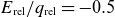
The dimensionless functions $f_q(\alpha )$
and
$f_q(\alpha )$
and $f_E(\alpha )$
are shown in figure 3. For a stronger shielding, i.e. decreasing
$f_E(\alpha )$
are shown in figure 3. For a stronger shielding, i.e. decreasing $\alpha$
, the heat flux is reduced, while the effective energy is enhanced, as the shielding filters out a broader range of energies, allowing only more energetic electrons to pass through the plasmoid.
$\alpha$
, the heat flux is reduced, while the effective energy is enhanced, as the shielding filters out a broader range of energies, allowing only more energetic electrons to pass through the plasmoid.
Scaling functions for the heat flux and energy boundary conditions due to plasmoid shielding, inversely dependent on the shielding length $s$
.
$s$
.

With these shielding length-dependent expressions for the heat flux and effective energy reaching the ablated neutral cloud, we are in the position to provide the boundary conditions for the ablation model. Those for the spherically symmetric component (the basic NGS model) are obtained by evaluating the flux and energy at the central shielding length $s_0$
as
$s_0$
as
 \begin{align} q_{\text{bc0}} &= q_{\text{pl}}(s_0) = q_{\text{Parks}} f_q(\alpha _0), \nonumber\\[4pt] E_{\text{bc0}} &= E_{\text{pl}}(s_0) = E_{\text{Parks}} f_E(\alpha _0), \end{align}
with $\alpha _0 = \lambda _T/s_0$
and
$\alpha _0 = \lambda _T/s_0$
and $s_0$
is given by (3.6). One subtlety that needs to be addressed is that the plasmoid shielding depends on the ablation rate
$s_0$
is given by (3.6). One subtlety that needs to be addressed is that the plasmoid shielding depends on the ablation rate $\mathcal{G}$
through the plasmoid density
$\mathcal{G}$
through the plasmoid density $n_{\text{pl}}$
in (3.3). However,
$n_{\text{pl}}$
in (3.3). However, $\mathcal{G}$
, whilst it has here the spherically symmetric form given by the NGS model (confirmation that our numerical method does recover this is detailed in (Guth Reference Guth2024)), depends itself on the boundary conditions provided by (3.18). Therefore, the plasmoid shielding (
$\mathcal{G}$
, whilst it has here the spherically symmetric form given by the NGS model (confirmation that our numerical method does recover this is detailed in (Guth Reference Guth2024)), depends itself on the boundary conditions provided by (3.18). Therefore, the plasmoid shielding ( $q_{\text{bc0}}$
,
$q_{\text{bc0}}$
, $E_{\text{bc0}}$
) has to be calculated in a self-consistent iteration until the ablation rate
$E_{\text{bc0}}$
) has to be calculated in a self-consistent iteration until the ablation rate $\mathcal{G}$
is converged. Then, the
$\mathcal{G}$
is converged. Then, the $Y_1^0(\theta ,\varphi )=\cos \theta$
components of the flux
$Y_1^0(\theta ,\varphi )=\cos \theta$
components of the flux $q_{\text{pl}}$
and energy
$q_{\text{pl}}$
and energy $E_{\text{pl}}$
provide the boundary conditions for the asymmetric component of the ablation dynamics. In the next section, we detail the evaluation of this asymmetric dynamics in the neutral cloud and determine a semi-analytic form for the resulting pressure asymmetry on the pellet surface, in terms of the degree of asymmetry in the boundary conditions.
$E_{\text{pl}}$
provide the boundary conditions for the asymmetric component of the ablation dynamics. In the next section, we detail the evaluation of this asymmetric dynamics in the neutral cloud and determine a semi-analytic form for the resulting pressure asymmetry on the pellet surface, in terms of the degree of asymmetry in the boundary conditions.
4. Asymmetrically heated neutral gas ablation cloud
To determine the pressure asymmetry at the pellet surface, the radial dynamics of the neutral gas cloud must be modelled. We start from the same equations as the widely used NGS model (Parks & Turnbull Reference Parks and Turnbull1978), which has been shown to provide reasonable predictions of experimentally observed pellet ablation rates (Pégourié Reference Pégourié2007). We outline the details necessary to derive our model here and describe the asymmetric ablation dynamics. For any further details of the spherically symmetric NGS model, we refer the reader to (Parks & Turnbull Reference Parks and Turnbull1978) or (Guth Reference Guth2024).
4.1. Asymmetric NGS model
The neutral gas ablation cloud is considered as a quasi-steady-state ideal gas governed by conservation of mass, momentum and energy according to
 \begin{align} &\frac {\rho }{m} = \frac {p}{T} &\text{(ideal gas law)} ,\\[-10pt]\nonumber \end{align}
 \begin{align} &\boldsymbol{\nabla } \boldsymbol{\cdot }(\rho \boldsymbol{v}) = 0 &\text{(mass conservation)} ,\\[-10pt]\nonumber \end{align}
 \begin{align} &\rho (\boldsymbol{v} \boldsymbol{\cdot }\boldsymbol{\nabla }) \boldsymbol{v} = - \boldsymbol{\nabla } p &\text{(momentum conservation)} ,\\[-10pt]\nonumber \end{align}
 \begin{align} &\boldsymbol{\nabla } \boldsymbol{\cdot }\left [\left ( \frac {\rho v^2}{2} + \frac {\gamma p}{\gamma - 1} \right ) \boldsymbol{v}\right ] = - Q \boldsymbol{\nabla } \boldsymbol{\cdot }\boldsymbol{q} &\text{(energy conservation)}. \end{align}
The fluid quantities describing the gas dynamics at each point $\boldsymbol{r}$
are the mass density
$\boldsymbol{r}$
are the mass density $\rho$
, the pressure
$\rho$
, the pressure $p$
, the temperature
$p$
, the temperature $T$
and the flow velocity
$T$
and the flow velocity $\boldsymbol{v}$
. The gas is taken to consist of ablated molecules of mass
$\boldsymbol{v}$
. The gas is taken to consist of ablated molecules of mass $m$
and adiabatic index
$m$
and adiabatic index $\gamma$
. The right-hand side of (4.4) represents the heat source and is assumed to be a fraction,
$\gamma$
. The right-hand side of (4.4) represents the heat source and is assumed to be a fraction, $Q \approx {0.6}{-} {0.7}$
, of the loss of energy flux
$Q \approx {0.6}{-} {0.7}$
, of the loss of energy flux $\boldsymbol{q}(\boldsymbol{r})$
of the incoming electrons (Parks & Turnbull Reference Parks and Turnbull1978). The dominant approximations of the NGS model are in fact the following assumptions made on the form of this heat source.
$\boldsymbol{q}(\boldsymbol{r})$
of the incoming electrons (Parks & Turnbull Reference Parks and Turnbull1978). The dominant approximations of the NGS model are in fact the following assumptions made on the form of this heat source.
First, the energy flux carried by the most energetic electrons is in reality directed along the magnetic field lines, thus passing through the neutral gas cloud in a nearly straight line. In the NGS model, this is approximated by an equivalent radial path, so that $-\boldsymbol{\nabla }\boldsymbol{\cdot }\boldsymbol{q} \approx {\partial q}/{\partial r}$
. Since most of the heating occurs close to the pellet, this mapping dictates that the asymmetry in
$-\boldsymbol{\nabla }\boldsymbol{\cdot }\boldsymbol{q} \approx {\partial q}/{\partial r}$
. Since most of the heating occurs close to the pellet, this mapping dictates that the asymmetry in $q$
has to be determined by only considering field lines that significantly affect the pellet heating, as discussed in § 3.1.
$q$
has to be determined by only considering field lines that significantly affect the pellet heating, as discussed in § 3.1.
Second, the energy distribution of the incident electrons is replaced by a single effective energy $E(\boldsymbol{r})$
, which we take to be the ratio of the unidirectional energy flux and particle flux facing the pellet cloud. This enables calculation of the incident electron dynamics through the differential equations
$E(\boldsymbol{r})$
, which we take to be the ratio of the unidirectional energy flux and particle flux facing the pellet cloud. This enables calculation of the incident electron dynamics through the differential equations
 \begin{align} &\frac {\partial E}{\partial r} = 2 \frac {\rho }{m} L(E) &\text{(electron energy loss)} ,\\[-10pt]\nonumber \end{align}
 \begin{align} &\frac {\partial q}{\partial r} = \frac {\rho }{m} q \varLambda (E) &\text{(heat flux attenuation)} , \end{align}
where $L(E)$
and
$L(E)$
and $\varLambda (E)$
are empirical functions describing the energy loss and scattering of electrons passing through a hydrogenic gas (Parks & Turnbull Reference Parks and Turnbull1978).
$\varLambda (E)$
are empirical functions describing the energy loss and scattering of electrons passing through a hydrogenic gas (Parks & Turnbull Reference Parks and Turnbull1978).
The system of (4.1) to (4.6), together with the required boundary conditions, fully determines the spatial variation of all neutral ablation-cloud quantities $y \in \{ \rho , p, T, v_r, v_\theta , q, E \}$
. We separate the spherically symmetric dynamics from the angularly dependent perturbation, as introduced in § 2, such that
$y \in \{ \rho , p, T, v_r, v_\theta , q, E \}$
. We separate the spherically symmetric dynamics from the angularly dependent perturbation, as introduced in § 2, such that $y(\boldsymbol{r}) = y_0(r) + y_1(r) \cos \theta + \cdots$
(again with the expansion of
$y(\boldsymbol{r}) = y_0(r) + y_1(r) \cos \theta + \cdots$
(again with the expansion of $v_\theta$
made on its integral over
$v_\theta$
made on its integral over $\theta$
). Parks & Turnbull (Reference Parks and Turnbull1978) introduced a complete procedure to calculate the spherically symmetric solutions
$\theta$
). Parks & Turnbull (Reference Parks and Turnbull1978) introduced a complete procedure to calculate the spherically symmetric solutions $y_0(r)$
, subject here to the symmetric boundary conditions (3.18), and those are from now on considered to be known functions; see also (Guth Reference Guth2024) for more details.
$y_0(r)$
, subject here to the symmetric boundary conditions (3.18), and those are from now on considered to be known functions; see also (Guth Reference Guth2024) for more details.
A set of equations determining the angularly dependent perturbations $y_l(r)$
can then be derived using the linearised versions of (4.1) to (4.6). The perturbative neutral gas dynamics is thus described by
$y_l(r)$
can then be derived using the linearised versions of (4.1) to (4.6). The perturbative neutral gas dynamics is thus described by
 \begin{align} &\rho _l = m \left ( \frac {p_l}{T_0} - \frac {p_0}{T_0^2} T_l \right ) ,\\[-10pt]\nonumber \end{align}
 \begin{align} &\frac {\partial \rho _0}{\partial r}v_{l,r} + \rho _0 \left [ \frac {1}{r^2} \frac {\partial }{\partial r}(r^2 v_{l,r}) - \frac {l(l+1)}{r} v_{l,\theta } \right ] + v_0 \frac {\partial \rho _l}{\partial r} + \frac {1}{r^2}\frac {\partial }{\partial r}(r^2 v_0) \rho _l = 0 ,\\[-10pt]\nonumber \end{align}
 \begin{align} &\rho _0 v_0 \frac {\partial v_{l,r}}{\partial r} + \rho _0 \frac {\partial v_0}{\partial r} v_{l,r} + v_0 \frac {\partial v_0}{\partial r} \rho _l = - \frac {\partial p_l}{\partial r} ,\\[-10pt]\nonumber \end{align}
 \begin{align} &\rho _0 v_0 \frac {\partial v_{l,\theta }}{\partial r} + \rho _0 \frac {v_0}{r} v_{l,\theta } = - \frac {p_l}{r} ,\\[-10pt]\nonumber \end{align}
 \begin{align} &\left [ v_{l,r} \frac {\partial }{\partial r }+ \frac {1}{r^2}\frac {\partial }{\partial r}(r^2 v_{l,r}) - \frac {l(l+1)}{r} v_{l,\theta } \right ] \left ( \frac {1}{2} \rho v_0^2 + \frac {\gamma }{\gamma - 1} p_0 \right ) \nonumber \\[4pt] &\quad + \left [ v_0 \frac {\partial }{\partial r}+ \frac {1}{r^2}\frac {\partial }{\partial r}(r^2 v_0) \right ] \left ( \frac {1}{2} \rho _l v_0^2 + \rho _0 v_0 v_{l,r} + \frac {\gamma }{\gamma -1}p_l \right ) = Q \frac {\partial q_l}{\partial r} , \end{align}
while the electron dynamics in the neutral gas is described by
 \begin{align} &\frac {\partial E_l}{\partial r} = 2 \frac {\rho _l}{m} L(E_0) + 2 \frac {\rho _0}{m} \bigg . \frac {\partial L}{\partial E} \bigg |_{E_0} E_l ,\\[-14pt]\nonumber \end{align}
 \begin{align} &\frac {\partial q_l}{\partial r} = \frac {\rho _l}{m} q_0 \varLambda (E_0) + \frac {\rho _0}{m} q_l \varLambda (E_0) + \frac {\rho _0}{m} q_0 \bigg . \frac {\partial \varLambda }{\partial E} \bigg |_{E_0} E_l . \end{align}
Note that no specific form of the angular dependence was assumed here. The $\theta$
-dependence of the first spherical harmonic (
$\theta$
-dependence of the first spherical harmonic ( $\propto \cos \theta$
) is decoupled from the other modes, due to their orthogonality. Thus, all
$\propto \cos \theta$
) is decoupled from the other modes, due to their orthogonality. Thus, all $y_1(r)$
are described by this self-consistent system of differential equations for
$y_1(r)$
are described by this self-consistent system of differential equations for $l=1$
. The only assumption made, apart from the NGS model assumptions, is that the angular dependence is a small perturbation.
$l=1$
. The only assumption made, apart from the NGS model assumptions, is that the angular dependence is a small perturbation.
In analogy to the NGS model, the boundary conditions on the pellet surface in the case of hydrogenic pellets are $T_1(r_{\text{p}}) = 0 = q_1(r_{\text{p}})$
, as the sublimation energy is negligible compared with the thermal energy of the incoming electrons. Additionally, the flow velocity vanishes at the pellet surface, as it turns out to be much smaller than the sonic speed. The incident electrons are treated as coming from
$T_1(r_{\text{p}}) = 0 = q_1(r_{\text{p}})$
, as the sublimation energy is negligible compared with the thermal energy of the incoming electrons. Additionally, the flow velocity vanishes at the pellet surface, as it turns out to be much smaller than the sonic speed. The incident electrons are treated as coming from $r \rightarrow \infty$
, which is motivated by the fact that the vast majority of the heating occurs much closer to the pellet than the ionisation radius.
$r \rightarrow \infty$
, which is motivated by the fact that the vast majority of the heating occurs much closer to the pellet than the ionisation radius.
The heating-source boundary conditions are given by $q(r \rightarrow \infty ) = q_{\text{bc0}} + q_{\text{bc1}} \cos \theta$
and
$q(r \rightarrow \infty ) = q_{\text{bc0}} + q_{\text{bc1}} \cos \theta$
and $E(r \rightarrow \infty ) = E_{\text{bc0}} + E_{\text{bc1}} \cos \theta$
. For convenience, we define the relative asymmetry parameters
$E(r \rightarrow \infty ) = E_{\text{bc0}} + E_{\text{bc1}} \cos \theta$
. For convenience, we define the relative asymmetry parameters $q_{\text{rel}} = q_{\text{bc1}}/q_{\text{bc0}}$
and
$q_{\text{rel}} = q_{\text{bc1}}/q_{\text{bc0}}$
and $E_{\text{rel}} = E_{\text{bc1}}/E_{\text{bc0}}$
, which are the only input parameters in our ‘asymmetric NGS model’, in addition to those of the standard spherically symmetric NGS model (
$E_{\text{rel}} = E_{\text{bc1}}/E_{\text{bc0}}$
, which are the only input parameters in our ‘asymmetric NGS model’, in addition to those of the standard spherically symmetric NGS model ( $r_{\text{p}}$
,
$r_{\text{p}}$
, $q_{\text{bc0}}$
,
$q_{\text{bc0}}$
, $E_{\text{bc0}}$
).
$E_{\text{bc0}}$
).
The perturbative treatment is justified when $|q_{\text{rel}}|\ll 1$
and
$|q_{\text{rel}}|\ll 1$
and $|E_{\text{rel}}|\ll 1$
. The signs determine which side of the ablation cloud receives a higher heat flux
$|E_{\text{rel}}|\ll 1$
. The signs determine which side of the ablation cloud receives a higher heat flux $q$
or higher effective electron energy
$q$
or higher effective electron energy $E$
. Note that the sign is not necessarily the same; in fact, the plasmoid drift-induced asymmetry described in § 3 has typically
$E$
. Note that the sign is not necessarily the same; in fact, the plasmoid drift-induced asymmetry described in § 3 has typically $E_{\text{rel}}/q_{\text{rel}} \approx -1$
, as we will see in § 4.3.
$E_{\text{rel}}/q_{\text{rel}} \approx -1$
, as we will see in § 4.3.
For normalisation purposes, we introduce quantities $y_\star = y_0(r_\star )$
taken at the sonic radius
$y_\star = y_0(r_\star )$
taken at the sonic radius $r_\star$
, where the continuously accelerated ablated material surpasses the speed of sound of the gas,
$r_\star$
, where the continuously accelerated ablated material surpasses the speed of sound of the gas, $c_{s}^{\textrm {g}} = \sqrt {\gamma T_0/m}$
. In the rest of the paper, we normalise the spherically symmetric quantities to these values
$c_{s}^{\textrm {g}} = \sqrt {\gamma T_0/m}$
. In the rest of the paper, we normalise the spherically symmetric quantities to these values $\widetilde {y}_0 = y_0/y_\star$
, while the asymmetric perturbations are normalised as
$\widetilde {y}_0 = y_0/y_\star$
, while the asymmetric perturbations are normalised as $\widetilde {y}_1 = y_1/(y_\star q_{\text{rel}}$
). Details of the numerical procedure to obtain a full solution of the system are provided in Appendix A.
$\widetilde {y}_1 = y_1/(y_\star q_{\text{rel}}$
). Details of the numerical procedure to obtain a full solution of the system are provided in Appendix A.
Radial dependence of two numerical example solutions to the normalised perturbative ablation dynamics. These solutions correspond to the symmetric NGS model solution shown by Parks & Turnbull (Reference Parks and Turnbull1978) with the parameters $\gamma = 7/5$
and
$\gamma = 7/5$
and $E_\star (E_{\text{bc0}}) = {30}\,\textrm {keV}$
. The heat source asymmetry is characterised here by
$E_\star (E_{\text{bc0}}) = {30}\,\textrm {keV}$
. The heat source asymmetry is characterised here by $E_{\text{rel}}/q_{\text{rel}} = -0.5$
in (a) and
$E_{\text{rel}}/q_{\text{rel}} = -0.5$
in (a) and $E_{\text{rel}}/q_{\text{rel}} = -1.5$
in (b). The simulations use
$E_{\text{rel}}/q_{\text{rel}} = -1.5$
in (b). The simulations use $Q=0.65$
.
$Q=0.65$
.

Two example solutions are shown in figure 4. While this figure shows the radial dependencies of the asymmetric perturbation, it may be easier to interpret the asymmetry through visualisation of the full radial and angular dependence. Therefore, figure 5 shows half of the 2-D spatial variation of both the symmetric dynamics (on the left) and the asymmetric perturbation (on the right) corresponding to figure 4(a). The pellet is visualised by the grey circle in the middle, and the dashed line around it indicates the sonic radius. In reality, the neutral ablation-cloud boundary is much further away than visualised. Scalar quantities are colour plotted, where darker values correspond to higher absolute values. Note that this visualisation shows all quantities as their normalised version, while the physical perturbation quantities are much smaller than the spherically symmetric quantities. As discussed in § 2, we do not include any strong dipolar component of the lowest-order pressure $p_0$
.
$p_0$
.
Full spatial dependence of the numerical example solution in figure 4(a) for the ablation dynamics. The left sides show the symmetric NGS model solution. The right sides show the perturbative solutions, varying as $\cos \theta$
. For illustrative purposes,
$\cos \theta$
. For illustrative purposes, $v_{1,\theta }$
is scaled up by a factor of 4. The dashed circle marks the sonic radius.
$v_{1,\theta }$
is scaled up by a factor of 4. The dashed circle marks the sonic radius.

Both the symmetric pressure $p_0$
and density
$p_0$
and density $\rho _0$
are largest close to the pellet surface. On the other hand, the pressure asymmetry
$\rho _0$
are largest close to the pellet surface. On the other hand, the pressure asymmetry $p_1$
exhibits opposite behaviour to the density asymmetry
$p_1$
exhibits opposite behaviour to the density asymmetry $\rho _1$
. It is evident from the plots of
$\rho _1$
. It is evident from the plots of $T$
,
$T$
, $q$
,
$q$
, $E$
that most of the heating of the neutral gas happens close to the pellet and the asymmetry in temperature
$E$
that most of the heating of the neutral gas happens close to the pellet and the asymmetry in temperature $T_1$
follows the asymmetry in heat flux
$T_1$
follows the asymmetry in heat flux $q_1$
. The flow velocity is presented as a vector field, showing a radial outflow in the symmetric NGS model dynamics, while a flow from the upper side to the lower side is evident in the perturbation.
$q_1$
. The flow velocity is presented as a vector field, showing a radial outflow in the symmetric NGS model dynamics, while a flow from the upper side to the lower side is evident in the perturbation.
We find that the dynamics is only weakly sensitive to changes in the adiabatic index $\gamma$
and the energy
$\gamma$
and the energy $E_{\text{bc0}}$
. However, the asymmetry parameter
$E_{\text{bc0}}$
. However, the asymmetry parameter $E_{\text{rel}}/q_{\text{rel}}$
can change the dynamics qualitatively. This can be illustrated by comparing the solutions shown in figures 4(a) and 4(b), corresponding to
$E_{\text{rel}}/q_{\text{rel}}$
can change the dynamics qualitatively. This can be illustrated by comparing the solutions shown in figures 4(a) and 4(b), corresponding to $E_{\text{rel}}/q_{\text{rel}} = -0.5$
and
$E_{\text{rel}}/q_{\text{rel}} = -0.5$
and $-1.5$
, respectively. In these two cases, the asymmetries in the incoming heat flux and the effective electron energy are of opposite polarity, which is realistic for asymmetries caused by the plasmoid shielding. However, while in the
$-1.5$
, respectively. In these two cases, the asymmetries in the incoming heat flux and the effective electron energy are of opposite polarity, which is realistic for asymmetries caused by the plasmoid shielding. However, while in the $E_{\text{rel}}/q_{\text{rel}} = -0.5$
case the pressure asymmetry is positive, as intuitively expected, it is negative in the
$E_{\text{rel}}/q_{\text{rel}} = -0.5$
case the pressure asymmetry is positive, as intuitively expected, it is negative in the $E_{\text{rel}}/q_{\text{rel}} = -1.5$
case. Such a solution corresponds to a reversed rocket force, that is, the pellet accelerates towards the side that receives a higher heat flux.
$E_{\text{rel}}/q_{\text{rel}} = -1.5$
case. Such a solution corresponds to a reversed rocket force, that is, the pellet accelerates towards the side that receives a higher heat flux.
4.2. Semi-analytic form for the rocket force
To explore the dependence of $\widetilde {p}_1(r_{\text{p}})$
, and thus the rocket force, on
$\widetilde {p}_1(r_{\text{p}})$
, and thus the rocket force, on $E_{\text{rel}}/q_{\text{rel}}$
, we performed a parameter scan, where this quantity is varied along with
$E_{\text{rel}}/q_{\text{rel}}$
, we performed a parameter scan, where this quantity is varied along with $\gamma$
and
$\gamma$
and $E_{\text{bc0}}$
. The dependence on
$E_{\text{bc0}}$
. The dependence on $E_{\text{rel}}/q_{\text{rel}}$
is found to be purely linear with a slope depending only weakly on
$E_{\text{rel}}/q_{\text{rel}}$
is found to be purely linear with a slope depending only weakly on $\gamma$
and
$\gamma$
and $E_{\text{bc0}}$
, as shown in (Guth et al. Reference Guth, Vallhagen, Helander, Pusztai, Newton and Fülöp2025). Linear regression has produced relative fit errors of
$E_{\text{bc0}}$
, as shown in (Guth et al. Reference Guth, Vallhagen, Helander, Pusztai, Newton and Fülöp2025). Linear regression has produced relative fit errors of $\lt 1\%$
, with
$\lt 1\%$
, with $|E_{\text{rel}}/q_{\text{rel}}|$
ranging from
$|E_{\text{rel}}/q_{\text{rel}}|$
ranging from $10^{-2}$
to
$10^{-2}$
to $10^6$
. In particular, the linearity also extends into
$10^6$
. In particular, the linearity also extends into $E_{\text{rel}}/q_{\text{rel}} \lt 0$
. This linear dependence allows us to construct a simple formula connecting the pressure asymmetry to the degree of asymmetry of the external heating source
$E_{\text{rel}}/q_{\text{rel}} \lt 0$
. This linear dependence allows us to construct a simple formula connecting the pressure asymmetry to the degree of asymmetry of the external heating source
 \begin{equation} p_1(r_{\text{p}}) = p_\star a \left (E_{\text{rel}} -b q_{\text{rel}} \right ) . \end{equation}
The fit parameters are found to span the ranges $a \approx 2.0$
to
$a \approx 2.0$
to $2.9$
and
$2.9$
and $b \approx -1.21$
to
$b \approx -1.21$
to $-1.17$
. The explicit dependence on the
$-1.17$
. The explicit dependence on the $\gamma$
and
$\gamma$
and $E_{\text{bc0}}$
values is shown in (Guth et al. Reference Guth, Vallhagen, Helander, Pusztai, Newton and Fülöp2025). Corresponding empirical fit functions are provided in the form
$E_{\text{bc0}}$
values is shown in (Guth et al. Reference Guth, Vallhagen, Helander, Pusztai, Newton and Fülöp2025). Corresponding empirical fit functions are provided in the form
 \begin{align} a &= a_0 + a_1 \log _{10} E_{\text{bc0}} ,\\[-10pt]\nonumber \end{align}
 \begin{align} b &= b_0 + b_1 (\log _{10} E_{\text{bc0}})^{b_2} , \end{align}
with coefficients listed in table 1. If there is no asymmetry in the external heat flux, i.e. $q_{\text{rel}} = 0$
, but
$q_{\text{rel}} = 0$
, but $E_{\text{rel}} \neq 0$
, the chosen normalisation becomes singular. However, normalisation to
$E_{\text{rel}} \neq 0$
, the chosen normalisation becomes singular. However, normalisation to $E_{\text{rel}}$
instead can be done similarly and (4.14) is found to be valid in this case as well.
$E_{\text{rel}}$
instead can be done similarly and (4.14) is found to be valid in this case as well.
Coefficients for the scaling laws representing the linear fits of the numerical solutions for the perturbative pressure asymmetry, $p_1(r_{\text{p}})$
.
$p_1(r_{\text{p}})$
.

Finally, our analysis shows that the pellet rocket force indeed depends mainly on $p_1(r_{\text{p}})$
, as anticipated in § 2. Inserting the normalised perturbation quantities into the formula for the pellet rocket force in (2.10) and using the definition of the sound speed
$p_1(r_{\text{p}})$
, as anticipated in § 2. Inserting the normalised perturbation quantities into the formula for the pellet rocket force in (2.10) and using the definition of the sound speed $(\rho _\star v_\star ^2 = \gamma p_\star )$
gives
$(\rho _\star v_\star ^2 = \gamma p_\star )$
gives
 \begin{equation} F = \frac {4 \pi r_{\text{p}}^2}{3} p_\star q_{\text{rel}} \left ( \gamma \widetilde {v}_0^2 \widetilde {\rho }_1 + 2 \gamma \widetilde {\rho }_0 \widetilde {v}_0 (\widetilde {v}_{1,r} - \widetilde {v}_{1,\theta }) + \widetilde {p}_1 \right )_{r=r_{\text{p}}} . \end{equation}
The boundary condition $v_{1,\theta }(r_{\text{p}}) = 0$
together with zeroth-order mass conservation,
$v_{1,\theta }(r_{\text{p}}) = 0$
together with zeroth-order mass conservation, $r^2 \rho _0 v_0 = \textit {const.}$
, results in the corresponding term in the force being zero. Asymptotic analysis on the other terms is non-trivial, since
$r^2 \rho _0 v_0 = \textit {const.}$
, results in the corresponding term in the force being zero. Asymptotic analysis on the other terms is non-trivial, since $v_0(r_{\text{p}}) \rightarrow 0$
and
$v_0(r_{\text{p}}) \rightarrow 0$
and $v_{1,r}(r_{\text{p}}) \rightarrow 0$
but
$v_{1,r}(r_{\text{p}}) \rightarrow 0$
but $\rho _0(r_{\text{p}})\rightarrow \infty$
and
$\rho _0(r_{\text{p}})\rightarrow \infty$
and $\rho _1(r_{\text{p}})\rightarrow \infty$
. Therefore, this analysis has to be performed numerically, which was done in (Guth Reference Guth2024), showing that the pressure asymmetry
$\rho _1(r_{\text{p}})\rightarrow \infty$
. Therefore, this analysis has to be performed numerically, which was done in (Guth Reference Guth2024), showing that the pressure asymmetry $\widetilde {p}_1$
is the dominating term in (4.17), while adding the other terms changes the result only in the third significant figure at most.
$\widetilde {p}_1$
is the dominating term in (4.17), while adding the other terms changes the result only in the third significant figure at most.
The expression for the pellet rocket force, with (4.14), then reads
 \begin{equation} F = \frac {4 \pi r_{\text{p}}^2}{3} p_\star \left ( a E_{\text{rel}} - a b q_{\text{rel}} \right ) \!, \end{equation}
where $p_\star$
is given by
$p_\star$
is given by
 \begin{gather} p_\star = \underbrace { \frac {\lambda _\star }{\gamma } \left ( \frac {(r_{\text{p}}/r_\star ) (\gamma -1)^2}{4 (q_{\textrm { bc}0}/q_\star )^2} \right )^{{1}/{3}} }_{f_p(E_{\text{bc}0}, \gamma )} \left [ \frac {m (Q q_{\text{bc}0})^2}{\alpha _\star \, r_{\text{p}}} \right ]^{{1}/{3}} \left (\frac {E_{\text{bc0}}}{\textrm {eV}} \right )^{{1.7}/{3}}, \end{gather}
with $\lambda _\star =\rho _\star r_\star \varLambda (E_{\star })/m$
,
$\lambda _\star =\rho _\star r_\star \varLambda (E_{\star })/m$
, $\alpha _\star = (E_{\text{bc0}}/\textrm {eV})^{1.7} \varLambda (E_{\star })$
(Parks & Turnbull Reference Parks and Turnbull1978; Guth Reference Guth2024) and
$\alpha _\star = (E_{\text{bc0}}/\textrm {eV})^{1.7} \varLambda (E_{\star })$
(Parks & Turnbull Reference Parks and Turnbull1978; Guth Reference Guth2024) and $a$
and
$a$
and $b$
given in (4.15) and (4.16). The variables
$b$
given in (4.15) and (4.16). The variables $f_p \approx 0.15$
and
$f_p \approx 0.15$
and $\alpha _\star \approx {1.1\times {10^{-16}}\,{\textrm {m}^2}}$
vary only weakly with
$\alpha _\star \approx {1.1\times {10^{-16}}\,{\textrm {m}^2}}$
vary only weakly with $\gamma$
and
$\gamma$
and $E_{\text{bc0}}$
and can be considered as constants (Guth et al. Reference Guth, Vallhagen, Helander, Pusztai, Newton and Fülöp2025). The pressure at the sonic radius,
$E_{\text{bc0}}$
and can be considered as constants (Guth et al. Reference Guth, Vallhagen, Helander, Pusztai, Newton and Fülöp2025). The pressure at the sonic radius, $p_\star$
, is fully determined by the spherically symmetric heating boundary conditions,
$p_\star$
, is fully determined by the spherically symmetric heating boundary conditions, $E_{\text{bc0}}$
and
$E_{\text{bc0}}$
and $q_{\text{bc0}}$
, as given by (3.18). Thus, the rocket force experienced by the pellet is set by the sources of asymmetry in the boundary conditions,
$q_{\text{bc0}}$
, as given by (3.18). Thus, the rocket force experienced by the pellet is set by the sources of asymmetry in the boundary conditions, $E_{\text{rel}}$
and
$E_{\text{rel}}$
and $q_{\text{rel}}$
, which is the topic of the next subsection.
$q_{\text{rel}}$
, which is the topic of the next subsection.
4.3. Quantification of the degree of asymmetry
The degree of asymmetry in the heating of the neutral ablation cloud depends on the shielding length variation given in (3.7) and (3.8). However, an additional source of asymmetry is the spatial inhomogeneity of the background plasma parameters, which occurs even in the absence of plasmoid shielding. Consider the first-order variation of (3.14)
 \begin{align} \delta {q_{\text{pl}}}(z) &= \bigg . \frac {\textrm{d} q_{\text{pl}}}{\textrm{d} z} \bigg |_{z=0} \delta {z}\\[-10pt]\nonumber \end{align}
 \begin{align} &= \left [ \frac {\partial q_{\text{pl}}}{\partial T_{\text{bg}}} \frac {\textrm{d} T_{\text{bg}}}{\textrm{d} z} + \frac {\partial q_{\text{pl}}}{\partial n_{\text{bg}}} \frac {\textrm{d} n_{\text{bg}}}{\textrm{d} z} + \frac {\partial q_{\text{pl}}}{\partial \alpha } \left ( \frac {\partial \alpha }{\partial T_{\text{bg}}} \frac {\textrm{d} T_{\text{bg}}}{\textrm{d} z} + \frac {\partial \alpha }{\partial s} \frac {\textrm{d} s}{\textrm{d} z} \right ) \right ]_{z=0} \delta {z}\\[-10pt]\nonumber \end{align}
 \begin{align} &= \left [ \frac {3}{2}\frac {q_{\text{pl}}}{T_{\text{bg}}} \frac {\textrm{d} T_{\text{bg}}}{\textrm{d} z} + \frac {q_{\text{pl}}}{n_{\text{bg}}} \frac {\textrm{d} n_{\text{bg}}}{\textrm{d} z} + q_{\text{Parks}} f'_q \left ( \frac {2 \alpha }{T_{\text{bg}}} \frac {\textrm{d} T_{\text{bg}}}{\textrm{d} z} - \frac {\alpha }{s} \frac {\textrm{d} s}{\textrm{d} z} \right ) \right ]_{z=0} \delta {z} , \end{align}
where $f'_q$
denotes
$f'_q$
denotes $\partial f_q/\partial \alpha$
. The heat flux asymmetry thus depends on the background temperature and density gradients. We derive
$\partial f_q/\partial \alpha$
. The heat flux asymmetry thus depends on the background temperature and density gradients. We derive $\partial \alpha /\partial T_{\text{bg}}$
from the definition of
$\partial \alpha /\partial T_{\text{bg}}$
from the definition of $\lambda _T$
in (3.10) alone, neglecting any weak temperature dependence of the shielding length or Coulomb logarithm.
$\lambda _T$
in (3.10) alone, neglecting any weak temperature dependence of the shielding length or Coulomb logarithm.
As described in § 3.1, we let $\delta {z} = \delta {r} \cos \theta$
, where
$\delta {z} = \delta {r} \cos \theta$
, where $r_{\text{p}} \leqslant \delta r \lesssim 1.5 r_{\text{p}}$
, where the upper limit stems from the observation that most of the neutral gas cloud heating is inside the sonic radius
$r_{\text{p}} \leqslant \delta r \lesssim 1.5 r_{\text{p}}$
, where the upper limit stems from the observation that most of the neutral gas cloud heating is inside the sonic radius $r_\star \approx 1.5 r_{\text{p}}$
(Parks & Turnbull Reference Parks and Turnbull1978). Consequently, the variation
$r_\star \approx 1.5 r_{\text{p}}$
(Parks & Turnbull Reference Parks and Turnbull1978). Consequently, the variation $\delta {q_{\text{pl}}}$
corresponds to
$\delta {q_{\text{pl}}}$
corresponds to $q_{\text{bc1}}\cos \theta$
in our asymmetric NGS model. The heat flux asymmetry parameter is then
$q_{\text{bc1}}\cos \theta$
in our asymmetric NGS model. The heat flux asymmetry parameter is then
 \begin{equation} q_{\text{rel}} = \frac {q_{\text{bc1}}}{q_{\text{bc0}}} = \frac {1}{q_{\text{pl}}(s_0)} \bigg . \frac {\textrm{d} q_{\text{pl}}}{\textrm{d} z} \bigg |_{z=0} \delta r . \end{equation}
Inserting the expressions of (3.18) and (4.22) and performing an equivalent derivation for the effective energy asymmetry finally gives
 \begin{align} q_{\text{rel}} &= \delta r \left [ \left (\frac {3}{2} \frac {1}{T_{\text{bg}}} + \frac {f'_q}{f_q} \frac {2 \alpha }{T_{\text{bg}}} \right ) \frac {\textrm{d} T_{\text{bg}}}{\textrm{d} z} + \frac {1}{n_{\text{bg}}} \frac {\textrm{d} n_{\text{bg}}}{\textrm{d} z} - \frac {f'_q}{f_q} \frac {\alpha }{s} \frac {\textrm{d} s}{\textrm{d} z} \right ]_{z=0}, \nonumber\\[5pt] E_{\text{rel}} &= \delta r \left [ \left ( \frac {1}{T_{\text{bg}}} + \frac {f'_E}{f_E} \frac {2 \alpha }{T_{\text{bg}}} \right ) \frac {\textrm{d} T_{\text{bg}}}{\textrm{d} z} - \frac {f'_E}{f_E} \frac {\alpha }{s} \frac {\textrm{d} s}{\textrm{d} z} \right ]_{z=0}. \end{align}
The plasmoid shielding functions $f_q(\alpha )$
and
$f_q(\alpha )$
and $f_E(\alpha )$
, with
$f_E(\alpha )$
, with $\alpha = \lambda _T/s_0$
, are given by (3.14) and (3.17), and visualised in figure 3. The shielding length
$\alpha = \lambda _T/s_0$
, are given by (3.14) and (3.17), and visualised in figure 3. The shielding length $s_0$
and its variation
$s_0$
and its variation $\bigg . \textrm{d} s/\textrm{d} z \big |_{z=0}$
are described by (3.6) and (3.8). Note that, in this model,
$\bigg . \textrm{d} s/\textrm{d} z \big |_{z=0}$
are described by (3.6) and (3.8). Note that, in this model, $q_{\text{rel}}$
is always positive, however,
$q_{\text{rel}}$
is always positive, however, $E_{\text{rel}}$
, and thus
$E_{\text{rel}}$
, and thus $E_{\text{rel}}/q_{\text{rel}}$
, can be negative in the presence of weaker temperature gradients.
$E_{\text{rel}}/q_{\text{rel}}$
, can be negative in the presence of weaker temperature gradients.
The effect of the background gradient terms alone, neglecting plasmoid shielding, was presented in (Guth et al. Reference Guth, Vallhagen, Helander, Pusztai, Newton and Fülöp2025). In this case, $E_{\text{rel}}/q_{\text{rel}}$
is always positive, and for parameters characteristic of current experiments, the predicted pellet deceleration is of the experimentally observed order of magnitude, but somewhat smaller.
$E_{\text{rel}}/q_{\text{rel}}$
is always positive, and for parameters characteristic of current experiments, the predicted pellet deceleration is of the experimentally observed order of magnitude, but somewhat smaller.
When the background gradient terms are negligible compared with the shielding-induced asymmetry terms in (4.24), $E_{\text{rel}}/q_{\text{rel}}$
reduces to
$E_{\text{rel}}/q_{\text{rel}}$
reduces to $(f_E'/f_E)/(f_q'/f_q)$
, which can be calculated from (3.14) and (3.17). In this limit
$(f_E'/f_E)/(f_q'/f_q)$
, which can be calculated from (3.14) and (3.17). In this limit $E_{\text{rel}}/q_{\text{rel}}$
is negative and monotonically decreasing with increasing
$E_{\text{rel}}/q_{\text{rel}}$
is negative and monotonically decreasing with increasing $\alpha$
. For
$\alpha$
. For $\alpha \gt 1.36$
,
$\alpha \gt 1.36$
, $E_{\text{rel}}/q_{\text{rel}}\lt -1.17$
, which corresponds to
$E_{\text{rel}}/q_{\text{rel}}\lt -1.17$
, which corresponds to $p_1\lt 0$
, and thus to the onset of the reverse rocket effect mentioned previously. In particular, in the long mean free path limit
$p_1\lt 0$
, and thus to the onset of the reverse rocket effect mentioned previously. In particular, in the long mean free path limit $\alpha \gg 1$
the shielding-induced asymmetry alone would cause a reverse rocket effect according to our model.
$\alpha \gg 1$
the shielding-induced asymmetry alone would cause a reverse rocket effect according to our model.
The effect of the negative $E_{\text{rel}}/q_{\text{rel}}$
may, however, be exaggerated by the monoenergetic electron beam approximation employed inside the neutral cloud. The reason for
$E_{\text{rel}}/q_{\text{rel}}$
may, however, be exaggerated by the monoenergetic electron beam approximation employed inside the neutral cloud. The reason for $E_{\text{rel}}$
becoming negative in this model is that, in the presence of a reduced shielding, slower electrons are able to penetrate the plasmoid, reducing the average electron energy reaching the neutral cloud. Within the monoenergetic model, a lower pressure inside the neutral cloud is thus sufficient to completely shield the pellet surface from the heat flux. Note that, in this case, the energy of the monoenergetic electron population continuously drops inside the neutral cloud. In reality, however, the energy loss rate of more energetic electrons is lower, thus they can reach deeper inside the neutral cloud. Shielding out the heat flux carried by these energetic electrons requires a higher pressure close to the pellet surface. This reduces the impact of the energy asymmetry of the electrons incoming to the neutral cloud, making it more difficult to realise a reverse rocket effect in practice. In this sense, the monoenergetic approximation can be considered as a lower bound on the rocket effect.
$E_{\text{rel}}$
becoming negative in this model is that, in the presence of a reduced shielding, slower electrons are able to penetrate the plasmoid, reducing the average electron energy reaching the neutral cloud. Within the monoenergetic model, a lower pressure inside the neutral cloud is thus sufficient to completely shield the pellet surface from the heat flux. Note that, in this case, the energy of the monoenergetic electron population continuously drops inside the neutral cloud. In reality, however, the energy loss rate of more energetic electrons is lower, thus they can reach deeper inside the neutral cloud. Shielding out the heat flux carried by these energetic electrons requires a higher pressure close to the pellet surface. This reduces the impact of the energy asymmetry of the electrons incoming to the neutral cloud, making it more difficult to realise a reverse rocket effect in practice. In this sense, the monoenergetic approximation can be considered as a lower bound on the rocket effect.
An upper bound on the rocket force can instead be found by setting $E_{\text{rel}}=0$
, while keeping the
$E_{\text{rel}}=0$
, while keeping the $q_{\text{rel}}$
value given by (4.24). This means that the energy distributions are assumed to be equal on both sides of the pellet, i.e. the extra electrons penetrating on the less shielded side are added at a higher energy than they actually have. As a result, our model then predicts that a higher pressure is needed to shield the pellet by neutrals on the side with lower plasmoid shielding than in reality, exaggerating the rocket force in the positive direction. The actual rocket force is expected to be between the values predicted by these limiting cases, but can only be more accurately determined by a kinetic treatment of the neutral cloud dynamics, which is out of the scope of the present paper.
$q_{\text{rel}}$
value given by (4.24). This means that the energy distributions are assumed to be equal on both sides of the pellet, i.e. the extra electrons penetrating on the less shielded side are added at a higher energy than they actually have. As a result, our model then predicts that a higher pressure is needed to shield the pellet by neutrals on the side with lower plasmoid shielding than in reality, exaggerating the rocket force in the positive direction. The actual rocket force is expected to be between the values predicted by these limiting cases, but can only be more accurately determined by a kinetic treatment of the neutral cloud dynamics, which is out of the scope of the present paper.
In summary, the relative heating asymmetries, $E_{\text{rel}}$
and
$E_{\text{rel}}$
and $q_{\text{rel}}$
, as given by (4.24), include both the asymmetries from shielding length variations and from plasma parameter variations, and they can directly be used in (4.18) to predict the pellet rocket force. In addition to the common pellet ablation parameters (pellet radius
$q_{\text{rel}}$
, as given by (4.24), include both the asymmetries from shielding length variations and from plasma parameter variations, and they can directly be used in (4.18) to predict the pellet rocket force. In addition to the common pellet ablation parameters (pellet radius $r_{\text{p}}$
, background plasma temperature
$r_{\text{p}}$
, background plasma temperature $T_{\text{bg}}$
and density
$T_{\text{bg}}$
and density $n_{\text{bg}}$
), the plasmoid shielding depends on the pellet velocity
$n_{\text{bg}}$
), the plasmoid shielding depends on the pellet velocity $v_{\text{p}}$
, the pellet position along the major radius of a tokamak
$v_{\text{p}}$
, the pellet position along the major radius of a tokamak $R_{\text{m}}$
(representing the magnetic field curvature), the temperature gradient
$R_{\text{m}}$
(representing the magnetic field curvature), the temperature gradient $\textrm{d}T_{\text{bg}}/\textrm{d}z$
and the density gradient
$\textrm{d}T_{\text{bg}}/\textrm{d}z$
and the density gradient $\textrm{d}n_{\text{bg}}/\textrm{d}z$
. Furthermore, values have to be given for the plasmoid temperature
$\textrm{d}n_{\text{bg}}/\textrm{d}z$
. Furthermore, values have to be given for the plasmoid temperature $T_{\text{pl}}$
and the ionisation radius
$T_{\text{pl}}$
and the ionisation radius $r_{\text{i}}$
, since the plasmoid formation is not fully modelled here. The provided
$r_{\text{i}}$
, since the plasmoid formation is not fully modelled here. The provided $E_{\text{rel}}$
estimate serves as a lower estimate for the rocket force (leading to a potentially reversed rocket force), while setting
$E_{\text{rel}}$
estimate serves as a lower estimate for the rocket force (leading to a potentially reversed rocket force), while setting $E_{\text{rel}}=0$
is an upper estimate.
$E_{\text{rel}}=0$
is an upper estimate.
5. Pellet penetration in a medium-sized tokamak and ITER
Using our model for the pellet rocket force, we can estimate the pellet penetration depth through prescribed background plasma parameter profiles. We assume the spherical pellet to be injected from the LSF, along the mid-plane, with an initial pellet radius $r_0$
and initial speed
$r_0$
and initial speed $v_0$
. We calculate the local ablation rate, and so the pellet size reduction, along the trajectory self-consistently, as described in § 3.2. We can thus determine the radial trajectory of the pellet with the rocket deceleration computed by our model.
$v_0$
. We calculate the local ablation rate, and so the pellet size reduction, along the trajectory self-consistently, as described in § 3.2. We can thus determine the radial trajectory of the pellet with the rocket deceleration computed by our model.
The influence of the ablated material on the background plasma at the position of the pellet is neglected. This is a reasonable simplification for this injection geometry, since the ablated material is expected to be deposited behind the pellet shard due to the plasmoid drift. To avoid the deposited material being transported ahead of the pellet, the following analysis excludes situations when a large transport event, such as a thermal quench, takes place during the pellet ablation. Here, we focus on pure hydrogen pellets which might not directly trigger a thermal quench, since their perturbation of the pressure profile remains limited. However, neglecting the cooling effect of the ablated material at the position of the pellet may also be justified for doped pellets, where the cooling front of the triggered thermal collapse can remain behind the position of the pellet shards, as indicated by numerical and experimental studies (Matsuyama et al. Reference Matsuyama, Hu, Lehnen, Nardon and Artola2022; Hu et al. Reference Hu, Nardon, Artola, Lehnen, Bonfiglio, Hoelzl, Huijsmans and Lee2023; Bodner et al. Reference Bodner2025). This dynamics is unlike that observed for massive gas injection, where the transport and the mixing are more strongly coupled (Hollmann et al. Reference Hollmann, Jernigan, Strait, Antar, Evans, Gray, Groth, Humphreys, Parks and Whyte2007; Lehnen et al. Reference Lehnen2011). At the position of the pellet, the main effect on the background plasma is the absorption of thermal energy from the flux tube it resides in. Experience with SPI simulations with DREAM (Hoppe, Embreus & Fülöp Reference Hoppe, Embreus and Fülöp2021) indicate that this is a minor effect for reactor-scale machines even for SPI, owing to the large energy reservoir, but could be a source of moderate inaccuracies in smaller devices.
With the aim of illustrating the impact of the rocket effect in current medium-sized experiments, we first consider a scenario with parameters representative of a medium-sized tokamak (MST) experiment. We use plasma parameters which are realistic, while they do not correspond to any specific experiment. The plasma profiles are parametrised as a modified $\textrm {tanh}$
function, typically used for pedestal profile fits (Groebner & Osborne Reference Groebner and Osborne1998)
$\textrm {tanh}$
function, typically used for pedestal profile fits (Groebner & Osborne Reference Groebner and Osborne1998)
 \begin{equation} y(r)=\frac {y_{\textrm {max}}^{\textrm {ped}}}{2}\left [\textrm {tanh}\left (\frac {2 (r_{\textrm {sym}}-r)}{\delta r_{\textrm { ped}}}\right )+1\right ]+(y_{\textrm {max}}-y_{\textrm {max}}^{\textrm {ped}})\frac {r_{\textrm {max}}^{\textrm {core}}-r}{r_{\textrm {max}}^{\textrm { core}}}\varTheta (r_{\textrm {max}}^{\textrm {core}}-r), \end{equation}
for quantity $y\in \{T_{\textrm {bg}},n_{\textrm {bg}}\}$
, and minor radius
$y\in \{T_{\textrm {bg}},n_{\textrm {bg}}\}$
, and minor radius $r\in [0, 0.5]\,\textrm {m}$
(only in this equation, not to be confused with the radial variable of the pellet ablation calculation). Specifically,
$r\in [0, 0.5]\,\textrm {m}$
(only in this equation, not to be confused with the radial variable of the pellet ablation calculation). Specifically, $r_{\textrm {sym}}=0.475\,\textrm {m}$
,
$r_{\textrm {sym}}=0.475\,\textrm {m}$
, $r_{\textrm { max}}^{\textrm {core}}=0.45\,\textrm {m}$
,
$r_{\textrm { max}}^{\textrm {core}}=0.45\,\textrm {m}$
, $\delta r_{\textrm {ped}}=0.05\,\textrm {m}$
, as well as
$\delta r_{\textrm {ped}}=0.05\,\textrm {m}$
, as well as $T_{\textrm {bg,max}}^{\textrm {ped}}=0.75\,\textrm {keV}$
,
$T_{\textrm {bg,max}}^{\textrm {ped}}=0.75\,\textrm {keV}$
, $T_{\textrm {bg,max}}=2\,\textrm {keV}$
for the temperature and
$T_{\textrm {bg,max}}=2\,\textrm {keV}$
for the temperature and $n_{\textrm {bg,max}}^{\textrm {ped}}=5\times 10^{19}\, \textrm{m}^{-3}=n_{\textrm {bg,max}}$
for the density profile. In addition, we assume a plasmoid temperature of
$n_{\textrm {bg,max}}^{\textrm {ped}}=5\times 10^{19}\, \textrm{m}^{-3}=n_{\textrm {bg,max}}$
for the density profile. In addition, we assume a plasmoid temperature of $T_{\textrm {pl}}=2\,\textrm {eV}$
, and the ionisation radius is estimated to be
$T_{\textrm {pl}}=2\,\textrm {eV}$
, and the ionisation radius is estimated to be $r_{\textrm {i}}= f_{\textrm {ri}} \, r_{\textrm {i}}^{\textrm {min}}$
, with the lower bound on the ionisation radius
$r_{\textrm {i}}= f_{\textrm {ri}} \, r_{\textrm {i}}^{\textrm {min}}$
, with the lower bound on the ionisation radius
 \begin{equation} r_{\text{i}}^{\text{min}} = \sqrt {\frac {\mathcal{G} (4 \gamma T_{\text{pl}} + \varepsilon _{\text{ion}} + \varepsilon _{\text{diss}})}{m_i \pi q_{\text{Parks}}}} , \end{equation}
calculated according to (11) in (Parks et al. Reference Parks, Sessions and Baylor2000), with the ionisation energy $\varepsilon _{\text{ion}} \approx {13.6}\,{\textrm {eV}/\text{ion}}$
and the dissociation energy
$\varepsilon _{\text{ion}} \approx {13.6}\,{\textrm {eV}/\text{ion}}$
and the dissociation energy $\varepsilon _{\text{diss}} \approx {2.2}\,{\textrm {eV}/\text{ion}}$
. This lower bound is determined by requiring that a sufficient heat flux reaches the neutral cloud to be able to ionise the entire neutral outflow. We use
$\varepsilon _{\text{diss}} \approx {2.2}\,{\textrm {eV}/\text{ion}}$
. This lower bound is determined by requiring that a sufficient heat flux reaches the neutral cloud to be able to ionise the entire neutral outflow. We use $f_{\textrm {ri}}=1$
, motivated by the experimental comparison presented in Appendix B. This approximation results in
$f_{\textrm {ri}}=1$
, motivated by the experimental comparison presented in Appendix B. This approximation results in $r_{\text{i}}$
values consistent with estimates made by Müller et al. (Reference Müller, Dux, Kaufmann, Lang, Lorenz, Maraschek, Mertens and Neuhauser2002) and by Matsuyama (Reference Matsuyama2022). In all simulations the quantity
$r_{\text{i}}$
values consistent with estimates made by Müller et al. (Reference Müller, Dux, Kaufmann, Lang, Lorenz, Maraschek, Mertens and Neuhauser2002) and by Matsuyama (Reference Matsuyama2022). In all simulations the quantity $Q$
appearing in (4.4) is set to
$Q$
appearing in (4.4) is set to $Q=0.65$
.
$Q=0.65$
.
Figure 6 shows contours of the relative penetration depth $l_{\text{max}}$
, as a function of the initial pellet radius
$l_{\text{max}}$
, as a function of the initial pellet radius $r_0$
and speed
$r_0$
and speed $v_0$
. This represents the distance reached by the pellet – before either fully ablating away or turning back due to the rocket force – normalised to the plasma minor radius. Lighter tones correspond to higher values of
$v_0$
. This represents the distance reached by the pellet – before either fully ablating away or turning back due to the rocket force – normalised to the plasma minor radius. Lighter tones correspond to higher values of $l_{\text{max}}$
. The solid contours (labelled as ‘R+PS’) were calculated using our full model for the rocket effect. To assess the effect of plasmoid shielding-induced asymmetries, the dashed contours (‘R’) represent the rocket effect from the background plasma variation alone, where the plasmoid shielding is neglected. The dotted contours (‘No R’) are calculated without accounting for the rocket effect, i.e. considering only the NGS model ablation.
$l_{\text{max}}$
. The solid contours (labelled as ‘R+PS’) were calculated using our full model for the rocket effect. To assess the effect of plasmoid shielding-induced asymmetries, the dashed contours (‘R’) represent the rocket effect from the background plasma variation alone, where the plasmoid shielding is neglected. The dotted contours (‘No R’) are calculated without accounting for the rocket effect, i.e. considering only the NGS model ablation.
Relative penetration depth as a function of the initial pellet radius $r_0$
and speed
$r_0$
and speed $v_0$
in a MST scenario. Solid lines: with rocket effect, including plasmoid shielding. Dashed lines: with rocket effect, neglecting the plasmoid shielding. Dotted lines: no rocket effect. Dash-dotted lines: representative parameter ranges for fuelling and Edge Localised Mode (ELM) pacing pellets (red) and SPI fragments (blue).
$v_0$
in a MST scenario. Solid lines: with rocket effect, including plasmoid shielding. Dashed lines: with rocket effect, neglecting the plasmoid shielding. Dotted lines: no rocket effect. Dash-dotted lines: representative parameter ranges for fuelling and Edge Localised Mode (ELM) pacing pellets (red) and SPI fragments (blue).

Without the rocket effect (dotted line), the contours of penetration depth are approximately power laws with respect to $r_0$
and
$r_0$
and $v_0$
, i.e. nearly straight lines on this double logarithmic plot. When including the rocket effect, the penetration depth shows a similar trend for injection velocities
$v_0$
, i.e. nearly straight lines on this double logarithmic plot. When including the rocket effect, the penetration depth shows a similar trend for injection velocities $v_0 \gtrsim {500}\,{\textrm {m}\,\textrm {s}^{-1}}$
, albeit somewhat shortened by plasmoid shielding effects (solid line). The rocket effect induced by plasma parameter variations (dashed line) is negligible in the region of high
$v_0 \gtrsim {500}\,{\textrm {m}\,\textrm {s}^{-1}}$
, albeit somewhat shortened by plasmoid shielding effects (solid line). The rocket effect induced by plasma parameter variations (dashed line) is negligible in the region of high $v_0$
and low
$v_0$
and low $r_0$
, where the dashed and dotted contours coincide. Towards even higher
$r_0$
, where the dashed and dotted contours coincide. Towards even higher $v_0$
and smaller
$v_0$
and smaller $r_0$
, even the shielding-induced rocket effect becomes less important.
$r_0$
, even the shielding-induced rocket effect becomes less important.
For lower injection velocities and higher pellet sizes, however, where the dashed and solid contours reduce their slope and diverge from the dotted contours, the rocket effect drastically lowers the penetration depth. Since pellet injection experiments typically operate at higher injection speeds, this explains why the rocket effect, while detectable, has not been found to be limiting in current medium-sized experiments (Szepesi et al. Reference Szepesi, Kálvin, Kocsis, Lang and Senichenkov2009; Kong et al. Reference Kong2024). In (Guth et al. Reference Guth, Vallhagen, Helander, Pusztai, Newton and Fülöp2025), we evaluated the acceleration resulting from background profile gradients characteristic of those applied here, finding values comparable to the experimental acceleration quoted in (Müller et al. Reference Müller1999) and (Müller et al. Reference Müller, Dux, Kaufmann, Lang, Lorenz, Maraschek, Mertens and Neuhauser2002), but slightly lower. Generally, as seen in figure 6, including the plasmoid shielding increases the impact of the rocket effect, i.e. shifts the contours towards higher $r_0$
and
$r_0$
and $v_0$
. However, in the limit of low
$v_0$
. However, in the limit of low $v_0$
and high
$v_0$
and high $r_0$
, the dashed contours approach the solid contours and eventually cross them outside the plotted parameter range. This crossing is discussed below with regard to the ITER scenarios, where it is clearly visible.
$r_0$
, the dashed contours approach the solid contours and eventually cross them outside the plotted parameter range. This crossing is discussed below with regard to the ITER scenarios, where it is clearly visible.
The aim of the analysis shown in figure 6 is to explore the parametric dependencies of the rocket effect, including the various asymptotic behaviours, and as such, the parameter ranges plotted are not meant to be representative of any specific experiment. However, as a reference, we indicate parameter ranges relevant for pellets used in normal operation for fuelling and ELM pacing in ASDEX-U (Plöckl & Lang Reference Plöckl and Lang2013), shown with red dash-dotted lines. For these pellets the rocket effect is found to be moderate and it is dominated by plasmoid shielding. Note, that fuelling pellets are usually injected at the high-field side, whereas the analysis in this section – aiming to provide insights into the penetration depth – assumes LSF injection.
We also estimated the parameter range of SPI shards in ASDEX-U (blue dash-dotted), with speed data taken from (Dibon et al. Reference Dibon2023), and the upper shard size estimated from (Peherstorfer Reference Peherstorfer2022). Large shards, which are not numerous, but may contain a significant fraction of the pellet material, fall into the region of the parameter space where the total rocket effect is significant and the plasma parameter gradients make a sizable contribution. We note that, while the model does not account for interaction between multiple pellet shards, it provides an indication for the behaviour of shards in SPI, particularly those traveling close to the leading edge of the shard plume, where the effect of already deposited pellet material is small.
We consider two $15\,\textrm {MA}$
ITER scenarios produced by the CORSICA workflow (Kim, Casper & Snipes Reference Kim, Casper and Snipes2018): a low-confinement mode (L-mode) hydrogen plasma (‘H26’) with a core temperature of
$15\,\textrm {MA}$
ITER scenarios produced by the CORSICA workflow (Kim, Casper & Snipes Reference Kim, Casper and Snipes2018): a low-confinement mode (L-mode) hydrogen plasma (‘H26’) with a core temperature of ${5.1}\,\textrm {keV}$
and electron density of
${5.1}\,\textrm {keV}$
and electron density of ${5.2\times {10^{19}}}\,{\textrm {m}^{-3}}$
, and a high-confinement mode (H-mode) DT plasma (‘DTHmode24’) with a core temperature of
${5.2\times {10^{19}}}\,{\textrm {m}^{-3}}$
, and a high-confinement mode (H-mode) DT plasma (‘DTHmode24’) with a core temperature of ${22.6}\,\textrm {keV}$
and electron density of
${22.6}\,\textrm {keV}$
and electron density of ${8.3\times {10^{19}}}\,{\textrm {m}^{-3}}$
(Vallhagen et al. Reference Vallhagen, Hanebring, Artola, Lehnen, Nardon, Fülöp, Hoppe, Newton and Pusztai2024). Figure 7 shows the relative penetration depth as a function of
${8.3\times {10^{19}}}\,{\textrm {m}^{-3}}$
(Vallhagen et al. Reference Vallhagen, Hanebring, Artola, Lehnen, Nardon, Fülöp, Hoppe, Newton and Pusztai2024). Figure 7 shows the relative penetration depth as a function of $r_0$
and
$r_0$
and $v_0$
in the ITER L-mode (a) and H-mode (b) scenarios. Again, we indicate estimated parameter regions for pellets used in normal operation (Rasmussen Reference Rasmussen2024) as well as for pellet shards of SPI, with red and blue dash-dotted lines, respectively. The latter parameter range is estimated based on samplings of the statistical model by Gebhart, Baylor & Meitner (Reference Gebhart, Baylor and Meitner2020). When applied for full-sized pure deuterium ITER pellets (with length
$v_0$
in the ITER L-mode (a) and H-mode (b) scenarios. Again, we indicate estimated parameter regions for pellets used in normal operation (Rasmussen Reference Rasmussen2024) as well as for pellet shards of SPI, with red and blue dash-dotted lines, respectively. The latter parameter range is estimated based on samplings of the statistical model by Gebhart, Baylor & Meitner (Reference Gebhart, Baylor and Meitner2020). When applied for full-sized pure deuterium ITER pellets (with length $57\,\textrm {mm}$
and diameter
$57\,\textrm {mm}$
and diameter $28.5\,\textrm {mm}$
) injected at
$28.5\,\textrm {mm}$
) injected at $500\,\textrm {m}\,\textrm {s}^{-1}$
with a shattering angle of
$500\,\textrm {m}\,\textrm {s}^{-1}$
with a shattering angle of $12.5^\circ$
, this model consistently predicts the largest fragments to be in a size range corresponding to
$12.5^\circ$
, this model consistently predicts the largest fragments to be in a size range corresponding to $10$
–
$10$
– $15\,\textrm {mm}$
effective radius.
$15\,\textrm {mm}$
effective radius.
The behaviour is qualitatively similar to the MST case, except that significantly larger and/or faster pellets are required to achieve the same relative penetration depth, owing to the fact that the ITER plasmas are larger, denser and hotter. In particular, note that, in the H-mode plasma, the pellet cannot penetrate the deep core for the entire parameter range covered. We observe that the point where the cases with and without the rocket effect diverge takes place at higher values of $v_0$
for higher
$v_0$
for higher $r_0$
, as well as happening at generally higher values of
$r_0$
, as well as happening at generally higher values of $v_0$
in the H-mode than in the L-mode plasma. In other words, the relative impact of the rocket effect is higher for most pellet parameters in H-mode than in L-mode.
$v_0$
in the H-mode than in the L-mode plasma. In other words, the relative impact of the rocket effect is higher for most pellet parameters in H-mode than in L-mode.
Relative penetration depth as a function of the initial pellet radius $r_0$
and speed
$r_0$
and speed $v_0$
in two ITER scenarios: (a) L-mode hydrogen plasma and (b) H-mode DT plasma. Solid lines: with rocket effect including plasmoid shielding. Dashed lines: with rocket effect neglecting the plasmoid shielding. Dotted lines: no rocket effect. Dash-dotted lines: representative parameter ranges for fuelling and ELM-pacing pellets (red) and SPI fragments (blue).
$v_0$
in two ITER scenarios: (a) L-mode hydrogen plasma and (b) H-mode DT plasma. Solid lines: with rocket effect including plasmoid shielding. Dashed lines: with rocket effect neglecting the plasmoid shielding. Dotted lines: no rocket effect. Dash-dotted lines: representative parameter ranges for fuelling and ELM-pacing pellets (red) and SPI fragments (blue).

A surprising result is the overall limited difference between the cases with and without plasmoid shielding. As in the case of a MST, plasmoid shielding effects dominate for small and fast pellets. Fuelling pellets (indicated by the red dashed rectangle) fall into this region of parameter space in the L-mode. However, since such small pellets ablate rapidly, they do not have time to decelerate enough before they have completely evaporated to show a significant rocket effect.
In the region of the parameter space where the rocket effect has a significant impact on the penetration depth, i.e. towards increasing pellet radii or decreasing velocity, the background plasma variation is the main source of the rocket effect. In the H-mode, the fuelling pellets fall into this region of parameter space. Several factors can explain the limited role of plasma shielding here. First, the relative shielding length asymmetry ( $\textrm{d}s/\textrm{d}z / s_0$
), as given by (3.6) and (3.8), decreases with an increasing ionisation radius
$\textrm{d}s/\textrm{d}z / s_0$
), as given by (3.6) and (3.8), decreases with an increasing ionisation radius $r_{\text{i}}$
, which in turn increases with the pellet radius
$r_{\text{i}}$
, which in turn increases with the pellet radius $r_{\text{p}}$
. It should be pointed out here that the assumed scaling of
$r_{\text{p}}$
. It should be pointed out here that the assumed scaling of $r_{\textrm{i}}$
, as noted before (5.2), makes the plasmoid pressure, and thus the mean free path of the incoming electrons, independent of
$r_{\textrm{i}}$
, as noted before (5.2), makes the plasmoid pressure, and thus the mean free path of the incoming electrons, independent of $r_{\text{p}}$
. Thus, the
$r_{\text{p}}$
. Thus, the $r_0$
-scaling of the contribution to the rocket effect from shielding asymmetry is dominated by the scaling of
$r_0$
-scaling of the contribution to the rocket effect from shielding asymmetry is dominated by the scaling of $\textrm{d}s/\textrm{d}z / s_0$
, rather than the factors
$\textrm{d}s/\textrm{d}z / s_0$
, rather than the factors $\alpha f_q'/f_q$
and
$\alpha f_q'/f_q$
and $\alpha f_E'/f_E$
in the last terms in (4.24).
$\alpha f_E'/f_E$
in the last terms in (4.24).
Second, including plasmoid shielding in our model lowers the overall electron heat flux incident on the neutral cloud and thus lowers the rate of ablation. With a lower ablation, the pressure asymmetry and in turn the rocket force is lowered. For high enough $r_0$
, this reduction of the ablation even enables the overall impact of the rocket effect to be lower when including plasmoid shielding effects. This is shown by the crossing of the dashed and solid curves in figure 7. The possibility of the reverse rocket effect playing a role here was ruled out by reproducing the penetration depth analysis while enforcing
$r_0$
, this reduction of the ablation even enables the overall impact of the rocket effect to be lower when including plasmoid shielding effects. This is shown by the crossing of the dashed and solid curves in figure 7. The possibility of the reverse rocket effect playing a role here was ruled out by reproducing the penetration depth analysis while enforcing $E_{\text{rel}} = 0$
, yielding nearly identical results.
$E_{\text{rel}} = 0$
, yielding nearly identical results.
Moreover, as the rocket force scales rather strongly with the background plasma temperature, most of the deceleration takes place in a relatively short distance towards the end of the pellet trajectory. Thus, even a sizable relative impact of the plasmoid shielding on the rocket force might only be able to affect the pellet speed during a relatively short period, limiting the impact on the penetration depth.
Finally, we note that the choice of how the ionisation radius $r_{\textrm{i}}$
is treated can have a significant impact on the relative importance of the shielding effect. We have chosen to evolve
$r_{\textrm{i}}$
is treated can have a significant impact on the relative importance of the shielding effect. We have chosen to evolve $r_{\textrm{i}}$
along with
$r_{\textrm{i}}$
along with $r_{\textrm{i}}^{\textrm {min}}$
, specifically
$r_{\textrm{i}}^{\textrm {min}}$
, specifically $r_{\textrm{i}}=r_{\textrm{i}}^{\textrm {min}}$
, which yields typical
$r_{\textrm{i}}=r_{\textrm{i}}^{\textrm {min}}$
, which yields typical $r_{\textrm{i}}$
values of several centimetres in the ITER scenarios. However, if we reduced the ionisation radii by a factor of
$r_{\textrm{i}}$
values of several centimetres in the ITER scenarios. However, if we reduced the ionisation radii by a factor of $2$
, that is
$2$
, that is $r_{\textrm{i}}=0.5 r_{\textrm{i}}^{\textrm { min}}$
, or used a fixed
$r_{\textrm{i}}=0.5 r_{\textrm{i}}^{\textrm { min}}$
, or used a fixed $r_{\textrm{i}}=1\,\textrm {cm}$
, we would observe significantly reduced penetration depth values for certain parameters when accounting for shielding, especially at high temperatures and small temperature gradients. These latter choices for
$r_{\textrm{i}}=1\,\textrm {cm}$
, we would observe significantly reduced penetration depth values for certain parameters when accounting for shielding, especially at high temperatures and small temperature gradients. These latter choices for $r_{\textrm{i}}$
would be difficult to physically motivate, thus we do not show corresponding results here, but it nevertheless reflects a notable sensitivity of the shielding effects to
$r_{\textrm{i}}$
would be difficult to physically motivate, thus we do not show corresponding results here, but it nevertheless reflects a notable sensitivity of the shielding effects to $r_{\textrm{i}}$
. In Appendix B we demonstrate the general agreement between our modelling of the 2-D pellet trajectory and the experimental trajectory presented in an example case from (Szepesi et al. Reference Szepesi, Kálvin, Kocsis, Lang and Senichenkov2009).
$r_{\textrm{i}}$
. In Appendix B we demonstrate the general agreement between our modelling of the 2-D pellet trajectory and the experimental trajectory presented in an example case from (Szepesi et al. Reference Szepesi, Kálvin, Kocsis, Lang and Senichenkov2009).
6. Conclusions
Cryogenic pellets injected into magnetic fusion devices can be affected by significant acceleration due to asymmetries in the electron heat flux reaching their surface, even when these asymmetries are small. We have rigorously formulated this rocket effect problem, where the asymmetry of the electron heat flux – along with all the asymmetries it generates in the relevant fluid quantities of the neutral cloud ablated from the pellet – are treated as perturbations around the spherically symmetric neutral gas shielding (NGS) ablation model. We note that strong interactions between pellet fragments affecting their motion along a given magnetic field line are beyond the scope of the current model.
The force acting on the pellet is found to be dominated by the pressure asymmetry in the neutral cloud, while contributions from asymmetric ablation and mass flows in the neutral cloud are negligible. Based on numerical computation of the pressure asymmetry over wide ranges of the incoming electron energy and relevant asymmetry parameters, we provide a simple fitted expression for the rocket force. This expression depends on the relative asymmetries of the characteristic electron energy $E_{\textrm {rel}}$
and the electron heat flux
$E_{\textrm {rel}}$
and the electron heat flux $q_{\textrm {rel}}$
, besides the usual inputs of the NGS model.
$q_{\textrm {rel}}$
, besides the usual inputs of the NGS model.
In order to make the model complete, we derive analytical formulae for $E_{\textrm {rel}}$
and
$E_{\textrm {rel}}$
and $q_{\textrm {rel}}$
, accounting for contributions from radial profile variations of the background plasma and asymmetric plasmoid shielding caused by plasmoid drifts. A peculiar, counter-intuitive prediction of the model is a reverse rocket effect for
$q_{\textrm {rel}}$
, accounting for contributions from radial profile variations of the background plasma and asymmetric plasmoid shielding caused by plasmoid drifts. A peculiar, counter-intuitive prediction of the model is a reverse rocket effect for $E_{\textrm {rel}}/q_{\textrm { rel}}\lt -1.17$
, where the rocket force accelerates the pellet in the direction where the heat flux reaching the neutral cloud is higher. We then argue that this corresponds to a lower bound on the rocket effect that is difficult to reach in practice, while an upper bound is given by the choice
$E_{\textrm {rel}}/q_{\textrm { rel}}\lt -1.17$
, where the rocket force accelerates the pellet in the direction where the heat flux reaching the neutral cloud is higher. We then argue that this corresponds to a lower bound on the rocket effect that is difficult to reach in practice, while an upper bound is given by the choice $E_{\textrm {rel}}=0$
.
$E_{\textrm {rel}}=0$
.
Finally, we calculate the penetration depth of pellets for plasma profiles representative of a MST and high plasma current ITER discharges. The rocket effect is shown to have a significant impact on penetration depth for large initial pellet sizes $r_0$
and low initial pellet speeds
$r_0$
and low initial pellet speeds $v_0$
. For hotter plasmas, especially for the H-mode ITER scenario considered, a larger part of the
$v_0$
. For hotter plasmas, especially for the H-mode ITER scenario considered, a larger part of the $r_0$
–
$r_0$
– $v_0$
space is affected by the rocket force, which indicates the increased importance of the phenomenon in reactor-scale devices. The relative importance of the shielding-induced asymmetry is found to depend on the choice of the ionisation radius of the pellet cloud. However, for a realistic choice of this parameter it appears that in the regions of the
$v_0$
space is affected by the rocket force, which indicates the increased importance of the phenomenon in reactor-scale devices. The relative importance of the shielding-induced asymmetry is found to depend on the choice of the ionisation radius of the pellet cloud. However, for a realistic choice of this parameter it appears that in the regions of the $r_0$
–
$r_0$
– $v_0$
space where the rocket effect has a major impact on penetration depth, it is dominated by the contribution from the asymmetry due to radial profile variations. On the other hand, for low
$v_0$
space where the rocket effect has a major impact on penetration depth, it is dominated by the contribution from the asymmetry due to radial profile variations. On the other hand, for low $r_0$
and high
$r_0$
and high $v_0$
, the rocket effect is only weakly affecting the penetration depth, but then it is dominated by the asymmetry induced by the plasmoid shielding.
$v_0$
, the rocket effect is only weakly affecting the penetration depth, but then it is dominated by the asymmetry induced by the plasmoid shielding.
The model presented here is valid only for hydrogenic pellets, and it relies on approximations, such as a mono-energetic treatment of electrons, thus it should only be considered as an estimate of the rocket effect. Relaxing some of these approximations presents interesting avenues for future extensions, for example, incorporating kinetic effects into the treatment of energy deposition in the neutral cloud by building on the approach of Fontanilla & Breizman (Reference Fontanilla and Breizman2019). We have demonstrated favourable comparisons between the model and existing experimental results, but a more extensive comparison against high-fidelity simulations, such as those of Kong et al. (Reference Kong2024), is beyond the current scope. Nevertheless, even in its current form, the model is useful, as it is sufficiently simple to allow the exploration of large parameter spaces to develop an understanding of the processes at work, and it is suitable for implementation in complex modelling frameworks, such as the disruption modelling tool DREAM (Hoppe et al. Reference Hoppe, Embreus and Fülöp2021). This would allow the plasma response to the pellet ablation to be accounted for in the latter framework, thus high-field side injection, as well as multiple or SPI scenarios, could be considered in a self-consistent manner.
Acknowledgements
The authors are grateful to E. Nardon and P. Aleynikov for fruitful discussions.
Editor Troy Carter thanks the referees for their advice in evaluating this article.
Funding
The work was supported by the Swedish Research Council (Dnr. 2022-02862 and 2021-03943), and by the Knut and Alice Wallenberg foundation (Dnr. 2022.0087 and 2023-0249), and part-funded by the EPSRC Energy Programme (grant number EP/W006839/1). The work has been partly carried out within the framework of the EUROfusion Consortium, funded by the European Union via the Euratom Research and Training Programme (Grant Agreement No 101052200 – EUROfusion). Views and opinions expressed are, however, those of the authors only and do not necessarily reflect those of the European Union or the European Commission. Neither the European Union nor the European Commission can be held responsible for them.
Declaration of interests
The authors report no conflict of interest.
Appendix A. Numerical solution of the asymmetric NGS model
The normalisation introduced, $\widetilde {y}_0 = y_0/y_\star$
and
$\widetilde {y}_0 = y_0/y_\star$
and $\widetilde {y}_1 = y_1/(y_\star q_{\text{rel}}$
) is convenient as it reduces the free parameters of the system to only
$\widetilde {y}_1 = y_1/(y_\star q_{\text{rel}}$
) is convenient as it reduces the free parameters of the system to only $\gamma$
,
$\gamma$
, $E_{\text{bc0}}$
and
$E_{\text{bc0}}$
and $E_{\text{rel}}/q_{\text{rel}}$
. The physical solution is then inferred from the normalised numerical solution by additionally providing
$E_{\text{rel}}/q_{\text{rel}}$
. The physical solution is then inferred from the normalised numerical solution by additionally providing $r_{\text{p}}$
,
$r_{\text{p}}$
, $q_{\text{bc0}}$
and
$q_{\text{bc0}}$
and $q_{\text{rel}}$
.
$q_{\text{rel}}$
.
With this normalisation, the system of (4.7) to (4.13) barely changes, with variables acquiring a tilde and the following factors entering the right side of the equations:
 \begin{align} \begin{array}{cll} \dfrac {1}{m} && \text{in (4.7),} \\[11pt]\dfrac {1}{\gamma } &\quad \quad & \text{in (4.9) and (4.10),} \\[11pt] \dfrac {1}{\gamma -1} \dfrac {2}{\lambda _\star Q} && \text{in (4.11) and} \\[11pt] m \lambda _\star &&\text{in (4.12) and (4.13),} \end{array} \end{align}
with the dimensionless NGS model quantity $\lambda _\star = \rho _\star r_\star \varLambda _\star /m$
. On the left side of (4.11),
$\lambda _\star = \rho _\star r_\star \varLambda _\star /m$
. On the left side of (4.11), $p_0$
and
$p_0$
and $p_l$
get an additional factor
$p_l$
get an additional factor $1/\gamma$
. The normalised heating boundary conditions are
$1/\gamma$
. The normalised heating boundary conditions are $\widetilde {q}_1(\infty ) = \widetilde {q}_0(r\rightarrow \infty )$
and
$\widetilde {q}_1(\infty ) = \widetilde {q}_0(r\rightarrow \infty )$
and $\widetilde {E}_1(\infty ) = \widetilde {E}_0 E_{\text{rel}}/q_{\text{rel}}$
.
$\widetilde {E}_1(\infty ) = \widetilde {E}_0 E_{\text{rel}}/q_{\text{rel}}$
.
It is convenient for the numerical solution to write the normalised system of differential equations in a matrix form, $\partial \boldsymbol{\widetilde {y}}_1/\partial \widetilde {r} = C \boldsymbol{\widetilde {y}}_1$
, using the computer algebra system SymPy,Footnote
1
where
$\partial \boldsymbol{\widetilde {y}}_1/\partial \widetilde {r} = C \boldsymbol{\widetilde {y}}_1$
, using the computer algebra system SymPy,Footnote
1
where $\boldsymbol{\widetilde {y}}_1=(\widetilde {p}_1, \widetilde {T}_1, \widetilde {v}_{1,r}, \widetilde {v}_{1,\theta }, \widetilde {q}_1, \widetilde {E}_1)^T$
and
$\boldsymbol{\widetilde {y}}_1=(\widetilde {p}_1, \widetilde {T}_1, \widetilde {v}_{1,r}, \widetilde {v}_{1,\theta }, \widetilde {q}_1, \widetilde {E}_1)^T$
and $C$
is a coefficient matrix determined by
$C$
is a coefficient matrix determined by $\widetilde {y}_0$
. When doing this, an apparent singularity appears in the first three rows of
$\widetilde {y}_0$
. When doing this, an apparent singularity appears in the first three rows of $C$
, of the form
$C$
, of the form $1/(\widetilde {T}_0 - \widetilde {v}_0^2)$
, where
$1/(\widetilde {T}_0 - \widetilde {v}_0^2)$
, where $\widetilde {T}_0(\widetilde {r}=1) = \widetilde {v}_0^2(\widetilde {r}=1) = 1$
. Similar to Parks & Turnbull (Reference Parks and Turnbull1978), we require that
$\widetilde {T}_0(\widetilde {r}=1) = \widetilde {v}_0^2(\widetilde {r}=1) = 1$
. Similar to Parks & Turnbull (Reference Parks and Turnbull1978), we require that $\left . \partial \widetilde {y}_1/\partial \widetilde {r}\right |_{\widetilde {r}=1}$
is finite, allowing us to apply l’Hôpital’s rule to obtain analytical expressions for
$\left . \partial \widetilde {y}_1/\partial \widetilde {r}\right |_{\widetilde {r}=1}$
is finite, allowing us to apply l’Hôpital’s rule to obtain analytical expressions for $C|_{\widetilde {r}=1}$
. This requirement also eliminates one unknown normalised quantity at
$C|_{\widetilde {r}=1}$
. This requirement also eliminates one unknown normalised quantity at $\widetilde {r}=1$
, according to
$\widetilde {r}=1$
, according to
 \begin{equation} \widetilde {v}_{1,\theta }(\widetilde {r}=1) = \left [ \left (1- \frac {\chi _\star }{2}\right ) \widetilde {v}_{1,r} + \left (1 + \frac {\chi _\star }{4}\right )\widetilde {T}_1 - \widetilde {q}_1 - \frac {\partial \widetilde {\varLambda }}{\partial E} \widetilde {E}_1 \right ]_{\widetilde {r}=1} , \end{equation}
where $\chi _\star = \left . \partial \widetilde {v}_0^2 / \partial \widetilde {r}\right |_{\widetilde {r}=1}$
is given by Parks & Turnbull (Reference Parks and Turnbull1978). Further details of the above procedure are provided in appendix A.2 of (Guth Reference Guth2024).
$\chi _\star = \left . \partial \widetilde {v}_0^2 / \partial \widetilde {r}\right |_{\widetilde {r}=1}$
is given by Parks & Turnbull (Reference Parks and Turnbull1978). Further details of the above procedure are provided in appendix A.2 of (Guth Reference Guth2024).
Now that we have an expression for $C$
at every point
$C$
at every point $\widetilde {r}$
based on
$\widetilde {r}$
based on $\widetilde {y}_0(\kern0.5pt\widetilde {r}\kern0.5pt)$
, the solution
$\widetilde {y}_0(\kern0.5pt\widetilde {r}\kern0.5pt)$
, the solution $\widetilde {y}_1(\kern0.5pt\widetilde {r}\kern0.5pt)$
can be calculated numerically as an initial value problem starting from
$\widetilde {y}_1(\kern0.5pt\widetilde {r}\kern0.5pt)$
can be calculated numerically as an initial value problem starting from $\widetilde {r}=1$
. Five of the six
$\widetilde {r}=1$
. Five of the six $\widetilde {y}_1(\widetilde {r}=1)$
quantities are treated as parameters, which are varied in an optimisation scheme until the boundary conditions at
$\widetilde {y}_1(\widetilde {r}=1)$
quantities are treated as parameters, which are varied in an optimisation scheme until the boundary conditions at $\widetilde {r}_{\text{p}}$
and
$\widetilde {r}_{\text{p}}$
and $\widetilde {r}\rightarrow \infty$
are satisfied.
$\widetilde {r}\rightarrow \infty$
are satisfied.
Appendix B. Dependence of pellet trajectory on ionisation radius
In (Szepesi et al. Reference Szepesi, Kálvin, Kocsis, Lang and Senichenkov2009), experimental pellet trajectories in ASDEX-Upgrade were compared with those predicted by two previous models: one in which the pressure asymmetry was determined by experimental comparison, and one in which it results from only plasmoid shielding. They found a range of agreement depending on the plasma scenario considered.
We have constructed a Miller-type equilibrium (Miller et al. Reference Miller, Chu, Greene, Lin-Liu and Waltz1998) to represent that given in their figure 3c. Using the parametrisation
 \begin{align} R = R_0 + \Delta (r) + r \cos (\theta + \delta (r) \sin \theta ), \quad \quad z = r\kappa (r) \sin \theta , \end{align}
we could approximate the magnetic geometry choosing $\Delta (r)=-0.03\, r$
,
$\Delta (r)=-0.03\, r$
, $\kappa (r)=1.4+0.075 \, r$
and
$\kappa (r)=1.4+0.075 \, r$
and $\delta =0$
. Their normalised flux surface labels satisfy
$\delta =0$
. Their normalised flux surface labels satisfy $\psi (r) \approx 2r$
. The resulting equilibrium surfaces are shown in figure 8, labelled by
$\psi (r) \approx 2r$
. The resulting equilibrium surfaces are shown in figure 8, labelled by $\psi$
.
$\psi$
.
The pellet velocity is taken to be $600\,\textrm {m}\,\textrm {s}^{-1}$
and the pellet radius follows from
$600\,\textrm {m}\,\textrm {s}^{-1}$
and the pellet radius follows from $r_p = (3 m_{\text{pel}}n_{D}/4\pi N_A\rho _{\textrm{pel}})^{1/3}$
as
$r_p = (3 m_{\text{pel}}n_{D}/4\pi N_A\rho _{\textrm{pel}})^{1/3}$
as $r_p \approx 1.01 \ \textrm{mm}$
, with
$r_p \approx 1.01 \ \textrm{mm}$
, with $m_{\text{pel}} \approx 2.62 \times 10^{20}$
in terms of the number of deuterium atoms,
$m_{\text{pel}} \approx 2.62 \times 10^{20}$
in terms of the number of deuterium atoms, $n_{D} \approx 2.01 \,\textrm {g}\,\textrm{mol}^{-1}$
the molar mass of
$n_{D} \approx 2.01 \,\textrm {g}\,\textrm{mol}^{-1}$
the molar mass of $D$
, the pellet density
$D$
, the pellet density $\rho _{\textrm{pel}} = 204\,\textrm {kg}\,\textrm{m}^{-3}$
(Senichenkov et al. Reference Senichenkov, Rozhansky and Gusakov2007) and
$\rho _{\textrm{pel}} = 204\,\textrm {kg}\,\textrm{m}^{-3}$
(Senichenkov et al. Reference Senichenkov, Rozhansky and Gusakov2007) and $N_A$
Avogadro’s constant. We note, that (3.5) and (4.24) assume injection along the outboard mid-plane; to be able to use them for the injection geometry considered here, trivial geometrical generalisations were necessary.
$N_A$
Avogadro’s constant. We note, that (3.5) and (4.24) assume injection along the outboard mid-plane; to be able to use them for the injection geometry considered here, trivial geometrical generalisations were necessary.
In figure 8(a), the computed pellet trajectory, accounting for the background plasma gradients and plasmoid shielding, is shown for three values ( $0.5$
dotted curve,
$0.5$
dotted curve, $1$
dashed and
$1$
dashed and $2$
dash-dotted) of the prefactor
$2$
dash-dotted) of the prefactor $f_{\textrm {ri}}$
used to estimate the ionisation radius
$f_{\textrm {ri}}$
used to estimate the ionisation radius $r_{\textrm{i}} = f_{\textrm {ri}} r_{\textrm{i}}^{\textrm {min}}$
. The approximate experimental trajectory from (Szepesi et al. Reference Szepesi, Kálvin, Kocsis, Lang and Senichenkov2009) is overlaid in black, and a reasonable agreement can be seen when the ionisation radius is close to the minimum,
$r_{\textrm{i}} = f_{\textrm {ri}} r_{\textrm{i}}^{\textrm {min}}$
. The approximate experimental trajectory from (Szepesi et al. Reference Szepesi, Kálvin, Kocsis, Lang and Senichenkov2009) is overlaid in black, and a reasonable agreement can be seen when the ionisation radius is close to the minimum, $r_{\textrm{i}}^{\textrm {min}}$
. This motivates our use of
$r_{\textrm{i}}^{\textrm {min}}$
. This motivates our use of $f_{\textrm {ri}}=1$
in the simulations presented in the rest of the paper.
$f_{\textrm {ri}}=1$
in the simulations presented in the rest of the paper.
In this scenario the rocket force is dominated by the shielding asymmetry, as illustrated in figure 8(b). The difference between the cases where we do not account for the rocket force at all (dash-double-dotted curve), and where only the gradient contribution is retained (dash-dotted curve) is negligible. Similarly, when accounting for the shielding effect, whether we also keep the gradient contribution (dotted) or not (dashed) makes no visible difference between the trajectories. This observation is consistent with being in the parameter region with small pellet size and high pellet velocity – corresponding to the upper left quadrant in our MST example, figure 6.
Computed pellet trajectories: (a) including the effects of background plasma gradients and plasmoid shielding, for three different values of $f_{\textrm{ri}}$
:
$f_{\textrm{ri}}$
: $0.5$
(dotted curve),
$0.5$
(dotted curve), $1$
(dashed) and
$1$
(dashed) and $2$
(dash-dotted); (b) including both gradients and shielding effects (dotted), only shielding (dashed), only gradients (dash-dotted) and without rocket effect (dash-double-dotted). The equilibrium and plasma profiles are based on Szepesi et al. (Reference Szepesi, Kálvin, Kocsis, Lang and Senichenkov2009), figure 3(c). In both panels, the approximate experimental pellet trajectory is indicated by the black curve.
$2$
(dash-dotted); (b) including both gradients and shielding effects (dotted), only shielding (dashed), only gradients (dash-dotted) and without rocket effect (dash-double-dotted). The equilibrium and plasma profiles are based on Szepesi et al. (Reference Szepesi, Kálvin, Kocsis, Lang and Senichenkov2009), figure 3(c). In both panels, the approximate experimental pellet trajectory is indicated by the black curve.

The pressure asymmetry factor giving the rocket force in (Szepesi et al. Reference Szepesi, Kálvin, Kocsis, Lang and Senichenkov2009), their (3), can be identified from our (4.18) as $\epsilon \equiv (4/3)( a E_{\text{rel}} - a b q_{\text{rel}})/3.5$
. The factor 3.5, as determined in (Parks & Turnbull Reference Parks and Turnbull1978), relates the pressure at the pellet surface to
$\epsilon \equiv (4/3)( a E_{\text{rel}} - a b q_{\text{rel}})/3.5$
. The factor 3.5, as determined in (Parks & Turnbull Reference Parks and Turnbull1978), relates the pressure at the pellet surface to $p_\star$
. Along the trajectories shown, the pressure asymmetry initially rises quickly, and falls rapidly near the end of the trajectory. In particular, for the
$p_\star$
. Along the trajectories shown, the pressure asymmetry initially rises quickly, and falls rapidly near the end of the trajectory. In particular, for the $f_{\textrm {ri}}=1$
case it is fairly steady at around 5 % over most of the trajectory. This compares favourably with the 5 %–7 % quoted by Szepesi et al. (Reference Szepesi, Kálvin, Kocsis, Lang and Senichenkov2009) to recover the experimental trajectory.
$f_{\textrm {ri}}=1$
case it is fairly steady at around 5 % over most of the trajectory. This compares favourably with the 5 %–7 % quoted by Szepesi et al. (Reference Szepesi, Kálvin, Kocsis, Lang and Senichenkov2009) to recover the experimental trajectory.


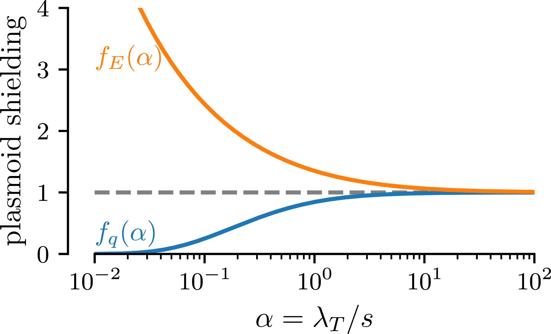


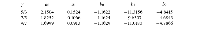

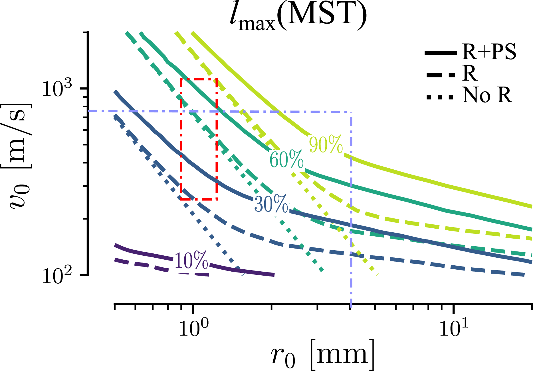


 Open access