


1. Introduction
Circular-arc ribs are frequently used for enhancing turbulent transport of momentum and thermal energy for turbine blade cooling and heat exchangers. In this class of flows, periodically spaced ribs give rise to large flow separation regions that are sensitive to not only the surface curvature of the arc but also the pitch-to-height ratio of the ribs. Turbulent motions are inhomogeneous along the streamwise and vertical directions, featuring coherent vortices with various spatial and temporal scales. These physical features greatly complicate the turbulence energy transport processes associated with eddy motions of different scales, making the characteristic length scales of the turbulence structures fundamentally different from those of a smooth-wall plane-channel flow (Kim, Moin & Moser Reference Kim, Moin and Moser1987; Hoyas & Jiménez Reference Hoyas and Jiménez2006). The presence of transverse ribs typically triggers a strong internal shear layer (ISL) around the rib height and induces a large separation bubble on the lee of a rib (Leonardi et al. Reference Leonardi, Orlandi, Djenidi and Antonia2004; Ikeda & Durbin Reference Ikeda and Durbin2007; MacDonald et al. Reference MacDonald, Ooi, García-Mayoral, H. and Chung2018). The ISL features strong shear stresses and large mean velocity gradients, which further lead to an enhanced turbulent-production rate and high levels of turbulence kinetic energy (TKE). The presence of ISL is a characteristic of turbulent flows over a ribbed surface, and a thorough understanding of the energy transport processes across the ISL is critical for understanding the rib effects on the flow dynamics and structures.
1.1. Rib effects on turbulent motions
Turbulent flows over ribs have been investigated intensively through experimental and numerical studies in the current literature. For instance, Djenidi, Elavarasan & Antonia (Reference Djenidi, Elavarasan and Antonia1999) measured a turbulent boundary-layer flow over transverse square bars and cavities using laser-induced fluorescence (LIF) and a laser Doppler velocimeter (LDV), and observed a local maximum of Reynolds shear stress near the rib height. Volino et al. (Reference Volino, Schultz and Flack2007, Reference Volino, Schultz and Flack2009) conducted water-channel experiments to compare zero-pressure-gradient (ZPG) boundary-layer flows over flat plates roughened with a wire mesh or transverse square bars using a LDV. They found that the characteristic scales of turbulence structures induced by transverse square bars were much larger than those induced by a wire mesh. Leonardi et al. (Reference Leonardi, Orlandi, Djenidi and Antonia2004) conducted direct numerical simulations (DNS) of a fully developed two-dimensional (2-D) turbulent channel flow over transverse square ribs mounted on one wall. They concluded that the coherency of streaky structures became decreased in the streamwise direction at a high pitch-to-height ratio as a result of flow ejections from cavities. Burattini et al. (Reference Burattini, Leonardi, Orlandi and Antonia2008) investigated turbulent channel flows over transverse square ribs using both hot-wire anemometers and DNS, and observed that the profiles of Reynolds normal stresses on the ribbed-wall side were almost independent of the Reynolds number when scaled by the outer coordinate of a turbulent boundary layer. Leonardi et al. (Reference Leonardi, Orlandi, Djenidi and Antonia2015) conducted DNS of a turbulent channel flow with square bars placed on one wall. By examining the spatial two-point auto-correlations of velocity fluctuations, they observed that the maximum streamwise scale of turbulence structures was 2.5 times the rib height. Lee, Kim & Lee (Reference Lee, Kim and Lee2016) conducted DNS of a turbulent boundary layer over square ribs, and observed that adjacent long flow structures often combined to form a longer structure through a spanwise merging process near the ribbed wall.
1.2. Physical analysis of TKE transport processes in rib-roughened flows
Owing to the disturbances from the ribs, turbulent flows become highly anisotropic in the separation and reattachment regions, which significantly complicates the transport process of TKE and leads to a great challenge for turbulence modelling of such flows. Accordingly, there are many reported experimental and numerical investigations into the transport equations of Reynolds stresses of turbulent flows over ribs, well presented by the works of Hirota, Ykosawa & Fujita (Reference Hirota, Ykosawa and Fujita1992), Nagano, Hattori & Houra (Reference Nagano, Hattori and Houra2004), Ikeda & Durbin (Reference Ikeda and Durbin2007) and Burattini et al. (Reference Burattini, Leonardi, Orlandi and Antonia2008). For instance, Nagano et al. (Reference Nagano, Hattori and Houra2004) conducted DNS of turbulent channel flows over transverse rectangular ribs. Based on an analysis of the budget balance of TKE, they observed that the turbulence production was trivial in the inter-rib region between two adjacent ribs where the TKE was maintained primarily by the turbulent-diffusion term. Ikeda & Durbin (Reference Ikeda and Durbin2007) performed DNS of turbulent channel flows with transverse square ribs placed on one wall, and observed a strong turbulence production rate of TKE slightly above the rib crest.
Clearly, the complex turbulence energy transport process under the rib effects involves energetic eddies of various characteristic length scales, which are also sensitive to the flow and geometry parameters such as the Reynolds number, blockage ratio and pitch-to-height ratio. It should be indicated that the previous studies of the budget balance of the transport equations of TKE and Reynolds stresses in ribbed channel or duct flows reviewed were conducted exclusively in the physical space. To develop a deeper understanding of the problem, the TKE transport process associated with turbulent motions of varying length scales can be further studied through the transport equation of Reynolds stresses in the spectral space, which is useful for precisely identifying the characteristic length scales of turbulence structures and understanding the TKE cascade across wavelengths.
1.3. Spectral analysis of TKE transport processes in smooth-wall flows
In his pioneering work, Lumley (Reference Lumley1964) derived the spectral energy equation to study the budget balance of TKE in the spectral space in the context of wall turbulence. Aulery et al. (Reference Aulery, Toutant, Bataille and Zhou2015, Reference Aulery, Dupuy, Toutant, Bataille and Zhou2017) performed spectral analysis of the TKE transport process in plane-channel flows, and observed the inverse energy cascade of TKE to turbulent motions with characteristic scales larger than the channel height. Mizuno (Reference Mizuno2016) conducted DNS of a plane-channel flow to study the transport of TKE in the spectral space, and observed that the dominant structures of different wavelengths were self-similar in the energy transport process. Lee & Moser (Reference Lee and Moser2019) conducted a spectral analysis of the budget balance of Reynolds stresses using DNS data of turbulent plane-channel flows, and observed that the large-scale streamwise-elongated flow structures played a significant role in the energy transport process. It should be indicated that the spectral studies of TKE transport processes have been limited to boundary-layer flows developing over smooth walls of simple domain geometry such as turbulent plane-channel flows. Spectral analysis of turbulent transport of TKE and Reynolds stresses in the context of ribbed-channel flows is still absent in the current literature.
1.4. Objectives
Notwithstanding the contributions of the remarkable works reviewed, it is noted that the number of studies on spectral analysis of turbulent energy transport processes is still relatively limited in the current literature, focusing exclusively on DNS of smooth-wall flows (Mizuno Reference Mizuno2016; Lee & Moser Reference Lee and Moser2019; Yang et al. Reference Yang, Deng, Wang and Shen2020) over the recent decade. Thus far, no high-fidelity DNS study on transport of Reynolds stresses and TKE in the spectral space has been reported in the context of a ribbed boundary-layer flow. In view of this knowledge gap, we aim at performing a comprehensive spectral analysis of the budget balance of the TKE transport equation based on high-fidelity DNS data of turbulent channel flows with circular-arc ribs mounted on one wall. This study focuses on the rib effects on the characteristic scales of the turbulent motions and structures. The present study is also a natural extension of our recent work (Xiong et al. Reference Xiong, Xu, Wang and Mahmoodi-Jezeh2023) from a physical-space study to a spectral-space study on the turbulent flows in ribbed channels.
The remainder of this paper is organised as follows. In § 2, the test cases and numerical algorithm for performing DNS are introduced. Grid resolutions are also described in this section. In § 3, the main flow patterns are demonstrated and analysed briefly to present an overview of the physical features of this type of ribbed-channel flow. In § 4, the rib effects on the characteristic spanwise scales of turbulent structures are studied using the two-point auto-correlation coefficients and premultiplied energy spectra of TKE. In § 5, the energy transport processes of TKE at different spanwise scales are examined in detail through investigations into the distributions of the premultiplied budget terms of TKE in both physical and spectral spaces. In § 6, major findings and conclusions of this research are summarised.
2. Test cases and numerical algorithm
Figure 1 shows the schematic diagram of the computational domain of the ribbed channel and the coordinate system. Here, $x$
,
$x$
, $y$
and
$y$
and $z$
denote the streamwise, vertical and spanwise coordinates, respectively. The flow goes through the channel bounded by a top smooth wall and a bottom ribbed wall. The streamwise and spanwise domain sizes are set to
$z$
denote the streamwise, vertical and spanwise coordinates, respectively. The flow goes through the channel bounded by a top smooth wall and a bottom ribbed wall. The streamwise and spanwise domain sizes are set to $L_x=12\delta$
and
$L_x=12\delta$
and $L_z=2\pi \delta$
, respectively, where
$L_z=2\pi \delta$
, respectively, where $\delta =L_y/2$
is the half-channel height. The pitch and height of the circular-arc ribs are
$\delta =L_y/2$
is the half-channel height. The pitch and height of the circular-arc ribs are $P$
and
$P$
and $H$
, respectively.
$H$
, respectively.
Schematic diagram of the computational domain and coordinate system. The origin of the absolute coordinate system $[x,y,z]$
is located at the inner bottom corner of the inlet, and the origin of the relative streamwise coordinate
$[x,y,z]$
is located at the inner bottom corner of the inlet, and the origin of the relative streamwise coordinate $x'$
is located at the windward face of each rib, which is defined to facilitate the analysis within a rib period.
$x'$
is located at the windward face of each rib, which is defined to facilitate the analysis within a rib period.

Four test cases (P1, P2, P3 and P3R) of ribbed-channel flows and two smooth-channel-flow cases (SC and SCR) are considered in our comparative study. The design of these six test cases is not arbitrary, which facilitates a comparative study of rib effects on the flow field under the influences of two parameters, i.e. the pitch-to-height ratio ( $P/H$
) and Reynolds number. In the four ribbed-channel-flow cases, the radius of the rib arc is kept constant, i.e.
$P/H$
) and Reynolds number. In the four ribbed-channel-flow cases, the radius of the rib arc is kept constant, i.e. $R=H=0.2\delta$
. Cases P1, P2 and P3 are compared to investigate the effects of the pitch-to-height ratio (of
$R=H=0.2\delta$
. Cases P1, P2 and P3 are compared to investigate the effects of the pitch-to-height ratio (of $P/H=3.0$
, 5.0 and 7.5, respectively) on the flow field based on a common blockage ratio of
$P/H=3.0$
, 5.0 and 7.5, respectively) on the flow field based on a common blockage ratio of ${\textit{Br}}=H/2\delta =0.1$
. The nominal Reynolds number is fixed at
${\textit{Br}}=H/2\delta =0.1$
. The nominal Reynolds number is fixed at ${\textit{Re}}_{b,N}=2\delta U_b/\nu =5600$
in cases P1, P2 and P3 to maintain a constant mass flow rate, where
${\textit{Re}}_{b,N}=2\delta U_b/\nu =5600$
in cases P1, P2 and P3 to maintain a constant mass flow rate, where $U_b$
denotes the bulk mean streamwise velocity at the inlet of the channel and
$U_b$
denotes the bulk mean streamwise velocity at the inlet of the channel and $\nu$
denotes the kinematic viscosity of the fluid. In addition, the Reynolds number effect on the ribbed turbulent channel flow is examined by including case P3R, which shares the same geometry as case P3, but has a moderately high nominal Reynolds number of
$\nu$
denotes the kinematic viscosity of the fluid. In addition, the Reynolds number effect on the ribbed turbulent channel flow is examined by including case P3R, which shares the same geometry as case P3, but has a moderately high nominal Reynolds number of ${\textit{Re}}_{b,N}=14\,600$
. Given the fixed domain size, cases P1, P2, P3 and P3R consist of 20, 12, 8 and 8 periods, respectively. In order to identify the rib effects, two additional cases of smooth-channel flows of different nominal Reynolds numbers (
${\textit{Re}}_{b,N}=14\,600$
. Given the fixed domain size, cases P1, P2, P3 and P3R consist of 20, 12, 8 and 8 periods, respectively. In order to identify the rib effects, two additional cases of smooth-channel flows of different nominal Reynolds numbers ( ${\textit{Re}}_{b,N}=5600$
for case SC and 14 600 for case SCR) have been considered. The choice of the lower Reynolds number of
${\textit{Re}}_{b,N}=5600$
for case SC and 14 600 for case SCR) have been considered. The choice of the lower Reynolds number of ${\textit{Re}}_{b,N}=5600$
follows the classical work of Kim et al. (Reference Kim, Moin and Moser1987), who pioneered the DNS study of turbulent plane-channel flows. The flow field is fully developed, and periodic boundary conditions are applied in the streamwise and spanwise directions. A no-slip boundary condition is imposed on all solid surfaces.
${\textit{Re}}_{b,N}=5600$
follows the classical work of Kim et al. (Reference Kim, Moin and Moser1987), who pioneered the DNS study of turbulent plane-channel flows. The flow field is fully developed, and periodic boundary conditions are applied in the streamwise and spanwise directions. A no-slip boundary condition is imposed on all solid surfaces.
The continuity and momentum equations that govern the motion of an incompressible flow are written as
 \begin{align} \frac {\partial u_i}{\partial x_i}&=0 , \end{align}
 \begin{align} \frac {\partial u_i}{\partial t}+u_{\!j}\frac {\partial u_i}{\partial x_{\!j}}&=-\frac {1}{\rho }\delta _{1i}\varPi -\frac {1}{\rho }\frac {\partial p}{\partial x_i}+\nu \frac {\partial ^2u_i}{{\partial x_{\!j}}{\partial x_{\!j}}} , \end{align}
where $u_i$
,
$u_i$
, $\rho$
,
$\rho$
, $p$
and
$p$
and $\delta _{\textit{ij}}$
represent the velocity, density, pressure, and Kronecker delta, respectively. In addition,
$\delta _{\textit{ij}}$
represent the velocity, density, pressure, and Kronecker delta, respectively. In addition, $\varPi$
is an imposed constant mean streamwise pressure gradient that drives the flow. Tensor notation is used in governing equations (2.1) and (2.2) with which the streamwise, vertical and spanwise coordinates are denoted as
$\varPi$
is an imposed constant mean streamwise pressure gradient that drives the flow. Tensor notation is used in governing equations (2.1) and (2.2) with which the streamwise, vertical and spanwise coordinates are denoted as $x_i$
for
$x_i$
for $i=1$
, 2 and 3, respectively. Correspondingly, the velocity components
$i=1$
, 2 and 3, respectively. Correspondingly, the velocity components $u$
,
$u$
, $v$
and
$v$
and $w$
are denoted using
$w$
are denoted using $u_1$
,
$u_1$
, $u_2$
and
$u_2$
and $u_3$
, respectively. To make it convenient for statistical analysis of the flow field within a repeated rib period, a relative streamwise coordinate
$u_3$
, respectively. To make it convenient for statistical analysis of the flow field within a repeated rib period, a relative streamwise coordinate $x'$
is defined with its origin located at the windward corner of each rib as shown in figure 1.
$x'$
is defined with its origin located at the windward corner of each rib as shown in figure 1.
The DNS is performed using a spectral-element code so-called ‘Semtex’ contributed by Blackburn & Sherwin (Reference Blackburn and Sherwin2004). This code is developed using C++ and FORTRAN programming languages, and parallelised using message passing interface (MPI) libraries. A second-order time-splitting scheme with three substeps developed by Karniadakis, Israeli & Orszag (Reference Karniadakis, Israeli and Orszag1991) is used for time integration. Specifically, an intermediate velocity is obtained in the first substep by advancing the convection and body-force ( $\varPi$
) terms using a second-order backward time-differencing scheme. Subsequently, the intermediate velocity is used in the second time substep to determine the pressure field in order to satisfy the continuity equation. In the third substep, the viscous term of the momentum equation is implicitly integrated with the prescribed boundary conditions. The last two time substeps rely on solving the 2-D Helmholtz equations in the spectral space based on a static condensation technique introduced by Karniadakis & Sherwin (Reference Karniadakis and Sherwin2005).
$\varPi$
) terms using a second-order backward time-differencing scheme. Subsequently, the intermediate velocity is used in the second time substep to determine the pressure field in order to satisfy the continuity equation. In the third substep, the viscous term of the momentum equation is implicitly integrated with the prescribed boundary conditions. The last two time substeps rely on solving the 2-D Helmholtz equations in the spectral space based on a static condensation technique introduced by Karniadakis & Sherwin (Reference Karniadakis and Sherwin2005).
Quadrilateral spectral-elements are used for discretisation in the streamwise and vertical directions. The mesh for the finite-element nodes was determined by solving an elliptic partial differential equation following the approach of Thompson, Frank & Mastin (Reference Thompson, Frank and Mastin1977). In each finite element in the $x$
-
$x$
- $y$
plane, a fourth-order Gauss–Lobatto–Legendre Lagrange (GLLL) polynomial was used for further interpolation of flow variables. To demonstrate, figure 2 shows a partial mesh used for performing DNS of case P3. Given that the GLLL polynomial interpolants are non-uniform within each finite element, the mesh is non-uniform in figure 2. Further using case P3 as the example, there are 15 360 (
$y$
plane, a fourth-order Gauss–Lobatto–Legendre Lagrange (GLLL) polynomial was used for further interpolation of flow variables. To demonstrate, figure 2 shows a partial mesh used for performing DNS of case P3. Given that the GLLL polynomial interpolants are non-uniform within each finite element, the mesh is non-uniform in figure 2. Further using case P3 as the example, there are 15 360 ( $384\times40$
) quadrilateral-structural elements over the
$384\times40$
) quadrilateral-structural elements over the $x$
-
$x$
- $y$
plane. In each finite element, there are
$y$
plane. In each finite element, there are $5\times 5$
GLLL points, and so there are 247 457 (i.e.
$5\times 5$
GLLL points, and so there are 247 457 (i.e. $N_x\times N_y=1537\times 161$
) GLLL points in the
$N_x\times N_y=1537\times 161$
) GLLL points in the $x$
-
$x$
- $y$
plane (overlapped points on the shared edges of adjacent elements are excluded). In the spanwise (
$y$
plane (overlapped points on the shared edges of adjacent elements are excluded). In the spanwise ( $z$
) direction, all physical quantities are expanded into Fourier series in the spectral space. In total, the number of Fourier modes
$z$
) direction, all physical quantities are expanded into Fourier series in the spectral space. In total, the number of Fourier modes $N_z$
used is 160 in case SC, 240 in cases P1, P2 and P3, 320 in case SCR, and 512 in case P3R. Table 1 summarises the grid resolutions of all six test cases, where
$N_z$
used is 160 in case SC, 240 in cases P1, P2 and P3, 320 in case SCR, and 512 in case P3R. Table 1 summarises the grid resolutions of all six test cases, where $(\boldsymbol{\cdot })_s^+$
is a quantity scaled by wall units based on the friction velocity of the top smooth wall
$(\boldsymbol{\cdot })_s^+$
is a quantity scaled by wall units based on the friction velocity of the top smooth wall $u_{\tau S}$
. The mesh is refined near all solid surfaces. As seen in table 1, for the four ribbed test cases, the grid resolutions along the streamwise, vertical and spanwise directions vary within
$u_{\tau S}$
. The mesh is refined near all solid surfaces. As seen in table 1, for the four ribbed test cases, the grid resolutions along the streamwise, vertical and spanwise directions vary within $0.62\leqslant (\Delta x)^+_s\leqslant 5.15$
,
$0.62\leqslant (\Delta x)^+_s\leqslant 5.15$
, $0.16\leqslant (\Delta y)^+_s\leqslant 6.47$
and
$0.16\leqslant (\Delta y)^+_s\leqslant 6.47$
and $5.46\leqslant (\Delta z)^+_s\leqslant 6.47$
, respectively. For the two smooth-channel-flow cases, the grid resolutions are similar to those used by Moser, Kim & Mansour (Reference Moser, Kim and Mansour1999). To satisfy the demanding requirement of DNS on grid resolutions, the ratio of the grid size over the Kolmogorov scale
$5.46\leqslant (\Delta z)^+_s\leqslant 6.47$
, respectively. For the two smooth-channel-flow cases, the grid resolutions are similar to those used by Moser, Kim & Mansour (Reference Moser, Kim and Mansour1999). To satisfy the demanding requirement of DNS on grid resolutions, the ratio of the grid size over the Kolmogorov scale $\eta$
is given in table 1, which varies within range
$\eta$
is given in table 1, which varies within range $0.08\leqslant \varDelta /\eta \leqslant 3.97$
in all six test cases. Here, the averaged grid size
$0.08\leqslant \varDelta /\eta \leqslant 3.97$
in all six test cases. Here, the averaged grid size $\varDelta$
and Kolmogorov length scale
$\varDelta$
and Kolmogorov length scale $\eta$
are calculated as
$\eta$
are calculated as $\varDelta =\sqrt [3]{\varDelta _x\varDelta _y\varDelta _z}$
and
$\varDelta =\sqrt [3]{\varDelta _x\varDelta _y\varDelta _z}$
and $\eta = (\nu ^3/\varepsilon _k)^{1/4}$
, respectively, and
$\eta = (\nu ^3/\varepsilon _k)^{1/4}$
, respectively, and $\varepsilon _k$
is the local dissipation rate defined as
$\varepsilon _k$
is the local dissipation rate defined as $\varepsilon _k=\nu \langle ({\partial u^{\prime}_i}/{\partial x_{\!j}})({\partial u^{\prime}_i}/{\partial x_{\!j}})\rangle$
. Symbol
$\varepsilon _k=\nu \langle ({\partial u^{\prime}_i}/{\partial x_{\!j}})({\partial u^{\prime}_i}/{\partial x_{\!j}})\rangle$
. Symbol $\langle\cdot\rangle$
denotes averaging over time and the homogeneous spanwise direction, and, additionally, over all rib periods (in the ribbed-channel-flow cases) or over the homogeneous streamwise direction (in the smooth-channel-flow cases). In turbulence decomposition,
$\langle\cdot\rangle$
denotes averaging over time and the homogeneous spanwise direction, and, additionally, over all rib periods (in the ribbed-channel-flow cases) or over the homogeneous streamwise direction (in the smooth-channel-flow cases). In turbulence decomposition, $(\cdot)'$
denotes an instantaneous fluctuation with respect to the averaged value, i.e.
$(\cdot)'$
denotes an instantaneous fluctuation with respect to the averaged value, i.e. $(\cdot)'=(\cdot)-\langle\cdot\rangle$
. Overall, the discrete solution to the governing equations based on the Semtex code is highly accurate, and the DNS results are of a spectral accuracy. The computer code has been used by our group for conducting DNS studies of rotating elliptical pipe flows (Rosas, Zhang & Wang Reference Rosas, Zhang and Wang2021), rotating and non-rotating circular pipe flows (Zhang & Wang Reference Zhang and Wang2019, Reference Zhang and Wang2024), spanwise-rotating turbulent square duct flows (Fang et al. Reference Fang, Yang, Wang and Bergstrom2017), and turbulent channel flow and heat convection with circular-arc ribs mounted on one wall (Xiong et al. Reference Xiong, Xu, Wang and Mahmoodi-Jezeh2023, Reference Xiong, Xu, Wang and Mahmoodi-Jezeh2024).
$(\cdot)'=(\cdot)-\langle\cdot\rangle$
. Overall, the discrete solution to the governing equations based on the Semtex code is highly accurate, and the DNS results are of a spectral accuracy. The computer code has been used by our group for conducting DNS studies of rotating elliptical pipe flows (Rosas, Zhang & Wang Reference Rosas, Zhang and Wang2021), rotating and non-rotating circular pipe flows (Zhang & Wang Reference Zhang and Wang2019, Reference Zhang and Wang2024), spanwise-rotating turbulent square duct flows (Fang et al. Reference Fang, Yang, Wang and Bergstrom2017), and turbulent channel flow and heat convection with circular-arc ribs mounted on one wall (Xiong et al. Reference Xiong, Xu, Wang and Mahmoodi-Jezeh2023, Reference Xiong, Xu, Wang and Mahmoodi-Jezeh2024).
Partial mesh of finite elements for case P3 in a streamwise-vertical ( $x$
-
$x$
- $y$
) plane. For clarity, only two rib periods of the mesh are shown. Over the entire
$y$
) plane. For clarity, only two rib periods of the mesh are shown. Over the entire $x$
-
$x$
- $y$
plane, there are 15 360 finite elements with each element further discretised using a 4th-order GLLL polynomial (shown as blue mesh in the inset). In the spanwise (
$y$
plane, there are 15 360 finite elements with each element further discretised using a 4th-order GLLL polynomial (shown as blue mesh in the inset). In the spanwise ( $z$
) direction (not shown), Fourier expansion of 240 modes is used for spatial discretisation.
$z$
) direction (not shown), Fourier expansion of 240 modes is used for spatial discretisation.

Summary of six test cases and grid resolutions. The wall units are defined based on the friction velocity of the top smooth wall $u_{\tau S}$
.
$u_{\tau S}$
.

For each simulated case, 600 instantaneous flow fields over 35 large-eddy turnover times (LETOTs, defined as $\delta /u_{\tau R}$
) were used for collecting statistics once the flow became fully developed and statistically stationary after a precursor simulation. Here,
$\delta /u_{\tau R}$
) were used for collecting statistics once the flow became fully developed and statistically stationary after a precursor simulation. Here, $u_{\tau R}$
denotes the average friction velocity over the bottom ribbed wall. The simulations were conducted using the GREX supercomputers located at the University of Manitoba, Canada. Approximately 20 TB of data have been generated for the six simulated cases. For each test case of the ribbed-channel flow, approximately
$u_{\tau R}$
denotes the average friction velocity over the bottom ribbed wall. The simulations were conducted using the GREX supercomputers located at the University of Manitoba, Canada. Approximately 20 TB of data have been generated for the six simulated cases. For each test case of the ribbed-channel flow, approximately $20\,0000$
CPU hours were spent for solving the velocity field and for collecting the flow statistics.
$20\,0000$
CPU hours were spent for solving the velocity field and for collecting the flow statistics.
3. Key characteristics and parameters of the flow
In this section, key features of turbulent channel flows over circular-arc ribs are described briefly in the physical space, which are fundamental for the follow-up spectral analysis of turbulent motions and energy transport processes. The mean flow structures of the four ribbed cases are shown in figure 3 based on the streamlines and contours of TKE (defined as $k=\langle u_i^{\prime}u_i^{\prime}\rangle /2$
) non-dimensionalised by
$k=\langle u_i^{\prime}u_i^{\prime}\rangle /2$
) non-dimensionalised by $U_b^2$
. Strictly speaking, the relative streamwise coordinate resets (
$U_b^2$
. Strictly speaking, the relative streamwise coordinate resets ( $x'= 0$
) at the windward corner of each rib, and reaches its maximum value of
$x'= 0$
) at the windward corner of each rib, and reaches its maximum value of $x'= P$
at the windward corner of the next (downstream) rib. To facilitate a direct comparison of the mean flow patterns of the four different ribbed-channel-flow cases over the same streamwise domain length, the value of
$x'= P$
at the windward corner of the next (downstream) rib. To facilitate a direct comparison of the mean flow patterns of the four different ribbed-channel-flow cases over the same streamwise domain length, the value of $x'/\delta$
is allowed to extend continuously and scales identically in figure 3(a–d). A similar method is used for displaying the contour plots of spectral budget terms later in § 5.
$x'/\delta$
is allowed to extend continuously and scales identically in figure 3(a–d). A similar method is used for displaying the contour plots of spectral budget terms later in § 5.
Mean streamlines with contours of non-dimensional TKE $k/U_b^2$
for all four ribbed cases. Panels (a)–(d) correspond to cases P1, P2, P3 and P3R, respectively. The dot-dashed line demarcates the isopleth of
$k/U_b^2$
for all four ribbed cases. Panels (a)–(d) correspond to cases P1, P2, P3 and P3R, respectively. The dot-dashed line demarcates the isopleth of $k=0.9\max (k)$
for each case. The red dashed line demarcates the isopleth of
$k=0.9\max (k)$
for each case. The red dashed line demarcates the isopleth of $\langle u\rangle =0$
.
$\langle u\rangle =0$
.

From figure 3, it is seen that the mean flow detaches and reattaches on the circular-arc ribs. At the detachment (D) and reattachment (R) points, the local mean wall shear stress vanishes . In the four ribbed-channel-flow cases, the streamwise position of the detachment point D occurs on the rib leeward surface at $x'\!_D/\delta =0.278$
, 0.276, 0.263 and 0.251, while the reattachment point R occurs on the rib windward surface at
$x'\!_D/\delta =0.278$
, 0.276, 0.263 and 0.251, while the reattachment point R occurs on the rib windward surface at $x'\!_R/\delta =0.083$
, 0.046, 0.014 and 0.014 for cases P1, P2, P3 and P3R, respectively. The characteristic mean flow vortices are marked with A, B and C, which represent the large recirculation bubbles behind the ribs (A), and the small secondary vortices located at the corners of the leeward and windward sides of the ribs (B and C, respectively). Due to the geometric constraints, recirculation bubble A expands with an increasing value of
$x'\!_R/\delta =0.083$
, 0.046, 0.014 and 0.014 for cases P1, P2, P3 and P3R, respectively. The characteristic mean flow vortices are marked with A, B and C, which represent the large recirculation bubbles behind the ribs (A), and the small secondary vortices located at the corners of the leeward and windward sides of the ribs (B and C, respectively). Due to the geometric constraints, recirculation bubble A expands with an increasing value of $P/H$
, which leads to a reduction in the viscous friction drag on the ribbed wall (as a result of the extension of the reverse flow region). Simultaneously, the secondary corner vortices B and C tend to grow in size as the rib pitch
$P/H$
, which leads to a reduction in the viscous friction drag on the ribbed wall (as a result of the extension of the reverse flow region). Simultaneously, the secondary corner vortices B and C tend to grow in size as the rib pitch $P$
increases. According to Perry, Schofield & Joubert (Reference Perry, Schofield and Joubert1969), Bandyopadhyay (Reference Bandyopadhyay1987) and Jiménez (Reference Jiménez2004), the type of roughness of a ribbed wall typically switches from a
$P$
increases. According to Perry, Schofield & Joubert (Reference Perry, Schofield and Joubert1969), Bandyopadhyay (Reference Bandyopadhyay1987) and Jiménez (Reference Jiménez2004), the type of roughness of a ribbed wall typically switches from a $k$
- to a
$k$
- to a $d$
-type when the gap-to-height ratio becomes less than three (i.e.
$d$
-type when the gap-to-height ratio becomes less than three (i.e. $W/H\leqslant 3$
, where
$W/H\leqslant 3$
, where $W=P-2R$
is the width of the gap between two adjacent ribs). In cases P1 and P2 (
$W=P-2R$
is the width of the gap between two adjacent ribs). In cases P1 and P2 ( $W/H=1.0$
and 3.0, respectively), the mean flow skims over the ribs and the large recirculation bubble fills the whole cavity between two adjacent ribs, which is typical of a
$W/H=1.0$
and 3.0, respectively), the mean flow skims over the ribs and the large recirculation bubble fills the whole cavity between two adjacent ribs, which is typical of a $d$
-type rough-wall flow. By contrast, in cases P3 and P3R (
$d$
-type rough-wall flow. By contrast, in cases P3 and P3R ( $W/H=5.5$
), the mean flow patterns are typical of a
$W/H=5.5$
), the mean flow patterns are typical of a $k$
-type rough-wall flow, with the outermost mean streamline of recirculation bubble A (initiated from upstream rib crest) reattaching on the bottom wall at approximately
$k$
-type rough-wall flow, with the outermost mean streamline of recirculation bubble A (initiated from upstream rib crest) reattaching on the bottom wall at approximately $x'/\delta =1.25$
in the interval between two adjacent ribs.
$x'/\delta =1.25$
in the interval between two adjacent ribs.
Due to the flow separation induced by ribs, a strong ISL is generated slightly above recirculation bubble A around the rib height, featuring a strong mean velocity gradient $\partial \langle u\rangle /\partial y$
(Xiong et al. Reference Xiong, Xu, Wang and Mahmoodi-Jezeh2023). The strong shear of the mean flow is typically associated with an intensive production of TKE in turbulent flows, further leading to a high level of TKE. The contours of TKE in figure 3 show that turbulent motions are enhanced dramatically in the ISL. Specifically, for all four ribbed cases, the magnitude of TKE in the ISL can be over 90 % of its maximum at the midspan between two adjacent ribs (
$\partial \langle u\rangle /\partial y$
(Xiong et al. Reference Xiong, Xu, Wang and Mahmoodi-Jezeh2023). The strong shear of the mean flow is typically associated with an intensive production of TKE in turbulent flows, further leading to a high level of TKE. The contours of TKE in figure 3 show that turbulent motions are enhanced dramatically in the ISL. Specifically, for all four ribbed cases, the magnitude of TKE in the ISL can be over 90 % of its maximum at the midspan between two adjacent ribs ( $x'/\delta =0.5$
, 0.7, 0.95 and 0.95 for cases P1, P2, P3 and P3R, respectively). Figure 4 further compares the vertical profiles of TKE at the rib centre (
$x'/\delta =0.5$
, 0.7, 0.95 and 0.95 for cases P1, P2, P3 and P3R, respectively). Figure 4 further compares the vertical profiles of TKE at the rib centre ( $x'/\delta =0.2$
), at the rib leeward (
$x'/\delta =0.2$
), at the rib leeward ( $x'/\delta =0.4$
) and at the midspan between two adjacent ribs. As shown in figure 4, it is evident that turbulent motions near the ribbed bottom wall enhance drastically compared with those in smooth-channel flows, and the TKE magnitude increases monotonically as the value of
$x'/\delta =0.4$
) and at the midspan between two adjacent ribs. As shown in figure 4, it is evident that turbulent motions near the ribbed bottom wall enhance drastically compared with those in smooth-channel flows, and the TKE magnitude increases monotonically as the value of $P/H$
increases. From figures 3 and 4, it is interesting to observe that both the mean flow structures and profile of the non-dimensional TKE
$P/H$
increases. From figures 3 and 4, it is interesting to observe that both the mean flow structures and profile of the non-dimensional TKE $k/U_b^2$
of case P3R are qualitatively similar to those of case P3, showing an independence of
$k/U_b^2$
of case P3R are qualitatively similar to those of case P3, showing an independence of ${\textit{Re}}_b$
which is consistent with the observation of Burattini et al. (Reference Burattini, Leonardi, Orlandi and Antonia2008) in their DNS study of turbulent plane-channel flows with transverse square ribs placed on one wall. Among these three streamwise positions, it is apparent that TKE reaches its highest level at the midspan between two adjacent ribs in all four ribbed cases. In view of this, in the remainder of our analysis, we pay close attention to this special streamwise position (
${\textit{Re}}_b$
which is consistent with the observation of Burattini et al. (Reference Burattini, Leonardi, Orlandi and Antonia2008) in their DNS study of turbulent plane-channel flows with transverse square ribs placed on one wall. Among these three streamwise positions, it is apparent that TKE reaches its highest level at the midspan between two adjacent ribs in all four ribbed cases. In view of this, in the remainder of our analysis, we pay close attention to this special streamwise position ( $x'/\delta =0.5$
, 0.7, 0.95 and 0.95 for cases P1, P2, P3 and P3R, respectively) in our investigation into the characteristics of the most energetic turbulence structures.
$x'/\delta =0.5$
, 0.7, 0.95 and 0.95 for cases P1, P2, P3 and P3R, respectively) in our investigation into the characteristics of the most energetic turbulence structures.
Vertical profiles of non-dimensional TKE at the rib centre ( $x'/\delta =0.2$
), the rib leeward corner (
$x'/\delta =0.2$
), the rib leeward corner ( $x'/\delta =0.4$
) and the midspan between two adjacent ribs (
$x'/\delta =0.4$
) and the midspan between two adjacent ribs ( $x'/\delta =0.5$
, 0.7, 0.95 and 0.95 for cases P1, P2, P3 and P3R, respectively). The vertical pink dashed line demarcates the rib top.
$x'/\delta =0.5$
, 0.7, 0.95 and 0.95 for cases P1, P2, P3 and P3R, respectively). The vertical pink dashed line demarcates the rib top.

Figure 5 further compares the vertical profiles of three normal components of the Reynolds stress tensor at the midspan between two adjacent ribs. As shown in figure 5, the dominance of $\langle u'u'\rangle$
among these three normal stress components is evident in both smooth and ribbed flows. For the smooth-channel flow, the peak of
$\langle u'u'\rangle$
among these three normal stress components is evident in both smooth and ribbed flows. For the smooth-channel flow, the peak of $\langle u'u'\rangle$
occurs approximately at
$\langle u'u'\rangle$
occurs approximately at $y^+=15$
(or at
$y^+=15$
(or at $y/\delta =0.079$
and 0.036 for cases SC and SCR, respectively) in the near-wall region. However, with the presence of ribs, all components of Reynolds normal stresses increase dramatically (monotonically as the value of
$y/\delta =0.079$
and 0.036 for cases SC and SCR, respectively) in the near-wall region. However, with the presence of ribs, all components of Reynolds normal stresses increase dramatically (monotonically as the value of $P/H$
increases), and reach their maxima in the ISL around the rib height. Specifically, the peak value of
$P/H$
increases), and reach their maxima in the ISL around the rib height. Specifically, the peak value of $\langle u'u'\rangle$
is located at
$\langle u'u'\rangle$
is located at $y/\delta =0.23$
in all four ribbed cases, slightly above the rib crest, while the peaks of
$y/\delta =0.23$
in all four ribbed cases, slightly above the rib crest, while the peaks of $\langle v'v'\rangle$
and
$\langle v'v'\rangle$
and $\langle w'w'\rangle$
move downwards as the value of
$\langle w'w'\rangle$
move downwards as the value of $P/H$
increases.
$P/H$
increases.
Vertical profiles of non-dimensional Reynolds normal stresses at the midspan between two adjacent ribs ( $x'/\delta =0.5$
, 0.7, 0.95 and 0.95 for cases P1, P2, P3 and P3R, respectively). Arrow points to the direction of an increasing value of
$x'/\delta =0.5$
, 0.7, 0.95 and 0.95 for cases P1, P2, P3 and P3R, respectively). Arrow points to the direction of an increasing value of $P/H$
for cases of
$P/H$
for cases of ${\textit{Re}}_{b,N}=5600$
. The vertical pink dashed line demarcates the rib top.
${\textit{Re}}_{b,N}=5600$
. The vertical pink dashed line demarcates the rib top.

Table 2 summarises the key flow parameters of the six test cases. Here, two friction Reynolds numbers ( ${\textit{Re}}_{\tau R}=\delta u_{\tau R}/\nu$
and
${\textit{Re}}_{\tau R}=\delta u_{\tau R}/\nu$
and ${\textit{Re}}_{\tau S}=\delta u_{\tau S}/\nu$
) are defined based on the mean streamwise wall friction velocities on the ribbed bottom wall (
${\textit{Re}}_{\tau S}=\delta u_{\tau S}/\nu$
) are defined based on the mean streamwise wall friction velocities on the ribbed bottom wall ( $u_{\tau R}$
) and smooth top wall (
$u_{\tau R}$
) and smooth top wall ( $u_{\tau S}$
), respectively. In the simulations, the value of the mean streamwise pressure gradient
$u_{\tau S}$
), respectively. In the simulations, the value of the mean streamwise pressure gradient $\varPi$
of (2.2) was carefully adjusted through test runs to ensure that the bulk Reynolds number calculated from DNS converged to its nominal value of either
$\varPi$
of (2.2) was carefully adjusted through test runs to ensure that the bulk Reynolds number calculated from DNS converged to its nominal value of either ${\textit{Re}}_{b,N}=5600$
or 14 600. The method for calculating the values of friction velocities follows the approaches of Napoli, Armenio & De Marchis (Reference Napoli, Armenio and De Marchis2008), Xiong et al. (Reference Xiong, Xu, Wang and Mahmoodi-Jezeh2023) and Opperman, Xiong & Wang (Reference Opperman, Xiong and Wang2025), viz.
${\textit{Re}}_{b,N}=5600$
or 14 600. The method for calculating the values of friction velocities follows the approaches of Napoli, Armenio & De Marchis (Reference Napoli, Armenio and De Marchis2008), Xiong et al. (Reference Xiong, Xu, Wang and Mahmoodi-Jezeh2023) and Opperman, Xiong & Wang (Reference Opperman, Xiong and Wang2025), viz. $ u^2_{\tau R} = (D_{\textit{pR}} +D_{\nu R})/\rho$
and
$ u^2_{\tau R} = (D_{\textit{pR}} +D_{\nu R})/\rho$
and $u^2_{\tau S} = D_{\nu S}/\rho$
. Here,
$u^2_{\tau S} = D_{\nu S}/\rho$
. Here, $D_{\textit{pR}}$
,
$D_{\textit{pR}}$
, $D_{\nu R}$
and
$D_{\nu R}$
and $D_{\nu S}$
are the mean pressure and viscous drags per unit area on the ribbed wall, and the mean viscous drag per unit area on the smooth wall, respectively, determined as
$D_{\nu S}$
are the mean pressure and viscous drags per unit area on the ribbed wall, and the mean viscous drag per unit area on the smooth wall, respectively, determined as
 \begin{align} D_{\textit{pR}} &= \frac {1}{ L_x}\int _{R}\langle p\rangle \mathrm{d}y, \end{align}
 \begin{align} D_{\nu R} &= \frac {\mu }{L_x}\int _{R}\left [\left (\frac {\partial \langle u\rangle }{\partial y}+\frac {\partial \langle v\rangle }{\partial x}\right ) \mathrm{d}x-2\frac {\partial \langle u \rangle }{\partial x} \mathrm{d}y\right ]\!, \end{align}
and
 \begin{equation} D_{\nu S} = \frac {\mu }{L_x}\int _{S}\left (\frac {\partial \langle u\rangle }{\partial y}+\frac {\partial \langle v\rangle }{\partial x}\right ) \mathrm{d}x, \end{equation}
where $\mu=\rho\nu$
is the dynamic viscosity of the fluid, and subscripts ‘
$\mu=\rho\nu$
is the dynamic viscosity of the fluid, and subscripts ‘ $R$
’ and ‘
$R$
’ and ‘ $S$
’ indicate the integration of local wall values over the curved ribbed bottom and smooth top walls, respectively.
$S$
’ indicate the integration of local wall values over the curved ribbed bottom and smooth top walls, respectively.
Key parameters of the mean flow fields of the six test cases. Here, $C_{d0}$
denotes the drag coefficient of a smooth turbulent plane-channel flow at
$C_{d0}$
denotes the drag coefficient of a smooth turbulent plane-channel flow at ${\textit{Re}}_{b,N}=5600$
(for cases P1, P2, P3 and SC) or at
${\textit{Re}}_{b,N}=5600$
(for cases P1, P2, P3 and SC) or at ${\textit{Re}}_{b,N}=14\,600$
(for cases P3R and SCR).
${\textit{Re}}_{b,N}=14\,600$
(for cases P3R and SCR).

The pressure and viscous drag coefficients on the ribbed wall are defined as $C_{dR,p} = D_{\textit{pR}}/( \rho U_b^2/2)$
and
$C_{dR,p} = D_{\textit{pR}}/( \rho U_b^2/2)$
and $C_{dR,\nu } = D_{\nu R}/(\rho U_b^2/2)$
, respectively. Similarly,
$C_{dR,\nu } = D_{\nu R}/(\rho U_b^2/2)$
, respectively. Similarly, $C_{dS}=D_{\nu S}/(\rho U_b^2/2)$
is the drag coefficient on the smooth wall. In addition, the total drag coefficient of the ribbed channel is calculated by
$C_{dS}=D_{\nu S}/(\rho U_b^2/2)$
is the drag coefficient on the smooth wall. In addition, the total drag coefficient of the ribbed channel is calculated by $C_{d}=(C_{dR,p}+C_{dR,\nu }+C_{dS})/2$
. Table 2 clearly shows that in the presence of the ribs, the drag augments drastically compared with that in a smooth channel, and the drag coefficient
$C_{d}=(C_{dR,p}+C_{dR,\nu }+C_{dS})/2$
. Table 2 clearly shows that in the presence of the ribs, the drag augments drastically compared with that in a smooth channel, and the drag coefficient $C_d$
increases monotonically with an increasing value of
$C_d$
increases monotonically with an increasing value of $P/H$
. By comparing cases P3 and P3R, it is seen that as the Reynolds number increases, the drag coefficient decreases in both ribbed- and smooth-channel flows; however, the ratio
$P/H$
. By comparing cases P3 and P3R, it is seen that as the Reynolds number increases, the drag coefficient decreases in both ribbed- and smooth-channel flows; however, the ratio $C_d/C_{d0}$
increases from 3.385 to 3.986. Here,
$C_d/C_{d0}$
increases from 3.385 to 3.986. Here, $C_{d0}$
denotes the total drag coefficient of a smooth turbulent plane-channel flow of the corresponding Reynolds number (i.e.
$C_{d0}$
denotes the total drag coefficient of a smooth turbulent plane-channel flow of the corresponding Reynolds number (i.e. $C_{d0}=C_{dS}$
for case SC or SCR). It is clear that as the value of
$C_{d0}=C_{dS}$
for case SC or SCR). It is clear that as the value of $P/H$
increases, the drag on both top and bottom walls increases. Accordingly, both values of
$P/H$
increases, the drag on both top and bottom walls increases. Accordingly, both values of ${\textit{Re}}_{\tau R}$
and
${\textit{Re}}_{\tau R}$
and ${\textit{Re}}_{\tau S}$
increase as the value of
${\textit{Re}}_{\tau S}$
increase as the value of $P/H$
increases. By comparing the values of
$P/H$
increases. By comparing the values of $C_{dR,p}$
,
$C_{dR,p}$
, $C_{dR,\nu }$
and
$C_{dR,\nu }$
and $C_{dS}$
listed in table 2, it is evident that the pressure drag contributes the most to the total drag in all four ribbed channels due to the large boundary-layer separation regions induced by ribs. As the value of
$C_{dS}$
listed in table 2, it is evident that the pressure drag contributes the most to the total drag in all four ribbed channels due to the large boundary-layer separation regions induced by ribs. As the value of $P/H$
increases (from case P1 to P3), the pressure drag becomes increasingly predominant and the viscous drag on the ribbed walls becomes trivial, as a result of the expansion of the relatively high-pressure region on the windward surface of a rib (associated with the evolutions of vortices A and C shown previously in figure 3). By comparing cases P3 and P3R, it is clear that as the Reynolds number increases from
$P/H$
increases (from case P1 to P3), the pressure drag becomes increasingly predominant and the viscous drag on the ribbed walls becomes trivial, as a result of the expansion of the relatively high-pressure region on the windward surface of a rib (associated with the evolutions of vortices A and C shown previously in figure 3). By comparing cases P3 and P3R, it is clear that as the Reynolds number increases from ${\textit{Re}}_{b,N}=5600$
to 14 600, the contribution of the pressure drag to the total drag (
${\textit{Re}}_{b,N}=5600$
to 14 600, the contribution of the pressure drag to the total drag ( $C_{dR,p}/(2C_d)$
) further increases from 73.6 % to 77.2 % in the ribbed channel. Leonardi, Orlandi & Antonia (Reference Leonardi, Orlandi and Antonia2007) conducted DNS of turbulent channel flows over square bars, and observed that the viscous drag coefficient on the ribbed wall became negative if
$C_{dR,p}/(2C_d)$
) further increases from 73.6 % to 77.2 % in the ribbed channel. Leonardi, Orlandi & Antonia (Reference Leonardi, Orlandi and Antonia2007) conducted DNS of turbulent channel flows over square bars, and observed that the viscous drag coefficient on the ribbed wall became negative if $P/H\gt 4$
. By contrast, negatively valued
$P/H\gt 4$
. By contrast, negatively valued $C_{dR,\nu }$
is not observed in cases P2, P3 and P3R here, although it decreases with an increasing value of
$C_{dR,\nu }$
is not observed in cases P2, P3 and P3R here, although it decreases with an increasing value of $P/H$
. In turbulent flows over circular-arc ribs, the mean reattachment point R moves upwards as the value of
$P/H$
. In turbulent flows over circular-arc ribs, the mean reattachment point R moves upwards as the value of $P/H$
increases such that the region with positively valued local skin friction coefficient extends, contributing positively to the viscous drag over the ribbed wall.
$P/H$
increases such that the region with positively valued local skin friction coefficient extends, contributing positively to the viscous drag over the ribbed wall.
4. Rib effects on the characteristic spanwise scale of turbulence structures
4.1. Streak-like structures in the ISL
The high- and low-speed streaks associated with turbulent coherent motions play an important role in the transport of momentum and TKE in near-wall turbulence, which has been well studied in the context of 2-D turbulent boundary layers over flat plates (Smith & Metzler Reference Smith and Metzler1983; Chernyshenko & Baig Reference Chernyshenko and Baig2005; Adrian Reference Adrian2007). In the current study of ribbed channels, the energetic turbulence structures occur in the ISL and are affected strongly by the ribs. Consequently, the streak-like structures in the ISL are essentially different from those in the canonical 2-D turbulent boundary layers. To demonstrate, figure 6 compares the streak-like structures in smooth- and ribbed-channel flows using the contours of non-dimensional instantaneous streamwise velocity fluctuations $u'/U_b$
in the
$u'/U_b$
in the $x$
-
$x$
- $z$
plane. In figure 6, the vertical elevations of the
$z$
plane. In figure 6, the vertical elevations of the $x$
-
$x$
- $z$
planes are chosen at the peak position of
$z$
planes are chosen at the peak position of $\langle u'u'\rangle$
shown in figure 5(a), i.e. at
$\langle u'u'\rangle$
shown in figure 5(a), i.e. at $y^+=15$
for the smooth-channel-flow case SC in the buffer layer where the high- and low-speed streaks are typical (Smith & Metzler Reference Smith and Metzler1983; Kim et al. Reference Kim, Moin and Moser1987), and at
$y^+=15$
for the smooth-channel-flow case SC in the buffer layer where the high- and low-speed streaks are typical (Smith & Metzler Reference Smith and Metzler1983; Kim et al. Reference Kim, Moin and Moser1987), and at $y/\delta =0.23$
for the ribbed-channel-flow cases. As shown in figure 6, the presence of streak-like structures is evident in the ISL. It is apparent that the streak-like structures in the ribbed channels become more intense compared with those in a smooth-channel flow, as a result of the enhanced turbulent motions in the ISL. The strength of streak-like structures further increases as the value of
$y/\delta =0.23$
for the ribbed-channel-flow cases. As shown in figure 6, the presence of streak-like structures is evident in the ISL. It is apparent that the streak-like structures in the ribbed channels become more intense compared with those in a smooth-channel flow, as a result of the enhanced turbulent motions in the ISL. The strength of streak-like structures further increases as the value of $P/H$
increases. Moreover, owing to the presence of ribs, the streak-like structures become shortened dramatically along the streamwise direction in the ribbed channels. Furthermore, the spanwise spacing between high- and low-speed streak-like structures reflects the characteristic spanwise scales of the quasi-streamwise vortices (i.e. the hairpin legs), which are the dominant flow structures in the buffer layer of wall-bounded turbulent flows (Robinson Reference Robinson1991; Adrian, Meinhart & Tomkins Reference Adrian, Meinhart and Tomkins2000). From figures 6(b) and 6(c), it is apparent that the spanwise spacing between high- and low-speed streak-like structures increases slightly as the value of
$P/H$
increases. Moreover, owing to the presence of ribs, the streak-like structures become shortened dramatically along the streamwise direction in the ribbed channels. Furthermore, the spanwise spacing between high- and low-speed streak-like structures reflects the characteristic spanwise scales of the quasi-streamwise vortices (i.e. the hairpin legs), which are the dominant flow structures in the buffer layer of wall-bounded turbulent flows (Robinson Reference Robinson1991; Adrian, Meinhart & Tomkins Reference Adrian, Meinhart and Tomkins2000). From figures 6(b) and 6(c), it is apparent that the spanwise spacing between high- and low-speed streak-like structures increases slightly as the value of $P/H$
increases, showing a larger spanwise scale of turbulent motions in the ISL. Moreover, it is interesting to see that in case P3R, the streak-like structures become fragmented and the presence of small-scale spotty structures is evident in the
$P/H$
increases, showing a larger spanwise scale of turbulent motions in the ISL. Moreover, it is interesting to see that in case P3R, the streak-like structures become fragmented and the presence of small-scale spotty structures is evident in the $x$
-
$x$
- $z$
plane of figure 6(d), indicating an enhancement in the small-scale turbulent motions at a higher Reynolds number.
$z$
plane of figure 6(d), indicating an enhancement in the small-scale turbulent motions at a higher Reynolds number.
Contours of non-dimensional instantaneous streamwise velocity fluctuations $u'/U_b$
in the
$u'/U_b$
in the $x$
-
$x$
- $z$
planes, located at the peak position of
$z$
planes, located at the peak position of $\langle u'u'\rangle$
, i.e. at
$\langle u'u'\rangle$
, i.e. at $y^+=15$
for the smooth-channel case SC and at
$y^+=15$
for the smooth-channel case SC and at $y/\delta =0.23$
for the ribbed-channel cases P1, P3 and P3R.
$y/\delta =0.23$
for the ribbed-channel cases P1, P3 and P3R.

4.2. Spectral analysis of turbulent motions in the ISL
Owing to the spanwise homogeneity of the test cases, the premultiplied energy spectrum $k_3\varPhi _k$
of TKE is a useful tool for analysing the characteristic spanwise scale of the turbulence structures, where
$k_3\varPhi _k$
of TKE is a useful tool for analysing the characteristic spanwise scale of the turbulence structures, where $\varPhi _k={\textit{Re}}\{\overline {\widehat {u^{\prime}_i}^*\widehat {u^{\prime}_i}}\}/2$
is the spanwise energy spectrum of TKE. Here, an overline
$\varPhi _k={\textit{Re}}\{\overline {\widehat {u^{\prime}_i}^*\widehat {u^{\prime}_i}}\}/2$
is the spanwise energy spectrum of TKE. Here, an overline $\overline {(\boldsymbol{\cdot })}$
denotes averaging over time
$\overline {(\boldsymbol{\cdot })}$
denotes averaging over time $t$
, and, additionally, over all rib periods (for cases P1, P2, P3 and P3R) or the homogeneous streamwise direction for the two smooth-channel-flow cases SC and SCR. Subscript ‘
$t$
, and, additionally, over all rib periods (for cases P1, P2, P3 and P3R) or the homogeneous streamwise direction for the two smooth-channel-flow cases SC and SCR. Subscript ‘ $k$
’ is used to denote TKE. Superscript ‘*’ and operator
$k$
’ is used to denote TKE. Superscript ‘*’ and operator ${\textit{Re}}\{\boldsymbol{\cdot }\}$
denote the conjugate and the real part of a complex number, respectively. A hat
${\textit{Re}}\{\boldsymbol{\cdot }\}$
denote the conjugate and the real part of a complex number, respectively. A hat $\widehat {(\boldsymbol{\cdot })}$
denotes the Fourier transform of an arbitrary variable in the spanwise direction. As such,
$\widehat {(\boldsymbol{\cdot })}$
denotes the Fourier transform of an arbitrary variable in the spanwise direction. As such, $\widehat {u^{\prime}_i}=\widehat {u^{\prime}_i}(x_1,x_2,k_3,t)$
is the Fourier transform of velocity fluctuations
$\widehat {u^{\prime}_i}=\widehat {u^{\prime}_i}(x_1,x_2,k_3,t)$
is the Fourier transform of velocity fluctuations $u^{\prime}_i$
, where
$u^{\prime}_i$
, where $k_3=n_3k_{03}$
is the spanwise wavenumber with
$k_3=n_3k_{03}$
is the spanwise wavenumber with $n_3\in [0,N_z/2]$
being an integer and
$n_3\in [0,N_z/2]$
being an integer and $k_{03}=2\pi /L_z$
being the lowest positive wavenumber in the spanwise direction.
$k_{03}=2\pi /L_z$
being the lowest positive wavenumber in the spanwise direction.
Figure 7 shows the contours of $k_3\varPhi _k$
normalised by its maximum in a
$k_3\varPhi _k$
normalised by its maximum in a $\lambda _3$
-
$\lambda _3$
- $y$
plane for the two smooth-channel cases, where
$y$
plane for the two smooth-channel cases, where $\lambda _3=2\pi /k_3$
is the spanwise wavelength. The spanwise wavelength
$\lambda _3=2\pi /k_3$
is the spanwise wavelength. The spanwise wavelength $\lambda _3$
is shown in a logarithmic coordinate, given the large range of the spanwise wavelengths of turbulence structures. From figure 7, it is clear that
$\lambda _3$
is shown in a logarithmic coordinate, given the large range of the spanwise wavelengths of turbulence structures. From figure 7, it is clear that $k_3\varPhi _k$
peaks near the wall around
$k_3\varPhi _k$
peaks near the wall around $[\lambda _3^+,y^+]\approx [125,13.9]$
for both cases SC and SCR. Clearly, the peak of
$[\lambda _3^+,y^+]\approx [125,13.9]$
for both cases SC and SCR. Clearly, the peak of $k_3\varPhi _k$
in the smooth-channel flow results from the canonical near-wall streaky structures in the buffer layer shown previously in figure 6(a), which typically possess a mean spanwise spacing of
$k_3\varPhi _k$
in the smooth-channel flow results from the canonical near-wall streaky structures in the buffer layer shown previously in figure 6(a), which typically possess a mean spanwise spacing of $\lambda _z^+\approx 100$
(Smith & Metzler Reference Smith and Metzler1983; Kim et al. Reference Kim, Moin and Moser1987). Figure 8 shows the isosurfaces of normalised premultiplied energy spectra
$\lambda _z^+\approx 100$
(Smith & Metzler Reference Smith and Metzler1983; Kim et al. Reference Kim, Moin and Moser1987). Figure 8 shows the isosurfaces of normalised premultiplied energy spectra $(k_3\varPhi _k)/\max (k_3\varPhi _k)$
of the four ribbed-channel cases. From figure 8, it is apparent that the region with high levels of TKE is primarily concentrated in the ISL, especially in the inter-rib region where the isosurface of
$(k_3\varPhi _k)/\max (k_3\varPhi _k)$
of the four ribbed-channel cases. From figure 8, it is apparent that the region with high levels of TKE is primarily concentrated in the ISL, especially in the inter-rib region where the isosurface of $k_3\varPhi _k=0.9\max (k_3\varPhi _k)$
is located. It is seen that the cross-stream plane at the midspan between two adjacent ribs intersects with the isosurface of
$k_3\varPhi _k=0.9\max (k_3\varPhi _k)$
is located. It is seen that the cross-stream plane at the midspan between two adjacent ribs intersects with the isosurface of $k_3\varPhi _k=0.9\max (k_3\varPhi _k)$
in all four ribbed-channel cases, signifying the presence of energetic turbulence eddies at this streamwise position. As is evident in figure 8,
$k_3\varPhi _k=0.9\max (k_3\varPhi _k)$
in all four ribbed-channel cases, signifying the presence of energetic turbulence eddies at this streamwise position. As is evident in figure 8, $k_3\varPhi _k$
peaks near the ribbed bottom wall at the midspan between two adjacent ribs in the ISL around the rib height. Specifically, as the value of
$k_3\varPhi _k$
peaks near the ribbed bottom wall at the midspan between two adjacent ribs in the ISL around the rib height. Specifically, as the value of $P/H$
increases from 3.0 to 5.0 and 7.5, the vertical position of this peak moves downwards from
$P/H$
increases from 3.0 to 5.0 and 7.5, the vertical position of this peak moves downwards from $y/\delta =0.239$
to 0.203 and 0.184, corresponding to the downward movement of the peak vertical positions of
$y/\delta =0.239$
to 0.203 and 0.184, corresponding to the downward movement of the peak vertical positions of $\langle v'v'\rangle$
and
$\langle v'v'\rangle$
and $\langle w'w'\rangle$
shown previously in figure 5. At the midspan between two adjacent ribs as shown in figure 8, the characteristic spanwise wavelength
$\langle w'w'\rangle$
shown previously in figure 5. At the midspan between two adjacent ribs as shown in figure 8, the characteristic spanwise wavelength $\lambda _3^+$
increases from 158.9 to 260.4 as the value of
$\lambda _3^+$
increases from 158.9 to 260.4 as the value of $P/H$
increases from case P1 to P3 (at
$P/H$
increases from case P1 to P3 (at ${\textit{Re}}_{b,N}=5600$
), and further increases to 595.3 in case P3R (at a higher Reynolds number of
${\textit{Re}}_{b,N}=5600$
), and further increases to 595.3 in case P3R (at a higher Reynolds number of ${\textit{Re}}_{b,N}=14\,600$
). This range of characteristic spanwise wavelengths of ribbed-channel flows is considerably larger than that of a smooth plane-channel flow. Given that
${\textit{Re}}_{b,N}=14\,600$
). This range of characteristic spanwise wavelengths of ribbed-channel flows is considerably larger than that of a smooth plane-channel flow. Given that ${\textit{Re}}_{\tau R}$
increases with the pitch-to-height ratio (table 2), it is clear that the magnitude of characteristic spanwise wavelength
${\textit{Re}}_{\tau R}$
increases with the pitch-to-height ratio (table 2), it is clear that the magnitude of characteristic spanwise wavelength $\lambda _3^+$
is sensitive to the (friction) Reynolds number. By contrast, the characteristic spanwise wavelength scaled by
$\lambda _3^+$
is sensitive to the (friction) Reynolds number. By contrast, the characteristic spanwise wavelength scaled by $\delta$
is less sensitive to changes in
$\delta$
is less sensitive to changes in $P/H$
and
$P/H$
and ${\textit{Re}}_b$
, which varies slightly from
${\textit{Re}}_b$
, which varies slightly from $\lambda _3/\delta =0.57$
to 0.63 as the value of
$\lambda _3/\delta =0.57$
to 0.63 as the value of $P/H$
increases from case P1 to P3 (at
$P/H$
increases from case P1 to P3 (at ${\textit{Re}}_{b,N}=5600$
), and to
${\textit{Re}}_{b,N}=5600$
), and to $\lambda _3/\delta =0.57$
in case P3R (at
$\lambda _3/\delta =0.57$
in case P3R (at ${\textit{Re}}_{b,N}=14\,600$
). Clearly, in the ISL of ribbed-channel flows, it is more proper to use
${\textit{Re}}_{b,N}=14\,600$
). Clearly, in the ISL of ribbed-channel flows, it is more proper to use $\delta$
to scale the characteristic spanwise wavelengths of energy-containing eddies instead of using wall units. Because of the relatively large height (or blockage ratio) of the ribs, it is more adequate to treat the rib geometries of this research as flow boundary conditions rather than roughness effects.
$\delta$
to scale the characteristic spanwise wavelengths of energy-containing eddies instead of using wall units. Because of the relatively large height (or blockage ratio) of the ribs, it is more adequate to treat the rib geometries of this research as flow boundary conditions rather than roughness effects.
Contours of premultiplied energy spectrum of TKE ( $k_3\varPhi _k$
) normalised by its maximum in the
$k_3\varPhi _k$
) normalised by its maximum in the $\lambda _3$
-
$\lambda _3$
- $y$
plane for smooth-channel-flow cases SC and SCR. The black dashed isopleth corresponds to
$y$
plane for smooth-channel-flow cases SC and SCR. The black dashed isopleth corresponds to $k_3\varPhi _k=0.75\max (k_3\varPhi _k)$
. The red solid lines demarcate the peak position of
$k_3\varPhi _k=0.75\max (k_3\varPhi _k)$
. The red solid lines demarcate the peak position of $k_3\varPhi _k$
.
$k_3\varPhi _k$
.

Isosurfaces of the normalised premultiplied energy spectra of TKE $(k_3\varPhi _k)/\max {(k_3\varPhi _k)}$
of the four ribbed-channel-flow cases plotted with respect to
$(k_3\varPhi _k)/\max {(k_3\varPhi _k)}$
of the four ribbed-channel-flow cases plotted with respect to $\lambda _3/\delta$
. For clarity, only isosurfaces of
$\lambda _3/\delta$
. For clarity, only isosurfaces of $(k_3\varPhi _k)/\max {(k_3\varPhi _k)}=0.75$
, 0.825 and 0.9 are shown. Contours of
$(k_3\varPhi _k)/\max {(k_3\varPhi _k)}=0.75$
, 0.825 and 0.9 are shown. Contours of $(k_3\varPhi _k)/\max {(k_3\varPhi _k)}$
are further plotted against
$(k_3\varPhi _k)/\max {(k_3\varPhi _k)}$
are further plotted against $\lambda _3^+$
(based on
$\lambda _3^+$
(based on $\nu /u_{\tau R}$
) in a cross-stream plane located streamwise at the midspan between two adjacent ribs, where a red isopleth corresponds to
$\nu /u_{\tau R}$
) in a cross-stream plane located streamwise at the midspan between two adjacent ribs, where a red isopleth corresponds to $(k_3\varPhi _k)/\max {(k_3\varPhi _k)}=0.75$
, and blue solid lines are used to delineate the peak position of
$(k_3\varPhi _k)/\max {(k_3\varPhi _k)}=0.75$
, and blue solid lines are used to delineate the peak position of $k_3\varPhi _k$
. Values scaled by
$k_3\varPhi _k$
. Values scaled by $\delta$
(i.e.
$\delta$
(i.e. $y/\delta$
and
$y/\delta$
and $\lambda _3/\delta$
) are in black colour, while values scaled by wall units (i.e.
$\lambda _3/\delta$
) are in black colour, while values scaled by wall units (i.e. $\lambda _3^+$
) are in green colour.
$\lambda _3^+$
) are in green colour.

Figure 9 further compares the premultiplied streamwise, vertical and spanwise velocity spectra $k_3\varPhi _{11}$
,
$k_3\varPhi _{11}$
, $k_3\varPhi _{22}$
and
$k_3\varPhi _{22}$
and $k_3\varPhi _{33}$
scaled by
$k_3\varPhi _{33}$
scaled by $U_b^2$
at the midspan between two adjacent ribs. Here,
$U_b^2$
at the midspan between two adjacent ribs. Here, $\Phi_{ii}$
is the energy spectrum of velocity fluctuations for
$\Phi_{ii}$
is the energy spectrum of velocity fluctuations for $i=1$
, 2 or 3 (summation convention is not applied). The vertical position chosen for extracting the profiles of
$i=1$
, 2 or 3 (summation convention is not applied). The vertical position chosen for extracting the profiles of $k_3\varPhi _{ii}$
is at
$k_3\varPhi _{ii}$
is at $y/\delta =0.23$
in the ISL, where
$y/\delta =0.23$
in the ISL, where $\langle u'u'\rangle$
peaks in all four ribbed cases. By comparing figure 9(a–c), it is interesting to observe that the profiles of
$\langle u'u'\rangle$
peaks in all four ribbed cases. By comparing figure 9(a–c), it is interesting to observe that the profiles of $k_3\varPhi _{11}$
from cases P1, P2 and P3 collapse at small spanwise wavelengths for
$k_3\varPhi _{11}$
from cases P1, P2 and P3 collapse at small spanwise wavelengths for $\lambda _3/\delta \lt 0.3$
; however, the magnitudes of
$\lambda _3/\delta \lt 0.3$
; however, the magnitudes of $k_3\varPhi _{22}$
and
$k_3\varPhi _{22}$
and $k_3\varPhi _{33}$
increase considerably with an increasing value of
$k_3\varPhi _{33}$
increase considerably with an increasing value of $P/H$
at all wavelengths. It is understood that for small-scale turbulent motions of
$P/H$
at all wavelengths. It is understood that for small-scale turbulent motions of $\lambda _3/\delta \lt 0.3$
, only the vertical and spanwise velocity fluctuations are intensified at the selected elevation (
$\lambda _3/\delta \lt 0.3$
, only the vertical and spanwise velocity fluctuations are intensified at the selected elevation ( $y/\delta =0.23$
) in the ISL as the value of
$y/\delta =0.23$
) in the ISL as the value of $P/H$
increases. Moreover, it is observed that the characteristic wavelength corresponding to the peak of
$P/H$
increases. Moreover, it is observed that the characteristic wavelength corresponding to the peak of $k_3\varPhi _{11}$
increases from
$k_3\varPhi _{11}$
increases from $\lambda _3/\delta =0.57$
to 0.63 and 0.78 as the value of
$\lambda _3/\delta =0.57$
to 0.63 and 0.78 as the value of $P/H$
increases from 3.0 to 5.0 and 7.5, whereas those of
$P/H$
increases from 3.0 to 5.0 and 7.5, whereas those of $k_3\varPhi _{22}$
and
$k_3\varPhi _{22}$
and $k_3\varPhi _{33}$
are insensitive to the pitch-to-height ratio. The constant modal wavelengths are
$k_3\varPhi _{33}$
are insensitive to the pitch-to-height ratio. The constant modal wavelengths are $\lambda _3/\delta =0.39$
for
$\lambda _3/\delta =0.39$
for $k_3\varPhi _{22}$
and 0.63 for
$k_3\varPhi _{22}$
and 0.63 for $k_3\varPhi _{33}$
, delineated using two vertical dashed lines in figures 9(b) and 9(c), respectively. It is worth noting that these two characteristic wavelengths of
$k_3\varPhi _{33}$
, delineated using two vertical dashed lines in figures 9(b) and 9(c), respectively. It is worth noting that these two characteristic wavelengths of $k_3\varPhi _{22}$
and
$k_3\varPhi _{22}$
and $k_3\varPhi _{33}$
are approximately
$k_3\varPhi _{33}$
are approximately $2H$
and
$2H$
and $3H$
, respectively. These results are similar to those of Mahmoodi-Jezeh & Wang (Reference Mahmoodi-Jezeh and Wang2020), who performed a DNS study of ribbed duct flows and examined the spanwise spacing of streaky structures in the central region of the duct. By comparing cases P3 and P3R, it is observed that at a higher Reynolds number, the characteristic wavelength of
$3H$
, respectively. These results are similar to those of Mahmoodi-Jezeh & Wang (Reference Mahmoodi-Jezeh and Wang2020), who performed a DNS study of ribbed duct flows and examined the spanwise spacing of streaky structures in the central region of the duct. By comparing cases P3 and P3R, it is observed that at a higher Reynolds number, the characteristic wavelength of $k_3\varPhi _{11}$
decreases to
$k_3\varPhi _{11}$
decreases to $\lambda _3/\delta =0.70$
, while those of
$\lambda _3/\delta =0.70$
, while those of $k_3\varPhi _{22}$
and
$k_3\varPhi _{22}$
and $k_3\varPhi _{33}$
remain unchanged corresponding to
$k_3\varPhi _{33}$
remain unchanged corresponding to $\lambda _3/\delta =0.39$
and 0.63, respectively. Furthermore, it is noticed that as the Reynolds number increases, the intensities of all three velocity fluctuations
$\lambda _3/\delta =0.39$
and 0.63, respectively. Furthermore, it is noticed that as the Reynolds number increases, the intensities of all three velocity fluctuations $u'$
,
$u'$
, $v'$
and
$v'$
and $w'$
enhance at small wavelengths of
$w'$
enhance at small wavelengths of $\lambda _3/\delta \lt 0.3$
and weaken at larger wavelengths of
$\lambda _3/\delta \lt 0.3$
and weaken at larger wavelengths of $0.3\lt \lambda _3/\delta \lt 2.0$
(when scaled by
$0.3\lt \lambda _3/\delta \lt 2.0$
(when scaled by $U_b$
). As such, it is clear that as the Reynolds number increases, the contribution from fragmented smaller-scale eddies (shown vividly in figure 6
d) to TKE increases considerably.
$U_b$
). As such, it is clear that as the Reynolds number increases, the contribution from fragmented smaller-scale eddies (shown vividly in figure 6
d) to TKE increases considerably.
Profiles of premultiplied energy spectra $k_3\varPhi _{ii}$
scaled by
$k_3\varPhi _{ii}$
scaled by $U_b^2$
extracted vertically at
$U_b^2$
extracted vertically at $y/\delta =0.23$
and streamwise at the midspan between two adjacent ribs (
$y/\delta =0.23$
and streamwise at the midspan between two adjacent ribs ( $x'/\delta =0.5$
, 0.7, 0.95 and 0.95 for cases P1, P2, P3 and P3R, respectively). The black arrow points to the direction of an increasing value of
$x'/\delta =0.5$
, 0.7, 0.95 and 0.95 for cases P1, P2, P3 and P3R, respectively). The black arrow points to the direction of an increasing value of $P/H$
for cases of
$P/H$
for cases of ${\textit{Re}}_{b,N}=5600$
, while the pink arrow points to the direction of an increasing Reynolds number (from case P3 to case P3R). The orange vertical dashed line demarcates the peak of the premultiplied spectra.
${\textit{Re}}_{b,N}=5600$
, while the pink arrow points to the direction of an increasing Reynolds number (from case P3 to case P3R). The orange vertical dashed line demarcates the peak of the premultiplied spectra.

5. Special analysis of the rib effects on the transport process of TKE
To develop deeper insights into the rib effects on turbulent motions, it is useful to conduct a spectral analysis of the TKE transport processes at varying wavenumbers. To this purpose, we study the budget balance of the Reynolds stresses in the spectral space under the statistically stationary flow condition, which is expressed as
 \begin{equation} \frac {\partial \overline {\widehat {u_i^{\prime}}^*\widehat {u_{\!j}^{\prime}} } }{\partial t}= 0 = -\widetilde {H}_{\textit{ij}}+ \widetilde {P}_{\textit{ij}}+\widetilde {T}_{\textit{ij}}^s +\widetilde {T}_{\textit{ij}}^p+\widetilde {G}_{\textit{ij}}+\widetilde {\varPi }_{\textit{ij}}+\widetilde {D}_{\textit{ij}}+\widetilde {\varepsilon }_{\textit{ij}}, \end{equation}
where $\widetilde {H}_{\textit{ij}}$
,
$\widetilde {H}_{\textit{ij}}$
, $\widetilde {P}_{\textit{ij}}$
,
$\widetilde {P}_{\textit{ij}}$
, $\widetilde {T}_{\textit{ij}}^s$
,
$\widetilde {T}_{\textit{ij}}^s$
, $\widetilde {T}_{\textit{ij}}^p$
,
$\widetilde {T}_{\textit{ij}}^p$
, $\widetilde {G}_{\textit{ij}}$
,
$\widetilde {G}_{\textit{ij}}$
, $\widetilde {\varPi }_{\textit{ij}}$
,
$\widetilde {\varPi }_{\textit{ij}}$
, $\widetilde {D}_{\textit{ij}}$
and
$\widetilde {D}_{\textit{ij}}$
and $\widetilde {\varepsilon }_{\textit{ij}}$
represent the convection, production, interscale-transport, turbulent-diffusion, pressure-diffusion, pressure-strain, viscous-diffusion and dissipation terms. Following the approaches of Mizuno (Reference Mizuno2016), Lee & Moser (Reference Lee and Moser2019) and Yang et al. (Reference Yang, Deng, Wang and Shen2020), in the presence of spanwise homogeneity, definitions of these terms are given as
$\widetilde {\varepsilon }_{\textit{ij}}$
represent the convection, production, interscale-transport, turbulent-diffusion, pressure-diffusion, pressure-strain, viscous-diffusion and dissipation terms. Following the approaches of Mizuno (Reference Mizuno2016), Lee & Moser (Reference Lee and Moser2019) and Yang et al. (Reference Yang, Deng, Wang and Shen2020), in the presence of spanwise homogeneity, definitions of these terms are given as
 \begin{align} \widetilde {H}_{\textit{ij}} &={\textit{Re}} \left \{ \langle u_1 \rangle \frac {\partial \overline {\widehat {u_i^{\prime}}^* \widehat {u_{\!j}^{\prime}} } }{\partial x_1} + \langle u_2 \rangle \frac {\partial \overline {\widehat {u_i^{\prime}}^* \widehat {u_{\!j}^{\prime}} } }{\partial x_2} \right \}\!\!, \end{align}
 \begin{align} \widetilde {P}_{\textit{ij}} &= {\textit{Re}}\left \{ -\overline {\widehat {u_k^{\prime}}^* \widehat {u_{\!j}^{\prime}} } \frac {\partial \langle u_i \rangle }{\partial x_k} - \overline {\widehat {u_k^{\prime}} \widehat {u_i^{\prime}}^* } \frac {\partial \langle u_{\!j} \rangle }{\partial x_k} \right \}\!\!, \end{align}
 \begin{align} \widetilde {T}_{\textit{ij}}^s &= {\textit{Re}} \left \{ -\overline {\widehat {u_{\!j}^{\prime}}\frac {\partial \widehat {u_i^{\prime} u_1^{\prime}}^* } {\partial x_1} } -\overline {\widehat {u_i^{\prime}}^*\frac {\partial \widehat {u_{\!j}^{\prime} u_1^{\prime}} } {\partial x_1} } -\overline {\widehat {u_{\!j}^{\prime}}\frac {\partial \widehat {u_i^{\prime} u_2^{\prime}}^* } {\partial x_2} } -\overline {\widehat {u_i^{\prime}}^*\frac {\partial \widehat {u_{\!j}^{\prime} u_2^{\prime}} } {\partial x_2} } \right .\nonumber\\ &\quad +\frac {1}{2}\left (\frac {\partial \overline {\widehat {u_i^{\prime}u_1^{\prime}}^*\widehat {u_{\!j}^{\prime}} } } {\partial x_1} +\frac {\partial \overline {\widehat {u_i^{\prime}u_2^{\prime}}^*\widehat {u_{\!j}^{\prime}} } } {\partial x_2} +\frac {\partial \overline {\widehat {u_{\!j}^{\prime}u_1^{\prime}}\widehat {u_i^{\prime}}^*} } {\partial x_1} +\frac {\partial \overline {\widehat {u_{\!j}^{\prime}u_2^{\prime}}\widehat {u_i^{\prime}}^*} } {\partial x_2} \right ) \nonumber\\ &\quad \left . -\,\mathrm{i}k_3 \left (\overline {\widehat {u_i^{\prime}}^* \widehat {u_{\!j}^{\prime}u_3^{\prime}}} -\overline {\widehat {u_{\!j}^{\prime}}\widehat {u_i^{\prime}u_3^{\prime}}^*} \right ) \right \}\!\!, \end{align}
 \begin{align} \widetilde {T}_{\textit{ij}}^p &= {\textit{Re}} \left \{-\frac {1}{2}\left ( \frac {\partial \overline {\widehat {u_i^{\prime}u_1^{\prime}}^*\widehat {u_{\!j}^{\prime}} } } {\partial x_1}+ \frac {\partial \overline {\widehat {u_i^{\prime}u_2^{\prime}}^*\widehat {u_{\!j}^{\prime}} } } {\partial x_2}+ \frac {\partial \overline {\widehat {u_{\!j}^{\prime}u_1^{\prime}}\widehat {u_i^{\prime}}^*} } {\partial x_1}+ \frac {\partial \overline {\widehat {u_{\!j}^{\prime}u_2^{\prime}}\widehat {u_i^{\prime}}^*} } {\partial x_2} \right ) \right \}\!\!, \end{align}
 \begin{align} \widetilde {G}_{\textit{ij}} &= {\textit{Re}} \left \{-\frac {1}{\rho } \left ( \frac {\partial \overline {\widehat {p'}^*\widehat {u_{\!j}^{\prime}} } }{\partial x_1}\delta _{i1} + \frac {\partial \overline {\widehat {p'}^*\widehat {u_{\!j}^{\prime}} } }{\partial x_2}\delta _{i2} + \frac {\partial \overline {\widehat {p'}\widehat {u_i^{\prime}}^* } }{\partial x_1}\delta _{j1} + \frac {\partial \overline {\widehat {p'}\widehat {u_i^{\prime}}^* } }{\partial x_2}\delta _{j2} \right )\right \}\!\!, \end{align}
 \begin{align} \widetilde {\varPi }_{\textit{ij}}&= {\textit{Re}}\left \{ \frac {1}{\rho }\left ( \mathrm{i}k_3\left (\overline {\widehat {p'}^*\widehat {u_{\!j}^{\prime}}}\delta _{i3} - \overline {\widehat {p'}\widehat {u_i^{\prime}}^*}\delta _{j3}\right )+ \overline {\widehat {p'}^*\frac {\partial \widehat {u_{\!j}^{\prime}} }{\partial x_1} }\delta _{i1}+ \overline {\widehat {p'}^*\frac {\partial \widehat {u_{\!j}^{\prime}} }{\partial x_2} }\delta _{i2} \right .\right . \nonumber \\&\left .\left .\quad + \overline {\widehat {p'}\frac {\partial \widehat {u_i^{\prime}}^* }{\partial x_1} }\delta _{j1}+ \overline {\widehat {p'}\frac {\partial \widehat {u_i^{\prime}}^* }{\partial x_2} }\delta _{j2} \right ) \right \}\!\!, \end{align}
 \begin{align} \widetilde {D}_{\textit{ij}} &= {\textit{Re}} \left \{ \nu \left ( \frac {\partial ^2 \overline {\widehat {u_i^{\prime}}^*\widehat {u_{\!j}^{\prime}} }}{\partial x_1^2}+ \frac {\partial ^2 \overline {\widehat {u_i^{\prime}}^*\widehat {u_{\!j}^{\prime}} }}{\partial x_2^2} \right ) \right \}\!\!, \end{align}
 \begin{align} \widetilde {\varepsilon }_{\textit{ij}} &= {\textit{Re}}\left \{ -2\nu \overline {\frac {\partial \widehat {u_i^{\prime}}^*}{\partial x_1}\frac {\partial \widehat {u_{\!j}^{\prime}}}{\partial x_1} } -2\nu \overline {\frac {\partial \widehat {u_i^{\prime}}^*}{\partial x_2}\frac {\partial \widehat {u_{\!j}^{\prime}}}{\partial x_2} } -2\nu k_3^2\overline {\widehat {u_i^{\prime}}^*\widehat {u_{\!j}^{\prime}}} \right \}\!\!. \end{align}
It is noteworthy that the integral of the interscale-transport term $\widetilde {T}_{\textit{ij}}^s$
over the wavenumber space is identical to zero, representing the energy transport between turbulent motions of different wavelengths. The spectral budget terms of TKE
$\widetilde {T}_{\textit{ij}}^s$
over the wavenumber space is identical to zero, representing the energy transport between turbulent motions of different wavelengths. The spectral budget terms of TKE $k$
are determined by one half the contractions of (5.2)–(5.9).
$k$
are determined by one half the contractions of (5.2)–(5.9).
Figure 10 compares the profiles of premultiplied spectral budget terms of TKE of smooth-channel flows and ribbed-channel flows midway between two adjacent ribs, displayed based on both outer and inner scaling methods. For a smooth-channel flow (of case SC or SCR), due to the flow homogeneity in both $x_1$
and
$x_1$
and $x_3$
directions and the zero value of mean vertical velocity
$x_3$
directions and the zero value of mean vertical velocity $\langle u_2\rangle$
, the convection term
$\langle u_2\rangle$
, the convection term $\widetilde {H}_k$
vanishes. The pressure-strain term
$\widetilde {H}_k$
vanishes. The pressure-strain term $\widetilde {\varPi }_k=\widetilde {\varPi }_{ii}/2$
of TKE is also identical to zero under any condition due to the continuity equation. Furthermore, the summation of all budget terms (denoted as
$\widetilde {\varPi }_k=\widetilde {\varPi }_{ii}/2$
of TKE is also identical to zero under any condition due to the continuity equation. Furthermore, the summation of all budget terms (denoted as $\widetilde {S}_{k}$
) should also be zero theoretically as dictated by (5.1). Indeed, as shown in figures 10(a) and 10(b), the calculated values of these three premultiplied terms
$\widetilde {S}_{k}$
) should also be zero theoretically as dictated by (5.1). Indeed, as shown in figures 10(a) and 10(b), the calculated values of these three premultiplied terms $k_3\widetilde {H}_k$
,
$k_3\widetilde {H}_k$
, $k_3\widetilde {\varPi }_k$
and
$k_3\widetilde {\varPi }_k$
and $k_3\widetilde {S}_k$
from DNS hold zero in both smooth-channel-flow cases, verifying the spectral accuracy of our results.
$k_3\widetilde {S}_k$
from DNS hold zero in both smooth-channel-flow cases, verifying the spectral accuracy of our results.
Profiles of premultiplied spectral budget terms in the spectral transport equation of TKE for smooth-channel-flow cases (SC and SCR), and ribbed-channel-flow cases midway between two adjacent ribs (i.e. at $x'/\delta =0.5$
, 0.7, 0.95 and 0.95 for cases P1, P2, P3 and P3R, respectively). The vertical position is chosen at the peak of
$x'/\delta =0.5$
, 0.7, 0.95 and 0.95 for cases P1, P2, P3 and P3R, respectively). The vertical position is chosen at the peak of $k_3\varPhi _k$
shown in figure 7 (i.e. at
$k_3\varPhi _k$
shown in figure 7 (i.e. at $y/\delta =0.076$
, 0.034, 0.239, 0.203, 0.184 and 0.184 for cases SC, SCR, P1, P2, P3 and P3R, respectively). The summation of all premultiplied spectral budget terms is denoted as
$y/\delta =0.076$
, 0.034, 0.239, 0.203, 0.184 and 0.184 for cases SC, SCR, P1, P2, P3 and P3R, respectively). The summation of all premultiplied spectral budget terms is denoted as $k_3\widetilde {S}_{k}$
.
$k_3\widetilde {S}_{k}$
.

As shown clearly in figures 10(a) and 10(b), in the spectral space, the production term $\widetilde {P}_k$
is the dominant source of TKE in a smooth-channel flow. This conclusion is consistent with that of Mansour, Kim & Moin (Reference Mansour, Kim and Moin1988), who pioneered in conducting DNS study of TKE budget balance in the physical space. Meanwhile, the dominant sinks are the dissipation
$\widetilde {P}_k$
is the dominant source of TKE in a smooth-channel flow. This conclusion is consistent with that of Mansour, Kim & Moin (Reference Mansour, Kim and Moin1988), who pioneered in conducting DNS study of TKE budget balance in the physical space. Meanwhile, the dominant sinks are the dissipation $\widetilde {\varepsilon }_k$
, turbulent-diffusion
$\widetilde {\varepsilon }_k$
, turbulent-diffusion $\widetilde {T}_k^p$
and viscous-diffusion
$\widetilde {T}_k^p$
and viscous-diffusion $\widetilde {D}_k$
terms. It is noted that the pressure-diffusion term
$\widetilde {D}_k$
terms. It is noted that the pressure-diffusion term $\widetilde {G}_k$
is trivial compared with other terms at this elevation (or around
$\widetilde {G}_k$
is trivial compared with other terms at this elevation (or around $y^+=15$
). Moreover, the interscale-transport term
$y^+=15$
). Moreover, the interscale-transport term $\widetilde {T}_k^s$
for both smooth-channel-flow cases SC and SCR intersects the zero
$\widetilde {T}_k^s$
for both smooth-channel-flow cases SC and SCR intersects the zero $\lambda _3$
-axis twice (with two zero-crossing points), exhibiting positive values at both small and large spanwise wavelengths. Consequently, turbulent vortices at moderate spanwise scales simultaneously deliver turbulence energy to both small- and large-scale vortices (i.e. conducting forward and inverse energy transport, respectively). By comparing figures 10(a) and 10(b), it is evident that all terms feature smaller characteristic spanwise wavelengths (corresponding to the extrema of premultiplied budget terms) at a higher Reynolds number when scaled by
$\lambda _3$
-axis twice (with two zero-crossing points), exhibiting positive values at both small and large spanwise wavelengths. Consequently, turbulent vortices at moderate spanwise scales simultaneously deliver turbulence energy to both small- and large-scale vortices (i.e. conducting forward and inverse energy transport, respectively). By comparing figures 10(a) and 10(b), it is evident that all terms feature smaller characteristic spanwise wavelengths (corresponding to the extrema of premultiplied budget terms) at a higher Reynolds number when scaled by $\delta$
. However, these characteristic spanwise wavelengths in wall units are less sensitive to the Reynolds number close to the wall, similar to the observation of Mizuno (Reference Mizuno2016). The distribution of these terms shown in figures 10(a) and 10(b) is typical of turbulent flows in a smooth channel and has been well documented in recent literature (Mizuno Reference Mizuno2016; Kawata & Alfredsson Reference Kawata and Alfredsson2019; Lee & Moser Reference Lee and Moser2019), and we discuss it here concisely for the purpose of the following comparison between the smooth- and ribbed-channel flows.
$\delta$
. However, these characteristic spanwise wavelengths in wall units are less sensitive to the Reynolds number close to the wall, similar to the observation of Mizuno (Reference Mizuno2016). The distribution of these terms shown in figures 10(a) and 10(b) is typical of turbulent flows in a smooth channel and has been well documented in recent literature (Mizuno Reference Mizuno2016; Kawata & Alfredsson Reference Kawata and Alfredsson2019; Lee & Moser Reference Lee and Moser2019), and we discuss it here concisely for the purpose of the following comparison between the smooth- and ribbed-channel flows.
Figure 10(c–f) shows that in the ISL of the four ribbed-channel flows, the budget balance of TKE features production $\widetilde {P}_k$
as the lead source term, and turbulent diffusion
$\widetilde {P}_k$
as the lead source term, and turbulent diffusion $\widetilde {T}^p_k$
and dissipation
$\widetilde {T}^p_k$
and dissipation $\widetilde {\varepsilon }_k$
as two lead sink terms. Contrary to the smooth-channel flows, pressure-diffusion
$\widetilde {\varepsilon }_k$
as two lead sink terms. Contrary to the smooth-channel flows, pressure-diffusion $\widetilde {G}_k$
becomes a non-trivial sink term of TKE in the ISL, although its magnitude is typically smaller than those of
$\widetilde {G}_k$
becomes a non-trivial sink term of TKE in the ISL, although its magnitude is typically smaller than those of $\widetilde {T}^p_k$
and
$\widetilde {T}^p_k$
and $\widetilde {\varepsilon }_k$
. Moreover, the viscous diffusion term
$\widetilde {\varepsilon }_k$
. Moreover, the viscous diffusion term $\widetilde {D}_k$
is negligible in the ISL for all four ribbed cases because the ISL around the rib height (
$\widetilde {D}_k$
is negligible in the ISL for all four ribbed cases because the ISL around the rib height ( $y/\delta =0.2$
) is relatively far from the bottom wall compared with the buffer layer of a smooth-channel flow (around
$y/\delta =0.2$
) is relatively far from the bottom wall compared with the buffer layer of a smooth-channel flow (around $y^+=15$
). From the profiles of the premultiplied interscale-transport term
$y^+=15$
). From the profiles of the premultiplied interscale-transport term $k_3\widetilde {T}^s_k$
, it is evident that both forward and inverse energy transfers occur at the same time in a ribbed-channel flow. Generally, TKE is transported from energetic turbulent motions of moderate spanwise wavelength of approximately
$k_3\widetilde {T}^s_k$
, it is evident that both forward and inverse energy transfers occur at the same time in a ribbed-channel flow. Generally, TKE is transported from energetic turbulent motions of moderate spanwise wavelength of approximately $\lambda _3/\delta \approx 0.6$
to smaller- and larger-scale turbulent motions of
$\lambda _3/\delta \approx 0.6$
to smaller- and larger-scale turbulent motions of $\lambda _3/\delta \lt 0.2$
and
$\lambda _3/\delta \lt 0.2$
and $\lambda _3/\delta \gt 2$
(corresponding to forward and backward cascades of TKE, respectively). However, the interscale transport of TKE is overall dominated by the forward energy transfer from moderate- to small-scale motions. A careful perusal of figure 10 reveals that these budget terms differ in their characteristic spanwise wavelengths, indicating that the turbulence structures associated with the energy transport processes feature multiple spanwise scales. For instance, for small wavelengths of
$\lambda _3/\delta \gt 2$
(corresponding to forward and backward cascades of TKE, respectively). However, the interscale transport of TKE is overall dominated by the forward energy transfer from moderate- to small-scale motions. A careful perusal of figure 10 reveals that these budget terms differ in their characteristic spanwise wavelengths, indicating that the turbulence structures associated with the energy transport processes feature multiple spanwise scales. For instance, for small wavelengths of $\lambda _3/\delta \leqslant 0.2$
at which the forward energy transfer takes place, the budget balance of TKE is dominated by the interscale-transport term
$\lambda _3/\delta \leqslant 0.2$
at which the forward energy transfer takes place, the budget balance of TKE is dominated by the interscale-transport term $\widetilde {T}^s_k$
as a source and by the dissipation term
$\widetilde {T}^s_k$
as a source and by the dissipation term $\widetilde {\varepsilon }_k$
as a sink. Around the moderate wavelength of
$\widetilde {\varepsilon }_k$
as a sink. Around the moderate wavelength of $\lambda _3/\delta =0.6$
,
$\lambda _3/\delta =0.6$
, $k_3\widetilde {P}_k$
reaches its maximum and becomes the dominant source of TKE, while
$k_3\widetilde {P}_k$
reaches its maximum and becomes the dominant source of TKE, while $k_3\widetilde {T}^s_k$
and
$k_3\widetilde {T}^s_k$
and $k_3\widetilde {T}^p_k$
reach their minima and become the lead sinks of TKE. Moreover, by comparing figure 10(c–f), it is evident that the energy transport processes also differ in magnitude when the pitch-to-height ratio varies. For instance, it is clear that except for the convection term, all the other terms (scaled by
$k_3\widetilde {T}^p_k$
reach their minima and become the lead sinks of TKE. Moreover, by comparing figure 10(c–f), it is evident that the energy transport processes also differ in magnitude when the pitch-to-height ratio varies. For instance, it is clear that except for the convection term, all the other terms (scaled by $U_b^3/\delta$
) increase in magnitude as the value of
$U_b^3/\delta$
) increase in magnitude as the value of $P/H$
increases, giving rise to augmented TKE levels. Compared with the premultiplied turbulent-diffusion term
$P/H$
increases, giving rise to augmented TKE levels. Compared with the premultiplied turbulent-diffusion term $k_3\widetilde {T}^p_k$
, the magnitude of the premultiplied interscale-transport term
$k_3\widetilde {T}^p_k$
, the magnitude of the premultiplied interscale-transport term $k_3\widetilde {T}^s_k$
increases more rapidly and gradually becomes the dominant sink of TKE around
$k_3\widetilde {T}^s_k$
increases more rapidly and gradually becomes the dominant sink of TKE around $\lambda _3/\delta =0.6$
as the value of
$\lambda _3/\delta =0.6$
as the value of $P/H$
increases from case P1 to cases P2 and P3.
$P/H$
increases from case P1 to cases P2 and P3.
The Reynolds number effects on the premultiplied spectral budget terms can be identified by comparing cases P3 and P3R shown in figures 10(e) and 10( f). It is apparent that as the Reynolds number increases, the characteristic wavelengths corresponding to the minimum of $k_3\widetilde {\varepsilon }_k$
and the maximum of
$k_3\widetilde {\varepsilon }_k$
and the maximum of $k_3\widetilde {T}^s_k$
reduce from approximately
$k_3\widetilde {T}^s_k$
reduce from approximately $\lambda _3/\delta =0.2$
in case P3 to smaller wavelengths of
$\lambda _3/\delta =0.2$
in case P3 to smaller wavelengths of $\lambda _3/\delta \leqslant 0.1$
in case P3R. By contrast, the characteristic wavelengths corresponding to the maximum of
$\lambda _3/\delta \leqslant 0.1$
in case P3R. By contrast, the characteristic wavelengths corresponding to the maximum of $k_3\widetilde {P}_k$
and the minima of
$k_3\widetilde {P}_k$
and the minima of $k_3\widetilde {T}^p_k$
and
$k_3\widetilde {T}^p_k$
and $k_3\widetilde {T}^s_k$
of case P3R decrease a little compared with those of case P3, remaining rather stable within range
$k_3\widetilde {T}^s_k$
of case P3R decrease a little compared with those of case P3, remaining rather stable within range $\lambda _3/\delta =0.5{-}0.6$
. This is in sharp contrast to the trend of the smooth-channel flows shown in figures 10(a) and 10(b), where all terms shift to smaller wavelengths dramatically as
$\lambda _3/\delta =0.5{-}0.6$
. This is in sharp contrast to the trend of the smooth-channel flows shown in figures 10(a) and 10(b), where all terms shift to smaller wavelengths dramatically as ${\textit{Re}}_b$
increases. It is also observed that the magnitudes of premultiplied turbulent-production
${\textit{Re}}_b$
increases. It is also observed that the magnitudes of premultiplied turbulent-production $k_3\widetilde {P}_k$
and premultiplied turbulent-diffusion
$k_3\widetilde {P}_k$
and premultiplied turbulent-diffusion $k_3\widetilde {T}^p_k$
terms (scaled by
$k_3\widetilde {T}^p_k$
terms (scaled by $U_b^3/\delta$
) increase considerably at small wavelengths of
$U_b^3/\delta$
) increase considerably at small wavelengths of $\lambda _3/\delta \leqslant 0.2$
in case P3R than in case P3, indicating an enhancement of the contributions from ‘fragmented’ small-scale turbulent motions (shown vividly in figures 6
c and 6
d) in the energy transport process at a higher Reynolds number.
$\lambda _3/\delta \leqslant 0.2$
in case P3R than in case P3, indicating an enhancement of the contributions from ‘fragmented’ small-scale turbulent motions (shown vividly in figures 6
c and 6
d) in the energy transport process at a higher Reynolds number.
It is noteworthy that the characteristic spanwise wavelengths (scaled by $\delta$
) corresponding to the maximum or minimum of dominant premultiplied budget terms (i.e.
$\delta$
) corresponding to the maximum or minimum of dominant premultiplied budget terms (i.e. $k_3\widetilde {P}_k$
,
$k_3\widetilde {P}_k$
, $k_3\widetilde {T}^s_k$
,
$k_3\widetilde {T}^s_k$
, $k_3\widetilde {T}^p_k$
and
$k_3\widetilde {T}^p_k$
and $k_3\widetilde {\varepsilon }_k$
) change only slightly as the value of
$k_3\widetilde {\varepsilon }_k$
) change only slightly as the value of $P/H$
increases. As the Reynolds number increases to
$P/H$
increases. As the Reynolds number increases to ${\textit{Re}}_{b,N}=14\,600$
in case P3R, the change in the characteristic spanwise wavelengths (scaled by
${\textit{Re}}_{b,N}=14\,600$
in case P3R, the change in the characteristic spanwise wavelengths (scaled by $\delta$
) corresponding to the maximum of
$\delta$
) corresponding to the maximum of $k_3\widetilde {P}_k$
and the minima of
$k_3\widetilde {P}_k$
and the minima of $k_3\widetilde {T}^s_k$
and
$k_3\widetilde {T}^s_k$
and $k_3\widetilde {T}^p_k$
is very limited. By contrast, as shown in figure 10(c–f), when scaled by wall units based on
$k_3\widetilde {T}^p_k$
is very limited. By contrast, as shown in figure 10(c–f), when scaled by wall units based on $u_{\tau R}$
, these characteristic spanwise wavelengths all increase remarkably as the values of
$u_{\tau R}$
, these characteristic spanwise wavelengths all increase remarkably as the values of $P/H$
and
$P/H$
and ${\textit{Re}}_b$
increase. This again indicates that because of the relatively large rib heights (and the concomitant large rib blockage ratios), it is more appropriate to treat the ribs studied in this research as flow boundary conditions rather than surface roughnesses. In the ISL of turbulent channel flows over ribs, outer scale
${\textit{Re}}_b$
increase. This again indicates that because of the relatively large rib heights (and the concomitant large rib blockage ratios), it is more appropriate to treat the ribs studied in this research as flow boundary conditions rather than surface roughnesses. In the ISL of turbulent channel flows over ribs, outer scale $\delta$
is a more proper choice than the wall unit for measuring the characteristic scales in turbulence energy transport processes. In view of this, the discussions hereinafter on the scales of turbulent motions are based on the outer scale
$\delta$
is a more proper choice than the wall unit for measuring the characteristic scales in turbulence energy transport processes. In view of this, the discussions hereinafter on the scales of turbulent motions are based on the outer scale $\delta$
.
$\delta$
.
It should be noted that turbulent flow in a ribbed channel is highly inhomogeneous along both streamwise and vertical directions. Hence, the profiles shown in figure 10 based on only a single reference point in the $x$
-
$x$
- $y$
plane are far from being sufficient for revealing the whole energy transport process in a ribbed-channel flow. In view of this, it is beneficial to refine the study by demonstrating the isosurfaces of the lead premultiplied spectral budget terms (i.e. the production, dissipation, interscale-transport and turbulent-diffusion terms) of the entire domain in §§ 5.1–5.4. To compare the budget terms of the ribbed-channel-flow cases with those of the smooth-channel-flow cases, all premultiplied spectral budget terms are non-dimensionalised by the maximum premultiplied production term
$y$
plane are far from being sufficient for revealing the whole energy transport process in a ribbed-channel flow. In view of this, it is beneficial to refine the study by demonstrating the isosurfaces of the lead premultiplied spectral budget terms (i.e. the production, dissipation, interscale-transport and turbulent-diffusion terms) of the entire domain in §§ 5.1–5.4. To compare the budget terms of the ribbed-channel-flow cases with those of the smooth-channel-flow cases, all premultiplied spectral budget terms are non-dimensionalised by the maximum premultiplied production term $\max (k_3\widetilde {P}_k)_{\textit{sc}}$
of the smooth-channel flow of the same Reynolds number
$\max (k_3\widetilde {P}_k)_{\textit{sc}}$
of the smooth-channel flow of the same Reynolds number ${\textit{Re}}_b$
, hereinafter, denoted by a subscript ‘
${\textit{Re}}_b$
, hereinafter, denoted by a subscript ‘ $\textit{non}$
’, i.e.
$\textit{non}$
’, i.e. $(\boldsymbol{\cdot })_{\textit{non}}=(\boldsymbol{\cdot })/\max (k_3\widetilde {P}_k)_{\textit{sc}}$
. Furthermore, based on the characteristic spanwise wavelengths shown in figures 9 and 10, the turbulence scales are separated by two special wavelengths, i.e.
$(\boldsymbol{\cdot })_{\textit{non}}=(\boldsymbol{\cdot })/\max (k_3\widetilde {P}_k)_{\textit{sc}}$
. Furthermore, based on the characteristic spanwise wavelengths shown in figures 9 and 10, the turbulence scales are separated by two special wavelengths, i.e. $\lambda _3=0.4\delta$
(corresponding to the double of the rib height) and
$\lambda _3=0.4\delta$
(corresponding to the double of the rib height) and $\lambda _3=1.0\delta$
(corresponding to the channel half-height). As such, the turbulence scales can be categorised by the following three approximate wavelength ranges in our comparative study:
$\lambda _3=1.0\delta$
(corresponding to the channel half-height). As such, the turbulence scales can be categorised by the following three approximate wavelength ranges in our comparative study:
-
(i) small scales (denoted using letter S), where forward energy transport of TKE for viscous dissipation is significant (for $0\lt \lambda _3/\delta \leqslant 0.4$
);
$0\lt \lambda _3/\delta \leqslant 0.4$
); -
(ii) moderate scales (denoted using letter M), where the physical processes of turbulent production, interscale transport and turbulent diffusion of TKE are the most active (for
$0.4\lt \lambda _3/\delta \leqslant 1.0$
); and -
(iii) large scales (denoted using letter L), where the effect of inverse energy transport of TKE is significant (for
$\lambda _3/\delta \gt 1.0$
).


It must be indicated that these three wavelength ranges for categorising the effects of spectral budget terms of TKE based on two approximate threshold values (i.e. $\lambda _3/\delta =0.4$
and 1.0) are arbitrary. The reason these three approximate wavelength ranges are selected is that the analysis of the budget balance of TKE to be conducted in §§ 5.1–5.4 will be based primarily on isosurfaces of spectral budget terms. Therefore, to facilitate a clear conceptual discussion of the main physical features of the cascades of TKE at small (S), moderate (M) and large (L) wavelengths with a distinct figure visual effect, these three approximate wavelength ranges are selected and labelled in the relevant figures.
$\lambda _3/\delta =0.4$
and 1.0) are arbitrary. The reason these three approximate wavelength ranges are selected is that the analysis of the budget balance of TKE to be conducted in §§ 5.1–5.4 will be based primarily on isosurfaces of spectral budget terms. Therefore, to facilitate a clear conceptual discussion of the main physical features of the cascades of TKE at small (S), moderate (M) and large (L) wavelengths with a distinct figure visual effect, these three approximate wavelength ranges are selected and labelled in the relevant figures.
5.1. Rib effects on the production of TKE
5.1.1. Enhancement of turbulent production
Figure 11 compares the isosurfaces of the premultiplied production term $k_3\widetilde {P}_k$
of the four ribbed-channel-flow cases. From the isosurfaces of
$k_3\widetilde {P}_k$
of the four ribbed-channel-flow cases. From the isosurfaces of $(k_3\widetilde {P}_k)_{\textit{non}}$
, it is interesting to observe that the region with very large magnitudes of
$(k_3\widetilde {P}_k)_{\textit{non}}$
, it is interesting to observe that the region with very large magnitudes of $(k_3\widetilde {P}_k)_{\textit{non}}\gt 5$
arises at
$(k_3\widetilde {P}_k)_{\textit{non}}\gt 5$
arises at $x'/\delta \approx 0.05$
and
$x'/\delta \approx 0.05$
and $x'/\delta \approx 0.25$
among the four test cases, near the reattachment and detachment points of the mean flow (labelled as points ‘R’ and ‘D’ in figure 3), respectively. Hence, isopleths of
$x'/\delta \approx 0.25$
among the four test cases, near the reattachment and detachment points of the mean flow (labelled as points ‘R’ and ‘D’ in figure 3), respectively. Hence, isopleths of $(k_3\widetilde {P}_k)_{\textit{non}}$
are plotted in three cross-stream planes (A, B and C) located at these two special streamwise positions (of
$(k_3\widetilde {P}_k)_{\textit{non}}$
are plotted in three cross-stream planes (A, B and C) located at these two special streamwise positions (of $x'/\delta =0.05$
and 0.25) as well as the midspan between two adjacent ribs (
$x'/\delta =0.05$
and 0.25) as well as the midspan between two adjacent ribs ( $x'/\delta =0.5$
, 0.7, 0.95 or 0.95 for case P1, P2, P3 or P3R, respectively) in figure 11. To highlight the rib enhancement effects on the turbulence production, the region with
$x'/\delta =0.5$
, 0.7, 0.95 or 0.95 for case P1, P2, P3 or P3R, respectively) in figure 11. To highlight the rib enhancement effects on the turbulence production, the region with $(k_3\widetilde {P}_k)_{\textit{non}}\gt 1$
is referred to as the enhanced production region, where the production rate of TKE is higher than that of a smooth-channel flow. As is evident in figure 11, the enhanced production region occurs in the ISL around the rib crest (
$(k_3\widetilde {P}_k)_{\textit{non}}\gt 1$
is referred to as the enhanced production region, where the production rate of TKE is higher than that of a smooth-channel flow. As is evident in figure 11, the enhanced production region occurs in the ISL around the rib crest ( $y/\delta =0.2$
) for a large extent in both
$y/\delta =0.2$
) for a large extent in both $x'$
and
$x'$
and $\lambda _3$
directions, indicating that the production of TKE is highly augmented near the ribbed bottom wall. As shown in figure 11, the enhanced production region starts near the detachment point around plane B (located at
$\lambda _3$
directions, indicating that the production of TKE is highly augmented near the ribbed bottom wall. As shown in figure 11, the enhanced production region starts near the detachment point around plane B (located at $x'/\delta =0.25$
), where a thin layer of enhanced
$x'/\delta =0.25$
), where a thin layer of enhanced $(k_3\widetilde {P}_k)_{\textit{non}}$
develops along the streamwise direction, covering a relatively wide spanwise wavelength range up to
$(k_3\widetilde {P}_k)_{\textit{non}}$
develops along the streamwise direction, covering a relatively wide spanwise wavelength range up to $\lambda _3/\delta \in [0.06,4.68]$
among the four ribbed cases. As the ISL develops along the streamwise direction, it is observed that the enhanced production region widens remarkably in the vertical direction, but narrows in the
$\lambda _3/\delta \in [0.06,4.68]$
among the four ribbed cases. As the ISL develops along the streamwise direction, it is observed that the enhanced production region widens remarkably in the vertical direction, but narrows in the $\lambda _3$
direction immediately after the separation point. At the midspan between two adjacent ribs (shown in plane C), the enhanced production region is associated mostly with moderate scales in all ribbed-channel cases. As shown in figure 7, the enhanced production region (scaled by
$\lambda _3$
direction immediately after the separation point. At the midspan between two adjacent ribs (shown in plane C), the enhanced production region is associated mostly with moderate scales in all ribbed-channel cases. As shown in figure 7, the enhanced production region (scaled by $\delta$
) extends apparently towards larger wavelengths as the value of
$\delta$
) extends apparently towards larger wavelengths as the value of $P/H$
increases from case P1 to P3 (at
$P/H$
increases from case P1 to P3 (at ${\textit{Re}}_{b,N}=5600$
), but shrinks in case P3R at a higher Reynolds number (of
${\textit{Re}}_{b,N}=5600$
), but shrinks in case P3R at a higher Reynolds number (of ${\textit{Re}}_{b,N}=14\,600$
). Here, we define the centre point of the spanwise wavelength range of a region (in the logarithmic scale,
${\textit{Re}}_{b,N}=14\,600$
). Here, we define the centre point of the spanwise wavelength range of a region (in the logarithmic scale, $\log (\lambda _3/\delta )$
) as the characteristic spanwise wavelength of this region. As such, the characteristic spanwise wavelength of the enhanced production region is of a moderate value of
$\log (\lambda _3/\delta )$
) as the characteristic spanwise wavelength of this region. As such, the characteristic spanwise wavelength of the enhanced production region is of a moderate value of $\lambda _3/\delta =0.45$
, 0.59, 0.70 and 0.58 (or in wall units,
$\lambda _3/\delta =0.45$
, 0.59, 0.70 and 0.58 (or in wall units, $\lambda _3^+=126.1$
, 218.6, 287.9 and 614.6 based on
$\lambda _3^+=126.1$
, 218.6, 287.9 and 614.6 based on $u_{\tau R}$
) for cases P1, P2, P3 and P3R, respectively, in the ISL at the midspan between two adjacent ribs. Clearly, the TKE production for sustaining larger-scale turbulent motions enhances gradually in the ISL as the pitch-to-height ratio increases (from case P1 to P3). Meanwhile, by comparing cases P3 and P3R, as shown in figures 11(c) and 11(d), respectively, it is seen that, the TKE production associated with small-scale motions is augmented on both sides of ribbed bottom and smooth top walls of the channel at a higher Reynolds number. This observation is consistent with the trend of the characteristic spanwise wavelengths of energy-containing eddies shown in figure 7( f) and the intense fragmented small-scale streaky structures shown in figure 6(d).
$u_{\tau R}$
) for cases P1, P2, P3 and P3R, respectively, in the ISL at the midspan between two adjacent ribs. Clearly, the TKE production for sustaining larger-scale turbulent motions enhances gradually in the ISL as the pitch-to-height ratio increases (from case P1 to P3). Meanwhile, by comparing cases P3 and P3R, as shown in figures 11(c) and 11(d), respectively, it is seen that, the TKE production associated with small-scale motions is augmented on both sides of ribbed bottom and smooth top walls of the channel at a higher Reynolds number. This observation is consistent with the trend of the characteristic spanwise wavelengths of energy-containing eddies shown in figure 7( f) and the intense fragmented small-scale streaky structures shown in figure 6(d).
Isosurfaces of the non-dimensionalised premultiplied production term $(k_3\widetilde {P}_k)_{\textit{non}}$
of the four ribbed-channel-flow cases. Isopleths of
$(k_3\widetilde {P}_k)_{\textit{non}}$
of the four ribbed-channel-flow cases. Isopleths of $(k_3\widetilde {P}_k)_{\textit{non}}$
are shown in three cross-stream planes located streamwise at
$(k_3\widetilde {P}_k)_{\textit{non}}$
are shown in three cross-stream planes located streamwise at $x'/\delta =0.05$
(around the reattachment point R),
$x'/\delta =0.05$
(around the reattachment point R), $x'/\delta =0.25$
(around the detachment point D) and at the midspan between two adjacent ribs (labelled as planes A, B and C, respectively). In vertical planes A, B and C, the outermost isopleth corresponds to
$x'/\delta =0.25$
(around the detachment point D) and at the midspan between two adjacent ribs (labelled as planes A, B and C, respectively). In vertical planes A, B and C, the outermost isopleth corresponds to $(k_3\widetilde {P}_k)_{\textit{non}}=1.0$
, and the increment between two adjacent isopleths is 1.0. The vertical orange dashed-dotted lines demarcate spanwise non-dimensional wavelengths of
$(k_3\widetilde {P}_k)_{\textit{non}}=1.0$
, and the increment between two adjacent isopleths is 1.0. The vertical orange dashed-dotted lines demarcate spanwise non-dimensional wavelengths of $\lambda _3/\delta =0.4$
and 1.0, and S, M and L denote small, moderate and large scales, respectively. For clarity, only isosurfaces of
$\lambda _3/\delta =0.4$
and 1.0, and S, M and L denote small, moderate and large scales, respectively. For clarity, only isosurfaces of $(k_3\widetilde {P}_k)_{\textit{non}}=-1.0$
, 1.0, 3.0, 5.0 and 7.0 are shown. The purple vertical dashed-double-dotted lines demarcate the left and right boundaries of the enhanced production region in plane C. Values scaled by
$(k_3\widetilde {P}_k)_{\textit{non}}=-1.0$
, 1.0, 3.0, 5.0 and 7.0 are shown. The purple vertical dashed-double-dotted lines demarcate the left and right boundaries of the enhanced production region in plane C. Values scaled by $\delta$
(i.e.
$\delta$
(i.e. $\lambda _3/\delta$
) are in black colour, while values scaled by wall units (i.e.
$\lambda _3/\delta$
) are in black colour, while values scaled by wall units (i.e. $\lambda _3^+$
) are in green colour.
$\lambda _3^+$
) are in green colour.

In the physical space, the TKE production rate $P_k$
(defined as
$P_k$
(defined as $-\langle u^{\prime}_iu^{\prime}_{\!j} \rangle \partial \langle u_i \rangle /\partial x_{\!j}$
) can be calculated directly based on the DNS data. To investigate the rib effect on the total production rate of TKE at a specific streamwise position, the average production rate of TKE is calculated as
$-\langle u^{\prime}_iu^{\prime}_{\!j} \rangle \partial \langle u_i \rangle /\partial x_{\!j}$
) can be calculated directly based on the DNS data. To investigate the rib effect on the total production rate of TKE at a specific streamwise position, the average production rate of TKE is calculated as $P_{k,a}(x)= ({1}/{L_y})\int _0^{L_y} P_k \mathrm{d}y$
. Table 3 shows the value of
$P_{k,a}(x)= ({1}/{L_y})\int _0^{L_y} P_k \mathrm{d}y$
. Table 3 shows the value of $P_{k,a}$
non-dimensionalised by that of a smooth-channel flow (denoted as
$P_{k,a}$
non-dimensionalised by that of a smooth-channel flow (denoted as $(P_{k,a})_{\textit{sc}}$
) at the same three streamwise positions highlighted in figure 11. From table 3, it is evident that the production rate of TKE increases dramatically with the presence of ribs on the bottom wall. Furthermore, it is observed that the dominant region of TKE production moves from the reattachment region around
$(P_{k,a})_{\textit{sc}}$
) at the same three streamwise positions highlighted in figure 11. From table 3, it is evident that the production rate of TKE increases dramatically with the presence of ribs on the bottom wall. Furthermore, it is observed that the dominant region of TKE production moves from the reattachment region around $x'/\delta =0.05$
to the ISL in the inter-rib region (represented by the midspan) as the value of
$x'/\delta =0.05$
to the ISL in the inter-rib region (represented by the midspan) as the value of $P/H$
increases from case P1 to P3. Also, for all four ribbed cases, it is clear that the magnitude of average turbulent-production rate
$P/H$
increases from case P1 to P3. Also, for all four ribbed cases, it is clear that the magnitude of average turbulent-production rate $P_{k,a}$
around the detachment point (at
$P_{k,a}$
around the detachment point (at $x'/\delta =0.25$
) is smaller than that at the midspan between two adjacent ribs. This feature is well reflected in figure 11(a–c) in the sense that although the magnitude of
$x'/\delta =0.25$
) is smaller than that at the midspan between two adjacent ribs. This feature is well reflected in figure 11(a–c) in the sense that although the magnitude of $k_3\widetilde {P}_k$
is higher at
$k_3\widetilde {P}_k$
is higher at $x'/\delta =0.25$
(plane B) than at the rib midspan (plane C), the vertical spread of the enhanced production region (as indicated by the isopleths on the ribbed-wall side) is much narrower in plane B than in plane C.
$x'/\delta =0.25$
(plane B) than at the rib midspan (plane C), the vertical spread of the enhanced production region (as indicated by the isopleths on the ribbed-wall side) is much narrower in plane B than in plane C.
Average turbulent-production rate $P_{k,a}$
at
$P_{k,a}$
at $x'/\delta =0.05$
, 0.25 and the midspan between two adjacent ribs (i.e. at
$x'/\delta =0.05$
, 0.25 and the midspan between two adjacent ribs (i.e. at $x'/\delta =0.5$
, 0.7, 0.95 and 0.95 for cases P1, P2, P3 and P3R, respectively) of the four ribbed-channel-flow cases, non-dimensionalised by the corresponding average turbulent-production rate
$x'/\delta =0.5$
, 0.7, 0.95 and 0.95 for cases P1, P2, P3 and P3R, respectively) of the four ribbed-channel-flow cases, non-dimensionalised by the corresponding average turbulent-production rate $(P_{k,a})_{\textit{sc}}$
of the smooth-channel flow of the same Reynolds number.
$(P_{k,a})_{\textit{sc}}$
of the smooth-channel flow of the same Reynolds number.

5.1.2. Backscatter of TKE to the mean flow
Isosurfaces of the non-dimensionalised premultiplied production terms $(k_3\widetilde {P}_{k,\textit{sr}})_{\textit{non}}$
and
$(k_3\widetilde {P}_{k,\textit{sr}})_{\textit{non}}$
and $(k_3\widetilde {P}_{k,\textit{dc}})_{\textit{non}}$
of cases P1 and P3. In (c) and (d), plane A is located at
$(k_3\widetilde {P}_{k,\textit{dc}})_{\textit{non}}$
of cases P1 and P3. In (c) and (d), plane A is located at $x'/\delta =0.15$
. In plane A, the outermost dashed isopleth corresponds to
$x'/\delta =0.15$
. In plane A, the outermost dashed isopleth corresponds to $(k_3\widetilde {P}_{k,\textit{dc}})_{\textit{non}}=-0.5$
, and the increment between two adjacent isopleths is
$(k_3\widetilde {P}_{k,\textit{dc}})_{\textit{non}}=-0.5$
, and the increment between two adjacent isopleths is $0.5$
. The vertical orange dashed-dotted lines demarcate spanwise non-dimensional wavelengths of
$0.5$
. The vertical orange dashed-dotted lines demarcate spanwise non-dimensional wavelengths of $\lambda _3/\delta =0.4$
and 1.0, and S, M and L denote small, moderate and large scales, respectively. For clarity, only isosurfaces of
$\lambda _3/\delta =0.4$
and 1.0, and S, M and L denote small, moderate and large scales, respectively. For clarity, only isosurfaces of $(k_3\widetilde {P}_{k,\textit{dc}})_{\textit{non}}=-1.0$
and
$(k_3\widetilde {P}_{k,\textit{dc}})_{\textit{non}}=-1.0$
and $(k_3\widetilde {P}_{k,\textit{sr}})_{\textit{non}}=1.0$
, 3.0, 5.0 and 7.0 are shown.
$(k_3\widetilde {P}_{k,\textit{sr}})_{\textit{non}}=1.0$
, 3.0, 5.0 and 7.0 are shown.

From figure 11, it is seen that in the vicinity of the rib windward around $x'/\delta =0.05{-}0.15$
, the TKE production associated with large-scale motions of
$x'/\delta =0.05{-}0.15$
, the TKE production associated with large-scale motions of $\lambda _3/\delta \gt 1.0$
(in wavelength zone L) is suppressed significantly as the enhanced production region shifts towards small scales. Meanwhile, a region with negatively valued
$\lambda _3/\delta \gt 1.0$
(in wavelength zone L) is suppressed significantly as the enhanced production region shifts towards small scales. Meanwhile, a region with negatively valued $k_3\widetilde {P}_k$
appears at moderate and large scales of
$k_3\widetilde {P}_k$
appears at moderate and large scales of $\lambda _3/\delta \gt 0.4$
(in wavelength zones M and L). As the value of
$\lambda _3/\delta \gt 0.4$
(in wavelength zones M and L). As the value of $P/H$
increases, this region with negatively valued
$P/H$
increases, this region with negatively valued $k_3\widetilde {P}_k$
moves from moderate to larger spanwise wavelengths. The negatively valued
$k_3\widetilde {P}_k$
moves from moderate to larger spanwise wavelengths. The negatively valued $k_3\widetilde {P}_k$
indicates a backscatter of energy from TKE
$k_3\widetilde {P}_k$
indicates a backscatter of energy from TKE $k$
to the mean kinetic energy (MKE, defined as
$k$
to the mean kinetic energy (MKE, defined as $\langle u_i\rangle \langle u_i\rangle /2$
, Pope Reference Pope2000). To refine the analysis of the backscatter of TKE, the production term
$\langle u_i\rangle \langle u_i\rangle /2$
, Pope Reference Pope2000). To refine the analysis of the backscatter of TKE, the production term $\widetilde {P}_k$
is further decomposed as (Humble, Scarano & van Oudheusden Reference Humble, Scarano and van Oudheusden2007; Fang et al. Reference Fang, Zheltovodov, Yao, Moulinec and Emerson2020; Yu et al. Reference Yu, Zhao, Tang, Yuan and Xu2022)
$\widetilde {P}_k$
is further decomposed as (Humble, Scarano & van Oudheusden Reference Humble, Scarano and van Oudheusden2007; Fang et al. Reference Fang, Zheltovodov, Yao, Moulinec and Emerson2020; Yu et al. Reference Yu, Zhao, Tang, Yuan and Xu2022)
 \begin{equation} \widetilde {P}_k= \underbrace {{\textit{Re}}\left \{-\overline {\widehat {u_1^{\prime}}^* \widehat {u_1^{\prime}} } \frac {\partial \langle u_1 \rangle }{\partial x_1} -\overline {\widehat {u_2^{\prime}}^* \widehat {u_2^{\prime}} } \frac {\partial \langle u_2 \rangle }{\partial x_2}\right \}}_{\widetilde {P}_{k,\textit{dc}}} + \underbrace {{\textit{Re}}\left \{-\overline {\widehat {u_2^{\prime}}^* \widehat {u_1^{\prime}} } \frac {\partial \langle u_1 \rangle }{\partial x_2} -\overline {\widehat {u_1^{\prime}}^* \widehat {u_2^{\prime}} } \frac {\partial \langle u_2 \rangle }{\partial x_1}\right \}}_{\widetilde {P}_{k,\textit{sr}}}, \end{equation}
where $\widetilde {P}_{k,\textit{dc}}$
and
$\widetilde {P}_{k,\textit{dc}}$
and $\widetilde {P}_{k,\textit{sr}}$
represent the two components of the TKE production contributed by the mean flow deceleration and by the mean shear, respectively. It is noticed that
$\widetilde {P}_{k,\textit{sr}}$
represent the two components of the TKE production contributed by the mean flow deceleration and by the mean shear, respectively. It is noticed that $\widetilde {P}_{k,\textit{dc}}$
vanishes in a smooth-channel flow, but is non-trivial in ribbed-channel-flow cases. Figure 12 compares the isosurfaces of the premultiplied terms
$\widetilde {P}_{k,\textit{dc}}$
vanishes in a smooth-channel flow, but is non-trivial in ribbed-channel-flow cases. Figure 12 compares the isosurfaces of the premultiplied terms $k_3\widetilde {P}_{k,\textit{sr}}$
and
$k_3\widetilde {P}_{k,\textit{sr}}$
and $k_3\widetilde {P}_{k,\textit{dc}}$
of cases P1 and P3 to demonstrate the deceleration and shear contributions to the TKE production under the rib effect in the spectral space. By comparing figures 11(a) and 11(c) with figures 12(a) and 12(b), respectively, it is evident that the isosurfaces of
$k_3\widetilde {P}_{k,\textit{dc}}$
of cases P1 and P3 to demonstrate the deceleration and shear contributions to the TKE production under the rib effect in the spectral space. By comparing figures 11(a) and 11(c) with figures 12(a) and 12(b), respectively, it is evident that the isosurfaces of $k_3\widetilde {P}_{k,\textit{sr}}$
show a similar pattern to those of
$k_3\widetilde {P}_{k,\textit{sr}}$
show a similar pattern to those of $k_3\widetilde {P}_{k}$
of positive values, indicating that the generation of TKE is dominated by the shear flow in the ISL. Moreover, from figures 12(c) and 12(d), it is observed that the deceleration production
$k_3\widetilde {P}_{k}$
of positive values, indicating that the generation of TKE is dominated by the shear flow in the ISL. Moreover, from figures 12(c) and 12(d), it is observed that the deceleration production $k_3\widetilde {P}_{k,\textit{dc}}$
shows large negative values near the windward surface of ribs around
$k_3\widetilde {P}_{k,\textit{dc}}$
shows large negative values near the windward surface of ribs around $x'/\delta =0.15$
(plane A), corresponding to the negative production regions of
$x'/\delta =0.15$
(plane A), corresponding to the negative production regions of $k_3\widetilde {P}_{k}$
(featuring backscatter of TKE) at moderate and large wavelengths at the same position as in figure 11.
$k_3\widetilde {P}_{k}$
(featuring backscatter of TKE) at moderate and large wavelengths at the same position as in figure 11.
Profiles of premultiplied production terms $k_3\widetilde {P}_k$
,
$k_3\widetilde {P}_k$
, $k_3\widetilde {P}_{k,\textit{dc}}$
and
$k_3\widetilde {P}_{k,\textit{dc}}$
and $k_3\widetilde {P}_{k,\textit{sr}}$
non-dimensionalised by
$k_3\widetilde {P}_{k,\textit{sr}}$
non-dimensionalised by $U_b^3/\delta$
for smooth-channel-flow cases, and at
$U_b^3/\delta$
for smooth-channel-flow cases, and at $x'/\delta =0.15$
(i.e. in plane A of figure 12) for ribbed-channel-flow cases. The vertical position for the profiles is at
$x'/\delta =0.15$
(i.e. in plane A of figure 12) for ribbed-channel-flow cases. The vertical position for the profiles is at $y/\delta =0.076$
and 0.034 for cases SC and SCR, and at
$y/\delta =0.076$
and 0.034 for cases SC and SCR, and at $y/\delta =0.222$
, 0.229, 0.232 and 0.225 for cases P1, P2, P3 and P3R, respectively, corresponding to the minimum of
$y/\delta =0.222$
, 0.229, 0.232 and 0.225 for cases P1, P2, P3 and P3R, respectively, corresponding to the minimum of $k_3\widetilde {P}_{k,\textit{dc}}$
. Arrow points to the direction of an increasing value of
$k_3\widetilde {P}_{k,\textit{dc}}$
. Arrow points to the direction of an increasing value of $P/H$
for cases of
$P/H$
for cases of ${\textit{Re}}_{b,N}=5600$
.
${\textit{Re}}_{b,N}=5600$
.

Figure 13 refines the study by comparing the profiles of the premultiplied production term $k_3\widetilde {P}_k$
and its two components
$k_3\widetilde {P}_k$
and its two components $k_3\widetilde {P}_{k,\textit{dc}}$
and
$k_3\widetilde {P}_{k,\textit{dc}}$
and $k_3\widetilde {P}_{k,\textit{sr}}$
(non-dimensionalised by
$k_3\widetilde {P}_{k,\textit{sr}}$
(non-dimensionalised by $U_b^3/\delta$
) of the two smooth-channel-flow cases and the four ribbed-channel flow-cases in plane A of figure 12 (located at
$U_b^3/\delta$
) of the two smooth-channel-flow cases and the four ribbed-channel flow-cases in plane A of figure 12 (located at $x'/\delta =0.15$
), where the backscatter phenomenon of TKE is distinct. From figure 13, it is clear that the production rate of TKE at
$x'/\delta =0.15$
), where the backscatter phenomenon of TKE is distinct. From figure 13, it is clear that the production rate of TKE at $x'/\delta =0.15$
in ribbed-channel flows is negatively valued, in sharp contrast to that in a smooth-channel flow. By comparing cases P3 and P3R, it is seen that the non-dimensionalised profiles of
$x'/\delta =0.15$
in ribbed-channel flows is negatively valued, in sharp contrast to that in a smooth-channel flow. By comparing cases P3 and P3R, it is seen that the non-dimensionalised profiles of $k_3\widetilde {P}_k$
,
$k_3\widetilde {P}_k$
, $k_3\widetilde {P}_{k,\textit{dc}}$
and
$k_3\widetilde {P}_{k,\textit{dc}}$
and $k_3\widetilde {P}_{k,\textit{sr}}$
vary little with the Reynolds number. By contrast, these turbulent-production terms are very sensitive to the pitch-to-height ratio
$k_3\widetilde {P}_{k,\textit{sr}}$
vary little with the Reynolds number. By contrast, these turbulent-production terms are very sensitive to the pitch-to-height ratio $P/H$
. As shown in figure 13(a–c), the overall production of TKE
$P/H$
. As shown in figure 13(a–c), the overall production of TKE $\widetilde {P}_k$
is mostly negative, dominated by the deceleration-production term
$\widetilde {P}_k$
is mostly negative, dominated by the deceleration-production term $\widetilde {P}_{k,\textit{dc}}$
. Comparatively speaking, the contribution from the shear production
$\widetilde {P}_{k,\textit{dc}}$
. Comparatively speaking, the contribution from the shear production $\widetilde {P}_{k,\textit{sr}}$
is almost negligible, especially for cases of large pitch-to-height ratios (cases P3 and P3R). This is in sharp contrast to previous observation of the ISL where the shear production
$\widetilde {P}_{k,\textit{sr}}$
is almost negligible, especially for cases of large pitch-to-height ratios (cases P3 and P3R). This is in sharp contrast to previous observation of the ISL where the shear production $\widetilde {P}_{k,\textit{sr}}$
dominates (as demonstrated in figure 12). By comparing figures 13(b) with 13(c), it is evident that the deceleration production
$\widetilde {P}_{k,\textit{sr}}$
dominates (as demonstrated in figure 12). By comparing figures 13(b) with 13(c), it is evident that the deceleration production $\widetilde {P}_{k,\textit{dc}}$
features a larger characteristic spanwise wavelength than does the shear production
$\widetilde {P}_{k,\textit{dc}}$
features a larger characteristic spanwise wavelength than does the shear production $\widetilde {P}_{k,\textit{sr}}$
. As the value of
$\widetilde {P}_{k,\textit{sr}}$
. As the value of $P/H$
increases, the deceleration-production term
$P/H$
increases, the deceleration-production term $\widetilde {P}_{k,\textit{dc}}$
weakens and the characteristic spanwise wavelength corresponding to the minimum of
$\widetilde {P}_{k,\textit{dc}}$
weakens and the characteristic spanwise wavelength corresponding to the minimum of $k_3\widetilde {P}_{k,\textit{dc}}$
increases from
$k_3\widetilde {P}_{k,\textit{dc}}$
increases from $\lambda _3/\delta =0.57$
to 0.90 and 1.05 for cases P1, P2 and P3, respectively, much larger than that for the total TKE production in the ISL shown previously in figure 11.
$\lambda _3/\delta =0.57$
to 0.90 and 1.05 for cases P1, P2 and P3, respectively, much larger than that for the total TKE production in the ISL shown previously in figure 11.
From the decomposition of the production term, it is understood that when the mean flow accelerates near the windward face of the rib due to the contraction of the flow area, the TKE contained in moderate- and large-scale eddies is fed back to the mean flow through the deceleration-production term $\widetilde {P}_{k,\textit{dc}}$
such that the MKE value increases, while the TKE production for sustaining large-scale turbulent motions in this region is suppressed.
$\widetilde {P}_{k,\textit{dc}}$
such that the MKE value increases, while the TKE production for sustaining large-scale turbulent motions in this region is suppressed.
5.2. Rib effects on the dissipation of TKE
5.2.1. Intense wall dissipation induced by flow impingement
Isosurfaces of the non-dimensionalised premultiplied dissipation term $(k_3\widetilde {\varepsilon }_k)_{\textit{non}}$
of the four ribbed-channel-flow cases. Isopleths of
$(k_3\widetilde {\varepsilon }_k)_{\textit{non}}$
of the four ribbed-channel-flow cases. Isopleths of $(k_3\widetilde {P}_k)_{\textit{non}}$
are shown in two vertical planes located streamwise at
$(k_3\widetilde {P}_k)_{\textit{non}}$
are shown in two vertical planes located streamwise at $x'/\delta =0.05$
(around the reattachment point R) and at the midspan between two adjacent ribs (labelled as A and B, respectively). In vertical planes A and B, the outermost dashed isopleth corresponds to
$x'/\delta =0.05$
(around the reattachment point R) and at the midspan between two adjacent ribs (labelled as A and B, respectively). In vertical planes A and B, the outermost dashed isopleth corresponds to $(k_3\widetilde {\varepsilon }_k)_{\textit{non}}=-0.75$
, and the increment between two adjacent isopleths is
$(k_3\widetilde {\varepsilon }_k)_{\textit{non}}=-0.75$
, and the increment between two adjacent isopleths is $0.5$
. The vertical orange dashed-dotted lines demarcate spanwise non-dimensional wavelengths of
$0.5$
. The vertical orange dashed-dotted lines demarcate spanwise non-dimensional wavelengths of $\lambda _3/\delta =0.4$
and 1.0, and S, M and L denote small, moderate and large scales, respectively. For clarity, only isosurfaces of
$\lambda _3/\delta =0.4$
and 1.0, and S, M and L denote small, moderate and large scales, respectively. For clarity, only isosurfaces of $(k_3\widetilde {\varepsilon }_k)_{\textit{non}}=-0.75$
,
$(k_3\widetilde {\varepsilon }_k)_{\textit{non}}=-0.75$
, $-5.0$
and
$-5.0$
and $-20.0$
are shown. The purple vertical dashed-double-dotted lines demarcate the left and right boundaries of the intense wall dissipation region near the rib windward and the enhanced shear dissipation region in plane B. Values scaled by
$-20.0$
are shown. The purple vertical dashed-double-dotted lines demarcate the left and right boundaries of the intense wall dissipation region near the rib windward and the enhanced shear dissipation region in plane B. Values scaled by $\delta$
(i.e.
$\delta$
(i.e. $\lambda _3/\delta$
) are in black colour, while values scaled by wall units (i.e.
$\lambda _3/\delta$
) are in black colour, while values scaled by wall units (i.e. $\lambda _3^+$
) are in green colour.
$\lambda _3^+$
) are in green colour.

Figure 14 compares the isosurfaces of the premultiplied dissipation term $k_3\widetilde {\varepsilon }_k$
of the four ribbed-channel cases. It is evident that the dissipation of TKE is augmented dramatically near the ribbed bottom wall. Particularly, the strongest wall dissipation takes place around
$k_3\widetilde {\varepsilon }_k$
of the four ribbed-channel cases. It is evident that the dissipation of TKE is augmented dramatically near the ribbed bottom wall. Particularly, the strongest wall dissipation takes place around $x'/\delta =0.05$
in all four ribbed-channel cases, near the flow impingement point (or reattachment point) on the rib windward surface, with
$x'/\delta =0.05$
in all four ribbed-channel cases, near the flow impingement point (or reattachment point) on the rib windward surface, with $-(k_3\widetilde {\varepsilon }_k)_{\textit{non}}\gt 20$
(displayed as the red isosurfaces in figure 14). In fact, this intense wall dissipation region occurs in the spanwise wavelength range. As the value of
$-(k_3\widetilde {\varepsilon }_k)_{\textit{non}}\gt 20$
(displayed as the red isosurfaces in figure 14). In fact, this intense wall dissipation region occurs in the spanwise wavelength range. As the value of $P/H$
increases from case P1 to P2 and P3 (at
$P/H$
increases from case P1 to P2 and P3 (at ${\textit{Re}}_{b,N}=5600$
), this region extends towards larger wavelengths (scaled by either
${\textit{Re}}_{b,N}=5600$
), this region extends towards larger wavelengths (scaled by either $\delta$
or the wall unit), with the characteristic spanwise wavelength increasing monotonically from
$\delta$
or the wall unit), with the characteristic spanwise wavelength increasing monotonically from $\lambda _3/\delta =0.47$
to 0.52 and 0.59 (or in wall units,
$\lambda _3/\delta =0.47$
to 0.52 and 0.59 (or in wall units, $\lambda _3^+=130.8$
, 191.6 and 242.5 based on
$\lambda _3^+=130.8$
, 191.6 and 242.5 based on $u_{\tau R}$
, respectively). Clearly, the intense wall dissipation rate induced by the flow impingement is associated with moderate spanwise scales that are much larger than those in the ISL featuring small-scale motions (see figure 10). By comparing figure 14(a–c), it is apparent that the wall dissipation enhances in the inter-rib region as the pitch-to-height ratio increases. Furthermore, by comparing figures 14(c) and 14(d), it is seen that the range of characteristic spanwise wavelengths of high dissipation rates narrows and shifts towards smaller wavelengths (scaled by
$u_{\tau R}$
, respectively). Clearly, the intense wall dissipation rate induced by the flow impingement is associated with moderate spanwise scales that are much larger than those in the ISL featuring small-scale motions (see figure 10). By comparing figure 14(a–c), it is apparent that the wall dissipation enhances in the inter-rib region as the pitch-to-height ratio increases. Furthermore, by comparing figures 14(c) and 14(d), it is seen that the range of characteristic spanwise wavelengths of high dissipation rates narrows and shifts towards smaller wavelengths (scaled by $\delta$
) as the Reynolds number increases from
$\delta$
) as the Reynolds number increases from ${\textit{Re}}_{b,N}=5600$
to 14 600. This is consistent with the previous observation that turbulence structures become more broken up at a higher Reynolds number, resulting in larger turbulent-production and dissipation rates at smaller wavelengths.
${\textit{Re}}_{b,N}=5600$
to 14 600. This is consistent with the previous observation that turbulence structures become more broken up at a higher Reynolds number, resulting in larger turbulent-production and dissipation rates at smaller wavelengths.
Average dissipation rate $\varepsilon _{k,a}$
at
$\varepsilon _{k,a}$
at $x'/\delta =0.05$
and the midspan between two adjacent ribs (i.e. at
$x'/\delta =0.05$
and the midspan between two adjacent ribs (i.e. at $x'/\delta =0.5$
, 0.7, 0.95 and 0.95 for cases P1, P2, P3 and P3R, respectively) of the four ribbed-channel-flow cases, non-dimensionalised by the corresponding average dissipation rate
$x'/\delta =0.5$
, 0.7, 0.95 and 0.95 for cases P1, P2, P3 and P3R, respectively) of the four ribbed-channel-flow cases, non-dimensionalised by the corresponding average dissipation rate $(\varepsilon _{k,a})_{\textit{sc}}$
of the smooth-channel flow of the same Reynolds number.
$(\varepsilon _{k,a})_{\textit{sc}}$
of the smooth-channel flow of the same Reynolds number.

5.2.2. Enhanced shear dissipation region in the ISL
Besides the wall dissipation, the dissipation in the ISL around the rib height (i.e. $y/\delta =0.2$
) is also noticeable. Although the magnitude of dissipation in the ISL is substantially lower than that of wall dissipation on the rib windward surface, it possesses a much wider spatial distribution along the vertical direction. For instance, in the ribbed-channel-flow case P3 as shown in figure 14(c), the isosurface of
$y/\delta =0.2$
) is also noticeable. Although the magnitude of dissipation in the ISL is substantially lower than that of wall dissipation on the rib windward surface, it possesses a much wider spatial distribution along the vertical direction. For instance, in the ribbed-channel-flow case P3 as shown in figure 14(c), the isosurface of $(k_3\widetilde {\varepsilon }_k)_{\textit{non}}=-0.75$
covers a wide vertical range of
$(k_3\widetilde {\varepsilon }_k)_{\textit{non}}=-0.75$
covers a wide vertical range of $0\lt y/\delta \lt 0.4$
at the midspan between two adjacent ribs, giving rise to a relatively high dissipation rate of TKE. As shown in figure 14, the dissipation of TKE in the ISL is associated with small-scale turbulent motions in the inter-rib region. As the value of
$0\lt y/\delta \lt 0.4$
at the midspan between two adjacent ribs, giving rise to a relatively high dissipation rate of TKE. As shown in figure 14, the dissipation of TKE in the ISL is associated with small-scale turbulent motions in the inter-rib region. As the value of $P/H$
increases from case P1 to P2 and P3 (at
$P/H$
increases from case P1 to P2 and P3 (at ${\textit{Re}}_{b,N}=5600$
), the enhanced shear dissipation region with
${\textit{Re}}_{b,N}=5600$
), the enhanced shear dissipation region with $(k_3\widetilde {\varepsilon }_k)_{\textit{non}}\lt -0.75$
in the ISL extends towards smaller and larger wavelengths (scaled by
$(k_3\widetilde {\varepsilon }_k)_{\textit{non}}\lt -0.75$
in the ISL extends towards smaller and larger wavelengths (scaled by $\delta$
); however, its characteristic spanwise wavelength decreases gradually from
$\delta$
); however, its characteristic spanwise wavelength decreases gradually from $\lambda _3/\delta =0.30$
to 0.29 and 0.27 (or in wall units,
$\lambda _3/\delta =0.30$
to 0.29 and 0.27 (or in wall units, $\lambda _3^+=82.0$
, 108.3 and 112.2 based on
$\lambda _3^+=82.0$
, 108.3 and 112.2 based on $u_{\tau R}$
, respectively). At a higher Reynolds number of
$u_{\tau R}$
, respectively). At a higher Reynolds number of ${\textit{Re}}_{b,N}=14\,600$
in case P3R, the enhanced dissipation region further moves left while the characteristic spanwise wavelength decreases to
${\textit{Re}}_{b,N}=14\,600$
in case P3R, the enhanced dissipation region further moves left while the characteristic spanwise wavelength decreases to $\lambda _3/\delta =0.12$
(or
$\lambda _3/\delta =0.12$
(or $\lambda _3^+=123.4$
in wall units). It is understood that as the pitch-to-height ratio increases, the dissipation rate associated with both small- and large-scale turbulent motions enhances in the ISL, but the augmentation associated with small-scale motions is more significant. Furthermore, as the Reynolds number increases, the dissipation in the ISL becomes increasingly associated with small-scale turbulent motions.
$\lambda _3^+=123.4$
in wall units). It is understood that as the pitch-to-height ratio increases, the dissipation rate associated with both small- and large-scale turbulent motions enhances in the ISL, but the augmentation associated with small-scale motions is more significant. Furthermore, as the Reynolds number increases, the dissipation in the ISL becomes increasingly associated with small-scale turbulent motions.
To refine the study, the average dissipation rate of TKE at a specific streamwise position can be considered, calculated as $\varepsilon _{k,a}(x)= ({1}/{L_y})\int _0^{L_y}\varepsilon _k\mathrm{d}y$
. Table 4 compares the average dissipation rate
$\varepsilon _{k,a}(x)= ({1}/{L_y})\int _0^{L_y}\varepsilon _k\mathrm{d}y$
. Table 4 compares the average dissipation rate $\varepsilon _{k,a}$
at the same two streamwise locations as in figure 14 (i.e. at
$\varepsilon _{k,a}$
at the same two streamwise locations as in figure 14 (i.e. at $x'/\delta =0.05$
and the midspan between two adjacent ribs) non-dimensionalised by the average dissipation rate of a smooth-channel flow (denoted as
$x'/\delta =0.05$
and the midspan between two adjacent ribs) non-dimensionalised by the average dissipation rate of a smooth-channel flow (denoted as $(\varepsilon _{k,a})_{\textit{sc}}$
) of the same Reynolds number. As shown in table 4, it is evident that
$(\varepsilon _{k,a})_{\textit{sc}}$
) of the same Reynolds number. As shown in table 4, it is evident that $\varepsilon _{k,a}/(\varepsilon _{k,a})_{\textit{sc}}\gt 1$
holds strictly, clearly indicating that the dissipation of TKE enhances dramatically under the influence of ribs. Furthermore, it is seen that the value of the average dissipation rate
$\varepsilon _{k,a}/(\varepsilon _{k,a})_{\textit{sc}}\gt 1$
holds strictly, clearly indicating that the dissipation of TKE enhances dramatically under the influence of ribs. Furthermore, it is seen that the value of the average dissipation rate $\varepsilon _{k,a}$
increases monotonically with an increasing value of
$\varepsilon _{k,a}$
increases monotonically with an increasing value of $P/H$
from case P1 to P3 (at the same Reynolds number of
$P/H$
from case P1 to P3 (at the same Reynolds number of ${\textit{Re}}_{b,N}=5600$
). Also from table 4, it is seen that the magnitude of the average dissipation rate
${\textit{Re}}_{b,N}=5600$
). Also from table 4, it is seen that the magnitude of the average dissipation rate $\varepsilon _{k,a}$
at the midspan between two adjacent ribs is slightly lower than that at
$\varepsilon _{k,a}$
at the midspan between two adjacent ribs is slightly lower than that at $x'/\delta =0.05$
(around the reattachment point R) in cases P1–P3. However, as the Reynolds number increases to
$x'/\delta =0.05$
(around the reattachment point R) in cases P1–P3. However, as the Reynolds number increases to ${\textit{Re}}_{b,N}=14\,600$
in case P3R, the average dissipation rate
${\textit{Re}}_{b,N}=14\,600$
in case P3R, the average dissipation rate $\varepsilon _{k,a}$
at the midspan becomes even higher than that at
$\varepsilon _{k,a}$
at the midspan becomes even higher than that at $x'/\delta =0.05$
where the intense wall dissipation occurs due to flow impingement onto the windward surface of a rib.
$x'/\delta =0.05$
where the intense wall dissipation occurs due to flow impingement onto the windward surface of a rib.
From tables 3 and 4, it is observed that the magnitudes of the average production and dissipation rates of TKE are comparable in the ribbed channels, similar to the condition of a smooth-channel flow, i.e. $(P_{k,a})_{\textit{sc}}=-(\varepsilon _{k,a})_{\textit{sc}}$
(which can be derived by simply integrating the transport equation of TKE along the vertical direction in the physical space). However, from the spectral analysis, it is understood that the production and dissipation rates differ not only in their characteristic spanwise wavelengths but also in terms of their streamwise distributions within a rib period. For instance, the production features moderate scales of
$(P_{k,a})_{\textit{sc}}=-(\varepsilon _{k,a})_{\textit{sc}}$
(which can be derived by simply integrating the transport equation of TKE along the vertical direction in the physical space). However, from the spectral analysis, it is understood that the production and dissipation rates differ not only in their characteristic spanwise wavelengths but also in terms of their streamwise distributions within a rib period. For instance, the production features moderate scales of $\lambda _3/\delta \approx 0.4$
–0.7 whereas the dissipation features small scales of
$\lambda _3/\delta \approx 0.4$
–0.7 whereas the dissipation features small scales of $\lambda _3/\delta \approx 0.1$
–0.4 in the ISL. To figure out the transport processes of TKE within different spanwise wavelengths, the role of the interscale-transport term
$\lambda _3/\delta \approx 0.1$
–0.4 in the ISL. To figure out the transport processes of TKE within different spanwise wavelengths, the role of the interscale-transport term $\widetilde {T}^s_k$
is analysed in the following subsection.
$\widetilde {T}^s_k$
is analysed in the following subsection.
5.3. Rib effects on the interscale transport of TKE
Figure 15 displays the isosurfaces of the premultiplied interscale-transport term $k_3\widetilde {T}^s_k$
to further investigate the energy cascade between different wavelengths in ribbed-channel flows. As presented in figure 15, the forward energy transport from large- to small-scale turbulent motions is evident, consistent with the classical energy cascade described by Richardson (Pope Reference Pope2000). In fact, it is very interesting to see two distinct streamwise ‘ribbons’ of negatively valued (in cyan and blue colours) and positively valued (in yellow and red colours) appearing next to each other in the moderate (M) and small (S) wavelength zones, respectively. The positively valued and negatively valued interscale-transport terms
$k_3\widetilde {T}^s_k$
to further investigate the energy cascade between different wavelengths in ribbed-channel flows. As presented in figure 15, the forward energy transport from large- to small-scale turbulent motions is evident, consistent with the classical energy cascade described by Richardson (Pope Reference Pope2000). In fact, it is very interesting to see two distinct streamwise ‘ribbons’ of negatively valued (in cyan and blue colours) and positively valued (in yellow and red colours) appearing next to each other in the moderate (M) and small (S) wavelength zones, respectively. The positively valued and negatively valued interscale-transport terms $\widetilde {T}_k^s$
work to drain TKE from moderate- or large-scale motions and deliver the drained TKE to small-scale motions for dissipation. In order to make a fair comparison of the four ribbed-channel-flow cases, the isosurface plots of figure 15(a–d) are made based on a common value range of
$\widetilde {T}_k^s$
work to drain TKE from moderate- or large-scale motions and deliver the drained TKE to small-scale motions for dissipation. In order to make a fair comparison of the four ribbed-channel-flow cases, the isosurface plots of figure 15(a–d) are made based on a common value range of $(k_3\widetilde {T}_k^s)_{\textit{non}}$
. Clearly, the patterns of positively and negatively valued ribbons near both smooth top and ribbed bottom walls are the most strongly expressed in figure 15(d) for case P3R at a higher Reynolds number.
$(k_3\widetilde {T}_k^s)_{\textit{non}}$
. Clearly, the patterns of positively and negatively valued ribbons near both smooth top and ribbed bottom walls are the most strongly expressed in figure 15(d) for case P3R at a higher Reynolds number.
Isosurfaces of the non-dimensionalised premultiplied interscale-transport term $(k_3\widetilde {T}_k^s)_{\textit{non}}$
of the four ribbed-channel-flow cases. Isopleths of
$(k_3\widetilde {T}_k^s)_{\textit{non}}$
of the four ribbed-channel-flow cases. Isopleths of $(k_3\widetilde {T}^s_k)_{\textit{non}}$
are shown at
$(k_3\widetilde {T}^s_k)_{\textit{non}}$
are shown at $x'/\delta =0.05$
(around the reattachment point R) and at the midspan between two adjacent ribs (labelled as A and B, respectively). The vertical orange dashed-dotted lines demarcate spanwise non-dimensional wavelengths of
$x'/\delta =0.05$
(around the reattachment point R) and at the midspan between two adjacent ribs (labelled as A and B, respectively). The vertical orange dashed-dotted lines demarcate spanwise non-dimensional wavelengths of $\lambda _3/\delta =0.4$
and 1.0, and S, M and L denote small, moderate and large scales, respectively. For clarity, only isosurfaces of
$\lambda _3/\delta =0.4$
and 1.0, and S, M and L denote small, moderate and large scales, respectively. For clarity, only isosurfaces of $|(k_3\widetilde {T}_k^s)_{\textit{non}}|=0.5$
and 2.0 are shown. The purple vertical dashed-double-dotted lines demarcate the characteristic wavelengths of enhanced interscale-transport region in plane B. In vertical planes A and B, isopleth values of
$|(k_3\widetilde {T}_k^s)_{\textit{non}}|=0.5$
and 2.0 are shown. The purple vertical dashed-double-dotted lines demarcate the characteristic wavelengths of enhanced interscale-transport region in plane B. In vertical planes A and B, isopleth values of $(k_3\widetilde {T}_k^s)_{\textit{non}}=0$
and
$(k_3\widetilde {T}_k^s)_{\textit{non}}=0$
and $\pm 0.5$
are labelled in red colour. Values scaled by
$\pm 0.5$
are labelled in red colour. Values scaled by $\delta$
(i.e.
$\delta$
(i.e. $\lambda _3/\delta$
) are in black colour, while values scaled by wall units (i.e.
$\lambda _3/\delta$
) are in black colour, while values scaled by wall units (i.e. $\lambda _3^+$
) are in green colour.
$\lambda _3^+$
) are in green colour.

At the midspan (plane B) between two adjacent ribs as shown in figure 15, it is interesting to observe that in the ISL, the large positively and negatively valued $k_3\widetilde {T}^s_k$
arises at small and moderate spanwise wavelengths around
$k_3\widetilde {T}^s_k$
arises at small and moderate spanwise wavelengths around $\lambda _3/\delta =0.1$
and 0.5, respectively, corresponding to the wavelengths of regions with enhanced dissipation and production. More specifically, the enhanced interscale-transport region of
$\lambda _3/\delta =0.1$
and 0.5, respectively, corresponding to the wavelengths of regions with enhanced dissipation and production. More specifically, the enhanced interscale-transport region of $(k_3\widetilde {T}^s_k)_{\textit{non}}\gt 0.5$
in the ISL extends towards smaller and larger wavelengths (scaled by
$(k_3\widetilde {T}^s_k)_{\textit{non}}\gt 0.5$
in the ISL extends towards smaller and larger wavelengths (scaled by $\delta$
) as the pitch-to-height ratio increases (within wavelength ranges
$\delta$
) as the pitch-to-height ratio increases (within wavelength ranges $\lambda _3/\delta \in [0.12,0.16]$
, [0.07,0.21] and [0.05,0.26] for cases P1, P2 and P3, respectively), and moves left towards smaller wavelengths (scaled by
$\lambda _3/\delta \in [0.12,0.16]$
, [0.07,0.21] and [0.05,0.26] for cases P1, P2 and P3, respectively), and moves left towards smaller wavelengths (scaled by $\delta$
) at a higher Reynolds number in case P3R (within wavelength range
$\delta$
) at a higher Reynolds number in case P3R (within wavelength range $\lambda _3/\delta \in [0.02,0.18]$
). The corresponding characteristic wavelengths are
$\lambda _3/\delta \in [0.02,0.18]$
). The corresponding characteristic wavelengths are $\lambda _3/\delta =0.14$
, 0.12, 0.11 and 0.07 (or in wall units,
$\lambda _3/\delta =0.14$
, 0.12, 0.11 and 0.07 (or in wall units, $\lambda _3^+=38.5$
, 44.6, 48.7 and 70.2 based on
$\lambda _3^+=38.5$
, 44.6, 48.7 and 70.2 based on $u_{\tau R}$
) for cases P1, P2, P3 and P3R, respectively, featuring small scales and decreasing with an increasing value of
$u_{\tau R}$
) for cases P1, P2, P3 and P3R, respectively, featuring small scales and decreasing with an increasing value of $P/H$
or
$P/H$
or ${\textit{Re}}_b$
, similar to the trend of the enhanced shear dissipation rate in the ISL. The enhanced interscale-transport region of
${\textit{Re}}_b$
, similar to the trend of the enhanced shear dissipation rate in the ISL. The enhanced interscale-transport region of $(k_3\widetilde {T}^s_k)_{\textit{non}}\lt -0.5$
in the ISL features moderate scales of
$(k_3\widetilde {T}^s_k)_{\textit{non}}\lt -0.5$
in the ISL features moderate scales of $\lambda _3/\delta \in [0.27,0.77]$
, [0.27,1.27], [0.30,1.34] and [0.24,1.34] for cases P1, P2, P3 and P3R, respectively, moving right towards larger wavelengths (scaled by
$\lambda _3/\delta \in [0.27,0.77]$
, [0.27,1.27], [0.30,1.34] and [0.24,1.34] for cases P1, P2, P3 and P3R, respectively, moving right towards larger wavelengths (scaled by $\delta$
) as the value of
$\delta$
) as the value of $P/H$
increases or
$P/H$
increases or ${\textit{Re}}_b$
decreases. The corresponding characteristic spanwise wavelength increases from
${\textit{Re}}_b$
decreases. The corresponding characteristic spanwise wavelength increases from $\lambda _3/\delta =0.46$
to 0.59 and 0.64 (or in wall units,
$\lambda _3/\delta =0.46$
to 0.59 and 0.64 (or in wall units, $\lambda _3^+= 128.1$
, 217.0 and 262.8 based on
$\lambda _3^+= 128.1$
, 217.0 and 262.8 based on $u_{\tau R}$
, respectively) with an increasing value of
$u_{\tau R}$
, respectively) with an increasing value of $P/H$
, but decreases to
$P/H$
, but decreases to $\lambda _3/\delta =0.57$
(or
$\lambda _3/\delta =0.57$
(or $\lambda _3^+=597.0$
) at a higher Reynolds number. Furthermore, at the midspan between two adjacent ribs, the critical wavelength (corresponding to
$\lambda _3^+=597.0$
) at a higher Reynolds number. Furthermore, at the midspan between two adjacent ribs, the critical wavelength (corresponding to $k_3\widetilde {T}^s_k=0$
) associated with the forward energy transfer occurs at
$k_3\widetilde {T}^s_k=0$
) associated with the forward energy transfer occurs at $\lambda _3/\delta =0.21$
, 0.23, 0.27 and 0.21 (or in wall units,
$\lambda _3/\delta =0.21$
, 0.23, 0.27 and 0.21 (or in wall units, $\lambda _3^+=27.8$
, 87.1, 115.2 and 221.6 based on
$\lambda _3^+=27.8$
, 87.1, 115.2 and 221.6 based on $u_{\tau R}$
) at the rib height (i.e. at
$u_{\tau R}$
) at the rib height (i.e. at $y/\delta =0.2$
) in the ISL for cases P1, P2, P3 and P3R, respectively. It is understood that in the ISL, the interscale-transport term absorbs energy from the production term at moderate wavelengths, and then delivers it to small-scale turbulent motions for dissipation. With an increasing value of
$y/\delta =0.2$
) in the ISL for cases P1, P2, P3 and P3R, respectively. It is understood that in the ISL, the interscale-transport term absorbs energy from the production term at moderate wavelengths, and then delivers it to small-scale turbulent motions for dissipation. With an increasing value of $P/H$
, the regions gaining and losing energy shift towards smaller and larger wavelengths (scaled by
$P/H$
, the regions gaining and losing energy shift towards smaller and larger wavelengths (scaled by $\delta$
) in the ISL, respectively, and the critical wavelength of
$\delta$
) in the ISL, respectively, and the critical wavelength of $k_3\widetilde {T}^s_k=0$
also increases. By comparing cases P3 and P3R, it is seen that the interscale transport of TKE towards smaller-scale motions becomes intensified as the Reynolds number increases from
$k_3\widetilde {T}^s_k=0$
also increases. By comparing cases P3 and P3R, it is seen that the interscale transport of TKE towards smaller-scale motions becomes intensified as the Reynolds number increases from ${\textit{Re}}_{b,N}=5600$
to 14 600.
${\textit{Re}}_{b,N}=5600$
to 14 600.
From figure 15, it is also observed that the flow impingement (reattachment) on the windward surface of a rib facilitates the interscale transport of TKE dramatically, as the maximum and minimum of $k_3\widetilde {T}^s_k$
occur near the rib surface around
$k_3\widetilde {T}^s_k$
occur near the rib surface around $x'/\delta =0.05$
in all ribbed-channel cases. The interscale transport of TKE near the rib windward features similar characteristic spanwise wavelengths as those in the ISL, and its magnitude increases with an increasing value of
$x'/\delta =0.05$
in all ribbed-channel cases. The interscale transport of TKE near the rib windward features similar characteristic spanwise wavelengths as those in the ISL, and its magnitude increases with an increasing value of $P/H$
. In addition to the forward energy transport, weak inverse energy transport from moderate- to large-scale turbulent motions is also evident. As shown in figure 15, there are two isopleths of critical wavelengths corresponding to
$P/H$
. In addition to the forward energy transport, weak inverse energy transport from moderate- to large-scale turbulent motions is also evident. As shown in figure 15, there are two isopleths of critical wavelengths corresponding to $k_3\widetilde {T}_k^s=0$
in planes A and B. The value of
$k_3\widetilde {T}_k^s=0$
in planes A and B. The value of $k_3\widetilde {T}_k^s$
is negatively valued in regions between these two critical isopleths of
$k_3\widetilde {T}_k^s$
is negatively valued in regions between these two critical isopleths of $k_3\widetilde {T}_k^s=0$
. The second critical isopleth (at a larger wavelength) covers wavelength ranges M and L near the top smooth wall, but varies only in wavelength range L in regions off the top smooth wall (and close to the ribbed bottom wall). Clearly, the value of
$k_3\widetilde {T}_k^s=0$
. The second critical isopleth (at a larger wavelength) covers wavelength ranges M and L near the top smooth wall, but varies only in wavelength range L in regions off the top smooth wall (and close to the ribbed bottom wall). Clearly, the value of $k_3\widetilde {T}_k^s$
switches from negative to positive across the second critical isopleth in the direction of increasing wavelength. However, the strength of
$k_3\widetilde {T}_k^s$
switches from negative to positive across the second critical isopleth in the direction of increasing wavelength. However, the strength of $k_3\widetilde {T}_k^s$
is weak around the second critical isopleth, much below the minimum threshold value of
$k_3\widetilde {T}_k^s$
is weak around the second critical isopleth, much below the minimum threshold value of $|(k_3\widetilde {T}_k^s)_{\textit{non}}|=0.5$
required for showing isosurfaces. These physical features of inverse transport of TKE near the top smooth and ribbed bottom walls are similar to those observed in the spanwise spectral transport processes of TKE in smooth-channel flows (Aulery et al. Reference Aulery, Dupuy, Toutant, Bataille and Zhou2017; Cho, Hwang & Choi Reference Cho, Hwang and Choi2018; Lee & Moser Reference Lee and Moser2019). By comparing figure 15(a–d), it is interesting to observe that the ‘front’ of the second critical
$|(k_3\widetilde {T}_k^s)_{\textit{non}}|=0.5$
required for showing isosurfaces. These physical features of inverse transport of TKE near the top smooth and ribbed bottom walls are similar to those observed in the spanwise spectral transport processes of TKE in smooth-channel flows (Aulery et al. Reference Aulery, Dupuy, Toutant, Bataille and Zhou2017; Cho, Hwang & Choi Reference Cho, Hwang and Choi2018; Lee & Moser Reference Lee and Moser2019). By comparing figure 15(a–d), it is interesting to observe that the ‘front’ of the second critical $k_3\widetilde {T}_k^s=0$
shown in planes A and B moves towards larger wavelengths as the value of
$k_3\widetilde {T}_k^s=0$
shown in planes A and B moves towards larger wavelengths as the value of $P/H$
increases and as the Reynolds number increases (by comparing cases P3 and P3R). Correspondingly, the inverse energy transport weakens as the value of
$P/H$
increases and as the Reynolds number increases (by comparing cases P3 and P3R). Correspondingly, the inverse energy transport weakens as the value of $P/H$
increases, and becomes minimised in case P3R at a higher Reynolds number.
$P/H$
increases, and becomes minimised in case P3R at a higher Reynolds number.
Premultiplied vertically averaged production $k_3\widetilde {P}_{k,a}$
, interscale transport
$k_3\widetilde {P}_{k,a}$
, interscale transport $k_3\widetilde {T}_{k,a}^s$
, dissipation
$k_3\widetilde {T}_{k,a}^s$
, dissipation $k_3\widetilde {\varepsilon }_{k,a}$
and the sum of these three terms
$k_3\widetilde {\varepsilon }_{k,a}$
and the sum of these three terms $k_3\widetilde {S}_{k,a}^*$
midway between two adjacent ribs (at
$k_3\widetilde {S}_{k,a}^*$
midway between two adjacent ribs (at $x'/\delta =0.5$
, 0.7, 0.95 and 0.95 for cases P1, P2, P3 and P3R, respectively). All these terms are non-dimensionalised by
$x'/\delta =0.5$
, 0.7, 0.95 and 0.95 for cases P1, P2, P3 and P3R, respectively). All these terms are non-dimensionalised by $\max (k_3\widetilde {P}_k)_{\textit{sc}}$
of the smooth-channel flow at the corresponding Reynolds number. The pink vertical dashed lines demarcate
$\max (k_3\widetilde {P}_k)_{\textit{sc}}$
of the smooth-channel flow at the corresponding Reynolds number. The pink vertical dashed lines demarcate $\lambda _3/\delta =0.4$
and 1.0, which are the boundaries for separating the small (S), moderate (M) and large (L) wavelength zones.
$\lambda _3/\delta =0.4$
and 1.0, which are the boundaries for separating the small (S), moderate (M) and large (L) wavelength zones.

To further investigate the energy cascades between the production and dissipation of TKE in ribbed-channel flows, figure 16 shows the profiles of the premultiplied vertically averaged production term $k_3\widetilde {P}_{k,a}$
, interscale-transport term
$k_3\widetilde {P}_{k,a}$
, interscale-transport term $k_3\widetilde {T}^s_{k,a}$
, dissipation term
$k_3\widetilde {T}^s_{k,a}$
, dissipation term $k_3\widetilde {\varepsilon }_{k,a}$
, and the sum of these three terms
$k_3\widetilde {\varepsilon }_{k,a}$
, and the sum of these three terms $k_3\widetilde {S}^*_{k,a}$
at the midspan between two adjacent ribs, where
$k_3\widetilde {S}^*_{k,a}$
at the midspan between two adjacent ribs, where $\widetilde {P}_{k,a}= ({1}/{L_y})\int _0^{L_y}\widetilde {P}_{k}\mathrm{d}y$
,
$\widetilde {P}_{k,a}= ({1}/{L_y})\int _0^{L_y}\widetilde {P}_{k}\mathrm{d}y$
, $\widetilde {T}^s_{k,a}= ({1}/{L_y})\int _0^{L_y}\widetilde {T}^s_{k}\mathrm{d}y$
and
$\widetilde {T}^s_{k,a}= ({1}/{L_y})\int _0^{L_y}\widetilde {T}^s_{k}\mathrm{d}y$
and $\widetilde {\varepsilon }_{k,a}= ({1}/{L_y})\int _0^{L_y}\widetilde {\varepsilon }_{k}\mathrm{d}y$
, respectively. From figure 16, the difference between the characteristic wavelengths of the premultiplied vertically averaged production and dissipation terms is evident, and it is understood that it is the interscale-transport term that harvests energy from the moderate- and large-scale turbulent motions to empower small-scale motions. It is noteworthy that the sum of these three terms is scanty at small wavelengths, i.e.
$\widetilde {\varepsilon }_{k,a}= ({1}/{L_y})\int _0^{L_y}\widetilde {\varepsilon }_{k}\mathrm{d}y$
, respectively. From figure 16, the difference between the characteristic wavelengths of the premultiplied vertically averaged production and dissipation terms is evident, and it is understood that it is the interscale-transport term that harvests energy from the moderate- and large-scale turbulent motions to empower small-scale motions. It is noteworthy that the sum of these three terms is scanty at small wavelengths, i.e. $\widetilde {S}_{k,a}^*=\widetilde {P}_{k,a}+\widetilde {T}^s_{k,a}+\widetilde {\varepsilon }_{k,a}\approx 0$
for
$\widetilde {S}_{k,a}^*=\widetilde {P}_{k,a}+\widetilde {T}^s_{k,a}+\widetilde {\varepsilon }_{k,a}\approx 0$
for $\lambda _3/\delta \lt 0.4$
, showing that the total turbulent production at the midspan between two adjacent ribs is approximately balanced by the interscale-transport and dissipation terms for small-scale turbulent motions. Although there are many other terms (such as turbulent diffusion
$\lambda _3/\delta \lt 0.4$
, showing that the total turbulent production at the midspan between two adjacent ribs is approximately balanced by the interscale-transport and dissipation terms for small-scale turbulent motions. Although there are many other terms (such as turbulent diffusion $\widetilde {T}_{k,a}^p$
, viscous diffusion
$\widetilde {T}_{k,a}^p$
, viscous diffusion $\widetilde {D}_{k,a}$
, pressure diffusion
$\widetilde {D}_{k,a}$
, pressure diffusion $\widetilde {G}_{k,a}$
, and convection
$\widetilde {G}_{k,a}$
, and convection $\widetilde {H}_{k,a}$
) involved in the transport of TKE according to (5.1), these three terms, turbulent-production, interscale-transport and dissipation terms (
$\widetilde {H}_{k,a}$
) involved in the transport of TKE according to (5.1), these three terms, turbulent-production, interscale-transport and dissipation terms ( $\widetilde {P}_{k,a}$
,
$\widetilde {P}_{k,a}$
, $\widetilde {T}_{k,a}^s$
and
$\widetilde {T}_{k,a}^s$
and $\widetilde {\varepsilon }_{k,a}$
, respectively), play lead roles (in terms of their vertically averaged values) in the budget balance of TKE at the midspan between two adjacent ribs at both Reynolds numbers tested.
$\widetilde {\varepsilon }_{k,a}$
, respectively), play lead roles (in terms of their vertically averaged values) in the budget balance of TKE at the midspan between two adjacent ribs at both Reynolds numbers tested.
5.4. Rib effects on the turbulent diffusion of TKE
Isosurfaces of the non-dimensionalised premultiplied turbulent-diffusion term $(k_3\widetilde {T}_k^p)_{\textit{non}}$
of the four ribbed-channel-flow cases. Isopleths of
$(k_3\widetilde {T}_k^p)_{\textit{non}}$
of the four ribbed-channel-flow cases. Isopleths of $(k_3\widetilde {T}^p_k)_{\textit{non}}$
are shown in two vertical planes located streamwise at
$(k_3\widetilde {T}^p_k)_{\textit{non}}$
are shown in two vertical planes located streamwise at $x'/\delta =0.05$
(around the reattachment point R) and at the midspan between two adjacent ribs (labelled as A and B, respectively). In vertical planes A and B, the solid and dashed isopleths correspond to
$x'/\delta =0.05$
(around the reattachment point R) and at the midspan between two adjacent ribs (labelled as A and B, respectively). In vertical planes A and B, the solid and dashed isopleths correspond to $(k_3\widetilde {T}^p_k)_{\textit{non}}=0.25$
and
$(k_3\widetilde {T}^p_k)_{\textit{non}}=0.25$
and $-0.5$
, respectively. The vertical orange dashed-dotted lines demarcate spanwise non-dimensional wavelengths of
$-0.5$
, respectively. The vertical orange dashed-dotted lines demarcate spanwise non-dimensional wavelengths of $\lambda _3/\delta =0.4$
and 1.0, and S, M and L denote small, moderate and large scales, respectively. For clarity, only isosurfaces of
$\lambda _3/\delta =0.4$
and 1.0, and S, M and L denote small, moderate and large scales, respectively. For clarity, only isosurfaces of $(k_3\widetilde {T}_k^p)_{\textit{non}}=0.25$
and
$(k_3\widetilde {T}_k^p)_{\textit{non}}=0.25$
and $-0.5$
are shown. The purple vertical dashed-double-dotted lines demarcate the left and right boundaries of the enhanced turbulent-diffusion region in plane B. Values scaled by
$-0.5$
are shown. The purple vertical dashed-double-dotted lines demarcate the left and right boundaries of the enhanced turbulent-diffusion region in plane B. Values scaled by $\delta$
(i.e.
$\delta$
(i.e. $\lambda _3/\delta$
) are in black colour, while values scaled by wall units (i.e.
$\lambda _3/\delta$
) are in black colour, while values scaled by wall units (i.e. $\lambda _3^+$
) are in green colour.
$\lambda _3^+$
) are in green colour.

As shown previously in figure 10, the magnitude of the dissipation term $\widetilde {\varepsilon }_k$
is smaller than that of the production term
$\widetilde {\varepsilon }_k$
is smaller than that of the production term $\widetilde {P}_k$
in the ISL. Consequently, the remaining TKE that has not been dissipated through
$\widetilde {P}_k$
in the ISL. Consequently, the remaining TKE that has not been dissipated through $\widetilde {\varepsilon }_k$
is mainly transported away by the turbulent-diffusion term
$\widetilde {\varepsilon }_k$
is mainly transported away by the turbulent-diffusion term $\widetilde {T}^p_k$
. Figure 17 compares the distribution of the premultiplied turbulent-diffusion term
$\widetilde {T}^p_k$
. Figure 17 compares the distribution of the premultiplied turbulent-diffusion term $k_3\widetilde {T}^p_k$
in the four ribbed-channel cases. From figure 17, it is observed that
$k_3\widetilde {T}^p_k$
in the four ribbed-channel cases. From figure 17, it is observed that $k_3\widetilde {T}^p_k$
is negatively valued in the ISL around
$k_3\widetilde {T}^p_k$
is negatively valued in the ISL around $y/\delta =0.2$
in the inter-rib region, and becomes positively valued in both the upper and lower layers of the ISL. Clearly, turbulent-diffusion term
$y/\delta =0.2$
in the inter-rib region, and becomes positively valued in both the upper and lower layers of the ISL. Clearly, turbulent-diffusion term $\widetilde {T}^p_k$
extracts energy from the ISL (where the TKE production rate is high) and delivers it both upwards and downwards. By comparing figure 17(a–c), it is observed that the upward turbulent diffusion enhances as the value of
$\widetilde {T}^p_k$
extracts energy from the ISL (where the TKE production rate is high) and delivers it both upwards and downwards. By comparing figure 17(a–c), it is observed that the upward turbulent diffusion enhances as the value of $P/H$
increases (at
$P/H$
increases (at ${\textit{Re}}_{b,N}=5600$
). Furthermore, it is observed that the downward positively valued turbulent diffusion features larger scales than those in the ISL, similar to that observed in a smooth-channel flow (Mizuno Reference Mizuno2016). In the ISL at the midspan between two adjacent ribs, the enhanced turbulent-diffusion region of
${\textit{Re}}_{b,N}=5600$
). Furthermore, it is observed that the downward positively valued turbulent diffusion features larger scales than those in the ISL, similar to that observed in a smooth-channel flow (Mizuno Reference Mizuno2016). In the ISL at the midspan between two adjacent ribs, the enhanced turbulent-diffusion region of $(k_3\widetilde {T}^p_k)_{\textit{non}}\lt -0.5$
centres in the moderate wavelength zone, extending towards larger wavelengths as the value of
$(k_3\widetilde {T}^p_k)_{\textit{non}}\lt -0.5$
centres in the moderate wavelength zone, extending towards larger wavelengths as the value of $P/H$
increases, but moving left towards smaller wavelengths at a higher Reynolds number in case P3R. The characteristic wavelength of this region of relatively strong turbulent diffusion is
$P/H$
increases, but moving left towards smaller wavelengths at a higher Reynolds number in case P3R. The characteristic wavelength of this region of relatively strong turbulent diffusion is $\lambda _3/\delta =0.38$
, 0.52, 0.54 and 0.41 (or in wall units,
$\lambda _3/\delta =0.38$
, 0.52, 0.54 and 0.41 (or in wall units, $\lambda _3^+=105.2$
, 192.1, 223.4 and 432.9 based on
$\lambda _3^+=105.2$
, 192.1, 223.4 and 432.9 based on $u_{\tau R}$
) for cases P1, P2, P3 and P3R, respectively. Clearly, in the turbulent-diffusion process of TKE in the ISL, the preference for absorbing energy associated with larger-scale motions (scaled by
$u_{\tau R}$
) for cases P1, P2, P3 and P3R, respectively. Clearly, in the turbulent-diffusion process of TKE in the ISL, the preference for absorbing energy associated with larger-scale motions (scaled by $\delta$
) enhances as the value of
$\delta$
) enhances as the value of $P/H$
increases (from case P1 to P3 at
$P/H$
increases (from case P1 to P3 at ${\textit{Re}}_{b,N}=5600$
), but weakens with an increasing Reynolds number
${\textit{Re}}_{b,N}=5600$
), but weakens with an increasing Reynolds number ${\textit{Re}}_b$
(from case P3 to P3R).
${\textit{Re}}_b$
(from case P3 to P3R).
6. Conclusions
Spectral analysis of the transport process of TKE in a channel mounted with circular-arc ribs is conducted using DNS. This study represents an attempt to extend this type of analysis from smooth- to ribbed-wall flows. This comparative study includes six test cases designed for examining the effects of pitch-to-height ratio ( $P/H$
) and Reynolds number (
$P/H$
) and Reynolds number ( ${\textit{Re}}_b$
) on the transport of TKE process in the spectral space. To identify the rib effects, the ribbed-channel flows are compared with the smooth plane-channel flows. Due to the presence of ribs, the mean flow detaches and reattaches on the curved surface of circular-arc ribs, and a large recirculation bubble appears in the inter-rib region. Above the recirculation bubble, a strong ISL is induced by the rib crest. Consequently, the TKE level enhances drastically in the ISL, especially at the midspan between two adjacent ribs. It is observed that the magnitude of TKE (non-dimensionalised by
${\textit{Re}}_b$
) on the transport of TKE process in the spectral space. To identify the rib effects, the ribbed-channel flows are compared with the smooth plane-channel flows. Due to the presence of ribs, the mean flow detaches and reattaches on the curved surface of circular-arc ribs, and a large recirculation bubble appears in the inter-rib region. Above the recirculation bubble, a strong ISL is induced by the rib crest. Consequently, the TKE level enhances drastically in the ISL, especially at the midspan between two adjacent ribs. It is observed that the magnitude of TKE (non-dimensionalised by $U^2_b$
) increases monotonically in the ISL as the value of
$U^2_b$
) increases monotonically in the ISL as the value of $P/H$
increases.
$P/H$
increases.
Streak-like structures with high- and low-speed fluids are observed in the ISL, which become fragmented at a higher Reynolds number. More specifically, at a higher Reynolds number (in case P3R), it is observed that the intensities of all three velocity fluctuations $u'$
,
$u'$
, $v'$
and
$v'$
and $w'$
enhance at small wavelengths of
$w'$
enhance at small wavelengths of $\lambda _3/\delta \lt 0.3$
and weaken at larger wavelengths of
$\lambda _3/\delta \lt 0.3$
and weaken at larger wavelengths of $0.3\lt \lambda _3/\delta \lt 2.0$
, indicating that the contribution from fragmented smaller-scale eddies to TKE increases considerably. For the four ribbed-channel cases, the premultiplied spectrum of TKE features a single-peak pattern in the ISL, and the characteristic spanwise wavelength (scaled by
$0.3\lt \lambda _3/\delta \lt 2.0$
, indicating that the contribution from fragmented smaller-scale eddies to TKE increases considerably. For the four ribbed-channel cases, the premultiplied spectrum of TKE features a single-peak pattern in the ISL, and the characteristic spanwise wavelength (scaled by $\delta$
) corresponding to this peak increases with an increasing value of
$\delta$
) corresponding to this peak increases with an increasing value of $P/H$
, but decreases at a higher Reynolds number. It is noteworthy that the characteristic spanwise wavelengths (scaled by
$P/H$
, but decreases at a higher Reynolds number. It is noteworthy that the characteristic spanwise wavelengths (scaled by $\delta$
) corresponding to the peak of
$\delta$
) corresponding to the peak of $k_3\varPhi _{11}$
increases with an increasing value of
$k_3\varPhi _{11}$
increases with an increasing value of $P/H$
or a decreasing value of
$P/H$
or a decreasing value of ${\textit{Re}}_b$
, whereas those of
${\textit{Re}}_b$
, whereas those of $k_3\varPhi _{22}$
and
$k_3\varPhi _{22}$
and $k_3\varPhi _{33}$
remain unchanged and are approximately equal to
$k_3\varPhi _{33}$
remain unchanged and are approximately equal to $2H$
and
$2H$
and $3H$
, respectively.
$3H$
, respectively.
In the spectral space, it is observed that the budget balance of TKE in the ISL is dominated by turbulent production $\widetilde {P}_k$
as the lead source term, and by turbulent diffusion
$\widetilde {P}_k$
as the lead source term, and by turbulent diffusion $\widetilde {T}^p_k$
and dissipation
$\widetilde {T}^p_k$
and dissipation $\widetilde {\varepsilon }_k$
as the lead sink terms. It is interesting to observe that the TKE in the ISL is transported from energetic turbulent eddies of moderate wavelengths of approximately
$\widetilde {\varepsilon }_k$
as the lead sink terms. It is interesting to observe that the TKE in the ISL is transported from energetic turbulent eddies of moderate wavelengths of approximately $\lambda _3/\delta =0.6$
to smaller-scale eddies of
$\lambda _3/\delta =0.6$
to smaller-scale eddies of $\lambda _3/\delta \lt 0.2$
and larger-scale eddies of
$\lambda _3/\delta \lt 0.2$
and larger-scale eddies of $\lambda _3/\delta \gt 2$
by the interscale-transport term
$\lambda _3/\delta \gt 2$
by the interscale-transport term $\widetilde {T}^s_k$
, corresponding to forward and inverse transport of TKE, respectively. Furthermore, it is observed that when scaled by wall units, the characteristic spanwise wavelengths of all budget terms in the ISL increase remarkably when the pitch-to-height ratio or Reynolds number increases. By contrast, these characteristic spanwise wavelengths scaled by
$\widetilde {T}^s_k$
, corresponding to forward and inverse transport of TKE, respectively. Furthermore, it is observed that when scaled by wall units, the characteristic spanwise wavelengths of all budget terms in the ISL increase remarkably when the pitch-to-height ratio or Reynolds number increases. By contrast, these characteristic spanwise wavelengths scaled by $\delta$
are much less sensitive to changes in
$\delta$
are much less sensitive to changes in $P/H$
or
$P/H$
or ${\textit{Re}}_b$
. Thus, it is more proper to use
${\textit{Re}}_b$
. Thus, it is more proper to use $\delta$
rather than the wall units (based on
$\delta$
rather than the wall units (based on $u_{\tau R}$
) to scale the wavelengths in the ISL of a ribbed channel featuring very large rib heights and blockage ratios. In general, when scaled by
$u_{\tau R}$
) to scale the wavelengths in the ISL of a ribbed channel featuring very large rib heights and blockage ratios. In general, when scaled by $\delta$
, it is discovered that a higher pitch-to-height ratio leads to shortening of the characteristic spanwise wavelength of the dissipation process of TKE but prolongation of those of the production, interscale-transport and turbulent-diffusion processes in the ISL. By contrast, a higher Reynolds number results in a reduction in the characteristic spanwise wavelengths (scaled by
$\delta$
, it is discovered that a higher pitch-to-height ratio leads to shortening of the characteristic spanwise wavelength of the dissipation process of TKE but prolongation of those of the production, interscale-transport and turbulent-diffusion processes in the ISL. By contrast, a higher Reynolds number results in a reduction in the characteristic spanwise wavelengths (scaled by $\delta$
) of all spectral transport terms.
$\delta$
) of all spectral transport terms.
The production of TKE $\widetilde {P}_k$
in the ISL is found to be concentrated at moderate wavelengths in all four ribbed cases. Furthermore, the production of TKE for sustaining moderate- and large-scale motions enhances gradually with an increasing value of
$\widetilde {P}_k$
in the ISL is found to be concentrated at moderate wavelengths in all four ribbed cases. Furthermore, the production of TKE for sustaining moderate- and large-scale motions enhances gradually with an increasing value of $P/H$
. At a higher Reynolds number in case P3R, the production of TKE tends to become more closely associated with smaller-scale turbulent motions, confirming that fragmented ‘spotty’ eddies become more energetic in contributing to the production of TKE. Furthermore, energy backscatter from TKE to MKE due to the flow acceleration is observed at moderate and large wavelengths near the rib windward, suppressing the TKE production for sustaining large-scale turbulent motions in this region. To refine the study of backscatter, the production term is decomposed into two components contributed by the mean flow deceleration (
$P/H$
. At a higher Reynolds number in case P3R, the production of TKE tends to become more closely associated with smaller-scale turbulent motions, confirming that fragmented ‘spotty’ eddies become more energetic in contributing to the production of TKE. Furthermore, energy backscatter from TKE to MKE due to the flow acceleration is observed at moderate and large wavelengths near the rib windward, suppressing the TKE production for sustaining large-scale turbulent motions in this region. To refine the study of backscatter, the production term is decomposed into two components contributed by the mean flow deceleration ( $\widetilde {P}_{k,\textit{dc}}$
) and the mean shear (
$\widetilde {P}_{k,\textit{dc}}$
) and the mean shear ( $\widetilde {P}_{k,\textit{sr}}$
). It is observed that the characteristic spanwise wavelength of the deceleration production
$\widetilde {P}_{k,\textit{sr}}$
). It is observed that the characteristic spanwise wavelength of the deceleration production $\widetilde {P}_{k,\textit{dc}}$
is larger than that of the shear production
$\widetilde {P}_{k,\textit{dc}}$
is larger than that of the shear production $\widetilde {P}_{k,\textit{sc}}$
, and increases monotonically with an increasing value of
$\widetilde {P}_{k,\textit{sc}}$
, and increases monotonically with an increasing value of $P/H$
. Furthermore, it is concluded that the backscatter of TKE is dominated by the deceleration-production term
$P/H$
. Furthermore, it is concluded that the backscatter of TKE is dominated by the deceleration-production term $\widetilde {P}_{k,\textit{dc}}$
. Comparatively speaking, the contribution from the shear production
$\widetilde {P}_{k,\textit{dc}}$
. Comparatively speaking, the contribution from the shear production $\widetilde {P}_{k,\textit{sr}}$
to backscatter of TKE is small, especially in cases of large pitch-to-height ratios.
$\widetilde {P}_{k,\textit{sr}}$
to backscatter of TKE is small, especially in cases of large pitch-to-height ratios.
Although the magnitude of dissipation in the ISL is substantially lower than that of wall dissipation on the rib windward surface, it possesses a much wider spatial distribution along the vertical direction, such that the TKE dissipated at small wavelengths in the ISL is comparable to that at the windward surface of a rib. It is observed that as the pitch-to-height ratio increases, the dissipation rate associated with small-scale eddy motions increases more rapidly than that associated with large-scale eddy motions in the ISL. Furthermore, as the Reynolds number increases, the dissipation in the ISL becomes increasingly related to small-scale motions. Although the magnitudes of the average production and dissipation rates of TKE are comparable in the ribbed channels, through a refined spectral analysis, it is interesting to observe that the production and dissipation rates differ not only in their characteristic spanwise wavelengths but also in terms of their streamwise distributions within a rib period.
In the ISL, a substantial amount of the TKE generated by the production term at moderate wavelengths is drained and carried by the interscale-transport term $\widetilde {T}^s_k$
to smaller-scale motions for dissipation. It is interesting to observe that as the value of
$\widetilde {T}^s_k$
to smaller-scale motions for dissipation. It is interesting to observe that as the value of $P/H$
increases, the regions gaining and draining energy due to the interscale-transport term
$P/H$
increases, the regions gaining and draining energy due to the interscale-transport term $\widetilde {T}^s_k$
shift towards smaller and larger wavelengths in the ISL, respectively. Furthermore, the two critical wavelengths (of
$\widetilde {T}^s_k$
shift towards smaller and larger wavelengths in the ISL, respectively. Furthermore, the two critical wavelengths (of $k_3 \widetilde {T}_k^s=0$
) also increase as the value of
$k_3 \widetilde {T}_k^s=0$
) also increase as the value of $P/H$
increases. Besides the forward energy transport, the inverse energy transport from moderate- to large-scale turbulent motions becomes weakened with an increasing value of
$P/H$
increases. Besides the forward energy transport, the inverse energy transport from moderate- to large-scale turbulent motions becomes weakened with an increasing value of $P/H$
and almost vanished in case P3R at a higher Reynolds number.
$P/H$
and almost vanished in case P3R at a higher Reynolds number.
Among the eight spectral budget terms, the vertically averaged budget balance of TKE at the midspan between two adjacent ribs is dominated by three terms, i.e. turbulent-production, interscale-transport and dissipation terms ( $\widetilde {P}_{k,a}$
,
$\widetilde {P}_{k,a}$
, $\widetilde {T}^s_{k,a}$
and
$\widetilde {T}^s_{k,a}$
and $\widetilde {\varepsilon }_{k,a}$
, respectively). Furthermore, the remaining TKE that is not balanced by these three terms at moderate scales is transported both downwards and upwards towards the envelopes of the ISL by the turbulent-diffusion term
$\widetilde {\varepsilon }_{k,a}$
, respectively). Furthermore, the remaining TKE that is not balanced by these three terms at moderate scales is transported both downwards and upwards towards the envelopes of the ISL by the turbulent-diffusion term $\widetilde {T}^p_k$
. It is observed that the upward turbulent diffusion enhances in magnitude as the value of
$\widetilde {T}^p_k$
. It is observed that the upward turbulent diffusion enhances in magnitude as the value of $P/H$
increases. It is also observed that the downward positively valued turbulent diffusion features larger-scale turbulent motions than those in the ISL, similar to that observed in a smooth-channel flow.
$P/H$
increases. It is also observed that the downward positively valued turbulent diffusion features larger-scale turbulent motions than those in the ISL, similar to that observed in a smooth-channel flow.
Finally, it should be indicated that the number of studies on spectral analysis of the TKE transport process is still relatively limited in the current literature, focusing exclusively on DNS of smooth-wall flows. Although a good effort has been made here to extend this method of spectral analysis from smooth- to ribbed-wall boundary-layer flows, this study is limited to one type of rib, i.e. circular-arc ribs. To develop a more general understanding of rib effects on turbulent transport phenomena in turbulent boundary layers in the spectral space, other popular rib geometries (such as rectangular-, triangular- and V-shaped ribs) can be considered in future studies.
Acknowledgements
The authors would like to thank the University of Manitoba for access to the GREX machine for supercomputing and data storage. The spectral-element code developed by Blackburn & Sherwin (Reference Blackburn and Sherwin2004) was critical for generating the DNS data. Their contributions are greatly appreciated.
Declaration of interests
The authors report no conflict of interest.


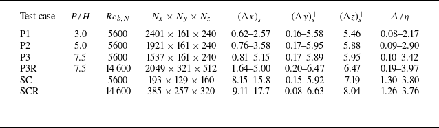


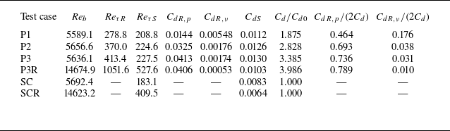


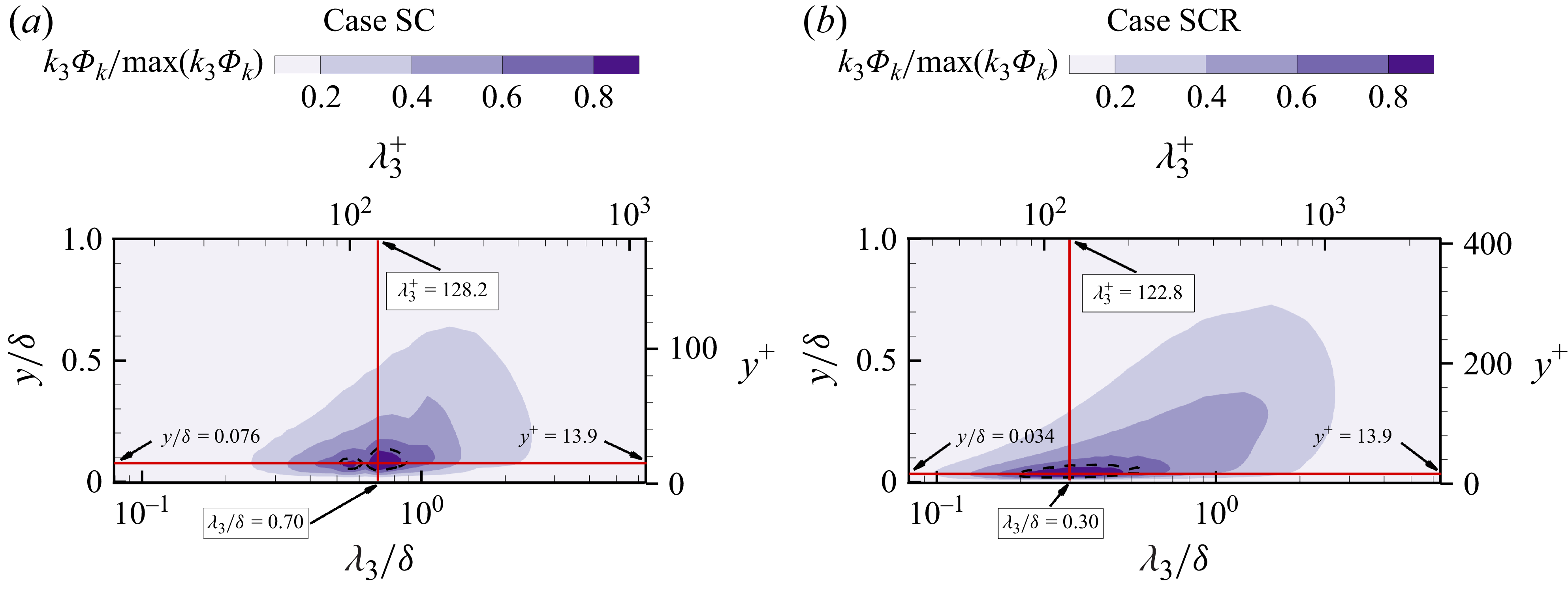


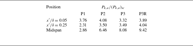


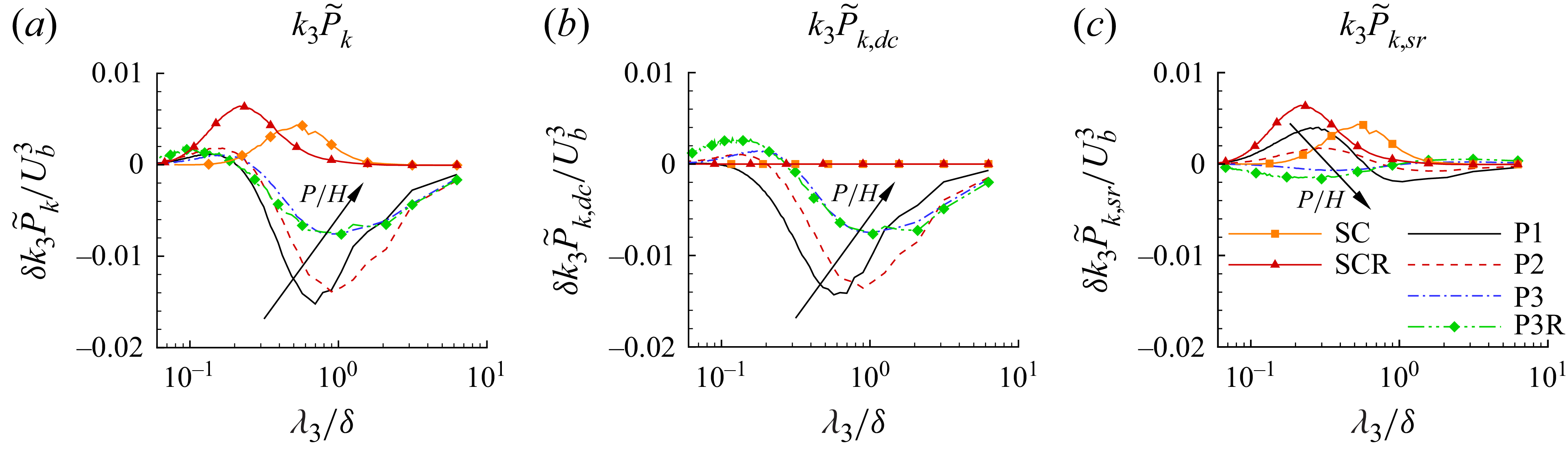


 Open access