





1. Introduction
The origin of high-energy emissions in the Universe is often a non-thermal power-law spectrum of relativistic particles. Therefore, to explain high-energy emissions, it is necessary to understand how power-law distributions of non-thermal particles are populated and sustained, with the former being the concern of injection studies and the latter being the concern of studies about non-thermal particle acceleration to high energies.
The question of how a power-law distribution of particles is populated may be decomposed into two questions: (i) Under what conditions are particles injected, i.e. eligible to participate in a continual, power-law-forming acceleration process? (ii) What physical mechanisms are responsible for injection?
Regarding the first question, the injection criterion has typically been expressed since Fermi (Reference Fermi1949) as an energy threshold $\gamma _{\textrm {inj}}$
that a particle must surpass, so that particles with energy
$\gamma _{\textrm {inj}}$
that a particle must surpass, so that particles with energy $\gamma \gt \gamma _{\textrm { inj}}$
are ‘injected’ and can experience further Fermi acceleration to even higher energies, whereas those with
$\gamma \gt \gamma _{\textrm { inj}}$
are ‘injected’ and can experience further Fermi acceleration to even higher energies, whereas those with $\gamma \lt \gamma _{\textrm {inj}}$
cannot. Physically, this may be owed to the relativistic gyroradius of particles scaling linearly with
$\gamma \lt \gamma _{\textrm {inj}}$
cannot. Physically, this may be owed to the relativistic gyroradius of particles scaling linearly with $\gamma$
, which facilitates acceleration via stochastic scattering off of turbulent fluctuations (Lemoine & Malkov Reference Lemoine and Malkov2020). In this study, we also presuppose that
$\gamma$
, which facilitates acceleration via stochastic scattering off of turbulent fluctuations (Lemoine & Malkov Reference Lemoine and Malkov2020). In this study, we also presuppose that $\gamma _{\textrm {inj}}$
exists and define it as the low-energy boundary of the non-thermal power-law segment of the downstream particle distribution function. Thus, the first question is recast as a problem of relating
$\gamma _{\textrm {inj}}$
exists and define it as the low-energy boundary of the non-thermal power-law segment of the downstream particle distribution function. Thus, the first question is recast as a problem of relating $\gamma _{\textrm {inj}}$
to the system parameters and explaining the connection.
$\gamma _{\textrm {inj}}$
to the system parameters and explaining the connection.
Accordingly, the second question is also recast: it is to understand what ‘injection mechanisms’ – mechanisms that accelerate particles from a thermal upstream to or beyond the injection energy $\gamma _{\textrm {inj}}$
that gates the non-thermal power-law spectrum – are active, how much work they do to each particle and upon how many particles they act.
$\gamma _{\textrm {inj}}$
that gates the non-thermal power-law spectrum – are active, how much work they do to each particle and upon how many particles they act.
These questions of particle injection have been largely unresolved across several processes that are thought to power high-energy emissions in relativistic astrophysical environments, such as jets from active galactic nuclei, pulsar wind nebulae, neutron star magnetospheres and accreting black hole coronae. These processes include relativistic turbulence (Chandran Reference Chandran2000; Zhdankin et al. Reference Zhdankin, Werner, Uzdensky and Begelman2017; Comisso & Sironi Reference Comisso and Sironi2018, Reference Comisso and Sironi2019; Zhdankin et al. Reference Zhdankin, Uzdensky, Werner and Begelman2018, Reference Zhdankin, Uzdensky, Werner and Begelman2019; Lemoine Reference Lemoine2019; Wong et al. Reference Wong, Zhdankin, Uzdensky, Werner and Begelman2020; Demidem, Lemoine & Casse Reference Demidem, Lemoine and Casse2020; Lemoine & Malkov Reference Lemoine and Malkov2020; Guo et al. Reference Guo, French, Zhang, Li and Seo2025; Mehlhaff, Zhou & Zhdankin Reference Mehlhaff, Zhou and Zhdankin2025), collisionless relativistic shocks (Blandford & Ostriker Reference Blandford and Ostriker1978; Blandford & Eichler Reference Blandford and Eichler1987; Spitkovsky Reference Spitkovsky2008; Sironi & Spitkovsky Reference Sironi and Spitkovsky2011; Caprioli & Spitkovsky Reference Caprioli and Spitkovsky2014; Parsons, Spitkovsky & Vanthieghem Reference Parsons, Spitkovsky and Vanthieghem2024) and relativistic magnetic reconnection (Bulanov & Sasorov Reference Bulanov and Sasorov1976; Blackman & Field Reference Blackman and Field1994; Zenitani & Hoshino Reference Zenitani and Hoshino2001; Jaroschek, Lesch & Treumann Reference Jaroschek, Lesch and Treumann2004; Giannios, Uzdensky & Begelman Reference Giannios, Uzdensky and Begelman2010; Cerutti et al. Reference Cerutti, Werner, Uzdensky and Begelman2013; Sironi & Spitkovsky Reference Sironi and Spitkovsky2014; Melzani et al. Reference Melzani, Walder, Folini, Winisdoerffer and Favre2014; Guo et al. Reference Guo, Li, Daughton and Liu2014, Reference Guo, Liu, Daughton and Li2015, Reference Guo, Li, Li, Daughton, Zhang, Lloyd-Ronning, Liu, Zhang and Deng2016, Reference Guo, Li, Daughton, Kilian, Li, Liu, Yan and Ma2019; Nalewajko et al. Reference Nalewajko, Uzdensky, Cerutti, Werner and Begelman2015; Werner et al. Reference Werner, Uzdensky, Cerutti, Nalewajko and Begelman2016; Rowan, Sironi & Narayan Reference Rowan, Sironi and Narayan2017; Werner & Uzdensky Reference Werner and Uzdensky2017; Petropoulou & Sironi Reference Petropoulou and Sironi2018; Werner et al. Reference Werner, Uzdensky, Begelman, Cerutti and Nalewajko2018; Schoeffler et al. Reference Schoeffler, Grismayer, Uzdensky, Fonseca and Silva2019; Kilian et al. Reference Kilian, Li, Guo and Zhang2020; Mehlhaff et al. Reference Mehlhaff, Werner, Uzdensky and Begelman2020; Hakobyan et al. Reference Hakobyan, Petropoulou, Spitkovsky and Sironi2021; Werner & Uzdensky Reference Werner and Uzdensky2021; Sironi Reference Sironi2022; Uzdensky Reference Uzdensky2022; French et al. Reference French, Guo, Zhang and Uzdensky2023; Li et al. Reference Li, Guo, Liu and Li2023; Zhang et al. Reference Zhang, Sironi, Giannios and Petropoulou2023; Gupta, Sridhar & Sironi Reference Gupta, Sridhar and Sironi2025) (see Guo et al. Reference Guo, Liu, Zenitani and Hoshino2024; Sironi, Uzdensky & Giannios Reference Sironi, Uzdensky and Giannios2025, for recent reviews).
In the context of relativistic magnetic reconnection, several injection and high-energy acceleration mechanisms have been studied, both analytically and numerically via fully kinetic particle-in-cell (PIC) simulations: ‘direct’ acceleration by the parallel electric field with a finite guide magnetic field (i.e. a finite non-reversing, out-of-plane component of the magnetic field) near X-points (Larrabee, Lovelace & Romanova Reference Larrabee, Lovelace and Romanova2003; Zenitani & Hoshino Reference Zenitani and Hoshino2005, Reference Zenitani and Hoshino2008; Cerutti et al. Reference Cerutti, Werner, Uzdensky and Begelman2013, Reference Cerutti, Werner, Uzdensky and Begelman2014; Ball, Sironi & Özel Reference Ball, Sironi and Özel2019; Sironi Reference Sironi2022; Totorica et al. Reference Totorica, Zenitani, Matsukiyo, Machida, Sekiguchi and Bhattacharjee2023; Gupta et al. Reference Gupta, Sridhar and Sironi2025), Speiser orbits in the case of zero guide field (Speiser Reference Speiser1965; Hoshino et al. Reference Hoshino, Mukai, Terasawa and Shinohara2001; Zenitani & Hoshino Reference Zenitani and Hoshino2001; Uzdensky, Cerutti & Begelman Reference Uzdensky, Cerutti and Begelman2011; Cerutti et al. Reference Cerutti, Uzdensky and Begelman2012, Reference Cerutti, Werner, Uzdensky and Begelman2013, Reference Cerutti, Werner, Uzdensky and Begelman2014; Nalewajko et al. Reference Nalewajko, Uzdensky, Cerutti, Werner and Begelman2015; Uzdensky Reference Uzdensky2022), Fermi acceleration (Fermi Reference Fermi1949; Drake et al. Reference Drake, Swisdak, Che and Shay2006; Giannios et al. Reference Giannios, Uzdensky and Begelman2010; Guo et al. Reference Guo, Li, Daughton and Liu2014, Reference Guo, Liu, Daughton and Li2015; Dahlin, Drake & Swisdak Reference Dahlin, Drake and Swisdak2014; Zhang et al. Reference Zhang, Guo, Daughton, Li and Li2021; French et al. Reference French, Guo, Zhang and Uzdensky2023; Zhang et al. Reference Zhang, Guo, Daughton, Li, Le, Phan and Desai2024), parallel electric field acceleration in the exhaust region (Egedal & Daughton Reference Egedal and Daughton2013; Zhang, Drake & Swisdak Reference Zhang, Drake and Swisdak2019) and acceleration by the pickup process in the exhaust region (Drake et al. Reference Drake, Cassak, Shay, Swisdak and Quataert2009; Sironi & Beloborodov Reference Sironi and Beloborodov2020; Chernoglazov, Hakobyan & Philippov Reference Chernoglazov, Hakobyan and Philippov2023; French et al. Reference French, Guo, Zhang and Uzdensky2023). Previous work on particle injection in magnetic reconnection has included studies in the transrelativistic regime for a proton–electron plasma with a weak guide field (Ball et al. Reference Ball, Sironi and Özel2019; Kilian et al. Reference Kilian, Li, Guo and Zhang2020) and relativistic pair plasmas for various guide-field strengths (Sironi Reference Sironi2022; French et al. Reference French, Guo, Zhang and Uzdensky2023; Guo et al. Reference Guo, Li, French, Zhang, Daughton, Liu, Matthaeus, Kilian, Johnson and Li2023; Totorica et al. Reference Totorica, Zenitani, Matsukiyo, Machida, Sekiguchi and Bhattacharjee2023) and upstream magnetisations (Sironi Reference Sironi2022; Guo et al. Reference Guo, Li, French, Zhang, Daughton, Liu, Matthaeus, Kilian, Johnson and Li2023; Totorica et al. Reference Totorica, Zenitani, Matsukiyo, Machida, Sekiguchi and Bhattacharjee2023; Gupta et al. Reference Gupta, Sridhar and Sironi2025).
However, these studies have not elucidated several important aspects of injection, such as how the injection stage in relativistic magnetic reconnection is influenced by the upstream magnetisation and three-dimensional (3-D) effects. Addressing this key question is the subject of this paper. We achieve this using analytical theory and fully kinetic 2-D and 3-D PIC simulations of relativistic magnetic reconnection in non-radiative collisionless pair plasmas. To uncover spectral quantities, most importantly the injection energy $\gamma _{\textrm {inj}}$
, we run a spectral fitting procedure that is improved from our previous work (French et al. Reference French, Guo, Zhang and Uzdensky2023). To uncover the relative contributions of different injection mechanisms, we employ a methodology similar to French et al. (Reference French, Guo, Zhang and Uzdensky2023), wherein we consider several mechanisms, namely, parallel electric fields near X-points, Fermi kicks by the motional electric field and the pickup process.
$\gamma _{\textrm {inj}}$
, we run a spectral fitting procedure that is improved from our previous work (French et al. Reference French, Guo, Zhang and Uzdensky2023). To uncover the relative contributions of different injection mechanisms, we employ a methodology similar to French et al. (Reference French, Guo, Zhang and Uzdensky2023), wherein we consider several mechanisms, namely, parallel electric fields near X-points, Fermi kicks by the motional electric field and the pickup process.
Throughout this paper, we use the units $m_e = c = 1$
. That is, we normalise velocities to the speed of light
$m_e = c = 1$
. That is, we normalise velocities to the speed of light $c$
, momenta to
$c$
, momenta to $m_e c$
and energies to the electron rest energy
$m_e c$
and energies to the electron rest energy $m_e c^2$
. Furthermore, we denote
$m_e c^2$
. Furthermore, we denote $\gamma$
as the energy of a single particle,
$\gamma$
as the energy of a single particle, $E$
as the sum or integral of energies of multiple particles, and
$E$
as the sum or integral of energies of multiple particles, and $\boldsymbol{v}$
as the particle 3-velocity in the simulation frame. Primed vector quantities, such as the velocity
$\boldsymbol{v}$
as the particle 3-velocity in the simulation frame. Primed vector quantities, such as the velocity $\boldsymbol{v}'$
or the momentum
$\boldsymbol{v}'$
or the momentum $\boldsymbol{p}' \equiv \gamma ' \boldsymbol{v}'$
, denote a Lorentz boost to the
$\boldsymbol{p}' \equiv \gamma ' \boldsymbol{v}'$
, denote a Lorentz boost to the $\boldsymbol{v}_E \equiv \boldsymbol{E} \times \boldsymbol{B}/B^2$
drift-velocity frame, where
$\boldsymbol{v}_E \equiv \boldsymbol{E} \times \boldsymbol{B}/B^2$
drift-velocity frame, where $\boldsymbol{E}$
and
$\boldsymbol{E}$
and $\boldsymbol{B}$
respectively denote the electric and magnetic field vectors. This is done to eliminate the context of bulk plasma motions. Primed scalar quantities denote those whose vector inputs are primed, e.g.
$\boldsymbol{B}$
respectively denote the electric and magnetic field vectors. This is done to eliminate the context of bulk plasma motions. Primed scalar quantities denote those whose vector inputs are primed, e.g. $\gamma ' \equiv (1 - \boldsymbol{v}' \boldsymbol{\cdot }\boldsymbol{v}')^{-1/2}$
. Subscripts
$\gamma ' \equiv (1 - \boldsymbol{v}' \boldsymbol{\cdot }\boldsymbol{v}')^{-1/2}$
. Subscripts $\parallel , \perp$
indicate components relative to the local magnetic field in the laboratory frame (
$\parallel , \perp$
indicate components relative to the local magnetic field in the laboratory frame ( $E \times B$
drift-velocity frame) if the quantity is not primed (primed). Lastly, we reference four dimensionless quantities used throughout this paper: the cold upstream magnetisation
$E \times B$
drift-velocity frame) if the quantity is not primed (primed). Lastly, we reference four dimensionless quantities used throughout this paper: the cold upstream magnetisation
 \begin{equation} \sigma \equiv B_0^2/4\pi nm_ec^2, \end{equation}
corresponding to the average magnetic energy per particle rest mass energy (where $B_0$
is the ambient upstream magnetic field and
$B_0$
is the ambient upstream magnetic field and $n \equiv n_i + n_e$
is the total upstream plasma density), the hot upstream magnetisation
$n \equiv n_i + n_e$
is the total upstream plasma density), the hot upstream magnetisation
 \begin{equation} \sigma _h \equiv B_0^2/4\pi h, \end{equation}
where $h$
is the relativistic plasma enthalpy density, the ambient upstream temperature normalised by particle rest mass energy
$h$
is the relativistic plasma enthalpy density, the ambient upstream temperature normalised by particle rest mass energy
 \begin{equation} \theta _0 \equiv k_BT_0/m_e c^2, \end{equation}
and the normalised guide-field strength
 \begin{equation} b_g \equiv B_g/B_0, \end{equation}
where $B_g$
is the `guide magnetic field,’ a uniform, non-reversing component of the magnetic field that orients out of plane.
$B_g$
is the `guide magnetic field,’ a uniform, non-reversing component of the magnetic field that orients out of plane.
The rest of this paper is organised as follows. Section 2 presents our theoretical picture of particle injection. Section 3 describes the set-up for the simulations. Section 4 contains the analysis and results from each simulation. Section 5 discusses comparisons with previous work and outlooks for future work. Section 6 presents our main conclusions.
2. Theoretical picture of particle injection
In concordance with our overview in § 1, our picture of particle injection in relativistic magnetic reconnection has two components. The first is an analytical model for the injection energy $\gamma _{\textrm {inj}}$
(§ 2.1). The second is a detailed description of each mechanism that injects particles (§ 2.2).
$\gamma _{\textrm {inj}}$
(§ 2.1). The second is a detailed description of each mechanism that injects particles (§ 2.2).
2.1. Injection criterion
Suppose the criterion for a particle to be ‘injected’, regardless of the mechanism of injection, is that its gyroradius $r_g$
exceeds the reconnection layer half-thickness at the X-point
$r_g$
exceeds the reconnection layer half-thickness at the X-point $\delta /2$
, i.e.
$\delta /2$
, i.e. $r_g \geqslant \delta /2 \implies \gamma \geqslant \gamma _{\textrm {inj}}$
(Speiser Reference Speiser1965; Giannios et al. Reference Giannios, Uzdensky and Begelman2010). This criterion ensures that a gyrating particle centred on the X-point spends some fraction of each orbit outside the layer, which causes it to adopt a meandering Speiser trajectory. It follows that a newly injected particle will satisfy
$r_g \geqslant \delta /2 \implies \gamma \geqslant \gamma _{\textrm {inj}}$
(Speiser Reference Speiser1965; Giannios et al. Reference Giannios, Uzdensky and Begelman2010). This criterion ensures that a gyrating particle centred on the X-point spends some fraction of each orbit outside the layer, which causes it to adopt a meandering Speiser trajectory. It follows that a newly injected particle will satisfy
 \begin{equation} \delta = 2 r_g(\gamma = \gamma _{\textrm {inj}}) = 2 \gamma _{\textrm {inj}} v_\perp \frac {m_e c}{eB} = 2 \gamma _{\textrm {inj}} v_\perp \, \omega _{\textrm {ce}}^{-1} \big ( 1 + b_g^2 \big )^{-1/2} \simeq 2 \gamma _{\textrm {inj}} c \, \omega _{\textrm {ce}}^{-1} \big ( 1 + b_g^2 \big )^{-1/2} \end{equation}
 \begin{equation} \implies \gamma _{\textrm {inj}} \simeq \frac {\delta }{2} \frac {\omega _{\textrm {ce}}}{c} \sqrt {1 + b_g^2} = \frac {1}{2} \frac {\delta }{\rho _0} \sqrt {1 + b_g^2}, \end{equation}
where $\omega _{\textrm {ce}} \equiv eB_0/m_e c$
is the nominal electron gyrofrequency defined with the upstream magnetic field
$\omega _{\textrm {ce}} \equiv eB_0/m_e c$
is the nominal electron gyrofrequency defined with the upstream magnetic field $B_0$
and
$B_0$
and $\rho _0 \equiv c/\omega _{\textrm {ce}} = m_e c^2/eB_0$
is the corresponding nominal relativistic gyroradius. In (2.1) we have ignored pitch angle corrections and assumed
$\rho _0 \equiv c/\omega _{\textrm {ce}} = m_e c^2/eB_0$
is the corresponding nominal relativistic gyroradius. In (2.1) we have ignored pitch angle corrections and assumed $v_\perp \simeq c$
.
$v_\perp \simeq c$
.
Our next task is to estimate the layer thickness $\delta$
at the X-point. We shall take
$\delta$
at the X-point. We shall take $\delta \simeq d_{\textrm {e, rel}}$
, where
$\delta \simeq d_{\textrm {e, rel}}$
, where $d_{\textrm {e, rel}}$
is the relativistic collisionless electron skin depth inside the layer, and assume that the electron density in the layer is comparable to the ambient upstream electron density
$d_{\textrm {e, rel}}$
is the relativistic collisionless electron skin depth inside the layer, and assume that the electron density in the layer is comparable to the ambient upstream electron density $n_e$
. Additionally, we assume that the velocity distribution is isotropic in the layer. Then,
$n_e$
. Additionally, we assume that the velocity distribution is isotropic in the layer. Then,
 \begin{equation} \delta \simeq d_{\textrm {e, rel}} = c \, \omega _{\textrm {pe, rel}}^{-1} = \sqrt {\varGamma } \, c \, \omega _{\textrm {pe}}^{-1}, \end{equation}
where $\omega _{\textrm {pe}} \equiv [ 4\pi n_e e^2 / m_e ]^{1/2}$
is the corresponding electron plasma frequency and
$\omega _{\textrm {pe}} \equiv [ 4\pi n_e e^2 / m_e ]^{1/2}$
is the corresponding electron plasma frequency and $\varGamma$
is the mean Lorentz factor of electrons in the layer.
$\varGamma$
is the mean Lorentz factor of electrons in the layer.
Substituting (2.3) into (2.2), we obtain
 \begin{equation} \gamma _{\textrm {inj}} \simeq \sqrt {\varGamma \, \sigma \, (1 + b_g^2)/2}, \end{equation}
where for a pair plasma $\sigma = \sigma _e/2 = \omega _{\textrm {ce}}^2/(2\omega _{\textrm {pe}}^2)$
is the upstream magnetisation.
$\sigma = \sigma _e/2 = \omega _{\textrm {ce}}^2/(2\omega _{\textrm {pe}}^2)$
is the upstream magnetisation.
The remaining task is to model $\varGamma$
, which can be represented as the sum of two contributions
$\varGamma$
, which can be represented as the sum of two contributions
 \begin{equation} \varGamma = \varGamma _{\textrm {up}} + \frac {\langle W \rangle }{m_e c^2}, \end{equation}
where $\varGamma _{\textrm {up}}$
is the average Lorentz factor of particles arriving from the upstream and
$\varGamma _{\textrm {up}}$
is the average Lorentz factor of particles arriving from the upstream and $\langle W \rangle$
is the average work done to particles while they are in the layer. If the upstream particle distribution is thermal, then
$\langle W \rangle$
is the average work done to particles while they are in the layer. If the upstream particle distribution is thermal, then $\varGamma _{\textrm {up}} = \varGamma _{\textrm {th}} = K_3(1/\theta _0)/K_2(1/\theta _0)$
, where
$\varGamma _{\textrm {up}} = \varGamma _{\textrm {th}} = K_3(1/\theta _0)/K_2(1/\theta _0)$
, where $\varGamma _{\textrm {th}} = K_3(1/\theta _0)/K_2(1/\theta _0)$
is the ‘thermal Lorentz factor’, i.e. the average energy of electrons in a Maxwell–Jüttner distribution of upstream temperature
$\varGamma _{\textrm {th}} = K_3(1/\theta _0)/K_2(1/\theta _0)$
is the ‘thermal Lorentz factor’, i.e. the average energy of electrons in a Maxwell–Jüttner distribution of upstream temperature $\theta _0 \equiv k_B T_0/m_e c^2$
.
$\theta _0 \equiv k_B T_0/m_e c^2$
.
Meanwhile, $\langle W \rangle$
can generally be written
$\langle W \rangle$
can generally be written $\langle W \rangle = k\sigma m_ec^2$
, where one expects the dimensionless coefficient
$\langle W \rangle = k\sigma m_ec^2$
, where one expects the dimensionless coefficient $k\gt 0$
to be a constant independent of
$k\gt 0$
to be a constant independent of $\sigma$
. We may constrain
$\sigma$
. We may constrain $k$
as follows. First,
$k$
as follows. First, $U_B = B_0^2/8\pi$
implies that the available magnetic energy per particle is
$U_B = B_0^2/8\pi$
implies that the available magnetic energy per particle is $U_B/n = B_0^2/(8\pi n) = (\sigma /2) m_e c^2$
. Second, assuming that the efficiency of energy conversion is
$U_B/n = B_0^2/(8\pi n) = (\sigma /2) m_e c^2$
. Second, assuming that the efficiency of energy conversion is ${\sim} 50\,\%$
, the average dissipated magnetic energy per particle is
${\sim} 50\,\%$
, the average dissipated magnetic energy per particle is ${\simeq} (\sigma /4) m_ec^2$
. Third, since the particles are energised partially as they enter the current sheet and partially as they exit the current sheet (e.g. by magnetic tension release in the outwards-accelerating plasma), we may assume that the average dissipated magnetic energy per particle that exists in the current sheet is
${\simeq} (\sigma /4) m_ec^2$
. Third, since the particles are energised partially as they enter the current sheet and partially as they exit the current sheet (e.g. by magnetic tension release in the outwards-accelerating plasma), we may assume that the average dissipated magnetic energy per particle that exists in the current sheet is $\lesssim (\sigma /8) m_ec^2$
. This gives a constraint of
$\lesssim (\sigma /8) m_ec^2$
. This gives a constraint of $k \lesssim 1/8$
. We stress that, while the exact value of
$k \lesssim 1/8$
. We stress that, while the exact value of $k$
is uncertain, the above argument allows us to treat
$k$
is uncertain, the above argument allows us to treat $k$
as a small parameter. Accordingly, we shall retain
$k$
as a small parameter. Accordingly, we shall retain $k$
in the rest of this subsection.
$k$
in the rest of this subsection.
We can now write (2.5) as
 \begin{equation} \varGamma = \varGamma _{\textrm {th}} + k \, \sigma \simeq \varGamma _{\textrm {th}} \big [ 1 + k \, \sigma _h \big ] = \sigma \big [ \sigma _h^{-1} + k \big ], \end{equation}
where we approximate $\sigma _h \simeq \sigma /\varGamma _{\textrm {th}}$
. We see that there are two distinct relativistic (
$\sigma _h \simeq \sigma /\varGamma _{\textrm {th}}$
. We see that there are two distinct relativistic ( $\sigma _h \gg 1$
) regimes based on which of the two terms in (2.6) dominates, i.e. how
$\sigma _h \gg 1$
) regimes based on which of the two terms in (2.6) dominates, i.e. how $\sigma _h$
compares with
$\sigma _h$
compares with $k^{-1}$
:
$k^{-1}$
:
-
(i) Thermally dominated regime $1 \lesssim \sigma _h \lesssim k^{-1}$
. In this moderate-magnetisation case (covering
$\gtrsim 1$
decade in
$\sigma _h$
), the average particle energy in layer is
$\varGamma \simeq \varGamma _{\textrm {th}}$
, i.e. inherited from the thermal upstream and not controlled by
$\sigma$
or reconnection. In this regime, the upstream plasma conditions fully govern the layer thickness and partially govern the injection energy
$\gamma _{\textrm {inj}}$
. In particular, the injection energy according to (2.4) becomes(2.7)In particular,
\begin{equation} \gamma _{\textrm {inj}} \simeq \sigma \sqrt {\sigma _h^{-1} \, (1 + b_g^2)/2}. \end{equation}
(2.8)
\begin{equation} \gamma _{\textrm {inj}} \simeq \begin{cases} \sqrt {\sigma (1 + b_g^2)/2}, & \theta \ll 1, \\ \sqrt {\varGamma _{\textrm {th}} \sigma (1 + b_g^2)/2}, & \theta \gg 1 .\end{cases} \end{equation}
$1 \lesssim \sigma _h \lesssim k^{-1}$
. In this moderate-magnetisation case (covering
$\gtrsim 1$
decade in
$\sigma _h$
), the average particle energy in layer is
$\varGamma \simeq \varGamma _{\textrm {th}}$
, i.e. inherited from the thermal upstream and not controlled by
$\sigma$
or reconnection. In this regime, the upstream plasma conditions fully govern the layer thickness and partially govern the injection energy
$\gamma _{\textrm {inj}}$
. In particular, the injection energy according to (2.4) becomes(2.7)In particular,
\begin{equation} \gamma _{\textrm {inj}} \simeq \sigma \sqrt {\sigma _h^{-1} \, (1 + b_g^2)/2}. \end{equation}
(2.8)
\begin{equation} \gamma _{\textrm {inj}} \simeq \begin{cases} \sqrt {\sigma (1 + b_g^2)/2}, & \theta \ll 1, \\ \sqrt {\varGamma _{\textrm {th}} \sigma (1 + b_g^2)/2}, & \theta \gg 1 .\end{cases} \end{equation}
-
(ii) Magnetically dominated regime
$\sigma _h \gg k^{-1}$
. In this case, the average particle energy in the layer
$\varGamma$
is dominated by
$\langle W \rangle /m_e c^2$
and upstream contributions can be ignored. Hence (2.4) becomes(2.9)
\begin{equation} \gamma _{\textrm {inj}} \simeq \sigma \sqrt {k (1 + b_g^2)/2}. \end{equation}


There are several implications for the resulting dynamic range of the power-law spectrum. Assuming that $\gamma _c = C \sigma$
(Werner et al. Reference Werner, Uzdensky, Cerutti, Nalewajko and Begelman2016), one expects
$\gamma _c = C \sigma$
(Werner et al. Reference Werner, Uzdensky, Cerutti, Nalewajko and Begelman2016), one expects
 \begin{equation} R \equiv \gamma _c/\gamma _{\textrm {inj}} \simeq \begin{cases} \sqrt {2}C \, \sigma _h^{1/2} \left [ 1 + b_g^2 \right ]^{-1/2} & 1 \lesssim \sigma _h \lesssim k^{-1} ,\\ \sqrt {2}C \, k^{-1/2} \left [ 1 + b_g^2 \right ]^{-1/2} & \sigma _h \gg k^{-1}. \\ \end{cases} \end{equation}
In this model, the explicit guide-field dependence of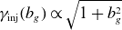 $\gamma _{\textrm {inj}}(b_g) \propto \sqrt {1 + b_g^2}$
is owed to stronger magnetic fields decreasing the particle gyroradius, resulting in a greater energy necessary to satisfy
$\gamma _{\textrm {inj}}(b_g) \propto \sqrt {1 + b_g^2}$
is owed to stronger magnetic fields decreasing the particle gyroradius, resulting in a greater energy necessary to satisfy $r_g \geqslant \delta /2$
. There could also be an implicit guide-field dependence if the layer thickness depends on guide-field strength. This is plausible because a strong guide field can prolong the duration over which particles remain in the X-point, causing
$r_g \geqslant \delta /2$
. There could also be an implicit guide-field dependence if the layer thickness depends on guide-field strength. This is plausible because a strong guide field can prolong the duration over which particles remain in the X-point, causing $k$
to increase. Nevertheless, as we shall find in § 5.1, the scaling
$k$
to increase. Nevertheless, as we shall find in § 5.1, the scaling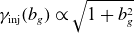 $\gamma _{\textrm {inj}}(b_g) \propto \sqrt {1 + b_g^2}$
is in rough agreement with French et al. (Reference French, Guo, Zhang and Uzdensky2023).
$\gamma _{\textrm {inj}}(b_g) \propto \sqrt {1 + b_g^2}$
is in rough agreement with French et al. (Reference French, Guo, Zhang and Uzdensky2023).
2.2. Injection mechanisms
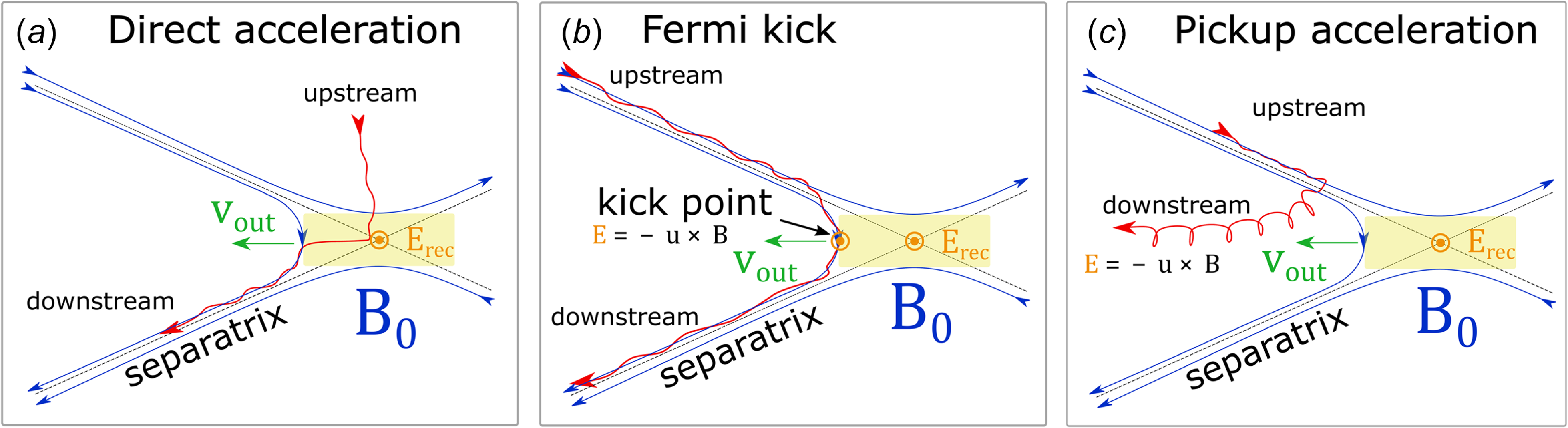
In our first paper (French et al. Reference French, Guo, Zhang and Uzdensky2023), we stipulated that particles can be injected only as they transition from upstream to downstream, i.e. as they cross or interact with the magnetic separatrix between these two regions. Applying this assumption in the context of a reconnection layer has led to the identification of the following three injection mechanisms (French et al. Reference French, Guo, Zhang and Uzdensky2023), illustrated in figure 1.
Cartoons of several particle injection mechanisms, adapted from French et al. (Reference French, Guo, Zhang and Uzdensky2023). In each panel, $B_0$
is the reconnecting magnetic field,
$B_0$
is the reconnecting magnetic field, $E_{\textrm {rec}}$
is the reconnection electric field and
$E_{\textrm {rec}}$
is the reconnection electric field and $v_{\textrm {out}}$
is the reconnection outflow speed. (a) Injection by direct acceleration from the reconnection electric field near an X-point. (b) Injection by a Fermi `kick.’ (c) Injection by the pickup process, wherein
$v_{\textrm {out}}$
is the reconnection outflow speed. (a) Injection by direct acceleration from the reconnection electric field near an X-point. (b) Injection by a Fermi `kick.’ (c) Injection by the pickup process, wherein $\lvert \boldsymbol{p}_\perp '\rvert$
suddenly increases upon crossing the separatrix and subsequent entry into the downstream region.
$\lvert \boldsymbol{p}_\perp '\rvert$
suddenly increases upon crossing the separatrix and subsequent entry into the downstream region.
-
(a) Direct acceleration: incoming particles are accelerated directly by the reconnection electric field
$E_{\textrm {rec}}$
in microscopic diffusion regions around magnetic X-points (figure 1
a). When immersed in
$E_{\textrm {rec}}$
, charged particles gain energy at a rate of
$\dot {W}_{\textrm {direct}} = ( \eta _{\textrm {rec}} \beta _A \omega _{\textrm {ce}}) m_e c^2$
, where
$\eta _{\textrm {rec}} \beta _A \equiv E_{\textrm {rec}}/B_0 \simeq 0.1$
(when the guide magnetic field is weak) is the reconnection rate normalised by the speed of light, where
$\beta _A \equiv [ \sigma _h/(1+\sigma _h) ]^{1/2} \simeq [ \sigma /(1+\sigma ) ]^{1/2}$
is the dimensionless upstream Alfvén speed (provided the upstream plasma is relativistically cold, i.e.
$\theta _0 \equiv k_B T_0 / m_e c^2 \ll 1$
) and
$\omega _{\textrm {ce}} \equiv eB_0/m_ec$
. Hence(2.11)If a guide field
\begin{equation} W_{\textrm {direct}}/m_ec^2 = \eta _{\textrm {rec}} \beta _A \big ( \omega _{\textrm {ce}} \Delta t\big ) \simeq 0.1 \, \omega _{\textrm {ce}} \Delta t. \end{equation}
$b_g \equiv B_g/B_0 \gtrsim \eta _{\textrm {rec}} \simeq 0.1$
is present, then
$E_{\textrm {rec}}$
is well approximated by the parallel electric field
$\lvert \boldsymbol{E}_\parallel \rvert \equiv (\boldsymbol{E} \boldsymbol{\cdot }\boldsymbol{B}) /\lvert \boldsymbol{B} \rvert$
at the X-point where the in-plane magnetic field vanishes. In this case, particles gain significant parallel momentum
$\boldsymbol{p}'_\parallel \equiv \gamma ' \boldsymbol{v}'_\parallel = \gamma \boldsymbol{v}_\parallel = \gamma (\boldsymbol{v} \boldsymbol{\cdot }\boldsymbol{B}) \boldsymbol{B}/\lvert \boldsymbol{B} \rvert ^2$
.
-
(b) Fermi kick: the relaxation of freshly reconnected magnetic field-line tension gives rise to a Fermi acceleration process wherein the local curvature drift velocity
$\boldsymbol{v}_C$
of particles is aligned with the motional electric field of ideal magnetohydrodynamics (MHD)
$\boldsymbol{E}_m = - \boldsymbol{u} \times \boldsymbol{B}$
associated with the rapid advection of the newly reconnected magnetic field lines (Drake et al. Reference Drake, Swisdak, Che and Shay2006; Dahlin et al. Reference Dahlin, Drake and Swisdak2014; Guo et al. Reference Guo, Li, Daughton and Liu2014; Li et al. Reference Li, Guo, Li and Li2018; Kilian et al. Reference Kilian, Li, Guo and Zhang2020; Zhang et al. Reference Zhang, Guo, Daughton, Li and Li2021; French et al. Reference French, Guo, Zhang and Uzdensky2023; Majeski & Ji Reference Majeski and Ji2023; Zhang et al. Reference Zhang, Guo, Daughton, Li, Le, Phan and Desai2024). This mechanism is illustrated in figure 1(b).Consequently, an incoming particle experiences one Fermi reflection (or ‘kick’, i.e. one half-cycle of a continual Fermi process) that flips its direction in the
$E \times B$
drift frame. If the Fermi kick is treated as a 1-D collision, then the net energy gain is obtained by considering the particle’s initial velocity in the outflow (i.e.
$E \times B$
-drift) frame projected onto the outflow direction,
$\beta _i'$
, negating it (i.e.
$\beta _f' = -\beta _i'$
), and boosting back to the simulation frame. Assuming that the outflow speed is the in-plane Alfvén speed, the result is a velocity gain of(2.12)where
\begin{align} \Delta \beta \equiv \beta _f - \beta _i = \frac {2\beta _{\textrm {Ax}} \big [ 1 + \beta _i^2 \big ] - 2\beta _i \big [ 1 + \beta _{\textrm {Ax}}^2 \big ]}{ \big [ 1 + \beta _{\textrm {Ax}}^2 \big ] -2 \beta _i \beta _{\textrm {Ax}} }, \end{align}
$\beta _j \equiv v_j/c$
for any subscript
$j$
and
$\beta _{\textrm {Ax}}$
is the in-plane Alfvén speed
$\beta _{\textrm {Ax}} = [ \sigma /[1 + \sigma (1 + b_g^2)] ]^{1/2}$
. As
$\beta _i \to 0$
(i.e. for particles with initial velocity nearly perpendicular to the outflow), the resulting energy gain becomes(2.13)Hence a strong guide field (i.e.
\begin{equation} W_{\textrm {Fermi}}/m_ec^2 = \lim _{\beta _i \to 0} \big ( 1 - (\Delta \beta )^2 \big )^{-1/2} - 1 = \frac {1 + \beta _{\textrm {Ax}}^2}{1 - \beta _{\textrm {Ax}}^2} - 1 = \frac {2\sigma }{1 + \sigma b_g^2}. \end{equation}
$b_g \gg \sigma ^{-1/2}$
) significantly damps Fermi kicks, resulting in an energisation of
$W_{\textrm {Fermi}} \simeq 2 b_g^{-2} \ll 2\sigma$
. Conversely, a weak guide field (
$b_g \ll \sigma ^{-1/2}$
) allows efficient energisation with
$W_{\textrm {Fermi}} \simeq 2\sigma$
.
-
(c) Pickup acceleration: an incoming upstream particle crosses the reconnection separatrix suddenly and thus (i) the particle’s magnetic moment in the outflow frame
$\mu ' \equiv \gamma ' \lvert \boldsymbol{p}'_\perp \rvert ^2 / 2 \lvert \boldsymbol{B}' \rvert$
is no longer constant, resulting in a greater perpendicular momentum
$\lvert \boldsymbol{p}'_\perp \rvert$
and (ii) the particle becomes immersed in a reconnection outflow with bulk (
$E\times B$
-drift) velocity of
$v_{\textrm {out}} \sim v_{\textrm {Ax}}$
. The ideal-MHD (i.e. motional) electric field
$\boldsymbol{E}_m \equiv - \boldsymbol{u} \times \boldsymbol{B}$
subsequently accelerates the particle until its perpendicular guiding-centre velocity matches the
$E \times B$
-drift velocity of the outflow (figure 1
c) (Drake et al. Reference Drake, Cassak, Shay, Swisdak and Quataert2009; Chernoglazov et al. Reference Chernoglazov, Hakobyan and Philippov2023; French et al. Reference French, Guo, Zhang and Uzdensky2023). Thus the total work done by this pickup mechanism on a particle of initial energy
$\gamma _0$
is(2.14)where
\begin{equation} W_{\textrm {pickup}}/m_ec^2 \equiv \gamma _{\textrm {Ax}} - \gamma _0 = \sqrt {1 + \frac {\sigma }{1 + \sigma b_g^2}} - \gamma _0, \end{equation}
$\gamma _{\textrm {Ax}} = ( 1 - \beta _{\textrm {Ax}}^2)^{-1/2}$
.





























Several strategies have been employed in the literature to disentangle the energetic contribution of each mechanism to particle energisation. One common approach utilises the motional (i.e. ideal) electric field $\boldsymbol{E}_m$
and the non-ideal electric field
$\boldsymbol{E}_m$
and the non-ideal electric field $\boldsymbol{E}_n \equiv \boldsymbol{E} - \boldsymbol{E}_m$
by approximating
$\boldsymbol{E}_n \equiv \boldsymbol{E} - \boldsymbol{E}_m$
by approximating $\boldsymbol{E}_n$
as the electric field component parallel to the local magnetic field,
$\boldsymbol{E}_n$
as the electric field component parallel to the local magnetic field, $\boldsymbol{E}_n \simeq \boldsymbol{E}_\parallel \equiv (\boldsymbol{E} \boldsymbol{\cdot }\boldsymbol{B})\boldsymbol{B}/\lvert \boldsymbol{B} \rvert ^2$
, and
$\boldsymbol{E}_n \simeq \boldsymbol{E}_\parallel \equiv (\boldsymbol{E} \boldsymbol{\cdot }\boldsymbol{B})\boldsymbol{B}/\lvert \boldsymbol{B} \rvert ^2$
, and $\boldsymbol{E}_m$
as the perpendicular component,
$\boldsymbol{E}_m$
as the perpendicular component, $\boldsymbol{E}_m \simeq \boldsymbol{E}_\perp \equiv \boldsymbol{E} - \boldsymbol{E}_\parallel$
; one then compares the works
$\boldsymbol{E}_m \simeq \boldsymbol{E}_\perp \equiv \boldsymbol{E} - \boldsymbol{E}_\parallel$
; one then compares the works $W_\parallel$
and
$W_\parallel$
and $W_\perp$
done by these electric-field components over a statistically large ensemble of tracer particles (Comisso & Sironi Reference Comisso and Sironi2019; Guo et al. Reference Guo, Li, Daughton, Kilian, Li, Liu, Yan and Ma2019; Kilian et al. Reference Kilian, Li, Guo and Zhang2020; French et al. Reference French, Guo, Zhang and Uzdensky2023). Since the value of the normalised guide-field strength adopted in our present study,
$W_\perp$
done by these electric-field components over a statistically large ensemble of tracer particles (Comisso & Sironi Reference Comisso and Sironi2019; Guo et al. Reference Guo, Li, Daughton, Kilian, Li, Liu, Yan and Ma2019; Kilian et al. Reference Kilian, Li, Guo and Zhang2020; French et al. Reference French, Guo, Zhang and Uzdensky2023). Since the value of the normalised guide-field strength adopted in our present study, $b_g = 0.3$
, exceeds the dimensionless reconnection rate
$b_g = 0.3$
, exceeds the dimensionless reconnection rate $\eta _{\textrm {rec}} \simeq 0.1$
(Guo et al. Reference Guo, Liu, Daughton and Li2015; Liu et al. Reference Liu, Guo, Daughton, Li and Hesse2015, Reference Liu, Hesse, Guo, Daughton, Li, Cassak and Shay2017; Werner et al. Reference Werner, Uzdensky, Begelman, Cerutti and Nalewajko2018; Liu et al. Reference Liu, Lin, Hesse, Guo, Li, Zhang and Peery2020; Goodbred & Liu Reference Goodbred and Liu2022; Zhang et al. Reference Zhang, Sironi, Giannios and Petropoulou2023), which quantifies the typical strength of the downstream reconnected in-plane magnetic field relative to the upstream reconnecting magnetic field, we shall proceed with this approximation.
$\eta _{\textrm {rec}} \simeq 0.1$
(Guo et al. Reference Guo, Liu, Daughton and Li2015; Liu et al. Reference Liu, Guo, Daughton, Li and Hesse2015, Reference Liu, Hesse, Guo, Daughton, Li, Cassak and Shay2017; Werner et al. Reference Werner, Uzdensky, Begelman, Cerutti and Nalewajko2018; Liu et al. Reference Liu, Lin, Hesse, Guo, Li, Zhang and Peery2020; Goodbred & Liu Reference Goodbred and Liu2022; Zhang et al. Reference Zhang, Sironi, Giannios and Petropoulou2023), which quantifies the typical strength of the downstream reconnected in-plane magnetic field relative to the upstream reconnecting magnetic field, we shall proceed with this approximation.
Thus, in this work we compute the relative contributions of each mechanism to the total injected particle population (i.e. ‘injection shares’) by subjecting each tracer particle in the ensemble to the following scheme (French et al. Reference French, Guo, Zhang and Uzdensky2023). Upon reaching $\gamma _{\textrm {inj}}$
(i.e. when the particle is ‘injected’), the particle is endowed with its ‘injection time’
$\gamma _{\textrm {inj}}$
(i.e. when the particle is ‘injected’), the particle is endowed with its ‘injection time’ $t_{\textrm {inj}} \equiv W^{-1}(\gamma _{\textrm {inj}})$
, where
$t_{\textrm {inj}} \equiv W^{-1}(\gamma _{\textrm {inj}})$
, where $W(t)$
is the total time-evolved work done to the particle and
$W(t)$
is the total time-evolved work done to the particle and $W^{-1}(\gamma )$
is its inverse function. Then the particle is assigned to a single mechanism according to whichever of the following conditions is true at
$W^{-1}(\gamma )$
is its inverse function. Then the particle is assigned to a single mechanism according to whichever of the following conditions is true at $t = t_{\textrm {inj}}$
:
$t = t_{\textrm {inj}}$
:
 \begin{equation} \begin{gathered} (W_\parallel \gt W_\perp ) \ \& \ (\lvert \boldsymbol{p}_\parallel \rvert \gt \lvert \boldsymbol{p}_\perp ' \rvert ) \implies \ \text{$E_{\textrm {rec}}$ acceleration}, \\ (W_\perp \gt W_\parallel ) \ \& \ (\lvert \boldsymbol{p}_\parallel \rvert \gt \lvert \boldsymbol{p}_\perp ' \rvert ) \implies \ \text{Fermi kick(s)} ,\\ (W_\perp \gt W_\parallel ) \ \& \ (\lvert \boldsymbol{p}_\perp ' \rvert \gt \lvert \boldsymbol{p}_\parallel \rvert ) \implies \ \text{Pickup process}, \end{gathered} \end{equation}
with the remaining possibility categorised as `other.’ Each $\boldsymbol{p}_\parallel$
is left unprimed because boosting to the
$\boldsymbol{p}_\parallel$
is left unprimed because boosting to the $E\times B$
-drift frame makes no change to momenta parallel to the local magnetic field.
$E\times B$
-drift frame makes no change to momenta parallel to the local magnetic field.
3. Simulation set-up
To study particle injection and acceleration by relativistic magnetic reconnection, we perform an array of fully kinetic simulations of a relativistic collisionless pair plasma using the Zeltron code, which solves the relativistic Vlasov–Maxwell equations (Cerutti et al. Reference Cerutti, Werner, Uzdensky and Begelman2013) in 2-D and 3-D rectangular domains. All of our simulations are initialised with a force-free current sheet (CS) with the associated initial magnetic field
 \begin{equation} \boldsymbol{B} \equiv B_0 \tanh {(y/\lambda )} \ \hat {\boldsymbol{x}} + B_0 \sqrt {\textrm {sech}^2{(y/\lambda )} + b_g^2} \ \hat {\boldsymbol{z}}, \end{equation}
where $\lambda = \sqrt {3} \, \sigma \rho _0$
is the half-thickness of the initial CS and
$\lambda = \sqrt {3} \, \sigma \rho _0$
is the half-thickness of the initial CS and $\rho _0 \equiv c/\omega _{\textrm {ce}} = m_e c^2/e B_0$
is the nominal relativistic gyroradius.
$\rho _0 \equiv c/\omega _{\textrm {ce}} = m_e c^2/e B_0$
is the nominal relativistic gyroradius.
The pair mass ratio is $m_i/m_e = 1$
. The initial plasma density
$m_i/m_e = 1$
. The initial plasma density $n_0 = n_e + n_i$
is uniform and represented by
$n_0 = n_e + n_i$
is uniform and represented by $8$
(
$8$
( $32$
) positron–electron pairs per computational grid cell in three dimensions (two dimensions), as justified in Appendix A. Currents are normalised by
$32$
) positron–electron pairs per computational grid cell in three dimensions (two dimensions), as justified in Appendix A. Currents are normalised by $J_0 \equiv en_0c/2$
. The initial plasma is thermal with a uniform temperature
$J_0 \equiv en_0c/2$
. The initial plasma is thermal with a uniform temperature $\theta _0 \equiv T_0/m_ec^2 = 0.3$
. The guide-field strength is set to
$\theta _0 \equiv T_0/m_ec^2 = 0.3$
. The guide-field strength is set to $b_g = 0.3$
.
$b_g = 0.3$
.
To examine the effects of magnetisation and dimensionality, our simulations vary these quantities independently. In particular, we scan the cold upstream magnetisation parameter over eight values: $\sigma \in \{8, 12, 16, 24, 32, 48, 64, 96\}$
, where the latter three values are exclusive to two dimensions due to limited computational resources. Since
$\sigma \in \{8, 12, 16, 24, 32, 48, 64, 96\}$
, where the latter three values are exclusive to two dimensions due to limited computational resources. Since $\theta _0$
is sub-relativistic, these
$\theta _0$
is sub-relativistic, these $\sigma$
values are close to their corresponding ‘hot’ upstream magnetisations
$\sigma$
values are close to their corresponding ‘hot’ upstream magnetisations $\sigma _h \simeq \sigma /\varGamma _{\textrm {th}}$
. To examine the effect of dimensionality we compare 2-D and 3-D simulations that are otherwise identical.
$\sigma _h \simeq \sigma /\varGamma _{\textrm {th}}$
. To examine the effect of dimensionality we compare 2-D and 3-D simulations that are otherwise identical.
In this study, we characterise system sizes by the dimensionless measure $\ell \equiv L/\sigma \rho _0$
, where
$\ell \equiv L/\sigma \rho _0$
, where $L$
is the system size. The spatial domains of our simulations are rectilinear boxes with
$L$
is the system size. The spatial domains of our simulations are rectilinear boxes with $x \in [0, \ell _x]$
and
$x \in [0, \ell _x]$
and $y \in [-\ell _y/2, \ell _y/2]$
, and in three dimensions also with
$y \in [-\ell _y/2, \ell _y/2]$
, and in three dimensions also with $z \in [0, \ell _z]$
. The aspect ratio is fixed to
$z \in [0, \ell _z]$
. The aspect ratio is fixed to $\ell _x = \ell _y = 2\ell _z$
(
$\ell _x = \ell _y = 2\ell _z$
( $\ell _x = \ell _y$
) in three dimensions (two dimensions). To resolve kinetic scales, the spatial resolution is set to
$\ell _x = \ell _y$
) in three dimensions (two dimensions). To resolve kinetic scales, the spatial resolution is set to $\Delta x = d_e/2$
, as justified in Appendix A (where
$\Delta x = d_e/2$
, as justified in Appendix A (where $d_e \equiv c/\omega _{\textrm {pe}} = \sqrt {2\sigma } \rho _0$
is the relativistic collisionless electron skin depth). The temporal resolution is set to
$d_e \equiv c/\omega _{\textrm {pe}} = \sqrt {2\sigma } \rho _0$
is the relativistic collisionless electron skin depth). The temporal resolution is set to $\Delta t = \omega _{\textrm {pe}}^{-1}/6$
. In the
$\Delta t = \omega _{\textrm {pe}}^{-1}/6$
. In the $x$
and
$x$
and $z$
-directions, periodic boundary conditions are set for fields and particles, whereas in the
$z$
-directions, periodic boundary conditions are set for fields and particles, whereas in the $y$
-direction conducting boundaries are set for fields and reflecting boundaries are set for particles. Instead of adding a small perturbation to trigger magnetic reconnection, we instead wait for the CS to start reconnecting spontaneously.Footnote
1
$y$
-direction conducting boundaries are set for fields and reflecting boundaries are set for particles. Instead of adding a small perturbation to trigger magnetic reconnection, we instead wait for the CS to start reconnecting spontaneously.Footnote
1
The simulation domain size is fixed to $\ell _x = 256 = 128 \sqrt {2\sigma } \, d_e/\sigma \rho _0 \simeq 148 \, \lambda /\sigma \rho _0$
, to yield results that are converged in large-system-size limit (informed by our previous work; cf. French et al. (Reference French, Guo, Zhang and Uzdensky2023)). Correspondingly, we use
$\ell _x = 256 = 128 \sqrt {2\sigma } \, d_e/\sigma \rho _0 \simeq 148 \, \lambda /\sigma \rho _0$
, to yield results that are converged in large-system-size limit (informed by our previous work; cf. French et al. (Reference French, Guo, Zhang and Uzdensky2023)). Correspondingly, we use $N_x \in$ $\{ 1024,$ $1280,$ $1440,$ $1792,$ $2048,$ $2560,$ $2880,$ $3584 \}$
computational grid cells in the
$3584 \}$
computational grid cells in the $x$
-direction across the
$x$
-direction across the $\sigma$
scan, where accordingly the latter three values are exclusive to two dimensions. The running time varies for each simulation, but is set to allow enough time for the plasma to (a) reconnect and (b) evolve for
$\sigma$
scan, where accordingly the latter three values are exclusive to two dimensions. The running time varies for each simulation, but is set to allow enough time for the plasma to (a) reconnect and (b) evolve for $\geqslant 3\, L_x/c = 768 \, \sigma \omega _{\textrm {ce}}^{-1} \simeq 543 \, \sqrt {\sigma } \omega _{\textrm {pe}}^{-1}$
after reconnection onsets. This duration is sufficient for evolving quantities to saturate or otherwise reach steady-state evolution.
$\geqslant 3\, L_x/c = 768 \, \sigma \omega _{\textrm {ce}}^{-1} \simeq 543 \, \sqrt {\sigma } \omega _{\textrm {pe}}^{-1}$
after reconnection onsets. This duration is sufficient for evolving quantities to saturate or otherwise reach steady-state evolution.
In this paper, we wish to investigate particle spectra in the ‘downstream,’ i.e. the region between the two separatrices. To isolate the downstream region, we apply the particle-mixing approach (Daughton et al. Reference Daughton, Nakamura, Karimabadi, Roytershteyn and Loring2014) as follows. Each computational grid cell is assigned a mixing fraction $\mathcal{F}_e \equiv (n_e^{\textrm {bot}} - n_e^{\textrm {top}}) / (n_e^{\textrm {bot}} + n_e^{\textrm {top}})$
, where
$\mathcal{F}_e \equiv (n_e^{\textrm {bot}} - n_e^{\textrm {top}}) / (n_e^{\textrm {bot}} + n_e^{\textrm {top}})$
, where $n_e^{\textrm {bot}}$
and
$n_e^{\textrm {bot}}$
and $n_e^{\textrm {top}}$
are the number densities of electrons that start at
$n_e^{\textrm {top}}$
are the number densities of electrons that start at $y \lt 0$
and
$y \lt 0$
and $y \gt 0$
, respectively. Then, we consider cells which satisfy
$y \gt 0$
, respectively. Then, we consider cells which satisfy $\lvert \mathcal{F}_e \rvert \leqslant 70\,\% (96\,\%)$
to be sufficiently well mixed to be regarded as ‘downstream’ in three dimensions (two dimensions) and the remaining cells are considered ‘upstream’ in three dimensions (two dimensions).Footnote
2
$\lvert \mathcal{F}_e \rvert \leqslant 70\,\% (96\,\%)$
to be sufficiently well mixed to be regarded as ‘downstream’ in three dimensions (two dimensions) and the remaining cells are considered ‘upstream’ in three dimensions (two dimensions).Footnote
2
When evaluating the contributions of each injection mechanism (see § 4.4), we randomly select $10^6$
particles at the beginning of each simulation and track relevant physical quantities associated with them at each time step, including velocities and electric and magnetic fields. With this information, we study the acceleration mechanisms of particles statistically (Guo et al. Reference Guo, Li, Li, Daughton, Zhang, Lloyd-Ronning, Liu, Zhang and Deng2016, Reference Guo, Li, Daughton, Kilian, Li, Liu, Yan and Ma2019; Li et al., Reference Li, Guo and Li2019a
,
Reference Li, Guo, Li, Stanier and Kilianb
; Kilian et al. Reference Kilian, Li, Guo and Zhang2020; French et al. Reference French, Guo, Zhang and Uzdensky2023). We exclude the initial current-carrying (i.e. drifting) particles from our tracer particle analysis.
$10^6$
particles at the beginning of each simulation and track relevant physical quantities associated with them at each time step, including velocities and electric and magnetic fields. With this information, we study the acceleration mechanisms of particles statistically (Guo et al. Reference Guo, Li, Li, Daughton, Zhang, Lloyd-Ronning, Liu, Zhang and Deng2016, Reference Guo, Li, Daughton, Kilian, Li, Liu, Yan and Ma2019; Li et al., Reference Li, Guo and Li2019a
,
Reference Li, Guo, Li, Stanier and Kilianb
; Kilian et al. Reference Kilian, Li, Guo and Zhang2020; French et al. Reference French, Guo, Zhang and Uzdensky2023). We exclude the initial current-carrying (i.e. drifting) particles from our tracer particle analysis.
4. Results
First, to illustrate the reconnection process, we show several snapshots of absolute current density $\lvert J/J_0 \rvert$
(where
$\lvert J/J_0 \rvert$
(where $J_0 \equiv en_0c/2$
and
$J_0 \equiv en_0c/2$
and $J$
is the total current density) of two simulations with
$J$
is the total current density) of two simulations with $\sigma = 8$
(figure 2). The left-hand panels display a 2-D simulation and the right-hand panels display an otherwise identical 3-D simulation. To make the downstream visible in three dimensions, we apply a linear ramp of increasing opacity for
$\sigma = 8$
(figure 2). The left-hand panels display a 2-D simulation and the right-hand panels display an otherwise identical 3-D simulation. To make the downstream visible in three dimensions, we apply a linear ramp of increasing opacity for $J \geqslant J_0/2$
(opacity = 50 % at
$J \geqslant J_0/2$
(opacity = 50 % at $J = J_0/2$
and opacity = 100 % at
$J = J_0/2$
and opacity = 100 % at $J = 2 \, J_0$
) and set opacity = 0 for
$J = 2 \, J_0$
) and set opacity = 0 for $J \lt J_0/2$
.
$J \lt J_0/2$
.
Absolute current density $\lvert J/J_0 \rvert$
at different times after the time of reconnection onset
$\lvert J/J_0 \rvert$
at different times after the time of reconnection onset $t_{\textrm {onset}}$
. Panels on the left display a 2-D simulation (
$t_{\textrm {onset}}$
. Panels on the left display a 2-D simulation ( $\sigma = 8$
) and the panels on the right display an otherwise identical 3-D simulation.
$\sigma = 8$
) and the panels on the right display an otherwise identical 3-D simulation.
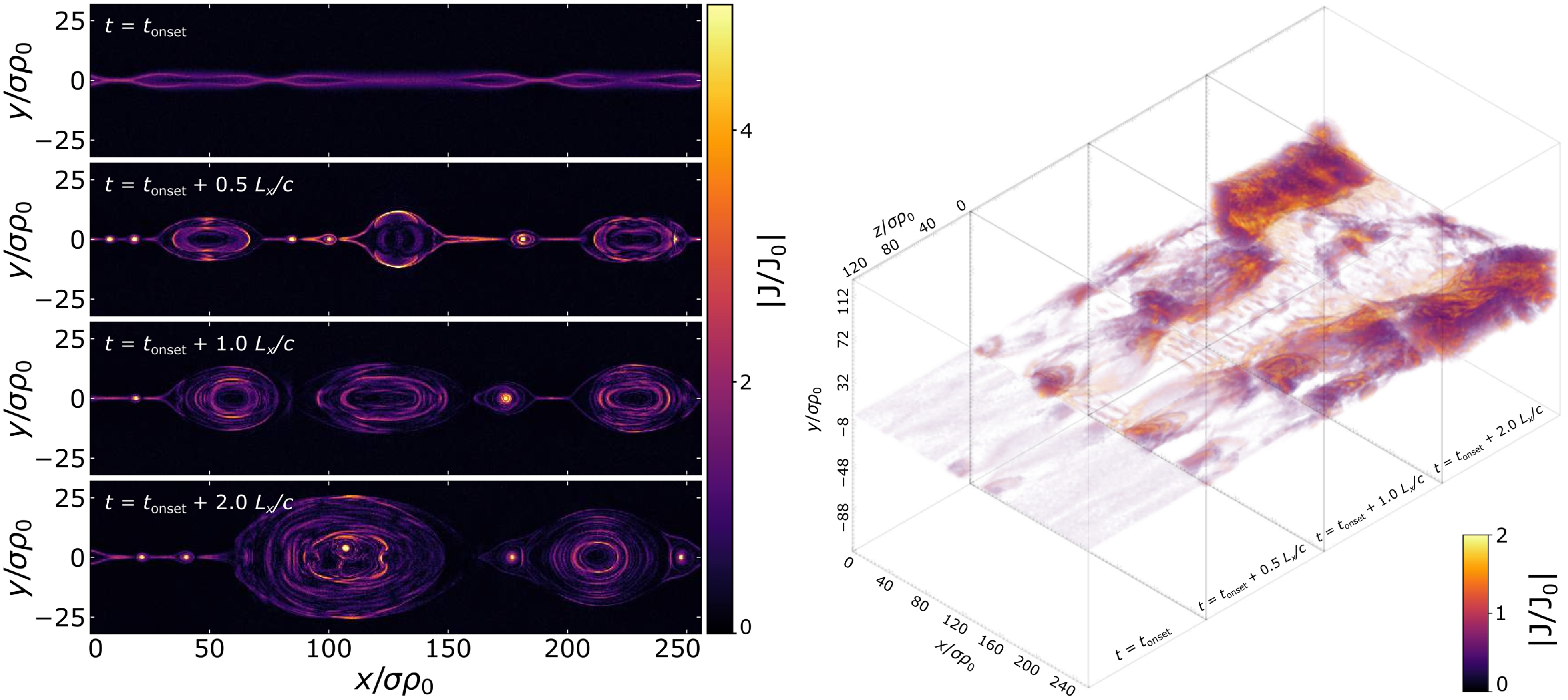
The earliest time displayed is the reconnection onset time $t_{\textrm {onset}}$
, defined as when the magnetic energy drops to
$t_{\textrm {onset}}$
, defined as when the magnetic energy drops to $99.99\,\%$
of its initial value. This threshold is sufficient for
$99.99\,\%$
of its initial value. This threshold is sufficient for $t_{\textrm {onset}}$
to demarcate the very first X-point collapse. Henceforth we will shift to this time for time-dependent results.
$t_{\textrm {onset}}$
to demarcate the very first X-point collapse. Henceforth we will shift to this time for time-dependent results.
Accordingly, initial X-point collapse in two dimensions is shown to coincide with $t_{\textrm {onset}}$
in the top-left panel of figure 2. Soon thereafter, plasmoids are advected downstream (
$t_{\textrm {onset}}$
in the top-left panel of figure 2. Soon thereafter, plasmoids are advected downstream ( $t_{\textrm {onset}} + 0.5 \,L_x/c$
), merge with other plasmoids (
$t_{\textrm {onset}} + 0.5 \,L_x/c$
), merge with other plasmoids ( $t_{\textrm {onset}} + 1.0 \,L_x/c$
) and retain their structural integrity throughout (
$t_{\textrm {onset}} + 1.0 \,L_x/c$
) and retain their structural integrity throughout ( $t_{\textrm {onset}} + 2.0 \,L_x/c$
). By contrast, in three dimensions the flux-rope kink instability dismantles plasmoids, allowing particles to escape from them (Dahlin et al. Reference Dahlin, Drake and Swisdak2014; Werner & Uzdensky Reference Werner and Uzdensky2021; Zhang et al. Reference Zhang, Guo, Daughton, Li and Li2021).
$t_{\textrm {onset}} + 2.0 \,L_x/c$
). By contrast, in three dimensions the flux-rope kink instability dismantles plasmoids, allowing particles to escape from them (Dahlin et al. Reference Dahlin, Drake and Swisdak2014; Werner & Uzdensky Reference Werner and Uzdensky2021; Zhang et al. Reference Zhang, Guo, Daughton, Li and Li2021).
4.1. Reconnection rate
We define the dimensionless time-dependent reconnection rate $\eta _{\textrm {rec}}(t)$
as the rate at which the unreconnected (i.e. upstream) magnetic flux
$\eta _{\textrm {rec}}(t)$
as the rate at which the unreconnected (i.e. upstream) magnetic flux $\psi _{\textrm {up}}$
decays with time, normalised by
$\psi _{\textrm {up}}$
decays with time, normalised by $v_{\textrm {A0}} B_0$
 \begin{equation} \eta _{\textrm {rec}}(t) \equiv -\frac {1}{v_{\textrm {A0}} B_0} \left \langle {\frac {\partial \psi _{\textrm {up}}}{\partial t}}\right \rangle , \ \psi _{\textrm {up}}(t) \equiv \frac {1}{L_x L_z} \int _{\textrm {up}} B_x(t) \,{\rm d}V, \ v_{\textrm {A0}} \equiv c \sqrt {\frac {\sigma }{1 + \sigma }}, \end{equation}
where $\langle {}\rangle$
is the time averaging performed every
$\langle {}\rangle$
is the time averaging performed every $(1/32) \, L_x/c$
and the upstream region is defined by cells with a mixing fraction
$(1/32) \, L_x/c$
and the upstream region is defined by cells with a mixing fraction $\lvert \mathcal{F}_e \rvert \gt 70\,\%$
(
$\lvert \mathcal{F}_e \rvert \gt 70\,\%$
( $96\,\%$
) in three dimensions (two dimensions). The peak reconnection rate is defined simply as
$96\,\%$
) in three dimensions (two dimensions). The peak reconnection rate is defined simply as $\text{max}[\eta _{\textrm {rec}}(t)]$
.
$\text{max}[\eta _{\textrm {rec}}(t)]$
.
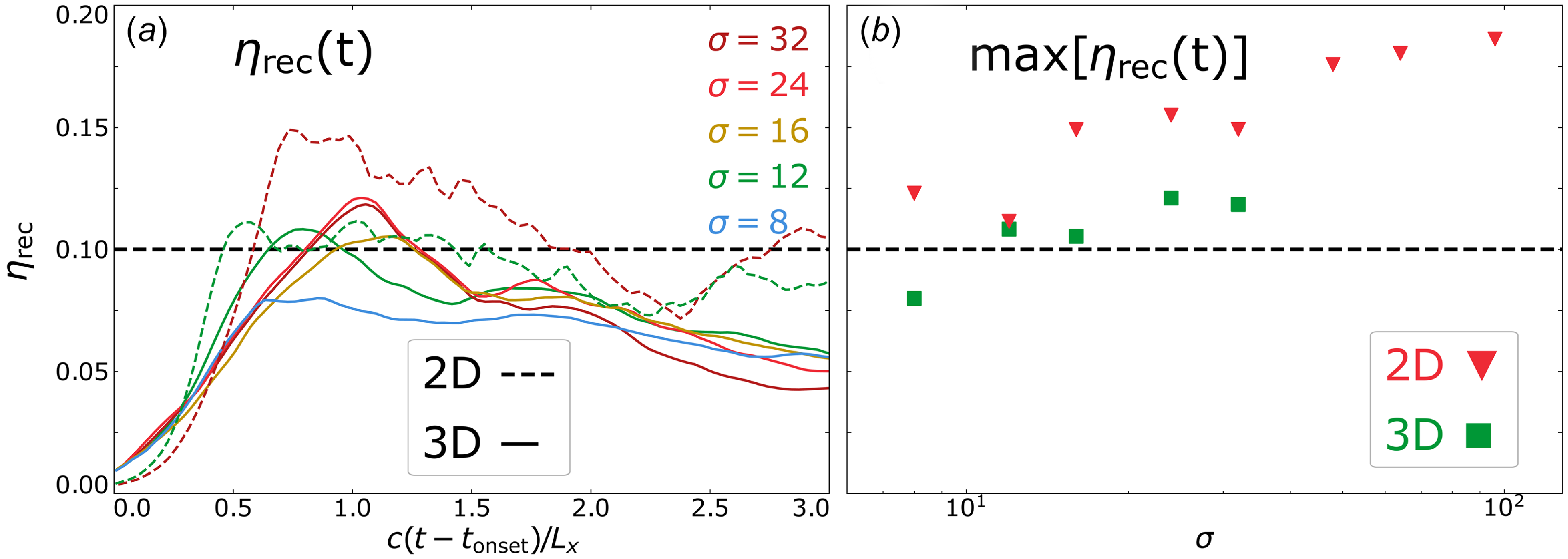
In accordance with (4.1), we compute the time-dependent and peak reconnection rates for several values of $\sigma$
, as shown in figure 3. We find that the reconnection rate in three dimensions is consistently somewhat lower than each 2-D counterpart for every tested value of
$\sigma$
, as shown in figure 3. We find that the reconnection rate in three dimensions is consistently somewhat lower than each 2-D counterpart for every tested value of $\sigma$
, and adheres quite closely to the canonical value of
$\sigma$
, and adheres quite closely to the canonical value of $0.1$
. As for
$0.1$
. As for $\sigma$
-dependence, the peak reconnection rate
$\sigma$
-dependence, the peak reconnection rate $\text{max}[\eta _{\textrm {rec}}(t)]$
increases gradually with increasing
$\text{max}[\eta _{\textrm {rec}}(t)]$
increases gradually with increasing $\sigma$
, from
$\sigma$
, from ${\simeq} 0.1$
to
${\simeq} 0.1$
to $0.2$
in two dimensions as
$0.2$
in two dimensions as $\sigma$
varies from
$\sigma$
varies from $8$
to
$8$
to $96$
and from
$96$
and from ${\simeq} 0.08$
to
${\simeq} 0.08$
to $0.12$
in three dimensions as
$0.12$
in three dimensions as $\sigma$
varies from
$\sigma$
varies from $8$
to
$8$
to $32$
.
$32$
.
Reconnection rates for various $\sigma$
. (a) Time-dependent reconnection rates of 3-D (solid) and a few 2-D (dashed) simulations. (b) Peak reconnection rates, with green squares representing three dimensions and red triangles representing two dimensions.
$\sigma$
. (a) Time-dependent reconnection rates of 3-D (solid) and a few 2-D (dashed) simulations. (b) Peak reconnection rates, with green squares representing three dimensions and red triangles representing two dimensions.
4.2. Injection energies
To fit particle spectra, we perform a spectral fitting procedure described in Appendix B. To illustrate the process for acquiring the characteristic spectral parameters, we show a time-evolved downstream particle spectrum $f_{\textrm {ds}}(\gamma - 1, t)$
in figure 4(a). The downstream particle population is continuously fed by upstream particles crossing over the separatrix.
$f_{\textrm {ds}}(\gamma - 1, t)$
in figure 4(a). The downstream particle population is continuously fed by upstream particles crossing over the separatrix.
Downstream particle spectra from 3-D simulations. (a) Evolving downstream particle spectrum from a $\sigma =32$
3-D simulation fitted at the final time step. The vertical dashed green line indicates the measured injection energy
$\sigma =32$
3-D simulation fitted at the final time step. The vertical dashed green line indicates the measured injection energy $\gamma _{\textrm {inj}}$
, the vertical dashed red line the measured cutoff energy
$\gamma _{\textrm {inj}}$
, the vertical dashed red line the measured cutoff energy $\gamma _c$
, and the dashed black line is
$\gamma _c$
, and the dashed black line is $\gamma ^{-p}$
with measured power-law index
$\gamma ^{-p}$
with measured power-law index $p$
. Solid colour lines show particle spectra taken every
$p$
. Solid colour lines show particle spectra taken every $(1/8) \, L_x/c$
, from
$(1/8) \, L_x/c$
, from $t = t_{\textrm {onset}}$
to
$t = t_{\textrm {onset}}$
to $t = t_{\textrm {onset}} + 3\, L_x/c$
. (b) Downstream particle spectra of 3-D simulations at times
$t = t_{\textrm {onset}} + 3\, L_x/c$
. (b) Downstream particle spectra of 3-D simulations at times $t = t_{\textrm {onset}} + 3\, L_x/c$
for various initial upstream magnetisations
$t = t_{\textrm {onset}} + 3\, L_x/c$
for various initial upstream magnetisations $\sigma$
. Dashed black lines show
$\sigma$
. Dashed black lines show $\gamma ^{-p}$
for
$\gamma ^{-p}$
for $\gamma \in [\gamma _{\textrm {inj}}, \gamma _c]$
using the measured values of
$\gamma \in [\gamma _{\textrm {inj}}, \gamma _c]$
using the measured values of $p, \gamma _{\textrm {inj}}, \gamma _c$
and dotted vertical lines are coloured and positioned at
$p, \gamma _{\textrm {inj}}, \gamma _c$
and dotted vertical lines are coloured and positioned at $\sigma$
values.
$\sigma$
values.

Measuring the characteristic parameters $p, \gamma _{\textrm {inj}}, \gamma _c$
helps glean their dependencies on system parameters. In figure 4(b), we show several downstream particle spectra of 3-D simulations at the time
$p, \gamma _{\textrm {inj}}, \gamma _c$
helps glean their dependencies on system parameters. In figure 4(b), we show several downstream particle spectra of 3-D simulations at the time $t = t_{\textrm {onset}} + 3\, L_x/c$
for various values of
$t = t_{\textrm {onset}} + 3\, L_x/c$
for various values of $\sigma$
, as well as power-law fits that extend from the injection energy to the cutoff energy. This figure highlights the precision of measurement that is afforded by implementing the spectral fitting procedure described in Appendix B.
$\sigma$
, as well as power-law fits that extend from the injection energy to the cutoff energy. This figure highlights the precision of measurement that is afforded by implementing the spectral fitting procedure described in Appendix B.
In the left-hand panels of figure 5 we show the evolved characteristic parameters of the power-law particle spectra ( $p, \gamma _{\textrm {inj}}, \gamma _c$
) for various values of
$p, \gamma _{\textrm {inj}}, \gamma _c$
) for various values of $\sigma$
represented by curves of different colour. Data points are obtained every
$\sigma$
represented by curves of different colour. Data points are obtained every $(1/32) \, L_x/c$
using the fitting procedure described in Appendix B and we smooth the data with a moving time average of window size
$(1/32) \, L_x/c$
using the fitting procedure described in Appendix B and we smooth the data with a moving time average of window size $(3/32) \, L_x/c$
, i.e. where each value is replaced by the average of itself, its predecessor and its successor. In the right-hand panels of figure 5 we plot each measured parameter evaluated at
$(3/32) \, L_x/c$
, i.e. where each value is replaced by the average of itself, its predecessor and its successor. In the right-hand panels of figure 5 we plot each measured parameter evaluated at $t = t_{\textrm {onset}} + 3 \, L_x/c$
against
$t = t_{\textrm {onset}} + 3 \, L_x/c$
against $\sigma$
.
$\sigma$
.
Spectral parameters measured via fitting procedure (described in Appendix B) for various $\sigma$
at each time step for 3-D simulations (a, c, e) and at
$\sigma$
at each time step for 3-D simulations (a, c, e) and at $t = t_{\textrm {onset}} + 3\, L_x/c$
for all simulations (b, d, f). Dotted coloured lines in (a, c, e) indicate time steps where the power-law extent is short, i.e.
$t = t_{\textrm {onset}} + 3\, L_x/c$
for all simulations (b, d, f). Dotted coloured lines in (a, c, e) indicate time steps where the power-law extent is short, i.e. $\gamma _c/\gamma _{\textrm {inj}} \lt 10$
. In (b, d, f), red triangles are 2-D runs and green squares are 3-D runs. (a, b) Power-law indices
$\gamma _c/\gamma _{\textrm {inj}} \lt 10$
. In (b, d, f), red triangles are 2-D runs and green squares are 3-D runs. (a, b) Power-law indices $p(t)$
and
$p(t)$
and $p(t_{\textrm {onset}} + 3\,L_x/c)$
. (c, d): Injection energies
$p(t_{\textrm {onset}} + 3\,L_x/c)$
. (c, d): Injection energies $\gamma _{\textrm {inj}}(t)$
and
$\gamma _{\textrm {inj}}(t)$
and $\gamma _{\textrm {inj}}(t_{\textrm {onset}} + 3\,L_x/c)$
. The dashed black line in (d) shows linear scaling, assuming
$\gamma _{\textrm {inj}}(t_{\textrm {onset}} + 3\,L_x/c)$
. The dashed black line in (d) shows linear scaling, assuming $\gamma _{\textrm {inj}} = 1 + \sigma /4$
and the dashed purple line shows
$\gamma _{\textrm {inj}} = 1 + \sigma /4$
and the dashed purple line shows $\gamma _{\textrm {inj}} \simeq \sigma [ \sigma _h^{-1} \, (1 + b_g^2)/2 ]^{1/2}$
(i.e. (2.7)), derived in § 2.1. (e, f) High-energy cutoffs
$\gamma _{\textrm {inj}} \simeq \sigma [ \sigma _h^{-1} \, (1 + b_g^2)/2 ]^{1/2}$
(i.e. (2.7)), derived in § 2.1. (e, f) High-energy cutoffs $\gamma _c(t)$
and
$\gamma _c(t)$
and $\gamma _c(t_{\textrm {onset}} + 3\,L_x/c)$
. The semi-transparent dashed coloured lines in (e) show the fit from (4.2) and the green (red) dashed line in (f) shows it evaluated at
$\gamma _c(t_{\textrm {onset}} + 3\,L_x/c)$
. The semi-transparent dashed coloured lines in (e) show the fit from (4.2) and the green (red) dashed line in (f) shows it evaluated at $t_{\textrm {onset}} + 3\,L_x/c$
, i.e.
$t_{\textrm {onset}} + 3\,L_x/c$
, i.e. $\gamma _c(\sigma ) = 6\sqrt {3}\sigma$
in three dimensions (
$\gamma _c(\sigma ) = 6\sqrt {3}\sigma$
in three dimensions ( $\gamma _c(\sigma ) = 4\sqrt {3}\sigma$
in two dimensions).
$\gamma _c(\sigma ) = 4\sqrt {3}\sigma$
in two dimensions).
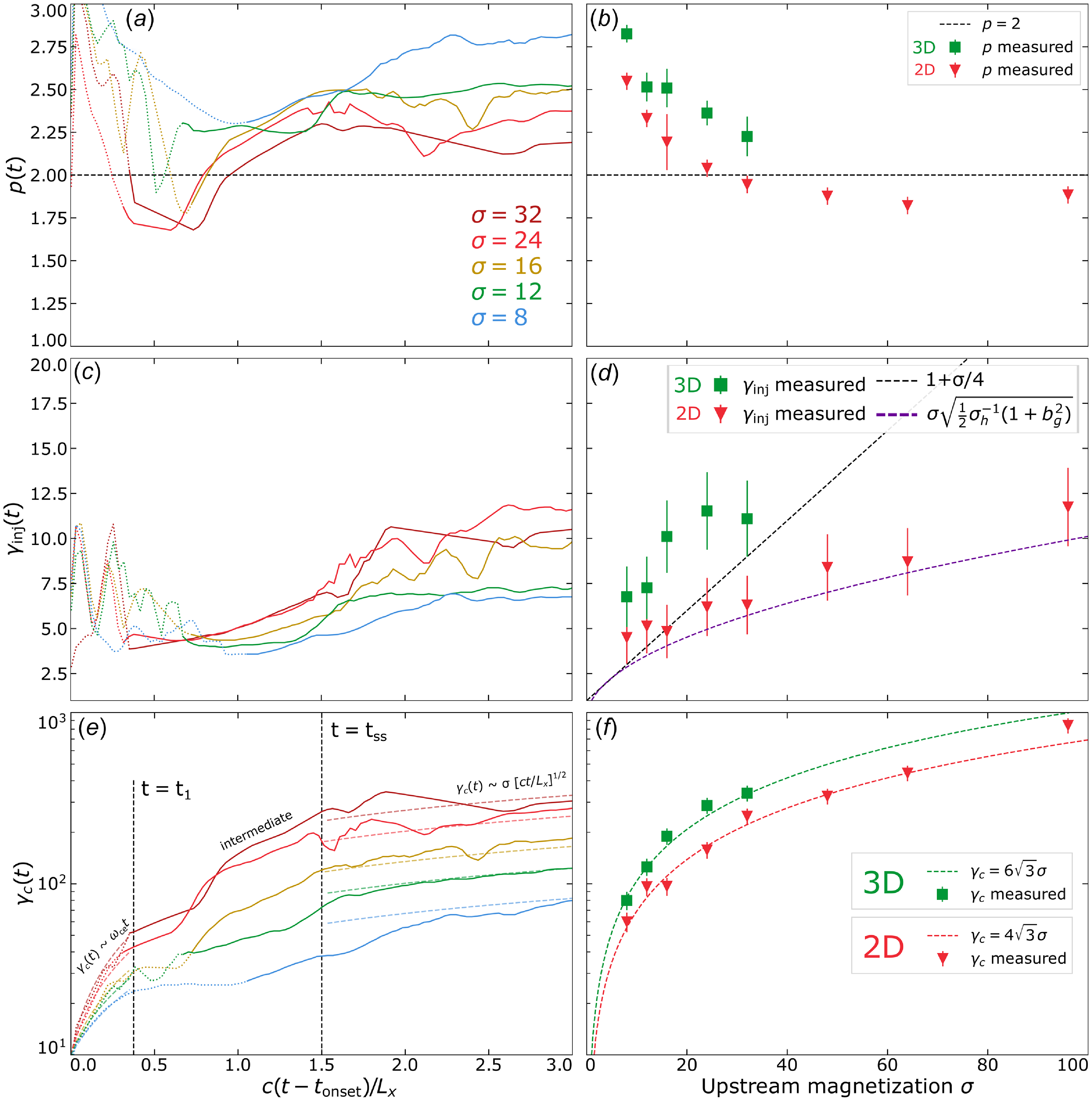
We find that power-law indices $p(t)$
(top row of figure 5) rapidly harden during the transient phase (
$p(t)$
(top row of figure 5) rapidly harden during the transient phase ( $t \lt t_1$
), followed by a longer period whereupon they gradually soften, achieving stability
$t \lt t_1$
), followed by a longer period whereupon they gradually soften, achieving stability ${\sim} 2$
light-crossing times after
${\sim} 2$
light-crossing times after $t_{\textrm {onset}}$
(panel a). Power-law spectra harden with increasing
$t_{\textrm {onset}}$
(panel a). Power-law spectra harden with increasing $\sigma$
and are harder in two dimensions than in three dimensions by
$\sigma$
and are harder in two dimensions than in three dimensions by ${\sim} 0.2$
–
${\sim} 0.2$
– $0.3$
for any given value of
$0.3$
for any given value of $\sigma$
(panel b).
$\sigma$
(panel b).
The injection energy $\gamma _{\textrm {inj}}(t)$
(middle row of figure 5) quickly adopts an initial (i.e. at
$\gamma _{\textrm {inj}}(t)$
(middle row of figure 5) quickly adopts an initial (i.e. at $t = t_{\textrm {onset}}$
) value of
$t = t_{\textrm {onset}}$
) value of ${\sim} 6 \pm 2$
without a clear dependence on
${\sim} 6 \pm 2$
without a clear dependence on $\sigma$
. While erratic, the injection energy remains roughly within this range during the transient reconnection phase (
$\sigma$
. While erratic, the injection energy remains roughly within this range during the transient reconnection phase ( $0 \leqslant t - t_{\textrm {onset}} \lt (3/8) \, L_x/c \simeq 100 \, \sigma \omega _{\textrm {ce}}^{-1}$
). Once steady state is reached (e.g. after
$0 \leqslant t - t_{\textrm {onset}} \lt (3/8) \, L_x/c \simeq 100 \, \sigma \omega _{\textrm {ce}}^{-1}$
). Once steady state is reached (e.g. after $1.5 \, L_x/c \simeq 400 \, \sigma \omega _{\textrm {ce}}^{-1}$
in three dimensions), the injection energy stabilises roughly on the same time scale with which
$1.5 \, L_x/c \simeq 400 \, \sigma \omega _{\textrm {ce}}^{-1}$
in three dimensions), the injection energy stabilises roughly on the same time scale with which $p(t)$
stabilises (panel c). At
$p(t)$
stabilises (panel c). At $t_{\textrm {onset}} + 3 \, L_x/c$
, the measured injection energies in two dimensions adhere reasonably closely to our model for the injection energy in the thermally dominated case
$t_{\textrm {onset}} + 3 \, L_x/c$
, the measured injection energies in two dimensions adhere reasonably closely to our model for the injection energy in the thermally dominated case $\gamma _{\textrm {inj}} \simeq \sigma [ \sigma _h^{-1} (1 + b_g^2)/2 ]^{1/2}$
(cf. (2.7)) (dashed purple line) and is greatly exceeded by the often-assumed linear relation of
$\gamma _{\textrm {inj}} \simeq \sigma [ \sigma _h^{-1} (1 + b_g^2)/2 ]^{1/2}$
(cf. (2.7)) (dashed purple line) and is greatly exceeded by the often-assumed linear relation of $\gamma _{\textrm {inj}} = \sigma /4$
(indicated by the dashed black line).
$\gamma _{\textrm {inj}} = \sigma /4$
(indicated by the dashed black line).
In three dimensions, injection energies are consistently greater by a factor of ${\sim} 1.5$
than in two dimensions, possibly owed to greater CS thicknesses at disruption in three dimensions vs two dimensions (cf. § 2.1). However, the large errors and the limited covered range of
${\sim} 1.5$
than in two dimensions, possibly owed to greater CS thicknesses at disruption in three dimensions vs two dimensions (cf. § 2.1). However, the large errors and the limited covered range of $\sigma$
makes a definite scaling trend difficult to decipher. We compare these results with previous work in § 5.1.
$\sigma$
makes a definite scaling trend difficult to decipher. We compare these results with previous work in § 5.1.
Although not the primary concern of this study, we measure the high-energy cutoff $\gamma _c$
to grow rapidly during the transient reconnection phase
$\gamma _c$
to grow rapidly during the transient reconnection phase $0 \leqslant t - t_{\textrm {onset}} \lesssim t_1 = (3/8) \, L_x/c \simeq 100 \, \sigma \omega _{\textrm {ce}}^{-1}$
, in both two and three dimensions. By assuming
$0 \leqslant t - t_{\textrm {onset}} \lesssim t_1 = (3/8) \, L_x/c \simeq 100 \, \sigma \omega _{\textrm {ce}}^{-1}$
, in both two and three dimensions. By assuming $\gamma _c(t)$
to scale with
$\gamma _c(t)$
to scale with $W_{\textrm {direct}}(t) \sim \eta _{\textrm {rec}} \omega _{\textrm {ce}} t$
, we apply the fit
$W_{\textrm {direct}}(t) \sim \eta _{\textrm {rec}} \omega _{\textrm {ce}} t$
, we apply the fit $\gamma _c(t) = a \, \omega _{\textrm {ce}} (t - t_{\textrm {onset}})$
, where
$\gamma _c(t) = a \, \omega _{\textrm {ce}} (t - t_{\textrm {onset}})$
, where $a$
is a fitting parameter. Performing this fit in three dimensions yields the coefficients
$a$
is a fitting parameter. Performing this fit in three dimensions yields the coefficients $a = 0.020, 0.017, 0.015, 0.014, 0.014$
for
$a = 0.020, 0.017, 0.015, 0.014, 0.014$
for $\sigma = 8, 12, 16, 24, 32$
. The sensitivity of
$\sigma = 8, 12, 16, 24, 32$
. The sensitivity of $a$
to
$a$
to $\sigma$
declines as the
$\sigma$
declines as the $\sigma \gg 1$
regime is entered. These fits are plotted on figure 5(e).
$\sigma \gg 1$
regime is entered. These fits are plotted on figure 5(e).
The steady-state phase ( $t - t_{\textrm {onset}} \geqslant t_{\textrm {ss}}$
, where
$t - t_{\textrm {onset}} \geqslant t_{\textrm {ss}}$
, where $t_{\textrm {ss}}$
is the steady-state time) is characterised by the time interval when the simulation domain is populated with multiple plasmoids and the cutoff grows steadily. In three dimensions, the transition from the transient to the steady-state phase takes
$t_{\textrm {ss}}$
is the steady-state time) is characterised by the time interval when the simulation domain is populated with multiple plasmoids and the cutoff grows steadily. In three dimensions, the transition from the transient to the steady-state phase takes ${\sim}1 \, L_x/c$
to complete for
${\sim}1 \, L_x/c$
to complete for $\sigma \gg 1$
, with longer transition times at moderate values of
$\sigma \gg 1$
, with longer transition times at moderate values of $\sigma$
(cf.
$\sigma$
(cf. $\sigma = 8, 12$
). Thus
$\sigma = 8, 12$
). Thus $t_{\textrm {ss}} = t_{\textrm {onset}} + 1.5 L_x/c \simeq t_{\textrm {onset}} + 400 \, \sigma \omega _{\textrm {ce}}^{-1}$
. During the steady-state phase (
$t_{\textrm {ss}} = t_{\textrm {onset}} + 1.5 L_x/c \simeq t_{\textrm {onset}} + 400 \, \sigma \omega _{\textrm {ce}}^{-1}$
. During the steady-state phase ( $t \gt t_{\textrm {ss}}$
),
$t \gt t_{\textrm {ss}}$
), $\gamma _c(t)$
is fitted reasonably well by
$\gamma _c(t)$
is fitted reasonably well by $\gamma _c(t) = 6 \sigma [ c(t - t_{\textrm {onset}})/L_x ]^{1/2}$
for every value of
$\gamma _c(t) = 6 \sigma [ c(t - t_{\textrm {onset}})/L_x ]^{1/2}$
for every value of $\sigma$
in three dimensions (panel e). Thus the complete cutoff energy fit in three dimensions is (where
$\sigma$
in three dimensions (panel e). Thus the complete cutoff energy fit in three dimensions is (where $a \simeq 0.014$
in the
$a \simeq 0.014$
in the $\sigma \gg 1$
limit)
$\sigma \gg 1$
limit)
 \begin{equation} \gamma _c(t) = \begin{cases} a \, \omega _{\textrm {ce}}(t - t_{\textrm {onset}}) & 0 \leqslant t - t_{\textrm {onset}} \lt t_1 ,\\ \text{intermediate} & t_1 \leqslant t - t_{\textrm {onset}} \lt t_{\textrm {ss}} ,\\ 6 \sigma \big [ c(t - t_{\textrm {onset}})/L_x \big ]^{1/2} & t - t_{\textrm {onset}} \geqslant t_{\textrm {ss}} .\end{cases} \end{equation}
By contrast, in two dimensions the transition from transient to steady-state is much more sudden (not shown). The complete cutoff energy fit in two dimensions is (where $a \simeq 0.014$
in the
$a \simeq 0.014$
in the $\sigma \gg 1$
limit)
$\sigma \gg 1$
limit)
 \begin{equation} \gamma _c(t) = \begin{cases} a \, \omega _{\textrm {ce}}(t - t_{\textrm {onset}}) & 0 \leqslant t - t_{\textrm {onset}} \lt t_1 \simeq t_{\textrm {ss}} ,\\ 4 \sigma \big [ c(t - t_{\textrm {onset}})/L_x \big ]^{1/2} & t - t_{\textrm {onset}} \geqslant t_{\textrm {ss}}. \end{cases} \end{equation}
We also explicitly measure the high-energy cutoff at $t = t_{\textrm {onset}} + 3 \, L_x/c$
and find that it indeed adheres well to a linear scaling with
$t = t_{\textrm {onset}} + 3 \, L_x/c$
and find that it indeed adheres well to a linear scaling with $\sigma$
(panel f). We discuss the coefficient
$\sigma$
(panel f). We discuss the coefficient $a$
and comparisons with previous work in § 5.3.
$a$
and comparisons with previous work in § 5.3.
4.3. Injection efficiencies
To contextualise the injection shares in the broader downstream population, we compute the injection (or number) efficiency, defined by
 \begin{equation} \eta _{N}(t) \equiv N_{\textrm {inj}}(t)/N_{\textrm {ds}}(t), \ N_{\textrm {inj}}(t) \equiv \int _{\gamma _{\textrm {inj}}(t)}^\infty f_{\textrm {ds}}(\gamma , t) \,\text{d}\gamma , \ N_{\textrm {ds}}(t) \equiv \int _1^\infty f_{\textrm {ds}}(\gamma , t) \,\text{d}\gamma , \end{equation}
and the energy efficiency, defined by
 \begin{equation} \eta _{E}(t) \equiv E_{\textrm {inj}}(t)/E_{\textrm {ds}}(t), \ E_{\textrm {inj}}(t) \equiv \int _{\gamma _{\textrm {inj}}(t)}^\infty \gamma f_{\textrm {ds}}(\gamma , t) \,\text{d}\gamma , \ E_{\textrm {ds}}(t) \equiv \int _1^\infty \gamma f_{\textrm {ds}}(\gamma , t) \,\text{d}\gamma . \end{equation}
Since these quantities depend on $\gamma _{\textrm {inj}}(t)$
measured from time-evolving particle spectra, these efficiencies are well defined for
$\gamma _{\textrm {inj}}(t)$
measured from time-evolving particle spectra, these efficiencies are well defined for $t \gt t_{\textrm {onset}}$
, i.e. when power-law spectra may be deciphered by our spectrum fitting procedure.
$t \gt t_{\textrm {onset}}$
, i.e. when power-law spectra may be deciphered by our spectrum fitting procedure.
We use (4.4), (4.5) to directly compute $\eta _N(t)$
and
$\eta _N(t)$
and $\eta _E$
(t) for various
$\eta _E$
(t) for various $\sigma$
, as shown in figure 6.
$\sigma$
, as shown in figure 6.
Efficiencies of particle injection and energy computed for 3-D simulations at various $\sigma$
at each time step (a, c) and at final times (b, d), comparing 2-D (red triangle) and 3-D (green square) runs. Dotted segments in (a, c) indicate time steps for which the power-law extent was short (i.e.
$\sigma$
at each time step (a, c) and at final times (b, d), comparing 2-D (red triangle) and 3-D (green square) runs. Dotted segments in (a, c) indicate time steps for which the power-law extent was short (i.e. $t$
for which
$t$
for which $\gamma _c(t)/\gamma _{\textrm {inj}}(t) \lt 10$
), whereas solid lines indicate times where
$\gamma _c(t)/\gamma _{\textrm {inj}}(t) \lt 10$
), whereas solid lines indicate times where $\gamma _c(t)/\gamma _{\textrm {inj}}(t) \gt 10$
. (a, b) Injection efficiencies, where the dashed black horizontal line indicates
$\gamma _c(t)/\gamma _{\textrm {inj}}(t) \gt 10$
. (a, b) Injection efficiencies, where the dashed black horizontal line indicates $\eta _{N} = 40\,\%$
on (b). (c, d) Energy efficiencies, where the dashed black horizontal line indicates
$\eta _{N} = 40\,\%$
on (b). (c, d) Energy efficiencies, where the dashed black horizontal line indicates $\eta _{E} = 90\,\%$
in (d). Time-evolved errors are not shown but are comparable to the final-time errors.
$\eta _{E} = 90\,\%$
in (d). Time-evolved errors are not shown but are comparable to the final-time errors.
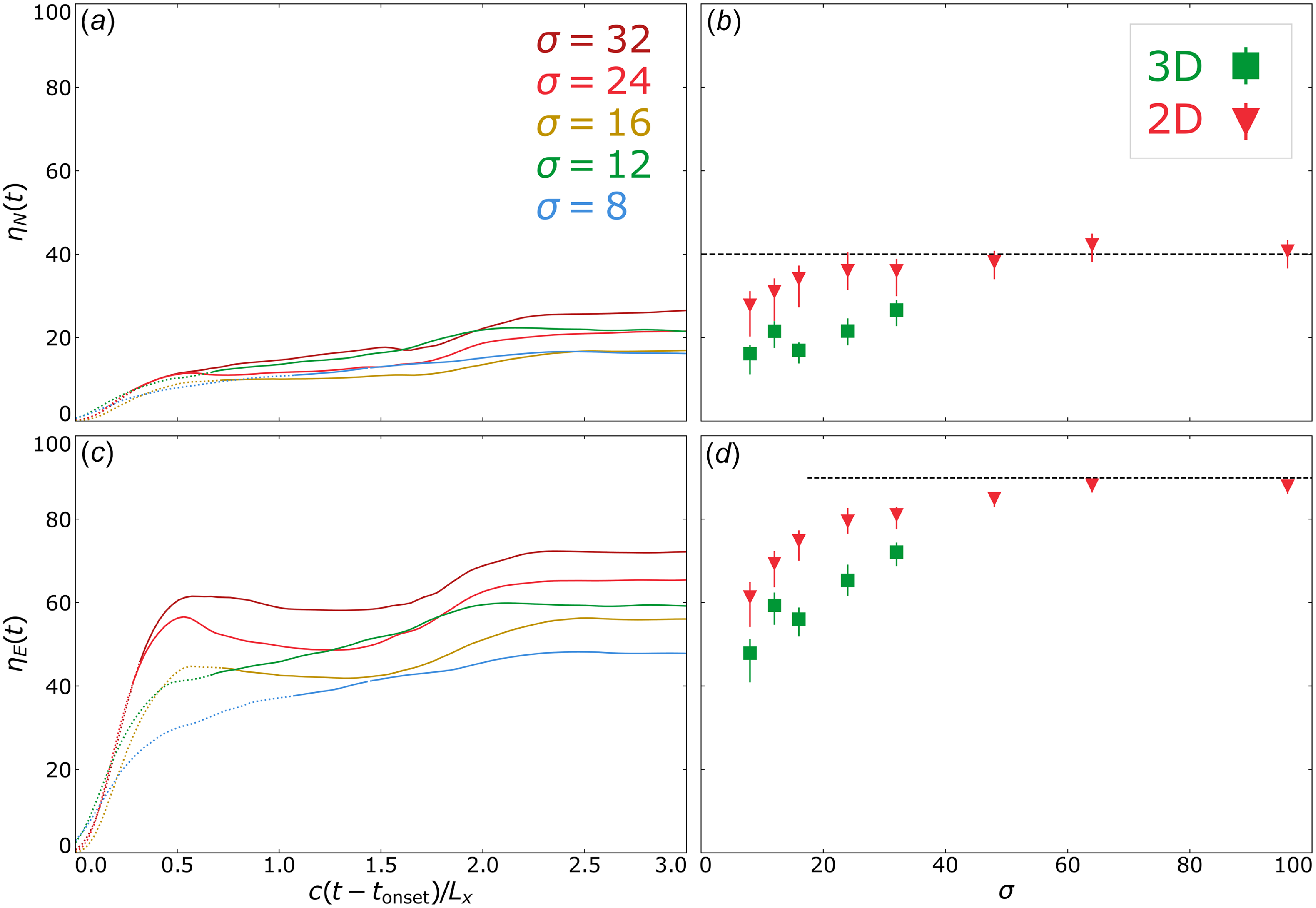
We generally find that both $\eta _N(t)$
(panel a) and
$\eta _N(t)$
(panel a) and $\eta _E(t)$
(panel c) display a period of rapid initial growth for approximately
$\eta _E(t)$
(panel c) display a period of rapid initial growth for approximately $0.5 \, L_x/c$
after
$0.5 \, L_x/c$
after $t_{\textrm {onset}}$
, slowing down significantly at intermediate times, eventually saturating at a finite
$t_{\textrm {onset}}$
, slowing down significantly at intermediate times, eventually saturating at a finite $\sigma$
-dependent values
$\sigma$
-dependent values $\eta _{N,\textrm {sat}}(\sigma )$
and
$\eta _{N,\textrm {sat}}(\sigma )$
and $\eta _{E,\textrm {sat}}(\sigma )$
at late times,
$\eta _{E,\textrm {sat}}(\sigma )$
at late times, $t-t_{\textrm {onset}} \gtrsim 2 \, L_x/c$
, in agreement with the slower late-time growth of
$t-t_{\textrm {onset}} \gtrsim 2 \, L_x/c$
, in agreement with the slower late-time growth of $\gamma _c(t)$
and stabilisation of
$\gamma _c(t)$
and stabilisation of $p(t)$
. In two dimensions, the time-saturated injection efficiency
$p(t)$
. In two dimensions, the time-saturated injection efficiency $\eta _{N,\textrm {sat}}$
improves from
$\eta _{N,\textrm {sat}}$
improves from ${\sim}30\,\%$
to
${\sim}30\,\%$
to ${\sim}40\,\%$
as
${\sim}40\,\%$
as $\sigma$
is increased from
$\sigma$
is increased from $8$
to
$8$
to $96$
, at which point convergence with
$96$
, at which point convergence with $\sigma$
is achieved (panel b). The 3-D simulations systematically show somewhat lower values of
$\sigma$
is achieved (panel b). The 3-D simulations systematically show somewhat lower values of $\eta _{N,\textrm {sat}}$
(20 %–25 %) than their 2-D counterparts for any given value of
$\eta _{N,\textrm {sat}}$
(20 %–25 %) than their 2-D counterparts for any given value of $\sigma$
, likely owed to softer power-law indices; cf. figure 5. However, because of the limited
$\sigma$
, likely owed to softer power-law indices; cf. figure 5. However, because of the limited $\sigma$
-range covered by our 3-D simulation campaign, it is difficult to extract any clear and reliable systematic trends for the dependence of
$\sigma$
-range covered by our 3-D simulation campaign, it is difficult to extract any clear and reliable systematic trends for the dependence of $\eta _{N,\textrm {sat}}$
on
$\eta _{N,\textrm {sat}}$
on $\sigma$
in three dimensions.
$\sigma$
in three dimensions.
The final saturated energy efficiency $\eta _{E,\textrm {sat}}(\sigma )$
in 2-D simulations also grows monotonically starting from
$\eta _{E,\textrm {sat}}(\sigma )$
in 2-D simulations also grows monotonically starting from ${\sim}60\,\%$ $\sigma =8$
and saturates at the
$\sigma =8$
and saturates at the ${\sim}90\,\%$
-level for
${\sim}90\,\%$
-level for $\sigma \gtrsim 50$
(panel d). In three dimensions,
$\sigma \gtrsim 50$
(panel d). In three dimensions, $\eta _{E,\textrm {sat}}(\sigma )$
is again lower than in two dimensions, but, unlike
$\eta _{E,\textrm {sat}}(\sigma )$
is again lower than in two dimensions, but, unlike $\eta _{N,\textrm {sat}}(\sigma )$
, exhibits clear monotonic growth with
$\eta _{N,\textrm {sat}}(\sigma )$
, exhibits clear monotonic growth with $\sigma$
, exceeding 70 % at the highest probed value
$\sigma$
, exceeding 70 % at the highest probed value $\sigma =32$
. Extending our 3-D study to even higher values of
$\sigma =32$
. Extending our 3-D study to even higher values of $\sigma$
is clearly needed in order to determine how and what level
$\sigma$
is clearly needed in order to determine how and what level $\eta _{E,\textrm {sat}}(\sigma )$
saturates in the ultra-relativistic limit
$\eta _{E,\textrm {sat}}(\sigma )$
saturates in the ultra-relativistic limit $\sigma \to \infty$
.
$\sigma \to \infty$
.
In summary, the time-converged injection and energy efficiencies become high ( $\eta _N \simeq 40\,\%$
,
$\eta _N \simeq 40\,\%$
, $\eta _E \simeq 90\,\%$
) in two dimensions and are insensitive to
$\eta _E \simeq 90\,\%$
) in two dimensions and are insensitive to $\sigma$
once it is sufficiently great. While these efficiencies are systematically lower in three dimensions likely due to softer power-law indices, they are not yet converged at
$\sigma$
once it is sufficiently great. While these efficiencies are systematically lower in three dimensions likely due to softer power-law indices, they are not yet converged at $\sigma = 32$
.
$\sigma = 32$
.
4.4. Injection shares
To obtain the time-evolved contribution of each injection mechanism (see § 2.2) to the total population of injected particles, we apply the formula
 \begin{equation} \mathcal{S}_i(t) \equiv \frac {\mathcal{N}^{\textrm {inj}}_i(t)}{\sum _j \mathcal{N}^{\textrm {inj}}_j(t)}, \end{equation}
where $\mathcal{N}^{\textrm {inj}}_i(t)$
is the cumulative number of particles injected by mechanism
$\mathcal{N}^{\textrm {inj}}_i(t)$
is the cumulative number of particles injected by mechanism $i$
at time
$i$
at time $t$
. We term these
$t$
. We term these $\mathcal{S}_i(t)$
’s ‘injection shares’ and plot them in figure 7 against
$\mathcal{S}_i(t)$
’s ‘injection shares’ and plot them in figure 7 against $c(t-\tau _{\textrm {inj}})/L_x$
, where
$c(t-\tau _{\textrm {inj}})/L_x$
, where $\tau _{\textrm {inj}} \gtrsim t_{\textrm {onset}}$
is the moment when the first injection of a tracer particle occurs.
$\tau _{\textrm {inj}} \gtrsim t_{\textrm {onset}}$
is the moment when the first injection of a tracer particle occurs.
In panel (a), we show time-evolved injection shares for 3-D simulations for the scanned values of $\sigma$
. Here, we find a specific activation sequence of the injection mechanisms that is consistent with our conceptual picture of injection in figure 1. Soon after
$\sigma$
. Here, we find a specific activation sequence of the injection mechanisms that is consistent with our conceptual picture of injection in figure 1. Soon after $t_{\textrm {onset}}$
, the
$t_{\textrm {onset}}$
, the $W_{\textrm {direct}}$
share is at
$W_{\textrm {direct}}$
share is at $100\,\%$
. At
$100\,\%$
. At $t \simeq \tau _{\textrm {inj}} + 0.25 \, L_x/c$
, Fermi kicks are activated and gradually (over
$t \simeq \tau _{\textrm {inj}} + 0.25 \, L_x/c$
, Fermi kicks are activated and gradually (over $1 \, L_x/c$
) become the dominant injection mechanism (except for
$1 \, L_x/c$
) become the dominant injection mechanism (except for $\sigma = 8$
, where the pickup process takes a significant
$\sigma = 8$
, where the pickup process takes a significant ${\sim}20\,\%$
fraction). Finally, at
${\sim}20\,\%$
fraction). Finally, at $t \simeq \tau _{\textrm {inj}} + 0.5 \, L_x/c$
, particles start getting injected by the pickup mechanism, roughly coincident with the time when reconnection outflows are established. The time intervals between the activation of each subsequent mechanism appear independent of
$t \simeq \tau _{\textrm {inj}} + 0.5 \, L_x/c$
, particles start getting injected by the pickup mechanism, roughly coincident with the time when reconnection outflows are established. The time intervals between the activation of each subsequent mechanism appear independent of $\sigma$
. While not shown in this figure, we also calculate the fraction of injected particles that are injected at these activation times: at
$\sigma$
. While not shown in this figure, we also calculate the fraction of injected particles that are injected at these activation times: at $c(t - \tau _{\textrm {inj}})/L_x = 0.25, 0.5, 1$
, only
$c(t - \tau _{\textrm {inj}})/L_x = 0.25, 0.5, 1$
, only ${\sim}1/1000$
,
${\sim}1/1000$
, ${\sim}1/100$
and
${\sim}1/100$
and ${\sim}1/10$
of particles that end up injected by
${\sim}1/10$
of particles that end up injected by $t = \tau _{\textrm {inj}} + 2 \, L_x/c$
have been injected. This shows that the early dominance of direct acceleration may be misleading, since it represents
$t = \tau _{\textrm {inj}} + 2 \, L_x/c$
have been injected. This shows that the early dominance of direct acceleration may be misleading, since it represents $\lt 10\,\%$
of the aggregate population of injected particles.
$\lt 10\,\%$
of the aggregate population of injected particles.
Contributions of each injection mechanism to the injected particle population. (a) Time-evolved injection shares from 3-D runs for several values of $\sigma$
. (b) Injection shares over all runs at
$\sigma$
. (b) Injection shares over all runs at $t = \tau _{\textrm {inj}} + 2\, L_x/c$
. All injection shares have an error of
$t = \tau _{\textrm {inj}} + 2\, L_x/c$
. All injection shares have an error of ${\sim}3\,\%$
for each mechanism at every time step, propagated from errors of
${\sim}3\,\%$
for each mechanism at every time step, propagated from errors of $\gamma _{\textrm {inj}}$
.
$\gamma _{\textrm {inj}}$
.
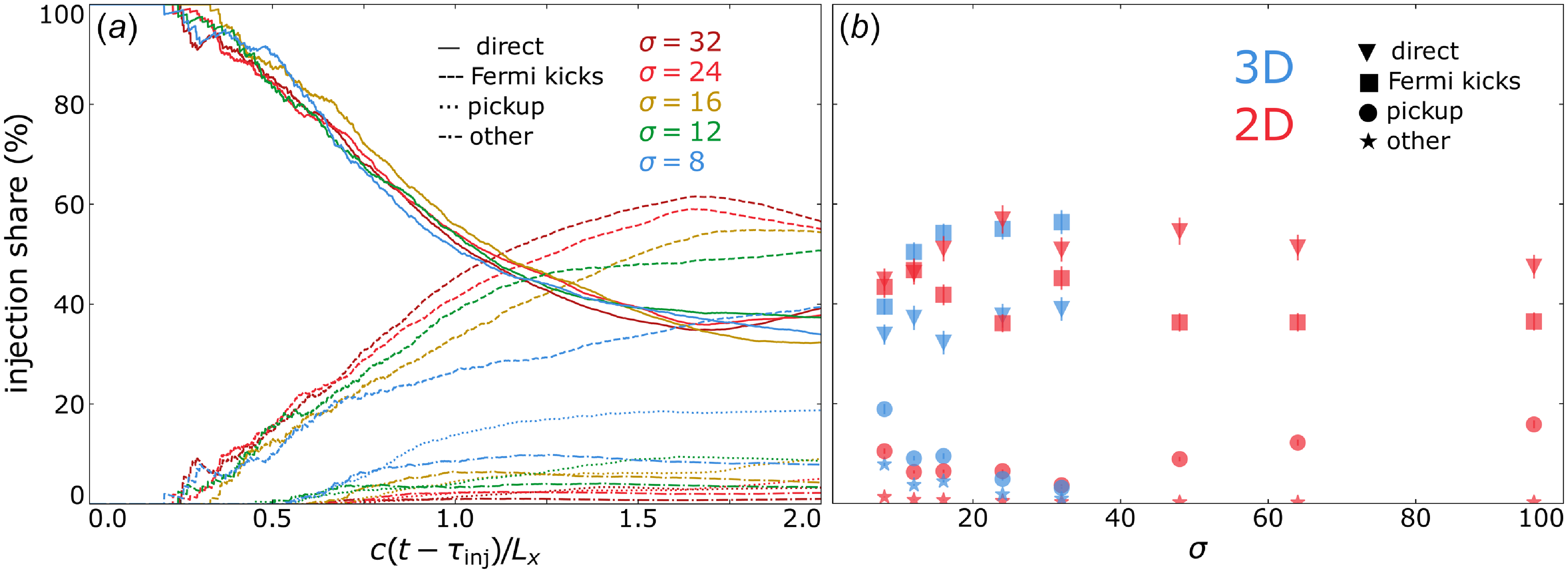
In panel (b), we plot the injection shares at $t = t_{\textrm {onset}} + 2\, L_x/c$
against
$t = t_{\textrm {onset}} + 2\, L_x/c$
against $\sigma$
for 2-D and 3-D simulations. We find that injections by Fermi and direct acceleration remain competitive: Aside from
$\sigma$
for 2-D and 3-D simulations. We find that injections by Fermi and direct acceleration remain competitive: Aside from $\sigma = 8$
, we find in three dimensions that Fermi kicks contribute
$\sigma = 8$
, we find in three dimensions that Fermi kicks contribute ${\sim}50\,\%$
whereas direct acceleration contributes
${\sim}50\,\%$
whereas direct acceleration contributes ${\sim}40\,\%$
, and that these shares are flipped in two dimensions. Meanwhile, when increasing
${\sim}40\,\%$
, and that these shares are flipped in two dimensions. Meanwhile, when increasing $\sigma$
from
$\sigma$
from $8$
to
$8$
to $32$
, we find that pickup shares are suppressed significantly, from
$32$
, we find that pickup shares are suppressed significantly, from $20\,\%$
(
$20\,\%$
( $10\,\%$
)
$10\,\%$
) $\to 5\,\%$
in three dimensions (two dimensions); however, they curiously rise back up in two dimensions when varying
$\to 5\,\%$
in three dimensions (two dimensions); however, they curiously rise back up in two dimensions when varying $\sigma$
from
$\sigma$
from $48$
to
$48$
to $96$
. A negligible (
$96$
. A negligible ( ${\sim}1 \,\%$
) fraction of particles satisfy
${\sim}1 \,\%$
) fraction of particles satisfy $(W_\parallel \gt W_\perp ) \, \& \, (\lvert \boldsymbol{p}_\perp ' \rvert \gt \lvert \boldsymbol{p}_\parallel \rvert )$
upon reaching the injection energy
$(W_\parallel \gt W_\perp ) \, \& \, (\lvert \boldsymbol{p}_\perp ' \rvert \gt \lvert \boldsymbol{p}_\parallel \rvert )$
upon reaching the injection energy $\gamma _{\textrm {inj}}$
(categorised as ‘other’ in § 2.2), suggesting that any mechanisms which impart this combination onto particles can be ignored.
$\gamma _{\textrm {inj}}$
(categorised as ‘other’ in § 2.2), suggesting that any mechanisms which impart this combination onto particles can be ignored.
4.5. Non-thermal particle acceleration (NTPA) correlations of each mechanism
Given a particle of energy $\gamma \geqslant \gamma _{\textrm {inj}}$
, what is the probability that it was injected by the mechanism
$\gamma \geqslant \gamma _{\textrm {inj}}$
, what is the probability that it was injected by the mechanism $\mathcal{M}_i$
? In other words, to what extent is each injection mechanism likely, by mere correlation, to produce particles of a given energy
$\mathcal{M}_i$
? In other words, to what extent is each injection mechanism likely, by mere correlation, to produce particles of a given energy $\gamma$
(e.g.
$\gamma$
(e.g. $\gamma \gg \gamma _{\textrm {inj}}$
)? We attempt to answer this question by introducing the ‘NTPA correlation’
$\gamma \gg \gamma _{\textrm {inj}}$
)? We attempt to answer this question by introducing the ‘NTPA correlation’ $\mathcal{C}_i$
of each injection mechanism
$\mathcal{C}_i$
of each injection mechanism $\mathcal{M}_i$
, defined by
$\mathcal{M}_i$
, defined by
 \begin{equation} \mathcal{C}_i (\gamma ) \equiv \frac {\mathcal{N}_i(\gamma , \tau )}{\sum _i \mathcal{N}_i (\gamma , \tau )}, \end{equation}
where $\mathcal{N}_i(\gamma , \tau )$
is the number of particles injected by mechanism
$\mathcal{N}_i(\gamma , \tau )$
is the number of particles injected by mechanism $\mathcal{M}_i$
with energy
$\mathcal{M}_i$
with energy $\gamma \geqslant \gamma _{\textrm {inj}}$
at a certain time
$\gamma \geqslant \gamma _{\textrm {inj}}$
at a certain time $\tau$
that will be taken to be
$\tau$
that will be taken to be $\tau = \tau _{\textrm {inj}} + 2\, L_x/c$
. We term these quantities ‘correlations’ to emphasise that the
$\tau = \tau _{\textrm {inj}} + 2\, L_x/c$
. We term these quantities ‘correlations’ to emphasise that the $\mathcal{C}_i$
values merely represent the correlation between high-energy particles and their injection mechanism of origin.
$\mathcal{C}_i$
values merely represent the correlation between high-energy particles and their injection mechanism of origin.
To calculate $\mathcal{C}_i(\gamma )$
, we define
$\mathcal{C}_i(\gamma )$
, we define $\lfloor 5\, \gamma _c/\gamma _{\textrm {inj}} \rfloor$
(i.e. rounded to the nearest integer below
$\lfloor 5\, \gamma _c/\gamma _{\textrm {inj}} \rfloor$
(i.e. rounded to the nearest integer below $5\, \gamma _c/\gamma _{\textrm {inj}}$
) energy bins for
$5\, \gamma _c/\gamma _{\textrm {inj}}$
) energy bins for $\gamma \in [\gamma _{\textrm {inj}}, \gamma _c]$
spaced uniformly in log space. Then, we populate these bins with the final energies particles attain, sorted by which mechanism injected them; this yields
$\gamma \in [\gamma _{\textrm {inj}}, \gamma _c]$
spaced uniformly in log space. Then, we populate these bins with the final energies particles attain, sorted by which mechanism injected them; this yields $\mathcal{N}_i(\gamma , \tau )$
. Finally, we obtain
$\mathcal{N}_i(\gamma , \tau )$
. Finally, we obtain $\mathcal{C}_i(\gamma )$
by normalising each histogram by
$\mathcal{C}_i(\gamma )$
by normalising each histogram by $\sum _i \mathcal{N}_i (\gamma , \tau )$
, thereby ensuring that
$\sum _i \mathcal{N}_i (\gamma , \tau )$
, thereby ensuring that $\sum _i \mathcal{C}_i(\gamma ) = 100\,\%$
at each energy bin. In figure 8 we plot
$\sum _i \mathcal{C}_i(\gamma ) = 100\,\%$
at each energy bin. In figure 8 we plot $\mathcal{C}_i(\gamma )$
for each injection mechanism for
$\mathcal{C}_i(\gamma )$
for each injection mechanism for $\gamma \in [\gamma _{\textrm {inj}}, \gamma _c]$
.
$\gamma \in [\gamma _{\textrm {inj}}, \gamma _c]$
.
The NTPA correlation of each injection mechanism evaluated at $\tau = \tau _{\textrm {inj}} + 2\, L_x/c$
plotted against
$\tau = \tau _{\textrm {inj}} + 2\, L_x/c$
plotted against $\gamma - 1$
for
$\gamma - 1$
for $\gamma \in [\gamma _{\textrm {inj}}, \gamma _c]$
, with
$\gamma \in [\gamma _{\textrm {inj}}, \gamma _c]$
, with $\sigma$
values indicated by the vertical dashed lines. (a) The NTPA correlations of four 2-D simulations with
$\sigma$
values indicated by the vertical dashed lines. (a) The NTPA correlations of four 2-D simulations with $\sigma = 12, 24, 48, 96$
indicated by blue, green, gold and red lines, respectively. (b) The NTPA correlations of 2-D (red) and 3-D (green)
$\sigma = 12, 24, 48, 96$
indicated by blue, green, gold and red lines, respectively. (b) The NTPA correlations of 2-D (red) and 3-D (green) $\sigma = 12$
simulations.
$\sigma = 12$
simulations.
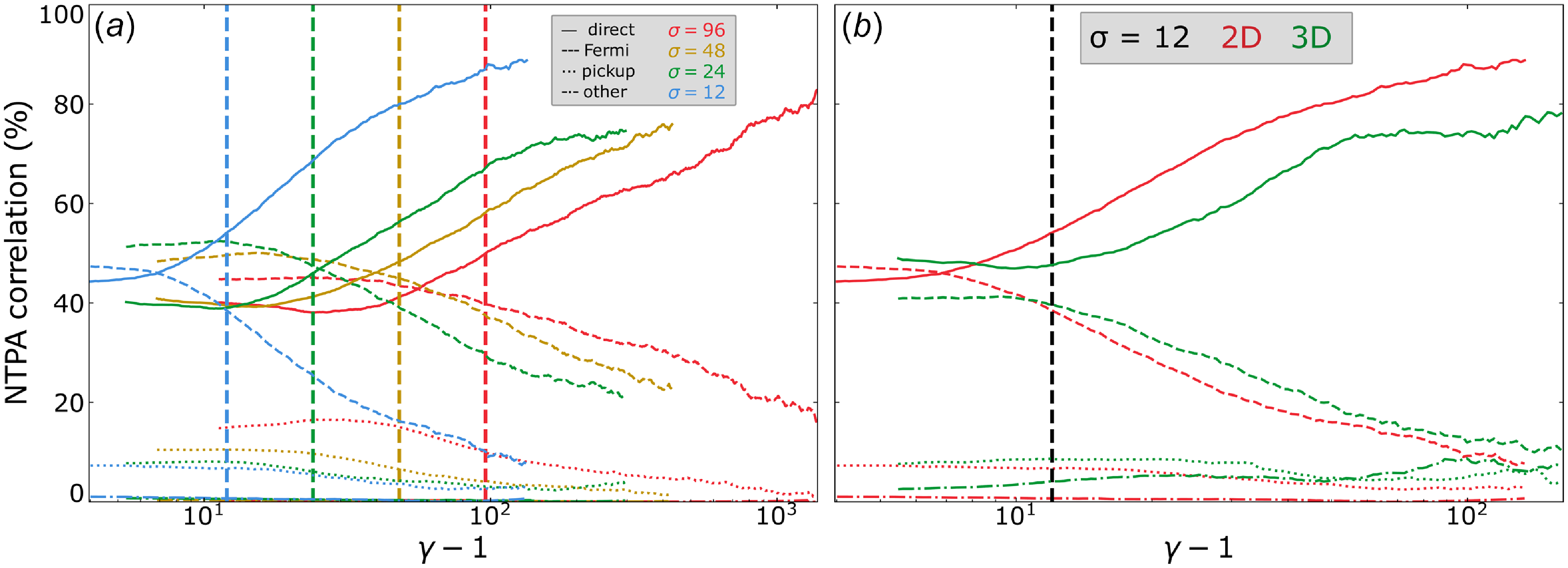
In figure 8(a), we compare the effects of magnetisation across four 2-D simulations with $\sigma = 12, 24, 48, 96$
. We find that the more energetic a given particle is at the final time, the greater the likelihood that it was injected by
$\sigma = 12, 24, 48, 96$
. We find that the more energetic a given particle is at the final time, the greater the likelihood that it was injected by $W_{\textrm {direct}}$
, with
$W_{\textrm {direct}}$
, with ${\sim}80\,\%$
of particles around
${\sim}80\,\%$
of particles around $\gamma = \gamma _c$
having been injected by this mechanism. Furthermore, it appears that
$\gamma = \gamma _c$
having been injected by this mechanism. Furthermore, it appears that $\mathcal{C}_i(\gamma , \sigma ) = \mathcal{C}_i(\gamma /\sigma )$
. To see this more clearly, we have plotted this separately in figure 9.
$\mathcal{C}_i(\gamma , \sigma ) = \mathcal{C}_i(\gamma /\sigma )$
. To see this more clearly, we have plotted this separately in figure 9.
The NTPA correlation of each injection mechanism evaluated at $\tau = \tau _{\textrm {inj}} + 2\, L_x/c$
plotted against
$\tau = \tau _{\textrm {inj}} + 2\, L_x/c$
plotted against $(\gamma - 1)/\sigma$
for
$(\gamma - 1)/\sigma$
for $\gamma \in [\gamma _{\textrm {inj}}, \gamma _c]$
and
$\gamma \in [\gamma _{\textrm {inj}}, \gamma _c]$
and $\sigma \in [12, 24, 48, 96]$
. The black dashed vertical line indicates
$\sigma \in [12, 24, 48, 96]$
. The black dashed vertical line indicates $\gamma - 1 = \sigma$
.
$\gamma - 1 = \sigma$
.
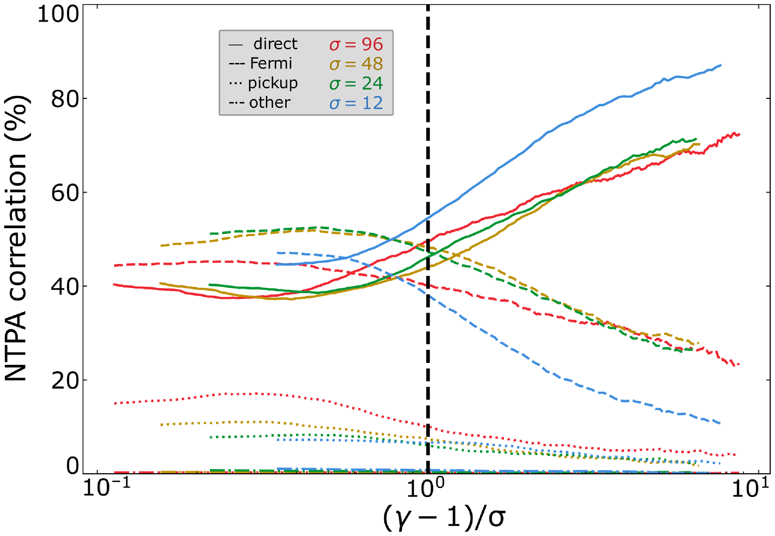
In figure 8(b), we compare two and three dimensions. Adding a third dimension appears to slightly dampen the direct acceleration correlations, with ${\sim}75\,\%$
of particles at
${\sim}75\,\%$
of particles at $\gamma = \gamma _c$
being injected by direct acceleration rather than
$\gamma = \gamma _c$
being injected by direct acceleration rather than ${\sim}90\,\%$
at
${\sim}90\,\%$
at $\sigma = 12$
.
$\sigma = 12$
.
In summary, despite direct acceleration injecting only ${\simeq} 40$
%–
${\simeq} 40$
%– $50\,\%$
of particles, there is a
$50\,\%$
of particles, there is a ${\sim}80\,\%$
NTPA correlation between the particles with
${\sim}80\,\%$
NTPA correlation between the particles with $\gamma {\sim}\gamma _c$
and injection by direct acceleration. These results may explain some of the disparities in the literature on particle injection in the weak guide field (
$\gamma {\sim}\gamma _c$
and injection by direct acceleration. These results may explain some of the disparities in the literature on particle injection in the weak guide field ( $b_g \lesssim 0.3$
) regime, wherein Totorica et al. (Reference Totorica, Zenitani, Matsukiyo, Machida, Sekiguchi and Bhattacharjee2023) and Gupta et al. (Reference Gupta, Sridhar and Sironi2025) found direct acceleration to dominate NTPA correlations and French et al. (Reference French, Guo, Zhang and Uzdensky2023) found Fermi kicks to dominate injection shares. We elaborate further in § 5.2.
$b_g \lesssim 0.3$
) regime, wherein Totorica et al. (Reference Totorica, Zenitani, Matsukiyo, Machida, Sekiguchi and Bhattacharjee2023) and Gupta et al. (Reference Gupta, Sridhar and Sironi2025) found direct acceleration to dominate NTPA correlations and French et al. (Reference French, Guo, Zhang and Uzdensky2023) found Fermi kicks to dominate injection shares. We elaborate further in § 5.2.
5. Discussion
5.1. The injection criterion
Historically, the meaning of the term injection in the published literature on relativistic magnetic reconnection has varied. The works by Ball et al. (Reference Ball, Sironi and Özel2019), Kilian et al. (Reference Kilian, Li, Guo and Zhang2020) and French et al. (Reference French, Guo, Zhang and Uzdensky2023) consider injection to be the energisation of particles up until the low-energy bound of the power-law spectrum. Meanwhile, Sironi (Reference Sironi2022), Totorica et al. (Reference Totorica, Zenitani, Matsukiyo, Machida, Sekiguchi and Bhattacharjee2023) and Gupta et al. (Reference Gupta, Sridhar and Sironi2025) describe injection as the ‘early stages’ of particle acceleration. Nevertheless, each concept has been made rigorous in a similar fashion by:
-
(i) defining ‘injection’ as the acceleration that occurs up to a threshold energy
$\gamma _{\textrm {inj}}$
(Ball et al. Reference Ball, Sironi and Özel2019; Kilian et al. Reference Kilian, Li, Guo and Zhang2020; Sironi Reference Sironi2022; French et al. Reference French, Guo, Zhang and Uzdensky2023; Totorica et al. Reference Totorica, Zenitani, Matsukiyo, Machida, Sekiguchi and Bhattacharjee2023; Gupta et al. Reference Gupta, Sridhar and Sironi2025); and -
(ii) modelling this threshold as
$\gamma _{\textrm {inj}} = 1 + \sigma$
(Ball et al. Reference Ball, Sironi and Özel2019; Kilian et al. Reference Kilian, Li, Guo and Zhang2020; Sironi Reference Sironi2022) or
$\gamma _{\textrm {inj}} = 1 + \sigma /4$
(Sironi Reference Sironi2022; Totorica et al. Reference Totorica, Zenitani, Matsukiyo, Machida, Sekiguchi and Bhattacharjee2023; Gupta et al. Reference Gupta, Sridhar and Sironi2025).



While we (in the present work and in French et al. (Reference French, Guo, Zhang and Uzdensky2023)) retained convention (i), i.e. that there exists a certain characteristic energy $\gamma _{\textrm {inj}}$
, surpassing which can serve as the criterion for injection, we discarded assumption (ii), opting instead to measure
$\gamma _{\textrm {inj}}$
, surpassing which can serve as the criterion for injection, we discarded assumption (ii), opting instead to measure $\gamma _{\textrm {inj}}$
from particle spectra directly. Our procedure for measuring
$\gamma _{\textrm {inj}}$
from particle spectra directly. Our procedure for measuring $\gamma _{\textrm {inj}}$
(cf. Appendix B and French et al. (Reference French, Guo, Zhang and Uzdensky2023)) is guided by the first conception mentioned above, i.e. injection as the energisation of particles up until the low-energy bound of the non-thermal power-law spectrum.
$\gamma _{\textrm {inj}}$
(cf. Appendix B and French et al. (Reference French, Guo, Zhang and Uzdensky2023)) is guided by the first conception mentioned above, i.e. injection as the energisation of particles up until the low-energy bound of the non-thermal power-law spectrum.
Our measurements in the present work (where $b_g = 0.3$
and
$b_g = 0.3$
and $\theta _0 = 0.3$
) have revealed that the
$\theta _0 = 0.3$
) have revealed that the $\gamma _{\textrm {inj}} = \sigma$
model vastly overestimates the low-energy bound of the power-law spectrum in both two and three dimensions (figure 5
d). In two dimensions, the
$\gamma _{\textrm {inj}} = \sigma$
model vastly overestimates the low-energy bound of the power-law spectrum in both two and three dimensions (figure 5
d). In two dimensions, the $\gamma _{\textrm {inj}} = 1 + \sigma /4$
model still overestimates measurements for
$\gamma _{\textrm {inj}} = 1 + \sigma /4$
model still overestimates measurements for $\sigma \gtrsim 30$
; however, in three dimensions we lack the data at such high values of
$\sigma \gtrsim 30$
; however, in three dimensions we lack the data at such high values of $\sigma$
to make the same conclusion.
$\sigma$
to make the same conclusion.
The 2-D measurements are, however, consistent with our model for the injection criterion, which defines a particle as injected if its gyroradius $r_g$
exceeds the elementary CS half-thickness
$r_g$
exceeds the elementary CS half-thickness $\delta /2 \simeq d_{\textrm {e, rel}}/2 = c/(2\omega _{\textrm {pe, rel}})$
(cf. § 2.1). In the thermally dominated regime, this yields an injection energy
$\delta /2 \simeq d_{\textrm {e, rel}}/2 = c/(2\omega _{\textrm {pe, rel}})$
(cf. § 2.1). In the thermally dominated regime, this yields an injection energy $\gamma _{\textrm {inj}} \simeq \sigma [ \sigma _h^{-1} \, (1 + b_g^2)/2 ]^{1/2}$
. In particular, this model is consistent with our measurements of the upstream magnetisation dependence of
$\gamma _{\textrm {inj}} \simeq \sigma [ \sigma _h^{-1} \, (1 + b_g^2)/2 ]^{1/2}$
. In particular, this model is consistent with our measurements of the upstream magnetisation dependence of $\gamma _{\textrm {inj}}$
in two dimensions (figure 5
d). In three dimensions, however, the model systematically underestimates the measurements, which we speculate is owed to CSs disrupting at greater thicknesses in three dimensions.
$\gamma _{\textrm {inj}}$
in two dimensions (figure 5
d). In three dimensions, however, the model systematically underestimates the measurements, which we speculate is owed to CSs disrupting at greater thicknesses in three dimensions.
A potentially important implication of this model is that if no particles can achieve $r_g \geqslant \delta /2$
, then no particles are injected and thus a power-law spectrum of non-thermal particles does not form. Therefore, if one can determine a priori whether any particles can be injected, one could determine precisely, from system parameters alone, the conditions under which a power-law spectrum can form. A future study could test this systematically by (a) varying
$r_g \geqslant \delta /2$
, then no particles are injected and thus a power-law spectrum of non-thermal particles does not form. Therefore, if one can determine a priori whether any particles can be injected, one could determine precisely, from system parameters alone, the conditions under which a power-law spectrum can form. A future study could test this systematically by (a) varying $\sigma _h$
from
$\sigma _h$
from $\sigma _h \lesssim 1$
to
$\sigma _h \lesssim 1$
to $\sigma _h \gg k^{-1}$
, (b) estimating the injection energy and the work done by each mechanism over this parameter range and (c) seeing whether the formation of a power-law spectrum coincides with the ability for at least one mechanism to inject particles. Moreover, a future study could examine the effects of using an electron–ion plasma, where the two-tiered structure of CSs may have a significant effect on the injection energy and relevant injection mechanisms for each species.
$\sigma _h \gg k^{-1}$
, (b) estimating the injection energy and the work done by each mechanism over this parameter range and (c) seeing whether the formation of a power-law spectrum coincides with the ability for at least one mechanism to inject particles. Moreover, a future study could examine the effects of using an electron–ion plasma, where the two-tiered structure of CSs may have a significant effect on the injection energy and relevant injection mechanisms for each species.
While the present study focuses on a single guide-field strength $b_g = 0.3$
, the injection criterion developed in § 2.1 provides insight into the expected guide-field dependence of
$b_g = 0.3$
, the injection criterion developed in § 2.1 provides insight into the expected guide-field dependence of $\gamma _{\textrm {inj}}$
. The explicit factor of
$\gamma _{\textrm {inj}}$
. The explicit factor of $( 1 + b_g^2 )^{1/2}$
in (2.4) implies that stronger guide fields increase the injection energy, as the enhanced total magnetic field strength reduces the particle gyroradius and thus requires greater particle energy to satisfy the criterion
$( 1 + b_g^2 )^{1/2}$
in (2.4) implies that stronger guide fields increase the injection energy, as the enhanced total magnetic field strength reduces the particle gyroradius and thus requires greater particle energy to satisfy the criterion $r_g \geqslant \delta /2$
. For weak guide fields (
$r_g \geqslant \delta /2$
. For weak guide fields ( $b_g \ll 1$
),
$b_g \ll 1$
), $\gamma _{\textrm {inj}}$
is insensitive to
$\gamma _{\textrm {inj}}$
is insensitive to $b_g$
, whereas for strong guide fields (
$b_g$
, whereas for strong guide fields ( $b_g \gtrsim 1$
),
$b_g \gtrsim 1$
), $\gamma _{\textrm {inj}}$
grows approximately linearly with
$\gamma _{\textrm {inj}}$
grows approximately linearly with $b_g$
. This scaling is roughly consistent with measurements in French et al. (Reference French, Guo, Zhang and Uzdensky2023), which focused on 2-D reconnection and found that
$b_g$
. This scaling is roughly consistent with measurements in French et al. (Reference French, Guo, Zhang and Uzdensky2023), which focused on 2-D reconnection and found that $\gamma _{\textrm {inj}}/\sigma$
increases from
$\gamma _{\textrm {inj}}/\sigma$
increases from ${\sim}0.15$
at
${\sim}0.15$
at $b_g = 0.1$
to
$b_g = 0.1$
to ${\sim}0.30$
at
${\sim}0.30$
at $b_g = 1.0$
. A systematic study that compares measurements of
$b_g = 1.0$
. A systematic study that compares measurements of $\gamma _{\textrm {inj}}$
over varying both
$\gamma _{\textrm {inj}}$
over varying both $b_g$
and
$b_g$
and $\sigma$
in 3-D relativistic reconnection remains a direction for future work.
$\sigma$
in 3-D relativistic reconnection remains a direction for future work.
5.2. The injection shares and NTPA correlations
In addition to the injection criterion having differing conceptions in the literature (§ 5.1), there have also been differing conceptions about how to evaluate the relative importance of various injection mechanisms. In this work and French et al. (Reference French, Guo, Zhang and Uzdensky2023), we consider injection shares – i.e. the fractional contribution of each mechanism to the total injected particle population – to reflect that mechanism’s importance. In contrast, works by Totorica et al. (Reference Totorica, Zenitani, Matsukiyo, Machida, Sekiguchi and Bhattacharjee2023) and Gupta et al. (Reference Gupta, Sridhar and Sironi2025) essentiallyFootnote 3 consider NTPA correlations, evaluated at the highest permissible energies, to reflect mechanism importance.
Despite these studies evaluating different mechanisms, we may nevertheless make a comparison with the NTPA correlations evaluated in this study. Indeed, we also find that the higher the final particle energy, the greater the likelihood (approaching ${\sim}80\,\%$
) that the particle was injected by direct acceleration, which is often associated with non-ideal (including
${\sim}80\,\%$
) that the particle was injected by direct acceleration, which is often associated with non-ideal (including $E\gt B$
) electric fields when
$E\gt B$
) electric fields when $b_g \sim 0$
(figures 8, 9). However, while NTPA correlations at high energies [e.g.
$b_g \sim 0$
(figures 8, 9). However, while NTPA correlations at high energies [e.g. $\mathcal{C}_i(\gamma = \gamma _c)$
] can certainly be quite useful in their own right, they have little bearing on the dominant injection mechanism. This is because particles with a head start in entering the power law – such as those injected by direct acceleration, which dominates at early times as suggested by figure 7 – will participate in the continual Fermi mechanism that operates in the power law for a longer duration, allowing them to achieve the highest energies. This significantly biases
$\mathcal{C}_i(\gamma = \gamma _c)$
] can certainly be quite useful in their own right, they have little bearing on the dominant injection mechanism. This is because particles with a head start in entering the power law – such as those injected by direct acceleration, which dominates at early times as suggested by figure 7 – will participate in the continual Fermi mechanism that operates in the power law for a longer duration, allowing them to achieve the highest energies. This significantly biases $\mathcal{C}_i(\gamma = \gamma _c)$
as a metric for evaluating particle injection, since the particles injected at times closer to
$\mathcal{C}_i(\gamma = \gamma _c)$
as a metric for evaluating particle injection, since the particles injected at times closer to $t_{\textrm {onset}}$
are over-represented.
$t_{\textrm {onset}}$
are over-represented.
Conversely, the injection shares can be read off figure 2(b) of Totorica et al. (Reference Totorica, Zenitani, Matsukiyo, Machida, Sekiguchi and Bhattacharjee2023) by evaluating each line at $\epsilon _{\textrm {final}} = \epsilon ^*$
, which yields
$\epsilon _{\textrm {final}} = \epsilon ^*$
, which yields $\boldsymbol{E}_n$
contributing
$\boldsymbol{E}_n$
contributing ${\sim}30\,\%$
to the injected particle population for the threshold
${\sim}30\,\%$
to the injected particle population for the threshold $\epsilon ^* = \sigma /4$
for reconnection with
$\epsilon ^* = \sigma /4$
for reconnection with $\sigma = 50, \, b_g = 0.125$
; this is somewhat consistent with our previous work which found
$\sigma = 50, \, b_g = 0.125$
; this is somewhat consistent with our previous work which found $W_\parallel$
to contribute
$W_\parallel$
to contribute ${\sim}20\,\%$
for the threshold
${\sim}20\,\%$
for the threshold $\gamma _{\textrm {inj}} \simeq 1 + \sigma /6$
when
$\gamma _{\textrm {inj}} \simeq 1 + \sigma /6$
when $\sigma = 50, \, b_g = 0.1$
(French et al. Reference French, Guo, Zhang and Uzdensky2023). Likewise, the injection shares can be read off figure 3 of Gupta et al. (Reference Gupta, Sridhar and Sironi2025) by evaluating each line at
$\sigma = 50, \, b_g = 0.1$
(French et al. Reference French, Guo, Zhang and Uzdensky2023). Likewise, the injection shares can be read off figure 3 of Gupta et al. (Reference Gupta, Sridhar and Sironi2025) by evaluating each line at $\epsilon _T/\sigma = \epsilon ^*$
, which shows that
$\epsilon _T/\sigma = \epsilon ^*$
, which shows that $E\gt B$
electric fields inject
$E\gt B$
electric fields inject ${\sim}5\,\%$
of particles, in rough agreement with Guo et al. (Reference Guo, Li, French, Zhang, Daughton, Liu, Matthaeus, Kilian, Johnson and Li2023).
${\sim}5\,\%$
of particles, in rough agreement with Guo et al. (Reference Guo, Li, French, Zhang, Daughton, Liu, Matthaeus, Kilian, Johnson and Li2023).
The guide-field strength is also expected to affect the relative contributions of the injection mechanisms. As shown in (2.13) and (2.14), both Fermi kicks and pickup acceleration are suppressed by factors containing $(1 + \sigma b_g^2)$
in the denominator. Consequently, for weak guide fields (
$(1 + \sigma b_g^2)$
in the denominator. Consequently, for weak guide fields ( $b_g \ll \sigma ^{-1/2}$
), these mechanisms associated with the motional (perpendicular) electric field can efficiently inject particles, whereas for strong guide fields (
$b_g \ll \sigma ^{-1/2}$
), these mechanisms associated with the motional (perpendicular) electric field can efficiently inject particles, whereas for strong guide fields ( $b_g \gtrsim 1$
), their energisation is significantly damped. In the strong guide-field regime, direct acceleration by the parallel electric field – which is not suppressed by the guide field – is expected to dominate the injection process. This trend is consistent with French et al. (Reference French, Guo, Zhang and Uzdensky2023), which found that
$b_g \gtrsim 1$
), their energisation is significantly damped. In the strong guide-field regime, direct acceleration by the parallel electric field – which is not suppressed by the guide field – is expected to dominate the injection process. This trend is consistent with French et al. (Reference French, Guo, Zhang and Uzdensky2023), which found that $W_\parallel$
contributions increase from
$W_\parallel$
contributions increase from ${\sim}20\,\%$
to
${\sim}20\,\%$
to ${\sim}70\,\%$
as
${\sim}70\,\%$
as $b_g$
increases from
$b_g$
increases from $0.1$
to
$0.1$
to $1.0$
.
$1.0$
.
5.3. The high-energy cutoff
$\gamma _c$

Power-law spectra are often modelled with an exponential cutoff, i.e. $f(\gamma ) \sim \gamma ^{-p}\, e^{-\gamma /\gamma _c}$
, where
$f(\gamma ) \sim \gamma ^{-p}\, e^{-\gamma /\gamma _c}$
, where $\gamma _c$
is the high-energy cutoff. We will discuss here two questions about this quantity: (a) How does
$\gamma _c$
is the high-energy cutoff. We will discuss here two questions about this quantity: (a) How does $\gamma _c$
evolve with time? (b) How does
$\gamma _c$
evolve with time? (b) How does $\gamma _c$
vary with upstream magnetisation
$\gamma _c$
vary with upstream magnetisation $\sigma \,?$
Let us begin with the first question. The time evolution of $\gamma _c$
can be roughly decomposed into three phases: (i) the short, transient phase of rapid rise which immediately follows reconnection onset (
$\gamma _c$
can be roughly decomposed into three phases: (i) the short, transient phase of rapid rise which immediately follows reconnection onset ( $t_{\textrm {onset}} \lt t \lt t_1$
), (ii) an intermediate phase, characterised by a mixed reconnection layer that is populated with both CSs and developing plasmoids (
$t_{\textrm {onset}} \lt t \lt t_1$
), (ii) an intermediate phase, characterised by a mixed reconnection layer that is populated with both CSs and developing plasmoids ( $t_1 \lt t \lt t_{\textrm {ss}}$
), and (iii) the slow, quasi-steady phase, characterised by a fully developed multi-plasmoid dynamics in the reconnection layer (
$t_1 \lt t \lt t_{\textrm {ss}}$
), and (iii) the slow, quasi-steady phase, characterised by a fully developed multi-plasmoid dynamics in the reconnection layer ( $t \gt t_{\textrm {ss}}$
). We show how
$t \gt t_{\textrm {ss}}$
). We show how $\gamma _c$
evolves during these phases in three dimensions for several values of
$\gamma _c$
evolves during these phases in three dimensions for several values of $\sigma$
in figure 5(e) (§ 4.2).
$\sigma$
in figure 5(e) (§ 4.2).
To our knowledge, no dedicated study has yet numerically explored the evolution $\gamma _c(t)$
systematically during phase (i). Our high-cadence depositions of particle spectra have enabled us to explore this for the first time in detail. We find that this phase lasts approximately
$\gamma _c(t)$
systematically during phase (i). Our high-cadence depositions of particle spectra have enabled us to explore this for the first time in detail. We find that this phase lasts approximately $(3/8) \, L_x/c \simeq 100 \, \sigma \omega _{\textrm {ce}}^{-1}$
; our measurements of
$(3/8) \, L_x/c \simeq 100 \, \sigma \omega _{\textrm {ce}}^{-1}$
; our measurements of $\gamma _c(t)$
adhere closely to the simple linear form
$\gamma _c(t)$
adhere closely to the simple linear form $\gamma _c(t) = a\, \omega _{\textrm {ce}}(t - t_{\textrm {onset}})$
in both two and three dimensions, where
$\gamma _c(t) = a\, \omega _{\textrm {ce}}(t - t_{\textrm {onset}})$
in both two and three dimensions, where $a = 0.017 \pm 0.003$
is a fitting parameter. This scaling of
$a = 0.017 \pm 0.003$
is a fitting parameter. This scaling of $\gamma _c(t)$
agrees with the time-dependent work done by the reconnection electric field,
$\gamma _c(t)$
agrees with the time-dependent work done by the reconnection electric field, $W_{\textrm {direct}}(t) = \eta _{\textrm {rec}} \omega _{\textrm {ce}} t \, m_e c^2$
, except somewhat smaller in magnitude (
$W_{\textrm {direct}}(t) = \eta _{\textrm {rec}} \omega _{\textrm {ce}} t \, m_e c^2$
, except somewhat smaller in magnitude ( $\gamma _c(t) \simeq W_{\textrm {direct}}/6 m_e c^2$
). This agreement conveys a narrative consistent with the injection shares, which suggest that direct acceleration in small, elementary diffusion regions around X-points is the exclusive injector of particles during the first
$\gamma _c(t) \simeq W_{\textrm {direct}}/6 m_e c^2$
). This agreement conveys a narrative consistent with the injection shares, which suggest that direct acceleration in small, elementary diffusion regions around X-points is the exclusive injector of particles during the first $0.25 \, L_x/c$
following reconnection onset (figure 7). The discrepancy of
$0.25 \, L_x/c$
following reconnection onset (figure 7). The discrepancy of ${\sim} 1/6$
may be attributed to the fact that particles with finite drift in the
${\sim} 1/6$
may be attributed to the fact that particles with finite drift in the $x$
–
$x$
– $y$
plane will leave elementary diffusion regions around X-points on microscopic time scales.
$y$
plane will leave elementary diffusion regions around X-points on microscopic time scales.
The existence of an intermediate phase in three dimensions where $\gamma _c(t) \sim t^{r}$
for
$\gamma _c(t) \sim t^{r}$
for $0.5 \lt r \lt 1.0$
may be attributed to particles that have escaped plasmoids (e.g. disrupted by the flux-rope kink instability) and enter Speiser-like orbits which energise them as
$0.5 \lt r \lt 1.0$
may be attributed to particles that have escaped plasmoids (e.g. disrupted by the flux-rope kink instability) and enter Speiser-like orbits which energise them as $\gamma \sim t$
(Uzdensky et al. Reference Uzdensky, Cerutti and Begelman2011; Cerutti et al. Reference Cerutti, Uzdensky and Begelman2012, Reference Cerutti, Werner, Uzdensky and Begelman2014; Dahlin, Drake & Swisdak Reference Dahlin, Drake and Swisdak2017; Zhang et al. Reference Zhang, Guo, Daughton, Li and Li2021). As plasmoids develop in the reconnection layer, the relative population of ‘trapped’ (
$\gamma \sim t$
(Uzdensky et al. Reference Uzdensky, Cerutti and Begelman2011; Cerutti et al. Reference Cerutti, Uzdensky and Begelman2012, Reference Cerutti, Werner, Uzdensky and Begelman2014; Dahlin, Drake & Swisdak Reference Dahlin, Drake and Swisdak2017; Zhang et al. Reference Zhang, Guo, Daughton, Li and Li2021). As plasmoids develop in the reconnection layer, the relative population of ‘trapped’ ( $\gamma \sim \sqrt {t}$
) to ‘free’ (
$\gamma \sim \sqrt {t}$
) to ‘free’ ( $\gamma \sim t$
) particles increases, eventually leading to the steady-state phase wherein
$\gamma \sim t$
) particles increases, eventually leading to the steady-state phase wherein $\gamma _c \sim \sqrt {t}$
.
$\gamma _c \sim \sqrt {t}$
.
During the subsequent quasi-steady phase (i.e. $t \gt t_{\textrm {ss}}$
), previous 2-D studies by Petropoulou & Sironi (Reference Petropoulou and Sironi2018) and Hakobyan et al. (Reference Hakobyan, Petropoulou, Spitkovsky and Sironi2021) discovered that the high-energy cutoff grows as
$t \gt t_{\textrm {ss}}$
), previous 2-D studies by Petropoulou & Sironi (Reference Petropoulou and Sironi2018) and Hakobyan et al. (Reference Hakobyan, Petropoulou, Spitkovsky and Sironi2021) discovered that the high-energy cutoff grows as $\gamma _c \sim \sqrt {t}$
due to the adiabatic compression of plasmoids. This scaling of
$\gamma _c \sim \sqrt {t}$
due to the adiabatic compression of plasmoids. This scaling of $\gamma _c \sim \sqrt {t}$
has also been found in three dimensions in the transrelativistic
$\gamma _c \sim \sqrt {t}$
has also been found in three dimensions in the transrelativistic $\sigma _h = 1$
regime by Werner & Uzdensky (Reference Werner and Uzdensky2021). Our results reaffirm this scaling in both two and three dimensions, where the measured
$\sigma _h = 1$
regime by Werner & Uzdensky (Reference Werner and Uzdensky2021). Our results reaffirm this scaling in both two and three dimensions, where the measured $\gamma _c(t \gt t_{\textrm {ss}})$
adheres closely to the model
$\gamma _c(t \gt t_{\textrm {ss}})$
adheres closely to the model $\gamma _c(t \gt t_{\textrm {ss}}) \simeq 4 \sigma [ c(t - t_{\textrm {onset}})/L_x ]^{1/2}$
in two dimensions (not shown) and
$\gamma _c(t \gt t_{\textrm {ss}}) \simeq 4 \sigma [ c(t - t_{\textrm {onset}})/L_x ]^{1/2}$
in two dimensions (not shown) and $\gamma _c(t \gt t_{\textrm {ss}}) \simeq 6 \sigma [ c(t - t_{\textrm {onset}})/L_x ]^{1/2}$
in three dimensions (figure 5
e). Our work in three dimensions does not, however, access the high-
$\gamma _c(t \gt t_{\textrm {ss}}) \simeq 6 \sigma [ c(t - t_{\textrm {onset}})/L_x ]^{1/2}$
in three dimensions (figure 5
e). Our work in three dimensions does not, however, access the high- $\sigma$
, large-
$\sigma$
, large- $L_x$
regime wherein secondary power laws of
$L_x$
regime wherein secondary power laws of $\gamma ^{-2}$
at higher energies have been found (Zhang et al. Reference Zhang, Sironi, Giannios and Petropoulou2023).
$\gamma ^{-2}$
at higher energies have been found (Zhang et al. Reference Zhang, Sironi, Giannios and Petropoulou2023).
The second question of how $\gamma _c$
varies with
$\gamma _c$
varies with $\sigma$
was originally explored by Werner et al. (Reference Werner, Uzdensky, Cerutti, Nalewajko and Begelman2016), who found
$\sigma$
was originally explored by Werner et al. (Reference Werner, Uzdensky, Cerutti, Nalewajko and Begelman2016), who found $\gamma _c \simeq 4\sigma$
in two dimensions. We also find
$\gamma _c \simeq 4\sigma$
in two dimensions. We also find $\gamma _c \sim \sigma$
in both two and three dimensions but with a time-dependent coefficient in accordance with Petropoulou & Sironi (Reference Petropoulou and Sironi2018) (figure 5
f).
$\gamma _c \sim \sigma$
in both two and three dimensions but with a time-dependent coefficient in accordance with Petropoulou & Sironi (Reference Petropoulou and Sironi2018) (figure 5
f).
Combining our understanding of these two questions allows us to construct a more complete description of the high-energy cutoff evolution in 3-D relativistic magnetic reconnection (4.2).
6. Conclusions
The primary goal of this work was to understand energetic particle injection in relativistic magnetic reconnection – a poorly understood yet essential aspect of reconnection-driven non-thermal particle acceleration. Therefore, we sought to elucidate (i) what is and what sets the injection criterion and (ii) what physical mechanisms promote the particles to satisfy the criterion.
More concretely, we performed an array of PIC simulations of a reconnecting relativistic collisionless pair plasma immersed in a weak guide field of $b_g = 0.3$
. From these simulations, we (i) measured the injection energy
$b_g = 0.3$
. From these simulations, we (i) measured the injection energy $\gamma _{\textrm {inj}}$
(§ 4.2) and (ii) evaluated the time-dependent contributions of three distinct acceleration mechanisms to the total injected particle population (§ 4.4), and investigated how these quantities depend on the upstream magnetisation
$\gamma _{\textrm {inj}}$
(§ 4.2) and (ii) evaluated the time-dependent contributions of three distinct acceleration mechanisms to the total injected particle population (§ 4.4), and investigated how these quantities depend on the upstream magnetisation $\sigma \in \{ 8, 12, 16, 24, 32, 48, 64, 96\}$
and dimensionality (two vs three dimensions). We have also devised a physical model for
$\sigma \in \{ 8, 12, 16, 24, 32, 48, 64, 96\}$
and dimensionality (two vs three dimensions). We have also devised a physical model for $\gamma _{\textrm {inj}}$
(§ 2.1) which is consistent with 2-D results.
$\gamma _{\textrm {inj}}$
(§ 2.1) which is consistent with 2-D results.
This work also had the secondary goals of (i) evaluating the injection and energy efficiencies $\eta _N$
and
$\eta _N$
and $\eta _E$
(§ 4.3) and (ii) uncovering the NTPA correlations of each mechanism, i.e. the correlations between injected particle energy and injection mechanism of origin (§ 4.5). We summarise our findings in the rest of this section.
$\eta _E$
(§ 4.3) and (ii) uncovering the NTPA correlations of each mechanism, i.e. the correlations between injected particle energy and injection mechanism of origin (§ 4.5). We summarise our findings in the rest of this section.
6.1. Characteristic spectral parameters and efficiencies
Using a novel procedure for fitting power-law spectra, we have been able to acquire the three key spectral parameters – power-law index $p$
, injection energy
$p$
, injection energy $\gamma _{\textrm {inj}}$
, and cutoff energy
$\gamma _{\textrm {inj}}$
, and cutoff energy $\gamma _c$
(from
$\gamma _c$
(from $f \sim \gamma ^{-p} e^{-\gamma /\gamma _c}, \gamma \in [\gamma _{\textrm {inj}}, \infty )$
) – with unprecedented precision (see Appendix B for details). This has enabled us to assert the following conclusions:
$f \sim \gamma ^{-p} e^{-\gamma /\gamma _c}, \gamma \in [\gamma _{\textrm {inj}}, \infty )$
) – with unprecedented precision (see Appendix B for details). This has enabled us to assert the following conclusions:
-
(i) Injection energy
$\boldsymbol{\gamma }_{\textrm {inj}}$
: the injection energy
$\gamma _{\textrm {inj}}$
(i.e. the energy at which the power-law component of the downstream particle spectrum begins) grows sub-linearly with increasing magnetisation
$\sigma$
. In particular,
$\gamma _{\textrm {inj}} \simeq 5$
to
$12$
when varying
$\sigma = 8$
to
$96$
in two dimensions and
$\gamma _{\textrm {inj}} \simeq 7$
to
$12$
when varying
$\sigma = 8$
to
$32$
in three dimensions;
${\sim} 50\,\%$
greater than 2-D measurements for each value of
$\sigma$
.The 2-D measurements of
$\gamma _{\textrm {inj}}$
adhere well to the model we developed for the injection criterion, specifically in the thermally dominated regime (i.e. the intermediate
$\sigma _h$
regime whereupon the plasma temperature inside elementary CSs is governed by the ambient upstream plasma), wherein the injection energy is
$\gamma _{\textrm {inj}} \simeq \sigma [ \sigma _h^{-1} (1 + b_g^2)/2 ]^{1/2}$
(§ 2.1, figure 5
d). In contrast, in three dimensions the model consistently underestimates the measurements by a factor of
${\sim} 1.5$
. -
(ii) Power-law index
$p$
: after reconnection onset, power-law spectra rapidly harden to
$p \lesssim 2$
and then gradually soften, stabilising at
$t \sim t_{\textrm {onset}}+ 400 \, \sigma \omega _{\textrm {ce}}^{-1}$
(figure 5
a). At final times (i.e.
$t = t_{\textrm {onset}} + 3\,L_x/c$
), the power-law index
$p$
declines with increasing
$\sigma$
, varying from
$p \simeq 2.5$
to
$1.9$
when varying
$\sigma = 8$
to
$96$
in two dimensions and
$p \simeq 2.8$
to
$2.2$
when varying
$\sigma = 8$
to
$32$
in three dimensions. Power-law spectra are consistently steeper by
$0.2$
–
$0.3$
in three dimensions compared with two dimensions for the same value of
$\sigma$
(figure 5
b). -
(iii) Cutoff energy
$\boldsymbol{\gamma }_c$
: during the first
${\sim} 65 \, \sigma \omega _{\textrm {ce}}^{-1}$
following reconnection onset, virtually the only injection mechanism that is active is direct acceleration by
$E_{\textrm {rec}}$
in non-ideal reconnection diffusion regions (cf. figure 7
a). Hence we sought to test whether during its initial rise
$\gamma _c(t)$
would evolve similarly to
$W_{\textrm {direct}}$
, i.e.
$\dot {\gamma }_c \sim \dot {W}_{\textrm {direct}} = \eta _{\textrm {rec}} \omega _{\textrm {ce}} \simeq 0.1 \, \omega _{\textrm {ce}}$
. Indeed, we found that
$\gamma _c(t) = a\, \omega _{\textrm {ce}} (t - t_{\textrm {onset}}) \simeq W_{\textrm {direct}}(t - t_{\textrm {onset}})/6$
closely matches the
$\gamma _c$
measurements during the early transient period
$t - t_{\textrm {onset}} \lt (3/8) \, L_x/c \simeq 100 \, \sigma \omega _{\textrm {ce}}^{-1}$
(figure 5
e). After this transient period, we find that
$\gamma _c(t)$
transitions to a slower-growth second stage, adhering closely to
$\gamma _c(t) \simeq 4\sigma [ c(t - t_{\textrm {onset}})/L_x ]^{1/2}$
in two dimensions and
$\gamma _c(t) \simeq 6\sigma [ c(t - t_{\textrm {onset}})/L_x ]^{1/2}$
in three dimensions, in agreement with previous work (cf. § 5.3), see figure 5(e). -
(iv) Injection efficiency
$\mathbf{\eta _N}$
and energy efficiency
$\mathbf{\eta _E}$
: the ‘efficiencies’ of injection
$\eta _N \equiv N_{\textrm {inj}}/N_{\textrm {ds}}$
((4.4); i.e. the fraction of the downstream particles that are injected) and energy
$\eta _E \equiv E_{\textrm {inj}}/E_{\textrm {ds}}$
[(4.5); i.e. the fraction of the downstream particle kinetic energy carried by injected particles] grows rapidly during the first
${\sim} 0.5 \, L_x/c$
that follows reconnection onset (figure 6
a, c). Subsequently, these efficiencies continue to grow throughout the simulation, but slower, and after
$t - t_{\textrm {onset}} \gtrsim 2 \, L_x/c$
saturate at finite,
$\sigma$
-dependent values
$\eta _{N,\textrm {sat}}(\sigma )$
and
$\eta _{E,\textrm {sat}}(\sigma )$
.The late-time saturated injection efficiency
$\eta _{N, \textrm {sat}}(\sigma )$
increases with
$\sigma$
in both two and three dimensions. In particular, in two dimensions it grows from approximately 30 % to 40 % as
$\sigma = 8$
to
$96$
, while in three dimensions it increases from approximately 15 % to 25 % as
$\sigma = 8$
to
$32$
(figure 6
b, d). Likewise, the time-saturated energy efficiency
$\eta _{E,\textrm {sat}}(\sigma )$
also grows with
$\sigma$
, increasing from 60 % to 90 % as
$\sigma = 8$
to
$96$
in two dimensions and from 50 % to 70 % as
$\sigma = 8$
to
$32$
in three dimensions.In two dimensions, the
$\sigma$
-convergence of the efficiencies around
$\eta _{N,\textrm {sat}}(\sigma ) \simeq 40\,\%$
and
$\eta _{E,\textrm {sat}}(\sigma ) \simeq 90\,\%$
is realised for
$\sigma \gtrsim 50$
, whereas in three dimensions such convergence is not yet established, likely due to the limited
$\sigma$
-range covered by our 3-D simulations. These
$\sigma$
-converged 2-D measurements are in agreement with our previous study (French et al. Reference French, Guo, Zhang and Uzdensky2023). The consistently lower values of
$\eta _{N, \textrm {sat}}(\sigma )$
,
$\eta _{E, \textrm {sat}}(\sigma )$
in three dimensions are likely owed to the steeper power-law spectra found in three dimensions (figure 5
b).




























6.2. Injection mechanism shares and NTPA correlations
-
(i) Injection shares: we find a specific activation sequence of the injection mechanisms that agrees with our geometrical picture of injection (figure 1). Denoting the time of the first tracer particle injection as
$t = \tau _{\textrm {inj}} \gtrsim t_{\textrm {onset}}$
, the first mechanism to activate is
$W_{\textrm {direct}}$
at
$t = \tau _{\textrm {inj}}$
, followed by
$W_{\textrm {Fermi}}$
at
$t \simeq \tau _{\textrm {inj}} + 0.25 \, L_x/c$
, followed by
$W_{\textrm {pickup}}$
at
$t \simeq \tau _{\textrm {inj}} + 0.5 \, L_x/c$
(figure 7
a). Importantly, of all the particles that are injected by the end of each simulation, only
${\sim} 10\,\%$
are injected during the initial
$W_{\textrm {direct}}$
-dominated phase (i.e.
$t \in [\tau _{\textrm {inj}}, \tau _{\textrm {inj}} + L_x/c]$
). This implies that while
$W_{\textrm {direct}}$
is initially important, it can nevertheless become sub-dominant when evaluating the aggregate injected particle population over a longer period.The asymptotic, late-time injection shares from Fermi kicks and direct acceleration trend toward
${\sim} 40\,\%$
and
${\sim} 50\,\%$
respectively in three dimensions (two dimensions) with increasing
$\sigma$
(figure 7
b). Pickup shares are suppressed from
$20\,\%$
(
$10\,\%$
) to
$5\,\%$
in three dimensions (two dimensions) when varying
$\sigma = 8$
to
$32$
, but rise again in two dimensions when varying
$\sigma = 48$
to
$96$
. -
(ii) NTPA correlations: to discover the probability that a given particle of high energy
$\gamma \geqslant \gamma _{\textrm {inj}}$
was injected by a certain mechanism, we compute ‘NTPA correlations’ (figure 8). We find that particles injected by
$W_{\textrm {direct}}$
comprise a majority of particles with
$\gamma \gt \sigma$
and comprise
${\sim} 80$
–
$90\,\%$
of particles with
$\gamma = \gamma _c$
. Introducing a third dimension alters this result, with the correlation between direct acceleration and particles at
$\gamma = \gamma _c$
falling from
${\sim} 90\,\%$
to
${\sim} 75\,\%$
at
$\sigma = 12$
.











This work advances our understanding of particle injection in the relativistic regime of magnetic reconnection in several ways. By systematically comparing 2-D and 3-D simulations across a broad range of upstream magnetisations, we found that 3-D effects increase injection energies by ${\sim} 50\,\%$
and that the injection energy
${\sim} 50\,\%$
and that the injection energy $\gamma _{\textrm {inj}}$
scales sub-linearly with upstream magnetisation
$\gamma _{\textrm {inj}}$
scales sub-linearly with upstream magnetisation $\sigma$
when the hot upstream magnetisation
$\sigma$
when the hot upstream magnetisation $\sigma _h$
is moderate. The theoretical picture of particle injection presented in this work provides a physical basis for understanding how particles enter continual acceleration within the power-law spectrum produced by magnetic reconnection and is consistent with measurements of injection energies in two dimensions. Moreover, by distinguishing between injection shares (quantifying the contribution of each mechanism to the injected particle population) and NTPA correlations (which mechanisms injected the particles that reach the highest energies), this work reconciles apparent contradictions in the literature on particle injection in relativistic magnetic reconnection. Finally, the time-resolved analysis of injection mechanism activation sequences and the precise spectral fitting procedure developed here establish a framework for future studies of particle injection across different plasma conditions. These results have direct implications for modelling high-energy emissions from astrophysical reconnection sites, where the existence of a thermally dominated regime implies that power-law spectra produced by magnetic reconnection in the high
$\sigma _h$
is moderate. The theoretical picture of particle injection presented in this work provides a physical basis for understanding how particles enter continual acceleration within the power-law spectrum produced by magnetic reconnection and is consistent with measurements of injection energies in two dimensions. Moreover, by distinguishing between injection shares (quantifying the contribution of each mechanism to the injected particle population) and NTPA correlations (which mechanisms injected the particles that reach the highest energies), this work reconciles apparent contradictions in the literature on particle injection in relativistic magnetic reconnection. Finally, the time-resolved analysis of injection mechanism activation sequences and the precise spectral fitting procedure developed here establish a framework for future studies of particle injection across different plasma conditions. These results have direct implications for modelling high-energy emissions from astrophysical reconnection sites, where the existence of a thermally dominated regime implies that power-law spectra produced by magnetic reconnection in the high $\sigma _h$
limit can potentially be much broader than previously expected.
$\sigma _h$
limit can potentially be much broader than previously expected.
Acknowledgements
Editor Nuno Loureiro thanks the referees for their advice in evaluating this article.
Funding
O.F. acknowledges support from the National Science Foundation Graduate Research Fellowship under Grant No. DGE 2040434. This work was also supported by the National Science Foundation via grant AST 1903335 and by NASA via grants 80NSSC20K0545, 80NSSC22K0828 and 80NSSC24K0941. This research used resources of the Anvil supercomputer, which is supported by National Science Foundation award No. 2005632 and is a resource of the Rosen Center for Advanced Computing at Purdue University. We would like to thank F. Guo for helpful discussions.
Declaration of interests
The authors report no conflict of interest.
Appendix A. Convergence studies
In general when conducting PIC simulations, it is crucial to have robust results, and as such one aims to use a domain size as large as possible. However, since one is constrained by the computational resources that exist, it is important to consider the quantities which control the computational time. For a given simulation code, the computational cost $C$
scales with the number of particle pushes, given by
$C$
scales with the number of particle pushes, given by $C \sim N_x N_y N_z N_t n_{\textrm {ppc}}$
, where
$C \sim N_x N_y N_z N_t n_{\textrm {ppc}}$
, where $N_x N_y N_z$
is the number of cells in the domain,
$N_x N_y N_z$
is the number of cells in the domain, $N_t$
is the number of pushes, and
$N_t$
is the number of pushes, and $n_{\textrm {ppc}}$
is the number of particles per cell.
$n_{\textrm {ppc}}$
is the number of particles per cell.
Since we are preserving aspect ratios to $L_x = L_y = 2L_z$
(
$L_x = L_y = 2L_z$
( $L_x = L_y$
) in three dimensions (two dimensions), the cost reduces to
$L_x = L_y$
) in three dimensions (two dimensions), the cost reduces to $C_{\textrm {2D}} \sim N_x^3 n_{\textrm {ppc}}$
in two dimensions and
$C_{\textrm {2D}} \sim N_x^3 n_{\textrm {ppc}}$
in two dimensions and $C_{\textrm {3D}} \sim N_x^4 n_{\textrm {ppc}}$
in three dimensions. In particular, for a given domain size
$C_{\textrm {3D}} \sim N_x^4 n_{\textrm {ppc}}$
in three dimensions. In particular, for a given domain size $L_x$
we may cast
$L_x$
we may cast $N_x$
in terms of spatial resolution
$N_x$
in terms of spatial resolution $L_x/N_x = \delta /\Delta x$
, where
$L_x/N_x = \delta /\Delta x$
, where $\delta$
is a local length scale and
$\delta$
is a local length scale and $\Delta x$
is the grid length. These scalings motivate using values of
$\Delta x$
is the grid length. These scalings motivate using values of $\delta /\Delta x$
and
$\delta /\Delta x$
and $n_{\textrm {ppc}}$
that are as low as possible while producing results (e.g. particle spectra, injection shares, injection efficiencies, etc.) which are (a) approximately invariant to increases of these inputs and (b) sensitive to reductions of these inputs. The parameters we have decided to use for these convergence studies are summarised in table 1.
$n_{\textrm {ppc}}$
that are as low as possible while producing results (e.g. particle spectra, injection shares, injection efficiencies, etc.) which are (a) approximately invariant to increases of these inputs and (b) sensitive to reductions of these inputs. The parameters we have decided to use for these convergence studies are summarised in table 1.
Quantities for convergence studies.
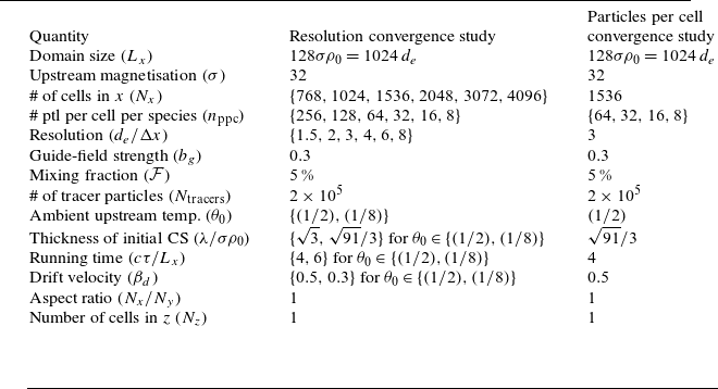
To save computational resources, we will conduct these convergence studies in two dimensions and extend the outcomes to three dimensions as follows. For resolution convergence, we will assume that the minimum spatial resolution necessary to resolve in three dimensions is identical to two dimensions. For $n_{\textrm {ppc}}$
convergence, we will assume that the number of particles per Debye
$n_{\textrm {ppc}}$
convergence, we will assume that the number of particles per Debye $n$
-sphere remain fixed, so that
$n$
-sphere remain fixed, so that $( 2 \, n^{(3D)}_{\textrm {ppc}})^3 = ( 2 \, n^{(2D)}_{\textrm {ppc}} )^2$
, allowing us to straightforwardly solve for
$( 2 \, n^{(3D)}_{\textrm {ppc}})^3 = ( 2 \, n^{(2D)}_{\textrm {ppc}} )^2$
, allowing us to straightforwardly solve for $n^{(3D)}_{\textrm {ppc}}$
.
$n^{(3D)}_{\textrm {ppc}}$
.
A.1 Resolution convergence study
The particular length scale $\delta$
which must be resolved for converged results is not obvious, and therefore we shall experiment with different scales. In order to satisfy the CFL (Courant, Friedrichs & Lewy Reference Courant, Friedrichs and Lewy1928) condition, it is necessary to forbid particles moving at light speed from traversing more than one grid length
$\delta$
which must be resolved for converged results is not obvious, and therefore we shall experiment with different scales. In order to satisfy the CFL (Courant, Friedrichs & Lewy Reference Courant, Friedrichs and Lewy1928) condition, it is necessary to forbid particles moving at light speed from traversing more than one grid length $\Delta x$
per time step
$\Delta x$
per time step $\Delta t$
, i.e.
$\Delta t$
, i.e. $d_e/\Delta x \gt 1$
, where
$d_e/\Delta x \gt 1$
, where $d_e \equiv c/\omega _{\textrm {pe}}$
is the collisionless relativistic electron skin depth. Therefore the first length scale we will test is
$d_e \equiv c/\omega _{\textrm {pe}}$
is the collisionless relativistic electron skin depth. Therefore the first length scale we will test is $d_e$
, i.e. we seek to determine whether there exists some critical resolution
$d_e$
, i.e. we seek to determine whether there exists some critical resolution $\delta _e^{\textrm {crit}}/\Delta x$
above which results vary negligibly and below which results are sensitive.
$\delta _e^{\textrm {crit}}/\Delta x$
above which results vary negligibly and below which results are sensitive.
Additionally, we will conduct a parallel set of simulations that use a different initial upstream background temperature $\theta _0 \equiv k_B T_0/m_ec^2$
. This is done to uncover which value of
$\theta _0 \equiv k_B T_0/m_ec^2$
. This is done to uncover which value of $\lambda _{\textrm {De}} \equiv \sqrt {\theta _0} \, d_e$
which must be resolved. This is also done to determine whether there exists a regime of
$\lambda _{\textrm {De}} \equiv \sqrt {\theta _0} \, d_e$
which must be resolved. This is also done to determine whether there exists a regime of $\theta _0 \lt 1$
for which all particle injection results are approximately invariant. This is of interest not only to reveal increased generality of results, but also potentially to save computational resources, because (a) using
$\theta _0 \lt 1$
for which all particle injection results are approximately invariant. This is of interest not only to reveal increased generality of results, but also potentially to save computational resources, because (a) using $\theta _0 = 1/2$
yields larger values
$\theta _0 = 1/2$
yields larger values $\lambda _{\textrm {De}}/\Delta x$
, (b) it means that a larger drift speed
$\lambda _{\textrm {De}}/\Delta x$
, (b) it means that a larger drift speed $\beta _d$
can be implemented in the initial current layer without initiating the two-stream instability, thereby causing reconnection to start earlier, and (c) the initial CS is thinner, causing it to occupy a smaller fraction of the total particle population for a given length in the
$\beta _d$
can be implemented in the initial current layer without initiating the two-stream instability, thereby causing reconnection to start earlier, and (c) the initial CS is thinner, causing it to occupy a smaller fraction of the total particle population for a given length in the $y$
-direction
$y$
-direction $L_y$
, thereby yielding more precise results for tracer particle analysis.
$L_y$
, thereby yielding more precise results for tracer particle analysis.
In this (2-D) convergence study we preserve the number of particles per Debye volume, so that doubling the resolution folds $n_{\textrm {ppc}}$
by a factor of 4.
$n_{\textrm {ppc}}$
by a factor of 4.
Regardless of whether the background temperature is $\theta _0 = 1/8$
or
$\theta _0 = 1/8$
or $1/2$
, we find that the particle spectra are invariant of resolution, implying that all resultant spectral quantities (
$1/2$
, we find that the particle spectra are invariant of resolution, implying that all resultant spectral quantities ( $\gamma _{\textrm {inj}}, \gamma _c, p, \eta _N, \eta _E$
) are converged (figure 10). Furthermore, while the injection energy (i.e. the low-energy bound of the power-law spectrum) may be difficult to visually distinguish from the thermal component when
$\gamma _{\textrm {inj}}, \gamma _c, p, \eta _N, \eta _E$
) are converged (figure 10). Furthermore, while the injection energy (i.e. the low-energy bound of the power-law spectrum) may be difficult to visually distinguish from the thermal component when $\theta _0 = 1/2$
(panel a), it becomes clear when
$\theta _0 = 1/2$
(panel a), it becomes clear when $\theta _0 = 1/8$
that
$\theta _0 = 1/8$
that $\gamma _{\textrm {inj}} \simeq 5$
.
$\gamma _{\textrm {inj}} \simeq 5$
.
Particle spectra for different resolutions. (a) Uses an ambient upstream temperature of $\theta _0 = 1/2$
whereas (b) uses
$\theta _0 = 1/2$
whereas (b) uses $\theta _0 = 1/8$
.
$\theta _0 = 1/8$
.

We show the influence of spatial resolution on the particle injection shares in figure 11. In order to display only statistically significant results, we only show injection shares after $0.1\,\%$
of the total injected tracer particle population has undergone injection. We find that the injection shares have more difficulty converging, with no clear monotonic trend emerging upon varying
$0.1\,\%$
of the total injected tracer particle population has undergone injection. We find that the injection shares have more difficulty converging, with no clear monotonic trend emerging upon varying $d_e/\Delta x = 1.5 \to 8.0$
. However, we find that
$d_e/\Delta x = 1.5 \to 8.0$
. However, we find that $\lambda _{\textrm {De}}/\Delta x \lt 1$
causes a significant break in the results (panel b).
$\lambda _{\textrm {De}}/\Delta x \lt 1$
causes a significant break in the results (panel b).
Injection shares for different resolutions. In each panel, the corresponding resolution in skin depths is $d_e/\Delta x \in \{ 8, 6, 4, 2, 1.5\}$
from dark red to blue lines. (a) Uses an ambient upstream temperature of
$d_e/\Delta x \in \{ 8, 6, 4, 2, 1.5\}$
from dark red to blue lines. (a) Uses an ambient upstream temperature of $\theta _0 = 1/2$
whereas (b) uses
$\theta _0 = 1/2$
whereas (b) uses $\theta _0 = 1/8$
.
$\theta _0 = 1/8$
.

A.2 Particles per cell convergence study
In this study we strive to find a definite $n_{\textrm {ppc}}$
(number of particles per cell per species) above which the results are insensitive and below which the results are sensitive. We find negligible variation for the injection energies and efficiencies, owing to well-converged spectra (figure 12
b). However, when checking injection shares, we find a significant difference between
$n_{\textrm {ppc}}$
(number of particles per cell per species) above which the results are insensitive and below which the results are sensitive. We find negligible variation for the injection energies and efficiencies, owing to well-converged spectra (figure 12
b). However, when checking injection shares, we find a significant difference between $n_{\textrm {ppc}} = 16$
and
$n_{\textrm {ppc}} = 16$
and $n_{\textrm {ppc}} = 32$
, especially for
$n_{\textrm {ppc}} = 32$
, especially for $ct/L_x \in [1, 2]$
(figure 12
a). Meanwhile,
$ct/L_x \in [1, 2]$
(figure 12
a). Meanwhile, $n_{\textrm {ppc}} = 32, 64$
yield similar injection shares for all mechanisms, remaining within
$n_{\textrm {ppc}} = 32, 64$
yield similar injection shares for all mechanisms, remaining within $5\,\%$
during the entire evolution. Therefore, we determine that
$5\,\%$
during the entire evolution. Therefore, we determine that $n_{\textrm {ppc}} = 32$
captures the results of greater
$n_{\textrm {ppc}} = 32$
captures the results of greater $n_{\textrm {ppc}}$
. Preserving the number of particles per Debye volume, this implies that we use
$n_{\textrm {ppc}}$
. Preserving the number of particles per Debye volume, this implies that we use $n_{\textrm {ppc}}^{(\text{3D})} = \frac {1}{2} ( 2\, n_{\textrm {ppc}}^{(\text{2D})} )^{2/3} = 8$
in 3-D simulations.
$n_{\textrm {ppc}}^{(\text{3D})} = \frac {1}{2} ( 2\, n_{\textrm {ppc}}^{(\text{2D})} )^{2/3} = 8$
in 3-D simulations.
(a) Particle spectra for different $n_{\textrm {ppc}}$
. (b) Injection shares for different
$n_{\textrm {ppc}}$
. (b) Injection shares for different $n_{\textrm {ppc}}$
.
$n_{\textrm {ppc}}$
.

Appendix B. Spectral fitting procedure
To measure the injection energies, we identically follow the fitting procedure described in French et al. (Reference French, Guo, Zhang and Uzdensky2023) bar the following improvements. The first is that, rather than scanning over a range of $\gamma _{\textrm {mono}}$
values, we set
$\gamma _{\textrm {mono}}$
values, we set $\gamma _{\textrm {mono}}$
to twice the energy of the spectral peak of the downstream particles. This simplifies the procedure and reduces the number of inputs without incurring much difference to the results. Second, instead of setting ‘the’ power-law index as the median of the collection of power-law indices that fall within a certain tolerance, we collect the median power-law index over the interval (denoted
$\gamma _{\textrm {mono}}$
to twice the energy of the spectral peak of the downstream particles. This simplifies the procedure and reduces the number of inputs without incurring much difference to the results. Second, instead of setting ‘the’ power-law index as the median of the collection of power-law indices that fall within a certain tolerance, we collect the median power-law index over the interval (denoted $p_{\textrm {med}}$
) and plug in power-law indices
$p_{\textrm {med}}$
) and plug in power-law indices $p_j$
around it
$p_j$
around it $p_j \in [p_{\textrm {med}} - \delta p, p_{\textrm {med}} + \delta p]$
into the expression
$p_j \in [p_{\textrm {med}} - \delta p, p_{\textrm {med}} + \delta p]$
into the expression
 \begin{align} \mathcal{I}_j \equiv \int _{\gamma _1}^{\gamma _2} \bigg ( \frac {A_j\gamma ^{-p_j}}{f_{\textrm {ds}}(\gamma )} - 1 \bigg ) \,\text{d}\gamma , \ \ A_j \equiv \text{max}(f_{\textrm {ds}}\gamma ^{p_j}), \end{align}
where $\gamma _1$
and
$\gamma _1$
and $\gamma _2$
are the energies that bound the longest logarithmic power-law segment that resides within the power-law tolerance. The goal is to determine by brute force the
$\gamma _2$
are the energies that bound the longest logarithmic power-law segment that resides within the power-law tolerance. The goal is to determine by brute force the $p_j$
that yields the minimum
$p_j$
that yields the minimum $\mathcal{I}_j$
in the set
$\mathcal{I}_j$
in the set $\{ \mathcal{I}_j \}$
. Notice that
$\{ \mathcal{I}_j \}$
. Notice that $A_j$
is defined to ensure that the fit intersects
$A_j$
is defined to ensure that the fit intersects $f_{\textrm {ds}}$
exactly once. We choose
$f_{\textrm {ds}}$
exactly once. We choose $\delta p = 0.5$
because that is sufficiently large to capture the best power-law index available.
$\delta p = 0.5$
because that is sufficiently large to capture the best power-law index available.
Owing to these improvements to the fitting procedure, we are able to employ stricter power-law tolerances, $p_{\textrm {tol}} \in [0.05, 0.20]$
and a smaller
$p_{\textrm {tol}} \in [0.05, 0.20]$
and a smaller $\alpha \equiv p - p_\gamma = 0.05$
(where
$\alpha \equiv p - p_\gamma = 0.05$
(where $p_\gamma \equiv -\,d \log {f_{\textrm {ds}}(\gamma )}/d \log {\gamma }$
is the local power-law index) to define the injection energy. By contrast, in our previous work we used
$p_\gamma \equiv -\,d \log {f_{\textrm {ds}}(\gamma )}/d \log {\gamma }$
is the local power-law index) to define the injection energy. By contrast, in our previous work we used $p_{\textrm {tol}} \in [0.10, 0.30]$
and
$p_{\textrm {tol}} \in [0.10, 0.30]$
and $\alpha = 0.2$
(French et al. Reference French, Guo, Zhang and Uzdensky2023). The measurement errors of the power-law indices are within
$\alpha = 0.2$
(French et al. Reference French, Guo, Zhang and Uzdensky2023). The measurement errors of the power-law indices are within ${\simeq} 0.05$
, injection energies
${\simeq} 0.05$
, injection energies $\gamma _{\textrm {inj}}$
within
$\gamma _{\textrm {inj}}$
within ${\simeq} 10\,\%$
, and high-energy cutoffs
${\simeq} 10\,\%$
, and high-energy cutoffs $\gamma _c$
within
$\gamma _c$
within ${\simeq} 10\,\%$
.
${\simeq} 10\,\%$
.
To show the insensitivity of the choice of $\alpha$
on the final injection shares, we show the final injection shares against
$\alpha$
on the final injection shares, we show the final injection shares against $\gamma _{\textrm {inj}}$
in figure 13. From the negligible variation of the final injection shares over each shaded bar, we see that regardless of whether
$\gamma _{\textrm {inj}}$
in figure 13. From the negligible variation of the final injection shares over each shaded bar, we see that regardless of whether $\alpha$
is chosen to be
$\alpha$
is chosen to be $0.05$
(as in this work) or
$0.05$
(as in this work) or $0.2$
as in French et al. (Reference French, Guo, Zhang and Uzdensky2023), the injection shares are not significantly altered.
$0.2$
as in French et al. (Reference French, Guo, Zhang and Uzdensky2023), the injection shares are not significantly altered.
Injection shares at $t = t_{\textrm {onset}} + 3\, L_x/c$
as a function of
$t = t_{\textrm {onset}} + 3\, L_x/c$
as a function of $\gamma _{\textrm {inj}}$
for 2-D simulations. The solid bars indicate the error about the measured injection energies.
$\gamma _{\textrm {inj}}$
for 2-D simulations. The solid bars indicate the error about the measured injection energies.


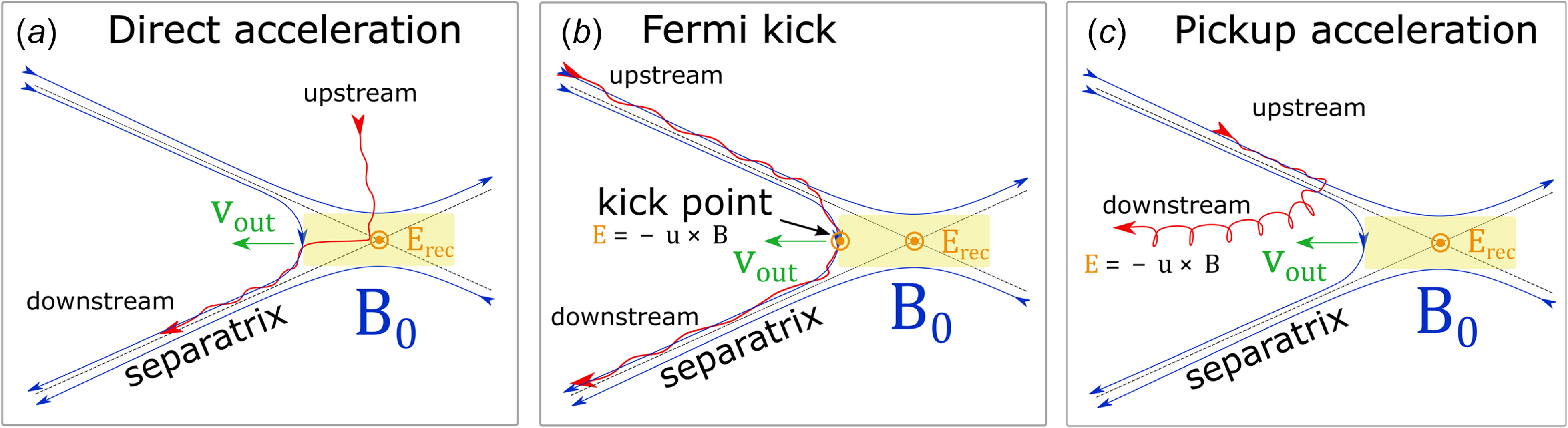


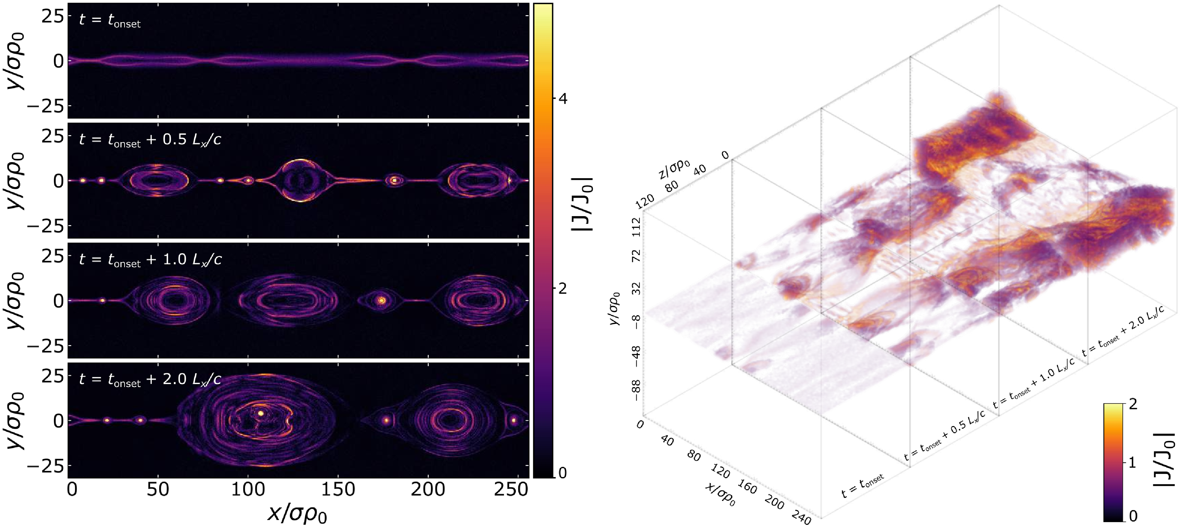


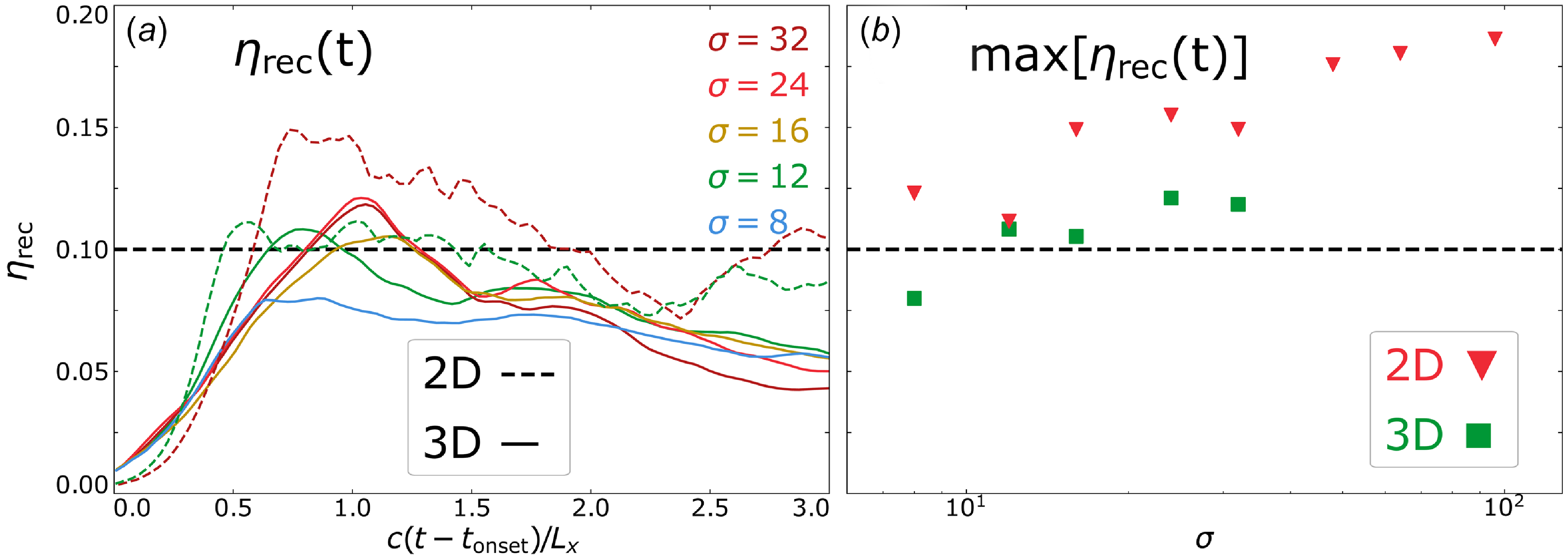

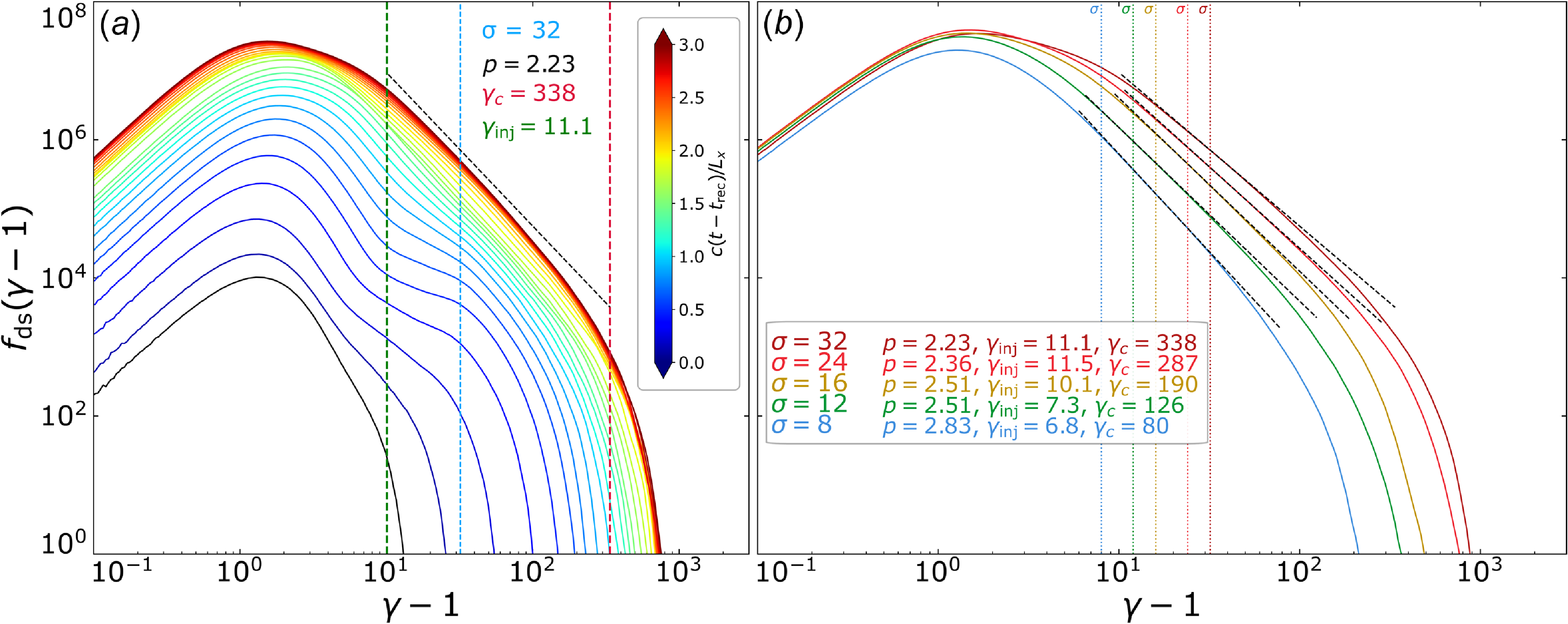


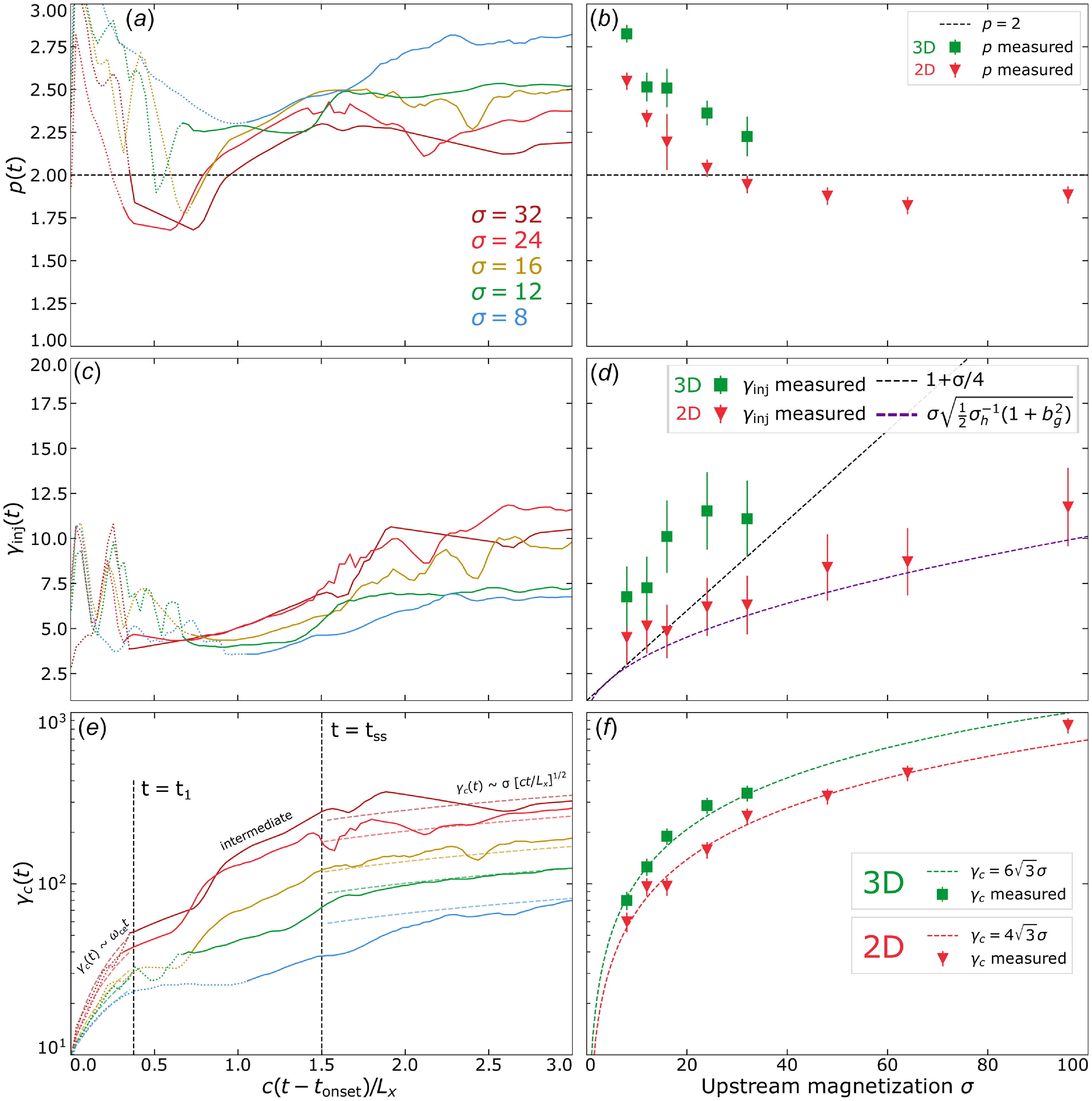


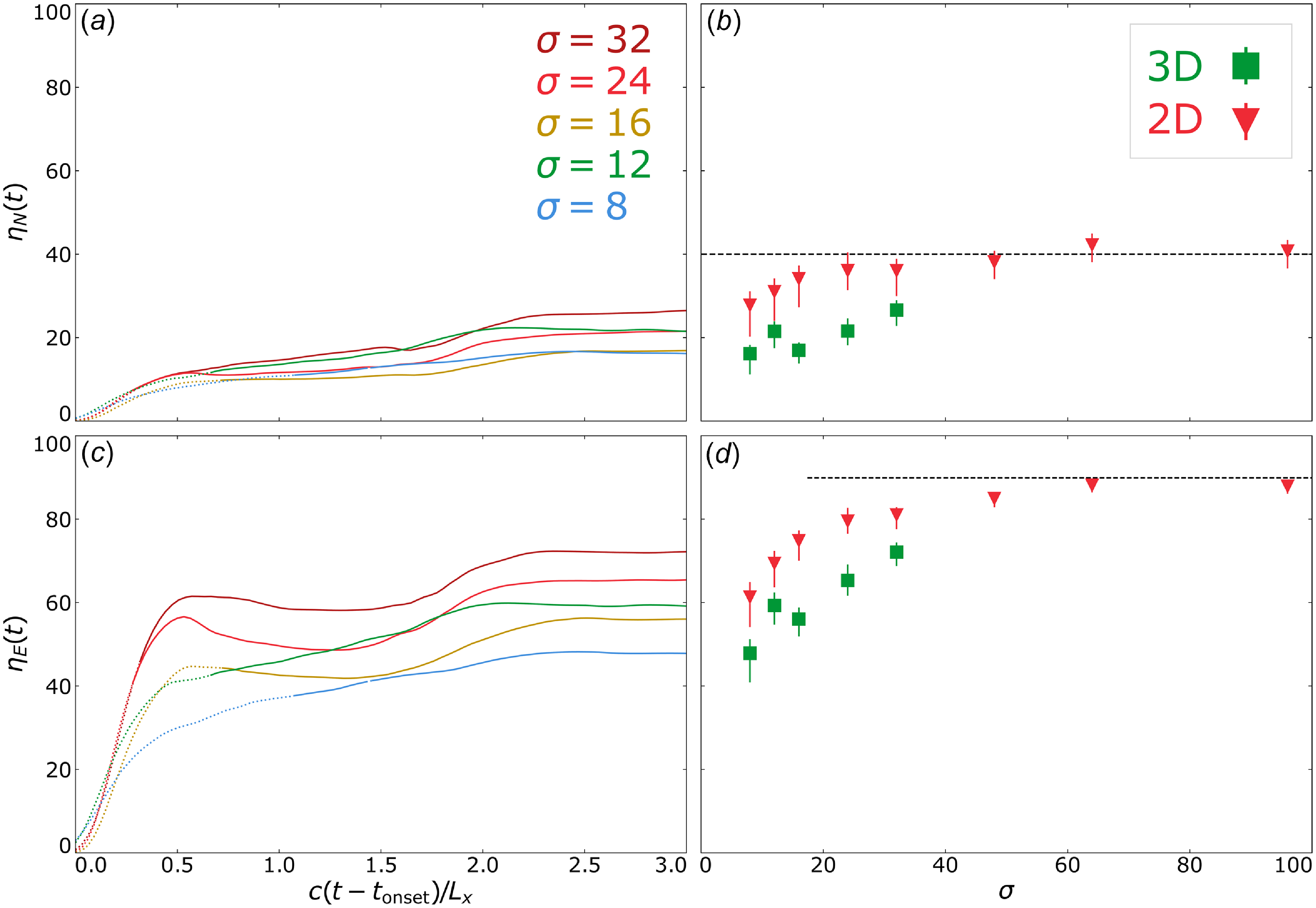


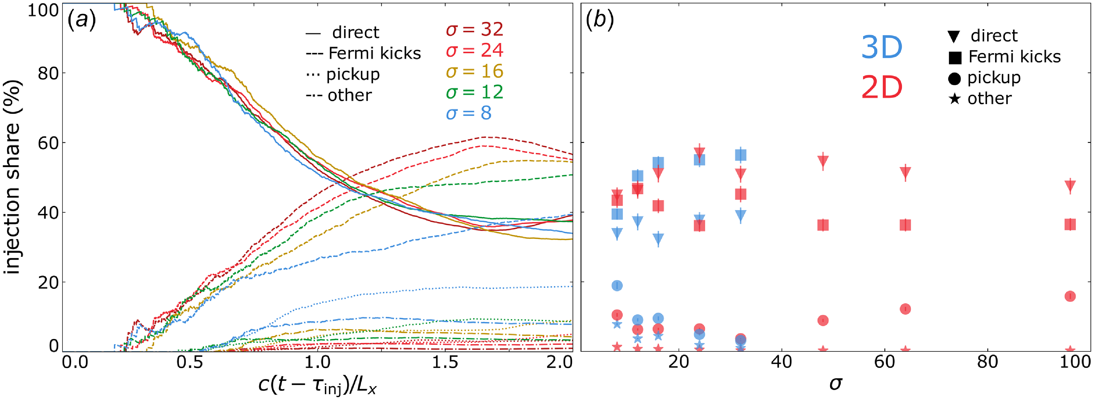


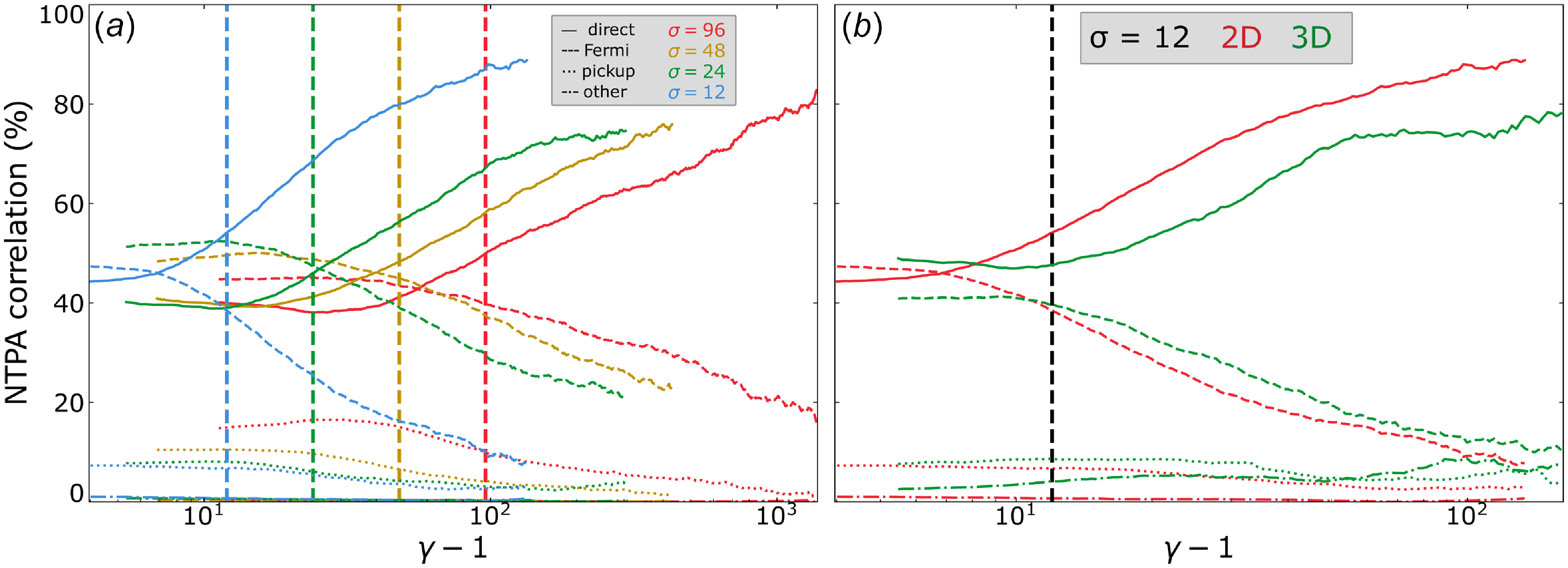


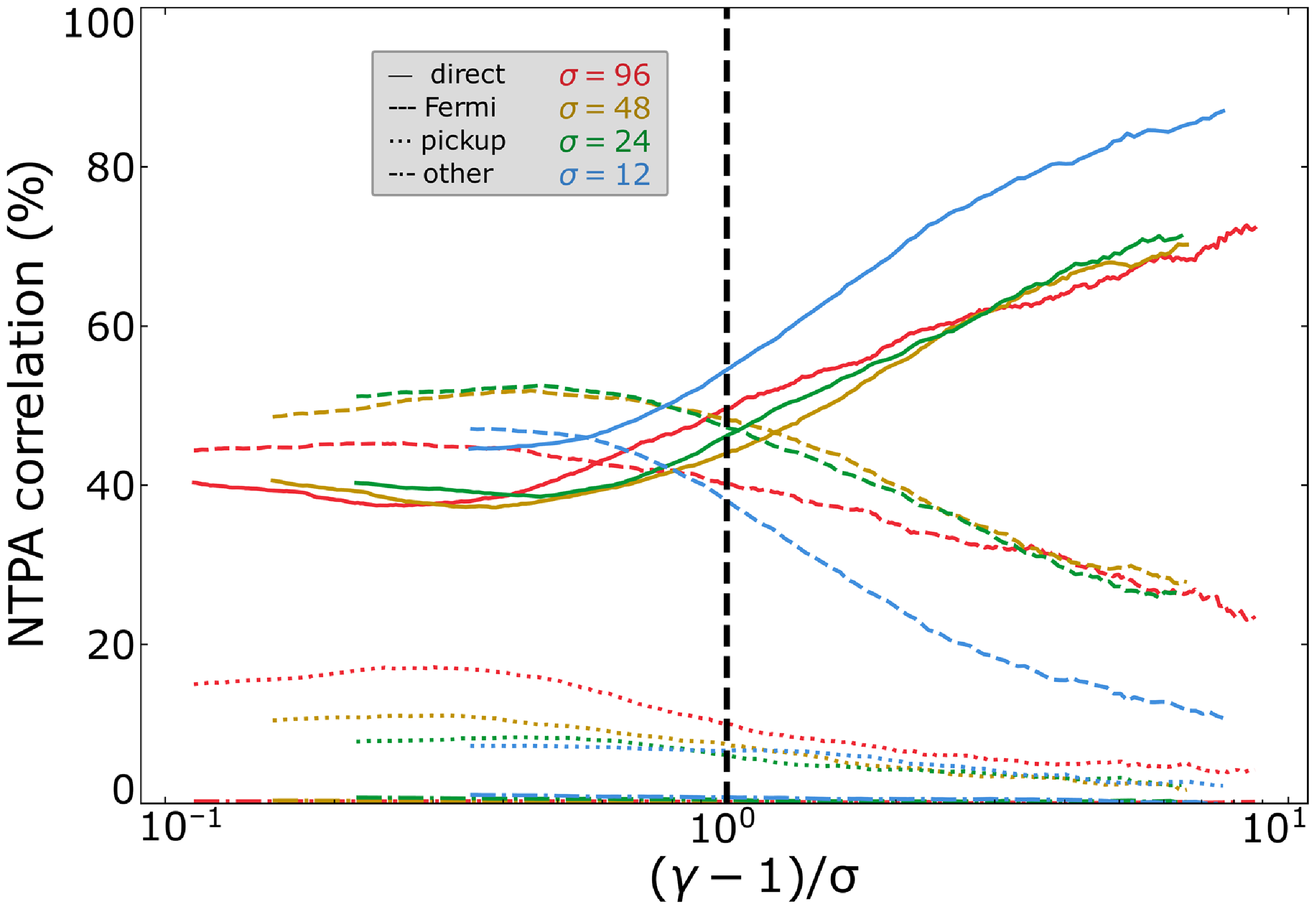


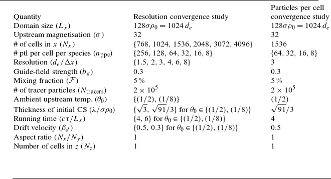
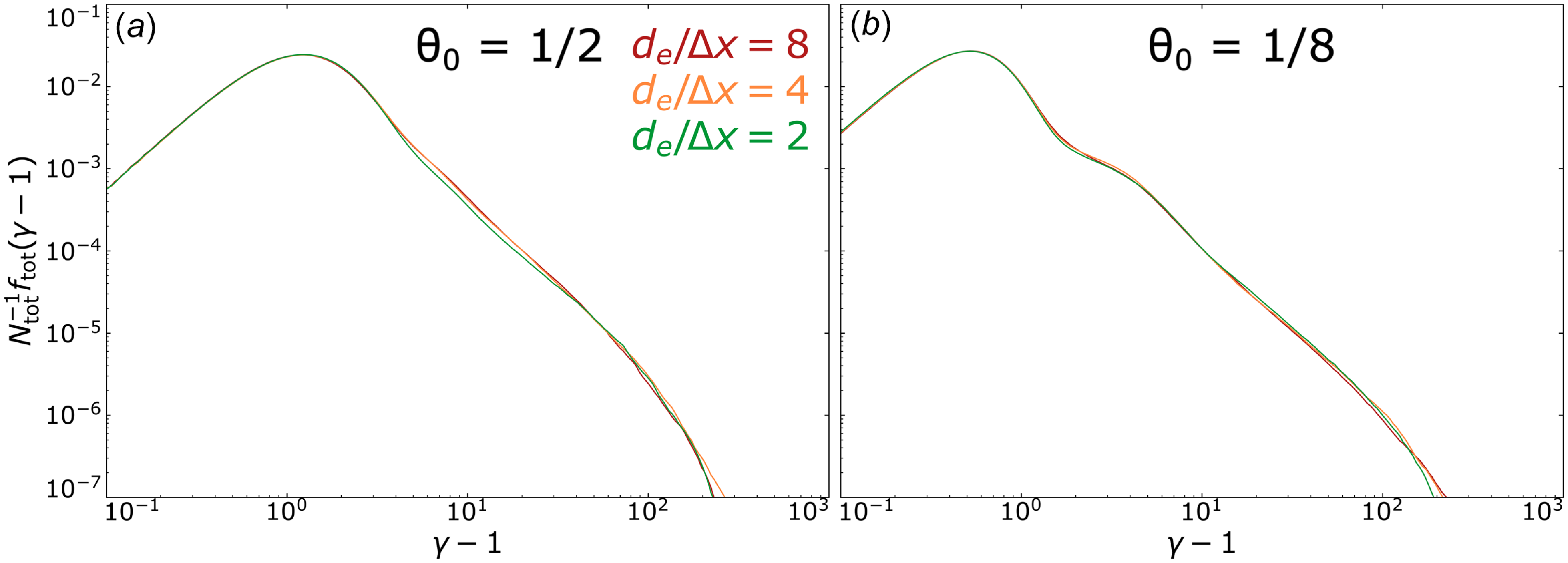


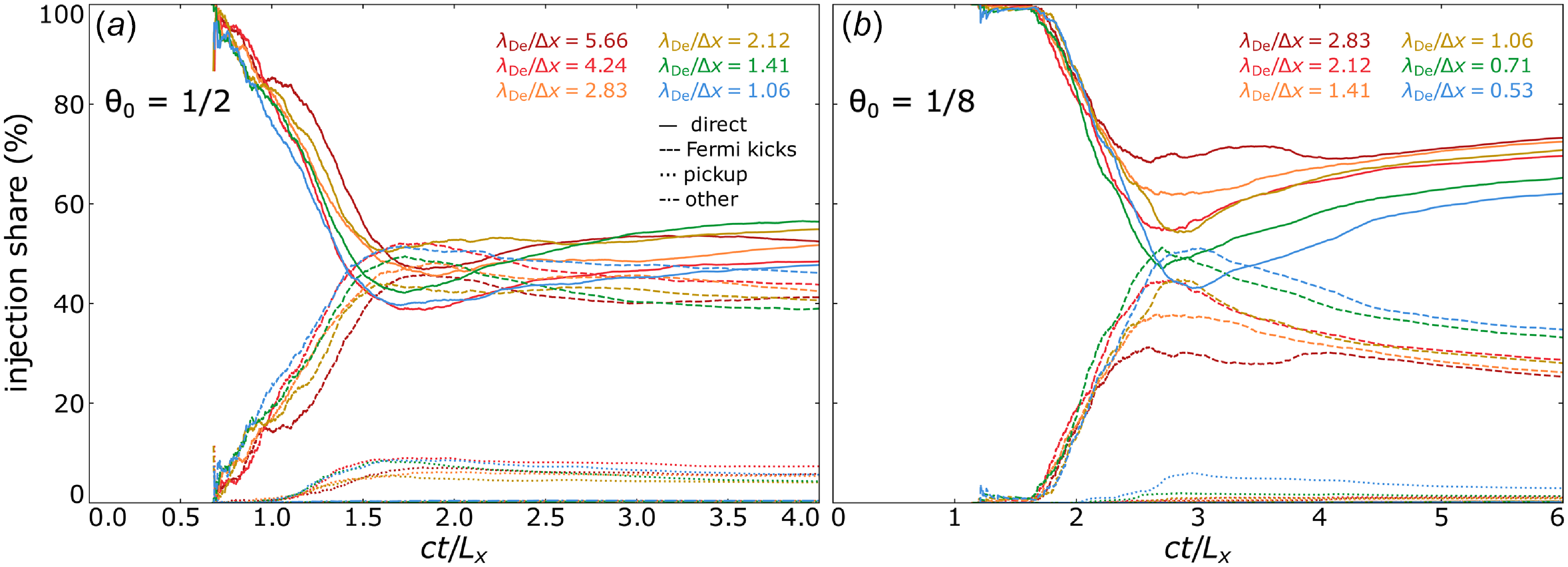


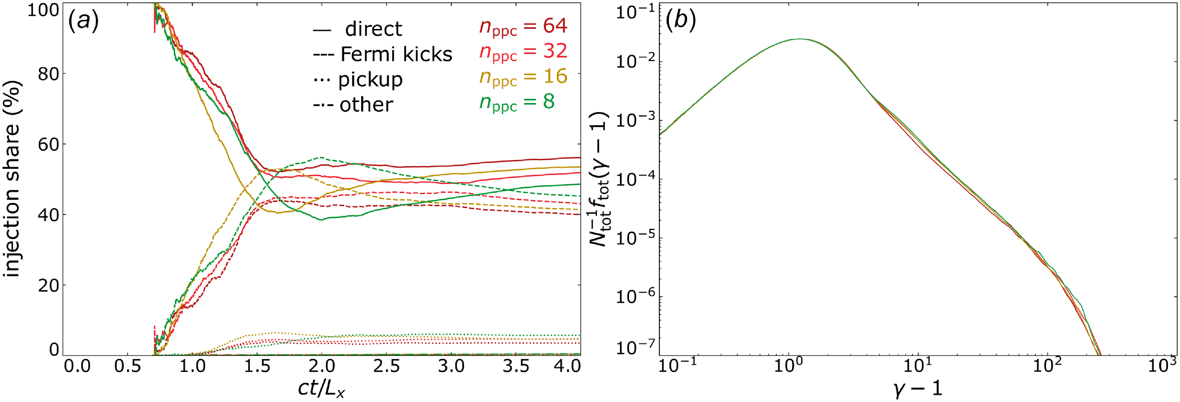


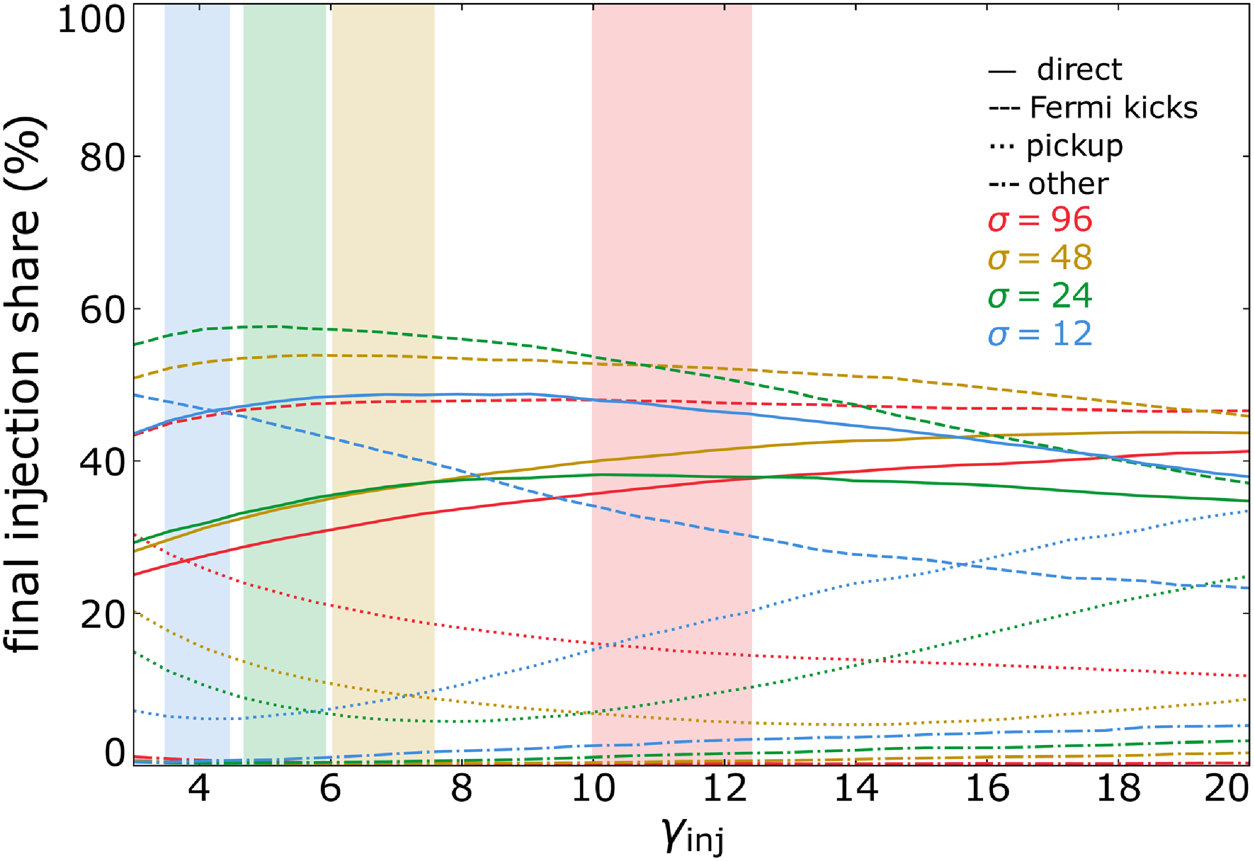


 Open access

