1. Introduction
Collision avoidance path planning is a fundamental technology in robotics and the foundation for robotic arm to complete complex work goals [Reference Xu, Zhou, Tan, Li, Ju and Peng1–Reference Trinh, Ekström and Cürüklü3]. In recent years, a large number of heuristic algorithms [Reference He, Liu, Chu, Negenborn and Wu4–Reference Fang and Liang6] such as the genetic algorithm, neural network algorithm, particle swarm algorithm, and A* algorithm have been implemented. The genetic algorithm is an algorithm based on the evolution of biological populations that are widely used in path planning problems [Reference Lei, Ming, Dunbing and Jingcao7, Reference Elhoseny, Tharwat and Hassanien8] due to its excellent real-time performance and global search capability. However, the genetic algorithm suffers from a slow convergence rate and a propensity to settle on local optimal solutions [Reference Rs, Db and Nc9, Reference Suresh, Venkatesan and Venugopal10]. The particle swarm algorithm is an optimization algorithm that simulates the flight of birds, with the benefits of fast convergence speed and simple implementation [Reference Kennedy and Eberhart11, Reference Tang, Zhu and Luo12]. However, the particle swarm algorithm is prone to premature and inaccurate convergence [Reference Jia, Wei, He and Zhang13, Reference Song, Wang and Zou14]. Neural network algorithm is an algorithm that mimics animal neural networks for distributed parallel information processing, which has the advantage of strong learning ability and robustness [Reference Hansen and Salamon15]. Nevertheless, the neural network algorithm has complex parameters, long running time, and slow convergence speed [Reference Miao, Chen, Yan and Wu16, Reference Pérez-Cutiño, Rodríguez, Pascual and Díaz-Báñez17]. The artificial potential field method proposed by Khatib is also utilized extensively in the field of obstacle avoidance in mobile robots and manipulators [Reference Khatib18]. Ge [Reference Ge and Cui19] proposed a new potential field method to apply mobile robots to path planning in dynamic environments. However, the artificial potential field method is prone to local optimization, making it challenging to apply broadly to the joint obstacle avoidance of multi-degree-of-freedom robotic arms. Hart [Reference Hart, Nilsson and Raphael20] proposed the A* algorithm in 1968 by designing a heuristic function, which has been widely utilized in path planning due to its low complexity, high search efficiency, and global optimality. Anshika [Reference Pal, Tiwari and Shukla21] proposed a modified A* algorithm applied to path planning for multi-robot systems that achieves the shortest route with the least amount of energy and generates the smoothest paths. Ren [Reference Ren, Song and Song22] proposed an A* algorithm based on the combination of the static weight method and jump point search, which decreases the number of visited nodes and improves the search efficiency. Guruji [Reference Guruji, Agarwal and Parsediya23] proposes an improved A* algorithm to determine the heuristic function before the collision phase, thereby reducing the search time enhancing the effectiveness of path planning. Li [Reference Li, Huang, Ding, Song and Lu24] incorporated the two-way alternating classification search strategy into the A* algorithm, which makes mobile robot path planning more efficient and smoother than the conventional A* algorithm. Zuo [Reference Zuo, Guo, Xu and Fu25] proposed a hierarchical path planning method combining the A* algorithm and the least squares policy iteration algorithm for mobile robot navigation in complex environments. The algorithm suffers from computational complexity and low environmental adaptability. Wang et al. [Reference Wang and Zhu26] proposed an A* algorithm with variable-step segment search, which can guarantee that the intermediate point is the optimal path. This algorithm is applied in obstacle avoidance path planning for a six-degree-of-freedom robotic arm, but it is less suitable for environments with complex obstacles. Bing et al. [Reference Bing, Lin and Zhou27] proposed a local path planning method that applies the A* algorithm, which first reduces the local path length by straightening the local path to achieve collision-free path planning for industrial robotic arms, but the algorithm does not take the obstacle avoidance method of the robotic arm linkage into account.
In addition to the need for a comprehensive approach to obstacle avoidance that takes into account the robotic arms’ end position and robotic arm linkage, the methods proposed in the literature [Reference Ren, Song and Song22–Reference Bing, Lin and Zhou27] frequently only improve the path search efficiency and path smoothing of the A* algorithm. For the end position and joint overall obstacle avoidance problem of a robotic arm, the majority of studies employ path planning algorithms for obstacle avoidance [Reference Newman and Branicky28–Reference Zhang, Zhang, Ma and Wang30]. However, these research methods are typically employed in simple obstacle avoidance environments, and only a few joint motions are considered to reduce the algorithmic complexity. In Section 4.2, a comparison between the approach proposed in this paper and the aforementioned concepts will be presented. The primary contribution of this paper is to propose a path planning method for overall 6-DOF robotic arms for obstacle avoidance in 3D environment based on an improved A* algorithm and artificial potential field method. First, an enhanced A* algorithm is proposed for robotic arm end path obstacle avoidance, followed by the development of a node collision detection method. The enhanced A* algorithm redefines the node search direction and proposes a local path optimization technique. Finally, the path nodes are smoothed by the cubic spline B-curve to enable the robotic arm to achieve continuous smooth path planning in the obstacle avoidance process. Notably, this paper is a continuation of previous research [Reference Xu, Zhou, Tan, Li, Ju and Peng1]. This method does not account for the obstacle avoidance of the robotic arm linkage. In this paper, the authors consider both end trajectory obstacle avoidance and robotic arm rod obstacle avoidance. Our main objective is to enable efficient path planning of a 6-DOF robotic arm in 3D environment to meet its obstacle avoidance requirements in certain motion environments.
The structure of the article is as follows: In Section 2, an enhanced A* algorithm for robotic arm end path planning is proposed. Based on this, a joint rod obstacle avoidance strategy for a 6-DOF robotic arm is designed in Section 3. In Section 4, simulations and experimentation are performed in detail. The final section provides a summary of the paper and its conclusions.
2. Improved A* algorithm for robotic arm end path planning
2.1. Traditional A* algorithm
The A* algorithm is a heuristic global optimal path planning algorithm that enables efficient path planning in an obstacle-aware environment [Reference Zhang, Zhang, Zeng and Li31]. The direction of the A* algorithm’s path search is determined by the cost function. In each round of path search, the cost function value of each child node in the vicinity of the parent node is calculated, and the child node with the smallest cost function value is chosen as the parent node in the next round. The final path result is then searched in this cycle. The cost function is typically expressed as follows:
 \begin{equation} F\!\left(n\right)=G\!\left(n\right)+H\!\left(n\right) \end{equation}
where $G(n)$
is the current path cost, which represents the cost of moving from the starting point to the child node, and
$G(n)$
is the current path cost, which represents the cost of moving from the starting point to the child node, and $H(n)$
is the heuristic function known as the estimated cost, which represents the cost of moving from the child node to the target point.
$H(n)$
is the heuristic function known as the estimated cost, which represents the cost of moving from the child node to the target point.
However, if the traditional A* algorithm is directly applied to the path planning of the robotic arm in 3D environment, the following three issues will arise: (1) The A* algorithm’s calculation speed in 3D environment will be drastically reduced; (2) when a node encounters obstacles, the A* algorithm’s search efficiency is drastically reduced; (3) the traditional A* algorithm treats the moving subject as a point and only considers whether the moving point collides with environmental obstacles. However, the position relationship between the robotic arm’s rod, the end position of the robotic arm, and the obstacles must be carefully considered when planning the robotic arm’s path.
Due to the above-mentioned shortcomings of the traditional A* algorithm in practical applications, this paper proposes an enhanced A* algorithm to apply the motion planning of the robotic arm to the known obstacle environment model. The enhanced A* algorithm first proposes a node collision detection method and then improves the efficiency of obstacle avoidance by refining the node search direction and enhancing the local path optimization.
2.2. Path nodes collision detection
An important factor for ensuring that nodes can search the environment without colliding with obstacles is the collision detection [Reference Wang, Tang, Dinesh and Tong32, Reference Liu, Qu, Xu, Du, Jia, Song and Liu33]. In this paper, all environmental obstacles are viewed as convex polyhedrons that undergo a particular expansion process, and the proposed algorithm can perceive the obstacles after the expansion. Since the search step size is relatively small compared to the polyhedral size of the obstacle, the essence of node and obstacle collision detection is to determine whether the node is located within this polyhedron. The plane ${\Omega} _{j}$
of the convex polyhedron
${\Omega} _{j}$
of the convex polyhedron ${\Omega}$
is arbitrarily extracted; the outward normal vector of the extracted plane
${\Omega}$
is arbitrarily extracted; the outward normal vector of the extracted plane ${\Omega} _{j}$
is the vector
${\Omega} _{j}$
is the vector $\overrightarrow{n}$
, and the point
$\overrightarrow{n}$
, and the point $p$
belongs to the plane
$p$
belongs to the plane ${\Omega} _{j}$
. The subsequent definitions are provided first:
${\Omega} _{j}$
. The subsequent definitions are provided first:
 \begin{equation} T\!\left(\Omega _{j},x\right)=\overrightarrow{n}\cdot \!\left(x-p\right) \end{equation}
where $x$
is the coordinate position of the current node.
$x$
is the coordinate position of the current node.
If $T\gt 0$
, it is defined that the node
$T\gt 0$
, it is defined that the node $x$
is located in the front area of the plane
$x$
is located in the front area of the plane ${\Omega} _{j}$
. If
${\Omega} _{j}$
. If $T=0$
, it is defined that point
$T=0$
, it is defined that point $x$
is located on the plane
$x$
is located on the plane ${\Omega} _{j}$
. If
${\Omega} _{j}$
. If $T\lt 0$
, it is defined that point
$T\lt 0$
, it is defined that point $x$
is located in the reverse area of the plane
$x$
is located in the reverse area of the plane ${\Omega} _{j}$
. For a clear illustration of the above definition, see Fig. 1. The node
${\Omega} _{j}$
. For a clear illustration of the above definition, see Fig. 1. The node $x$
is located in the front area of the plane
$x$
is located in the front area of the plane ${\Omega} _{1}$
and plane
${\Omega} _{1}$
and plane ${\Omega} _{2}$
in Fig. 1(a), and the node
${\Omega} _{2}$
in Fig. 1(a), and the node $x$
is located in the front area of the plane
$x$
is located in the front area of the plane ${\Omega} _{1}$
and the reverse area of plane
${\Omega} _{1}$
and the reverse area of plane ${\Omega} _{2}$
in Fig. 1(b).
${\Omega} _{2}$
in Fig. 1(b).
Discrimination of obstacle planes.

If for any plane ${\Omega} _{i}$
of the convex polyhedron
${\Omega} _{i}$
of the convex polyhedron ${\Omega}$
, the following equation exists:
${\Omega}$
, the following equation exists:
 \begin{equation} T\!\left(\Omega _{i},x\right)\lt 0 \end{equation}
Therefore, it means that the node $x$
is in the obstacle.
$x$
is in the obstacle.
2.3. Improved A* algorithm
When no obstacles are encountered, the search direction of the enhanced A* algorithm is the vector direction of the current node pointing to the goal point. The current node’s search direction is $\overline{v}$
, the current node is
$\overline{v}$
, the current node is $x$
, and the search step is
$x$
, and the search step is $d$
. Then, the search is performed on the child node
$d$
. Then, the search is performed on the child node $x'$
:
$x'$
:
 \begin{equation} x'=x+\overrightarrow{v}\cdot d \end{equation}
If the child node $x'$
interferes with the obstacle, the search cannot continue along the direction
$x'$
interferes with the obstacle, the search cannot continue along the direction $\overrightarrow{v}$
at the node
$\overrightarrow{v}$
at the node $x$
. Therefore, the search direction of the child nodes needs to be redefined. The front area plane of the current node
$x$
. Therefore, the search direction of the child nodes needs to be redefined. The front area plane of the current node $x$
is first selected from the obstacle
$x$
is first selected from the obstacle $O_{i}$
. Arbitrarily select a front area plane
$O_{i}$
. Arbitrarily select a front area plane $\Omega _{j}$
of the obstacle
$\Omega _{j}$
of the obstacle $O_{i}$
, take any edge
$O_{i}$
, take any edge $l_{k}$
from the plane
$l_{k}$
from the plane $\Omega _{j}$
, and take any point
$\Omega _{j}$
, and take any point $q$
on
$q$
on $l_{k}$
, then the cost value of the point
$l_{k}$
, then the cost value of the point $q$
can be expressed as follows:
$q$
can be expressed as follows:
 \begin{equation} F\!\left(q\right)=g\!\left(x\right)+h\!\left(q\right)+\!\left\| x-q\right\| \end{equation}
where $h(q)$
is the estimated cost value from the point
$h(q)$
is the estimated cost value from the point $q$
to the goal point,
$q$
to the goal point, $g(x)$
is the current cost value of the node
$g(x)$
is the current cost value of the node $x$
, and
$x$
, and $\| x-q\|$
is the path length value from node
$\| x-q\|$
is the path length value from node $x$
to point
$x$
to point $q$
.
$q$
.
Then, the point on $l_{k}$
where the smallest value of
$l_{k}$
where the smallest value of $F(q)$
exists is noted as
$F(q)$
exists is noted as $q_{k}$
.
$q_{k}$
. $q_{k}$
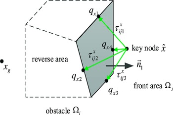
is denoted as a key node of the local path. Figure. 2 shows the search schematic.
$q_{k}$
is denoted as a key node of the local path. Figure. 2 shows the search schematic.
Schematic diagram of node search.

The node $\hat{x}$
will traverse all the edges on the frontal area plane
$\hat{x}$
will traverse all the edges on the frontal area plane ${\Omega} _{j}$
, and each edge will generate a key node, as shown in Fig. 3. If there are
${\Omega} _{j}$
, and each edge will generate a key node, as shown in Fig. 3. If there are $n$
boundaries on the front area plane
$n$
boundaries on the front area plane ${\Omega} _{j}, n$
alternative directions will be generated, denoted by
${\Omega} _{j}, n$
alternative directions will be generated, denoted by $\{\tau _{ij1}^{x_{1}},\tau _{ij2}^{x_{1}}\cdots \tau _{ijn}^{x_{1}}\}$
. The path cost values of
$\{\tau _{ij1}^{x_{1}},\tau _{ij2}^{x_{1}}\cdots \tau _{ijn}^{x_{1}}\}$
. The path cost values of $n$
directions are put into the set
$n$
directions are put into the set $c_{ij1}^{x_{1}}$
, and the minimum cost value in the set
$c_{ij1}^{x_{1}}$
, and the minimum cost value in the set $c_{ij1}^{x_{1}}$
is selected as the movement direction.
$c_{ij1}^{x_{1}}$
is selected as the movement direction.
Key nodes for the current node.

After locating the key node, the enhanced A* algorithm optimizes the local path based on the path nodes and the key node. The local path before the optimization is denoted by $\{K_{s},P_{1},P_{2},P_{3}\cdots P_{n-1},P_{n},K_{g}\}, K_{s},K_{g}$
denote the start point and goal point of the local path, respectively, and
$\{K_{s},P_{1},P_{2},P_{3}\cdots P_{n-1},P_{n},K_{g}\}, K_{s},K_{g}$
denote the start point and goal point of the local path, respectively, and $P_{1},P_{2},P_{3}\cdots P_{n-1},P_{n}$
denote the nodes of the path. The local path optimization process is as follows: Starting from the starting point
$P_{1},P_{2},P_{3}\cdots P_{n-1},P_{n}$
denote the nodes of the path. The local path optimization process is as follows: Starting from the starting point $K_{s}$
, connect
$K_{s}$
, connect $K_{s}$
to
$K_{s}$
to $P_{1}$
. If
$P_{1}$
. If $K_{s}$
and
$K_{s}$
and $P_{1}$
do not interfere with the obstacle, connect
$P_{1}$
do not interfere with the obstacle, connect $K_{s}$
and
$K_{s}$
and $P_{2}$
until
$P_{2}$
until $K_{s}$
and
$K_{s}$
and $P_{m} (k=3,4\cdots,m)$
interfere with the obstacle. Connect
$P_{m} (k=3,4\cdots,m)$
interfere with the obstacle. Connect $K_{s}$
to
$K_{s}$
to $P_{m-1}$
and clear all path nodes between the starting point
$P_{m-1}$
and clear all path nodes between the starting point $K_{s}$
and node
$K_{s}$
and node $P_{m-1}$
and update the path. Repeat this operation from the node
$P_{m-1}$
and update the path. Repeat this operation from the node $P_{m}$
until the key node
$P_{m}$
until the key node $K_{s}$
is searched. Figure 4 compares the situation before and following path optimization. Local path optimization can effectively reduce the path’s length and number of turns.
$K_{s}$
is searched. Figure 4 compares the situation before and following path optimization. Local path optimization can effectively reduce the path’s length and number of turns.
Comparison of paths before and after optimization.

3. Joint rod obstacle avoidance technique based on enhanced A* algorithm and artificial potential field method
During the process of path planning, the improved A* algorithm proposed above only modifies the position of the robotic arm’s end, while the robot arm posture is ignored. In this paper, the local optimization property of the artificial potential field method is used to ensure that the robotic arm rods do not collide with environmental obstacles by adjusting the robotic arm’s attitude.
3.1. Rod collision detection of the 6-DOF robotic arm
The robotic arm bars can be viewed as cylindrical features; therefore, it is necessary to determine if each cylindrical feature of the robotic arm bars collides with each environmental obstacle. The position of the robotic arm rod in space can be determined based on the robotic arm’s current pose. The current pose of the robot arm is $X=(x,y,z,\alpha,\beta,\gamma )$
, and the joint angle
$X=(x,y,z,\alpha,\beta,\gamma )$
, and the joint angle $Q_{X}=(q_{1},q_{2},q_{3},q_{4},q_{5},q_{6})$
can be obtained from the inverse kinematic model of the robot arm. As shown in Fig. 5(a), for the
$Q_{X}=(q_{1},q_{2},q_{3},q_{4},q_{5},q_{6})$
can be obtained from the inverse kinematic model of the robot arm. As shown in Fig. 5(a), for the $ith$
rod of the robot arm, the rod axis line segment is
$ith$
rod of the robot arm, the rod axis line segment is $l_{i}$
, the rod radius is
$l_{i}$
, the rod radius is $r_{i}$
, and the shortest distance from the line segment
$r_{i}$
, and the shortest distance from the line segment $l_{i}$
to the obstacle
$l_{i}$
to the obstacle $O_{j}$
is denoted by
$O_{j}$
is denoted by $D(l_{i},O_{j})$
. Then, the distance
$D(l_{i},O_{j})$
. Then, the distance $d_{ij}$
between the
$d_{ij}$
between the $ith$
rod of the robot arm and the
$ith$
rod of the robot arm and the $jth$
obstacle
$jth$
obstacle $O_{j}$
is expressed as follows:
$O_{j}$
is expressed as follows:
 \begin{equation} d_{ij}=\!\left\{\begin{array}{l@{\quad}l} D\!\left(l_{i},O_{j}\right)-r_{i} & D\!\left(l_{i},O_{j}\right)\gt r_{i}\\[5pt] \;\;\;\;\;\;\;0 & D\!\left(l_{i},O_{j}\right)\leq r \end{array}\right. \end{equation}
Distance between the robotic arm joint rod and the obstacle.

In this study, the distance between the robotic arm and the obstacle is calculated as follows: first, the linkage is simplified into spatial line segments, and then, the obstacle is inflated, as depicted in Fig. 5(b). Determine if there is a point of intersection between each linkage segment and the obstacle plane region. If an intersection point exists, the robotic arm will collide with the obstruction. Obtain the distance between the line segments of each link and the line segments comprising the obstacle plane if there is no intersection point. An illustration is provided below. Suppose that the endpoints of the $ith$
link of the robot arm are
$ith$
link of the robot arm are $q_{1}^{i}=(x_{1}^{i},y_{1}^{i},z_{1}^{i})$
and
$q_{1}^{i}=(x_{1}^{i},y_{1}^{i},z_{1}^{i})$
and $q_{2}^{i}=(x_{2}^{i},y_{2}^{i},z_{2}^{i})$
. Then,
$q_{2}^{i}=(x_{2}^{i},y_{2}^{i},z_{2}^{i})$
. Then, $ith$
link can be regarded as a line segment
$ith$
link can be regarded as a line segment $\overline{q_{1}^{i}q_{2}^{i}}$
. Assume that the plane region is enclosed by points
$\overline{q_{1}^{i}q_{2}^{i}}$
. Assume that the plane region is enclosed by points $\overrightarrow{p}_{\!\!1}\overrightarrow{p}_{\!\!2}\cdots \overrightarrow{p}_{\!\!n}\overrightarrow{p}_{\!\!1}$
connected in counterclockwise order. Suppose the normal vector of the plane is vector
$\overrightarrow{p}_{\!\!1}\overrightarrow{p}_{\!\!2}\cdots \overrightarrow{p}_{\!\!n}\overrightarrow{p}_{\!\!1}$
connected in counterclockwise order. Suppose the normal vector of the plane is vector $(A,B,C)$
, the equation of the plane is given below:
$(A,B,C)$
, the equation of the plane is given below:
 \begin{equation} Ax+By+Cz+D=0 \end{equation}
Substitution of the coordinates $q_{1}^{i}=(x_{1}^{i},y_{1}^{i},z_{1}^{i})$
and
$q_{1}^{i}=(x_{1}^{i},y_{1}^{i},z_{1}^{i})$
and $q_{2}^{i}=(x_{2}^{i},y_{2}^{i},z_{2}^{i})$
of the endpoints of the segment into the above equation yields:
$q_{2}^{i}=(x_{2}^{i},y_{2}^{i},z_{2}^{i})$
of the endpoints of the segment into the above equation yields:
 \begin{equation} d_{1}^{i}=Ax_{1}^{i}+By_{1}^{i}+Cz_{1}^{i}+D \end{equation}
 \begin{equation} d_{2}^{i}=Ax_{2}^{i}+By_{2}^{i}+Cz_{2}^{i}+D \end{equation}
If $d_{1}^{i}$
and
$d_{1}^{i}$
and $d_{2}^{i}$
have the same sign, then there is no intersection of line
$d_{2}^{i}$
have the same sign, then there is no intersection of line $\overline{q_{1}^{i}q_{2}^{i}}$
with the plane, and there is no collision between that line and the obstacle. If
$\overline{q_{1}^{i}q_{2}^{i}}$
with the plane, and there is no collision between that line and the obstacle. If $d_{1}^{i}$
and
$d_{1}^{i}$
and $d_{2}^{i}$
have opposite signs, then there is an intersection of line
$d_{2}^{i}$
have opposite signs, then there is an intersection of line $\overline{q_{1}^{i}q_{2}^{i}}$
with the plane, and it is easy to solve for the location of the intersection. Since the plane region
$\overline{q_{1}^{i}q_{2}^{i}}$
with the plane, and it is easy to solve for the location of the intersection. Since the plane region $\overrightarrow{p}_{\!\!1}\overrightarrow{p}_{\!\!2}\cdots \overrightarrow{p}_{n}\overrightarrow{p}_{\!\!1}$
mentioned in this study is only a small part of the whole plane, when there is an intersection of the line segment with the whole plane, there may be a situation where the line segment
$\overrightarrow{p}_{\!\!1}\overrightarrow{p}_{\!\!2}\cdots \overrightarrow{p}_{n}\overrightarrow{p}_{\!\!1}$
mentioned in this study is only a small part of the whole plane, when there is an intersection of the line segment with the whole plane, there may be a situation where the line segment $\overline{q_{1}^{i}q_{2}^{i}}$
does not intersect with the plane region
$\overline{q_{1}^{i}q_{2}^{i}}$
does not intersect with the plane region $\overrightarrow{p}_{\!\!1}\overrightarrow{p}_{\!\!2}\cdots \overrightarrow{p}_{n}\overrightarrow{p}_{\!\!1}$
. Therefore, it is necessary to determine whether the intersection point is in the plane area. To better illustrate the judgment of whether the intersection point is in the plane region
$\overrightarrow{p}_{\!\!1}\overrightarrow{p}_{\!\!2}\cdots \overrightarrow{p}_{n}\overrightarrow{p}_{\!\!1}$
. Therefore, it is necessary to determine whether the intersection point is in the plane area. To better illustrate the judgment of whether the intersection point is in the plane region $\overrightarrow{p}_{\!\!1}\overrightarrow{p}_{\!\!2}\cdots \overrightarrow{p}_{n}\overrightarrow{p}_{\!\!1}$
, Fig. 6 is depicted below.
$\overrightarrow{p}_{\!\!1}\overrightarrow{p}_{\!\!2}\cdots \overrightarrow{p}_{n}\overrightarrow{p}_{\!\!1}$
, Fig. 6 is depicted below.
Schematic diagram for judging the intersection point.

The shortest distance between a line segment and a planar region.

Assume that the intersection point is $o$
. The points
$o$
. The points $p_{1}p_{2}\cdots p_{n}$
are forming the planar region form the vectors
$p_{1}p_{2}\cdots p_{n}$
are forming the planar region form the vectors $\overrightarrow{p_{1}p_{2}},\; \overrightarrow{p_{2}p_{3}},\; \overrightarrow{p_{3}p_{4}}$
and
$\overrightarrow{p_{1}p_{2}},\; \overrightarrow{p_{2}p_{3}},\; \overrightarrow{p_{3}p_{4}}$
and $\overrightarrow{p_{4}p_{5}}$
in order, and the vertices form the vectors
$\overrightarrow{p_{4}p_{5}}$
in order, and the vertices form the vectors $\overrightarrow{p_{1}o},\; \overrightarrow{p_{2}o},\; \overrightarrow{p_{3}o},\; \overrightarrow{p_{4}o}$
and
$\overrightarrow{p_{1}o},\; \overrightarrow{p_{2}o},\; \overrightarrow{p_{3}o},\; \overrightarrow{p_{4}o}$
and $\overrightarrow{p_{4}o}$
with the point
$\overrightarrow{p_{4}o}$
with the point $o$
, respectively, and satisfy the following equation:
$o$
, respectively, and satisfy the following equation:
 \begin{equation} \overrightarrow{p_{i}p_{i+1}}\times \overrightarrow{p_{i}o}=m_{i}\quad,\,i=1\sim n \end{equation}
According to the above equation, the vector $\overrightarrow{p_{i}p_{i+1}}$
, formed between the vertices of the plane region and the vector
$\overrightarrow{p_{i}p_{i+1}}$
, formed between the vertices of the plane region and the vector $\overrightarrow{p_{i}o}$
(formed by the vertices and the intersection point) is multiplied.
$\overrightarrow{p_{i}o}$
(formed by the vertices and the intersection point) is multiplied.
If the sign of the results of the calculation is the same, then the intersection point is in the plane region, and line segment $\overline{q_{1}^{i}q_{2}^{i}}$
, must collide with the obstacle region. On the contrary, the intersection point is outside the plane region, then the line segment
$\overline{q_{1}^{i}q_{2}^{i}}$
, must collide with the obstacle region. On the contrary, the intersection point is outside the plane region, then the line segment $\overline{q_{1}^{i}q_{2}^{i}}$
will not collide with the obstacle region. When no collision occurs, solve for the distance between line segment
$\overline{q_{1}^{i}q_{2}^{i}}$
will not collide with the obstacle region. When no collision occurs, solve for the distance between line segment $\overline{q_{1}^{i}q_{2}^{i}}$
and line segment
$\overline{q_{1}^{i}q_{2}^{i}}$
and line segment $\overline{p_{1}p_{2}}, \overline{p_{2}p_{3}}, \overline{p_{3}p_{4}}, \overline{p_{4}p_{5}}, \overline{p_{1}p_{3}}, \overline{p_{1}p_{4}}, \overline{p_{2}p_{4}}$
and
$\overline{p_{1}p_{2}}, \overline{p_{2}p_{3}}, \overline{p_{3}p_{4}}, \overline{p_{4}p_{5}}, \overline{p_{1}p_{3}}, \overline{p_{1}p_{4}}, \overline{p_{2}p_{4}}$
and $\overline{p_{2}p_{5}}$
, respectively. The line segments of each link of the robot arm and the obstacle plane are evaluated sequentially to determine if an intersection point exists. If there is no intersection point, calculate the distance between the arm and the obstacle and take the smallest value as the shortest distance.
$\overline{p_{2}p_{5}}$
, respectively. The line segments of each link of the robot arm and the obstacle plane are evaluated sequentially to determine if an intersection point exists. If there is no intersection point, calculate the distance between the arm and the obstacle and take the smallest value as the shortest distance.
The detailed calculation of the shortest distance between the rod of the robotic arm and the obstacle is provided below. The shortest distance between the line segment $\overline{q_{1}^{i}q_{2}^{i}}$
and each planar region of the obstacle is solved separately. An example of the shortest distance between the line segment
$\overline{q_{1}^{i}q_{2}^{i}}$
and each planar region of the obstacle is solved separately. An example of the shortest distance between the line segment $\overline{q_{1}^{i}q_{2}^{i}}$
and the plane region
$\overline{q_{1}^{i}q_{2}^{i}}$
and the plane region $\overrightarrow{p}_{\!\!1}\overrightarrow{p}_{\!\!2}\overrightarrow{p}_{\!\!3}\overrightarrow{p}_{\!\!4}\overrightarrow{p}_{\!\!5}\overrightarrow{p}_{\!\!1}$
is shown in Fig. 7. In essence, the goal is to find the minimum value of the shortest distance between the line segment
$\overrightarrow{p}_{\!\!1}\overrightarrow{p}_{\!\!2}\overrightarrow{p}_{\!\!3}\overrightarrow{p}_{\!\!4}\overrightarrow{p}_{\!\!5}\overrightarrow{p}_{\!\!1}$
is shown in Fig. 7. In essence, the goal is to find the minimum value of the shortest distance between the line segment $\overline{q_{1}^{i}q_{2}^{i}}$
and each of line segments
$\overline{q_{1}^{i}q_{2}^{i}}$
and each of line segments $\overline{p_{1}p_{2}}, \overline{p_{2}p_{3}}, \overline{p_{3}p_{4}}, \overline{p_{4}p_{5}}, \overline{p_{5}p_{1}}, \overline{p_{1}p_{3}}, \overline{p_{1}p_{4}}, \overline{p_{2}p_{4}}$
and
$\overline{p_{1}p_{2}}, \overline{p_{2}p_{3}}, \overline{p_{3}p_{4}}, \overline{p_{4}p_{5}}, \overline{p_{5}p_{1}}, \overline{p_{1}p_{3}}, \overline{p_{1}p_{4}}, \overline{p_{2}p_{4}}$
and $\overline{p_{2}p_{5}}$
on the plane region
$\overline{p_{2}p_{5}}$
on the plane region $\overrightarrow{p}_{\!\!1}\overrightarrow{p}_{\!\!2}\overrightarrow{p}_{\!\!3}\overrightarrow{p}_{\!\!4}\overrightarrow{p}_{\!\!5}\overrightarrow{p}_{\!\!1}$
as the shortest distance between the line segment and the plane region. It is noteworthy that the shortest distance between line segment
$\overrightarrow{p}_{\!\!1}\overrightarrow{p}_{\!\!2}\overrightarrow{p}_{\!\!3}\overrightarrow{p}_{\!\!4}\overrightarrow{p}_{\!\!5}\overrightarrow{p}_{\!\!1}$
as the shortest distance between the line segment and the plane region. It is noteworthy that the shortest distance between line segment $\overline{q_{1}^{i}q_{2}^{i}}$
and line segments
$\overline{q_{1}^{i}q_{2}^{i}}$
and line segments $\overline{p_{1}p_{3}}, \overline{p_{1}p_{4}}, \overline{p_{2}p_{4}}$
and
$\overline{p_{1}p_{3}}, \overline{p_{1}p_{4}}, \overline{p_{2}p_{4}}$
and $\overline{p_{2}p_{5}}$
is necessary for this calculation. In general, the obstacle is relatively small compared to the rod of the robotic arm. Consequently, the shortest distance between the line segment of the rod of the robotic arm and the plane region of the obstacle often falls on the line segment that encloses the flat plane region, such as the shortest distance
$\overline{p_{2}p_{5}}$
is necessary for this calculation. In general, the obstacle is relatively small compared to the rod of the robotic arm. Consequently, the shortest distance between the line segment of the rod of the robotic arm and the plane region of the obstacle often falls on the line segment that encloses the flat plane region, such as the shortest distance $| pq|$
in Fig. 7(a). However, under certain conditions, the shortest distance between the line segment of the rod and the plane region of the obstacle can lie within the plane region of the obstacle, such as the shortest distance
$| pq|$
in Fig. 7(a). However, under certain conditions, the shortest distance between the line segment of the rod and the plane region of the obstacle can lie within the plane region of the obstacle, such as the shortest distance $| pq|$
in Fig. 7(b). Therefore, solving for the shortest distance between rod segment
$| pq|$
in Fig. 7(b). Therefore, solving for the shortest distance between rod segment $\overline{q_{1}^{i}q_{2}^{i}}$
and line segments
$\overline{q_{1}^{i}q_{2}^{i}}$
and line segments $\overline{p_{1}p_{3}}, \overline{p_{1}p_{4}}$
and
$\overline{p_{1}p_{3}}, \overline{p_{1}p_{4}}$
and $\overline{p_{2}p_{4}}$
can help reduce the calculation errors in a few cases.
$\overline{p_{2}p_{4}}$
can help reduce the calculation errors in a few cases.
Here is an example of solving for the shortest distance between line segment $\overline{q_{1}^{i}q_{2}^{i}}$
and line segment
$\overline{q_{1}^{i}q_{2}^{i}}$
and line segment $\overline{p_{1}p_{2}}$
. The coordinates of points
$\overline{p_{1}p_{2}}$
. The coordinates of points $q_{1}^{i}, q_{2}^{i}, p_{1}$
and
$q_{1}^{i}, q_{2}^{i}, p_{1}$
and $p_{2}$
are
$p_{2}$
are $(x_{{q_{1}}},y_{{q_{1}}},z_{{q_{1}}}), (x_{{q_{2}}},y_{{q_{2}}},z_{{q_{2}}}), (x_{{p_{1}}},y_{{p_{1}}},z_{{p_{1}}})$
and
$(x_{{q_{1}}},y_{{q_{1}}},z_{{q_{1}}}), (x_{{q_{2}}},y_{{q_{2}}},z_{{q_{2}}}), (x_{{p_{1}}},y_{{p_{1}}},z_{{p_{1}}})$
and $(x_{{p_{2}}},y_{{p_{2}}},z_{{p_{2}}})$
, respectively. Assuming
$(x_{{p_{2}}},y_{{p_{2}}},z_{{p_{2}}})$
, respectively. Assuming $q$
is a point on the line
$q$
is a point on the line $q_{1}^{i}q_{2}^{i}$
; then, the coordinates of point
$q_{1}^{i}q_{2}^{i}$
; then, the coordinates of point $q$
can be described as follows:
$q$
can be described as follows:
 \begin{equation} \!\left\{\begin{array}{l} x_{q}=x_{{q_{1}}}+s\!\left(x_{{q_{2}}}-x_{{q_{1}}}\right)\\[5pt] y_{q}=y_{{q_{1}}}+s\!\left(y_{{q_{2}}}-y_{{q_{1}}}\right)\\[5pt] z_{q}=z_{{q_{1}}}+s\!\left(z_{{q_{2}}}-z_{{q_{1}}}\right) \end{array}\right. \end{equation}
When there exists $0\leq s\leq 1, q$
is a point on line segment
$0\leq s\leq 1, q$
is a point on line segment $\overline{q_{1}^{i}q_{2}^{i}}$
. Conversely,
$\overline{q_{1}^{i}q_{2}^{i}}$
. Conversely, $q$
is a point on the extension of the line segment
$q$
is a point on the extension of the line segment $\overline{q_{1}^{i}q_{2}^{i}}$
.
$\overline{q_{1}^{i}q_{2}^{i}}$
.
Similarly, letting $p$
be a point on the line
$p$
be a point on the line $p_{1}p_{2}$
, the coordinates of the point
$p_{1}p_{2}$
, the coordinates of the point $p$
can be described as follows:
$p$
can be described as follows:
 \begin{equation} \!\left\{\begin{array}{l} x_{p}=x_{{p_{1}}}+t\!\left(x_{{p_{2}}}-x_{{p_{1}}}\right)\\[5pt] y_{p}=y_{{p_{1}}}+t\!\left(y_{{p_{2}}}-y_{{p_{1}}}\right)\\[5pt] z_{p}=z_{{p_{1}}}+t\!\left(z_{{p_{2}}}-z_{{p_{1}}}\right) \end{array}\right. \end{equation}
When there exists $0\leq t\leq 1, p$
is a point on line segment
$0\leq t\leq 1, p$
is a point on line segment $\overline{p_{1}p_{2}}$
. Conversely,
$\overline{p_{1}p_{2}}$
. Conversely, $p$
is a point on the extension of line segment
$p$
is a point on the extension of line segment $\overline{p_{1}p_{2}}$
.
$\overline{p_{1}p_{2}}$
.
Thus, the distance between points $p$
and
$p$
and $q$
can be expressed as:
$q$
can be expressed as:
 \begin{equation} \!\left| pq\right| =\sqrt{\!\left(x_{q}-x_{p}\right)^{2}+\!\left(y_{q}-y_{p}\right)^{2}+\!\left(z_{q}-z_{p}\right)^{2}} \end{equation}
Solving for the shortest distance between line segment $\overline{q_{1}^{i}q_{2}^{i}}$
and line segment
$\overline{q_{1}^{i}q_{2}^{i}}$
and line segment $\overline{p_{1}p_{2}}$
is equivalent to solving for the shortest distance between the points
$\overline{p_{1}p_{2}}$
is equivalent to solving for the shortest distance between the points $p$
and
$p$
and $q$
. The function can be set up as follows:
$q$
. The function can be set up as follows:
 \begin{equation} f\!\left(s,t\right)=\!\left| pq\right| ^{2}=\!\left(x_{q}-x_{p}\right)^{2}+\!\left(y_{q}-y_{p}\right)^{2}+\!\left(z_{q}-z_{p}\right)^{2} \end{equation}
Calculate the partial derivative of the function $f(s,t)$
and compute the following equation:
$f(s,t)$
and compute the following equation:
 \begin{equation} \!\left\{\begin{array}{l} \dfrac{\partial f\!\left(s,t\right)}{\partial s}=0\\[10pt] \dfrac{\partial f\!\left(s,t\right)}{\partial t}=0 \end{array}\right. \end{equation}
If the solutions $s$
and
$s$
and $t$
of the above equation satisfy the following equation:
$t$
of the above equation satisfy the following equation:
 \begin{equation} \!\left\{\begin{array}{l} 0\leq s\leq 1\\[5pt] 0\leq t\leq 1 \end{array}\right. \end{equation}
It can be determined that $p$
is on line segment
$p$
is on line segment $\overline{p_{1}p_{2}}$
and
$\overline{p_{1}p_{2}}$
and $q$
is on line segment
$q$
is on line segment $q$
. The distance
$q$
. The distance $| pq|$
can be obtained by solving the equations mentioned above.
$| pq|$
can be obtained by solving the equations mentioned above.
If Eq. (16) is not satisfied, then it is calculated as follows: If $s\gt 1$
, then the value of
$s\gt 1$
, then the value of $s$
is 1, and the value of point
$s$
is 1, and the value of point $p$
is
$p$
is $p_{2}$
. If
$p_{2}$
. If $s\lt 0$
, then the value of
$s\lt 0$
, then the value of $s$
is 0, and the value of point
$s$
is 0, and the value of point $p$
is
$p$
is $p_{1}$
. The problem mentioned above can be transformed into the shortest distance from point
$p_{1}$
. The problem mentioned above can be transformed into the shortest distance from point $p$
to line segment
$p$
to line segment $\overline{q_{1}^{i}q_{2}^{i}}$
. Consequently, Eq. (4) is transformed into the following function:
$\overline{q_{1}^{i}q_{2}^{i}}$
. Consequently, Eq. (4) is transformed into the following function:
 \begin{equation} f\!\left(t\right)=\!\left| pq\right| ^{2}=\!\left(x_{q}-x_{p}\right)^{2}+\!\left(y_{q}-y_{p}\right)^{2}+\!\left(z_{q}-z_{p}\right)^{2} \end{equation}
Solve for the derivative of the function $f(t)$
and compute the following equation:
$f(t)$
and compute the following equation:
 \begin{equation} \frac{df\!\left(t\right)}{dt}=0 \end{equation}
If $t\gt 1$
, then the value of
$t\gt 1$
, then the value of $t$
is 1, and the value of point
$t$
is 1, and the value of point $q$
is
$q$
is $q_{1}^{i}$
. If
$q_{1}^{i}$
. If $t\lt 0$
, then the value of
$t\lt 0$
, then the value of $t$
is 0 and the value of point
$t$
is 0 and the value of point $q$
is
$q$
is $q_{2}^{i}$
. The distance between points
$q_{2}^{i}$
. The distance between points $p$
and
$p$
and $q$
can be calculated by Eq. (13), which is also the shortest distance between line segments
$q$
can be calculated by Eq. (13), which is also the shortest distance between line segments $\overline{p_{1}p_{2}}$
and
$\overline{p_{1}p_{2}}$
and $\overline{q_{1}^{i}q_{2}^{i}}$
.
$\overline{q_{1}^{i}q_{2}^{i}}$
.
Finally, the method outlined above is applied to calculate the shortest distance between the line segment $\overline{q_{1}^{i}q_{2}^{i}}$
and each line segment of the plane region
$\overline{q_{1}^{i}q_{2}^{i}}$
and each line segment of the plane region $\overrightarrow{p}_{\!1}\overrightarrow{p}_{\!2}\overrightarrow{p}_{\!3}\overrightarrow{p}_{\!4}\overrightarrow{p}_{\!5}\overrightarrow{p}_{\!1}$
. The smallest of these distances is then considered the shortest distance between the line segment
$\overrightarrow{p}_{\!1}\overrightarrow{p}_{\!2}\overrightarrow{p}_{\!3}\overrightarrow{p}_{\!4}\overrightarrow{p}_{\!5}\overrightarrow{p}_{\!1}$
. The smallest of these distances is then considered the shortest distance between the line segment $\overline{q_{1}^{i}q_{2}^{i}}$
and the plane region
$\overline{q_{1}^{i}q_{2}^{i}}$
and the plane region $\overrightarrow{p}_{\!1}\overrightarrow{p}_{\!2}\overrightarrow{p}_{\!3}\overrightarrow{p}_{\!4}\overrightarrow{p}_{\!5}\overrightarrow{p}_{\!1}$
. Following the same procedure, the shortest distance between the line segment
$\overrightarrow{p}_{\!1}\overrightarrow{p}_{\!2}\overrightarrow{p}_{\!3}\overrightarrow{p}_{\!4}\overrightarrow{p}_{\!5}\overrightarrow{p}_{\!1}$
. Following the same procedure, the shortest distance between the line segment $\overline{q_{1}^{i}q_{2}^{i}}$
and each plane of the obstacle is calculated, and the smallest value among these distances represents the shortest distance between the line segment
$\overline{q_{1}^{i}q_{2}^{i}}$
and each plane of the obstacle is calculated, and the smallest value among these distances represents the shortest distance between the line segment $\overline{q_{1}^{i}q_{2}^{i}}$
and the obstacle.
$\overline{q_{1}^{i}q_{2}^{i}}$
and the obstacle.
Overall obstacle avoidance strategy of the robotic arm.

Path planning in Environment 1. (a) Traditional A*, (b) improved A*

Path planning in Environment 2. (a) Traditional A*, (b) improved A*

Path planning in Environment 3. (a) Traditional A*, (b) improved A*

Path planning in Environment 4. (a) Traditional A*, (b) improved A*

Therefore, if the robot arm pose is $X$
, the distance between the robot arm and the obstacle
$X$
, the distance between the robot arm and the obstacle $O_{j}$
can be described as follows:
$O_{j}$
can be described as follows:
 \begin{equation} d_{j}^{X}=\min\!\left(d_{ij}|i\in \!\left(1,2,\ldots,n\right)\right) \end{equation}
If the robotic arm rod does not collide with the obstacle, then the following equation exists.
 \begin{equation} d_{j}^{X}\geq 0 \end{equation}
3.2. Principle of robotic arm posture adjustment based on artificial potential field method
The artificial potential field method with local optimization properties is employed to adjust the robot arm’s posture and find the local optimal posture at the current position. As posture adjustment is a locally optimal solution procedure, only the repulsive potential energy of the robotic arm rods is taken into account. It is expressed as:
 \begin{equation} U_{j}^{X}=\!\left\{\begin{array}{l@{\quad}l} \dfrac{1}{2}k_{r}\!\left(\dfrac{1}{d_{j}^{X}}-\dfrac{1}{d_{0}}\right)^{2}, & d_{j}^{X}\leq d_{0}\\[10pt] 0, & d_{j}^{X}\gt d_{0} \end{array}\right. \end{equation}
where $d_{j}^{X}$
is the distance between the robot arm bar and the obstacle
$d_{j}^{X}$
is the distance between the robot arm bar and the obstacle $O_{j}, d_{0}$
is the repulsive range of the obstacle
$O_{j}, d_{0}$
is the repulsive range of the obstacle $O_{j}$
, and
$O_{j}$
, and $k_{r}$
is the gain factor.
$k_{r}$
is the gain factor.
 \begin{equation} U^{X}=\sum _{j=1}^{n}U_{j}^{X} \end{equation}
Adjusting the posture of the robotic arm yields the minimum value of $U^{X}$
to find the optimal solution. The robotic arm’s repulsive force is calculated as follows:
$U^{X}$
to find the optimal solution. The robotic arm’s repulsive force is calculated as follows:
 \begin{equation} f^{X}=\frac{\partial U^{X}}{\partial X}=\sum _{j=1}^{n}\frac{\partial U_{j}^{X}}{\partial X} \end{equation}
where
 \begin{equation} \frac{\partial U_{j}^{X}}{\partial X}=\!\left\{\begin{array}{l@{\quad}l} k_{r}\!\left(\dfrac{1}{d_{0}}-\dfrac{1}{d_{j}^{X}}\right)\dfrac{1}{\!\left(d_{j}^{X}\right)^{2}}\dfrac{\partial d_{j}^{X}}{\partial X}, &d_{j}^{X}\leq d_{0}\\[9pt] \;\;\;\;\;\;\;\;\;\;\;\;0, &d_{j}^{X}\gt d_{0} \end{array}\right. \end{equation}
where the nearest point of the robot arm to the obstacle $O_{j}$
is
$O_{j}$
is $x_{j}$
and the nearest point on the obstacle is
$x_{j}$
and the nearest point on the obstacle is $x_{j}^{o}$
.
$x_{j}^{o}$
.
The following equation can be obtained:
 \begin{equation} d_{j}^{X}=\sqrt{\!\left(x_{j}-x_{j}^{o}\right)^{T}\cdot \!\left(x_{j}-x_{j}^{o}\right)} \end{equation}
Thus, the following equation can be derived:
 \begin{equation} \begin{array}{l} \dfrac{\partial d_{j}^{X}}{\partial X}=\dfrac{\!\left(x_{j}-x_{j}^{o}\right)}{\sqrt{\!\left(x_{j}-x_{j}^{o}\right)^{T}\cdot \!\left(x_{j}-x_{j}^{o}\right)}}\dfrac{\partial x_{j}}{\partial X}\\[22pt] \;\;\;\;\;\;\;\;\;\;=\dfrac{\!\left(x_{j}-x_{j}^{o}\right)}{\!\left\| \!\left(x_{j}-x_{j}^{o}\right)\right\| }\dfrac{J_{j}^{*}\partial q}{\partial X}=\dfrac{\!\left(x_{j}-x_{j}^{o}\right)}{\!\left\| \!\left(x_{j}-x_{j}^{o}\right)\right\| }J_{j}^{*}\!\left(J_{X}\right)^{-1} \end{array} \end{equation}
where $J_{j}^{*}$
denotes the Jacobi matrix of the point
$J_{j}^{*}$
denotes the Jacobi matrix of the point $x_{j}$
on the robotic arm considering only small displacements and not the pose.
$x_{j}$
on the robotic arm considering only small displacements and not the pose. $J_{X}$
stands for the Jacobi matrix at the end of the robotic arm.
$J_{X}$
stands for the Jacobi matrix at the end of the robotic arm.
Therefore, it can be easily obtained that $f^{X}$
is a
$f^{X}$
is a $6\times 1$
vector. The repulsive potential energy of the robot arm will decrease when its attitude changes in the direction of
$6\times 1$
vector. The repulsive potential energy of the robot arm will decrease when its attitude changes in the direction of $f^{X}$
, and only the attitude component of
$f^{X}$
, and only the attitude component of $f^{X}$
needs to be considered to adjust the robotic arm in this paper.
$f^{X}$
needs to be considered to adjust the robotic arm in this paper.
3.3. Overall obstacle avoidance strategy for 6-DOF robotic arm
The robotic arm bars can be viewed as cylindrical features; therefore, it is necessary to determine if each cylindrical feature of the robotic arm bars collides with each environmental obstacle. The position of the robotic arm rod in space can be determined based on the robotic arm’s current pose. To elucidate the overall obstacle avoidance strategy of the robotic arm, the working process of the improved A* algorithm and the artificial potential field method are analyzed in depth. Figure 8 depicts the overall obstacle avoidance strategy.
First, an optimal robotic arm end planning path is determined using the enhanced A* algorithm in the environment model, followed by the determination of the initial pose and search direction. The robot arm begins to move when the joint rod is about to collide with an impediment. If the pose of the robot arm at the node of collision is $X_{0}=(x_{0},y_{0},z_{0},\alpha _{0},\beta _{0},\gamma _{0})$
, only the posture of the robot arm is changed to adjust the spatial position of each bar to avoid the obstacle.
$X_{0}=(x_{0},y_{0},z_{0},\alpha _{0},\beta _{0},\gamma _{0})$
, only the posture of the robot arm is changed to adjust the spatial position of each bar to avoid the obstacle.
The direction of the robotic arm posture change is described in section 3.2, and its magnitude is as follows:
 \begin{equation} \delta X=\!\left(0,0,0,\delta \alpha,\delta \beta,\delta \gamma \right) \end{equation}
Parameters set for obstacle avoidance environment

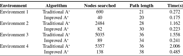
Comparison of search parameters before and after the development of the A* algorithm
Improved A* in case 1. (a) Front view, (b) side view.

The position of the robot arm after the modification is as follows:
 \begin{equation} X_{\delta }=\!\left(x_{0},y_{0},z_{0},\alpha _{0}+\delta \alpha,\beta _{0}+\delta \beta,\gamma _{0}+\delta \gamma \right) \end{equation}
Using the robotic arm’s Jacobi matrix, the relationship between the change in arm pose and the change in joint angle is determined and expressed as:
 \begin{equation} \delta X=J\cdot \delta Q \end{equation}
Consequently, the following equation can be derived:
 \begin{equation} \delta Q=J^{-1}\cdot \delta X \end{equation}
The shortest distance $d_{j}^{X}$
between the robot arm and the obstacle can be solved using the changed joint angle
$d_{j}^{X}$
between the robot arm and the obstacle can be solved using the changed joint angle $Q$
. If
$Q$
. If $d_{j}^{X}\gt 0$
, it is easy to obtain that the robotic arm can avoid the obstacle according to the changed pose. If
$d_{j}^{X}\gt 0$
, it is easy to obtain that the robotic arm can avoid the obstacle according to the changed pose. If $d_{j}^{X}\leq 0$
, it indicates that the obstacle cannot be avoided regardless of the robot arm’s orientation. Since excessive posture adjustment of the robotic arm can result in vibrations and abrupt changes, it is necessary to impose certain limits on the amount of attitude adjustment.
$d_{j}^{X}\leq 0$
, it indicates that the obstacle cannot be avoided regardless of the robot arm’s orientation. Since excessive posture adjustment of the robotic arm can result in vibrations and abrupt changes, it is necessary to impose certain limits on the amount of attitude adjustment.
The constraints are as follows:
 \begin{equation} \!\left\{\begin{array}{l} \!\left| \delta \alpha \right| \leq \varepsilon _{\alpha }\\[5pt] \!\left| \delta \beta \right| \leq \varepsilon _{\beta }\\[5pt] \!\left| \delta \gamma \right| \leq \varepsilon _{\gamma } \end{array}\right. \end{equation}
where $\varepsilon _{\alpha }, \varepsilon _{\beta }$
and
$\varepsilon _{\alpha }, \varepsilon _{\beta }$
and $\varepsilon _{\gamma }$
are the constraint values of posture change respectively. The values of
$\varepsilon _{\gamma }$
are the constraint values of posture change respectively. The values of $\varepsilon _{\alpha }, \varepsilon _{\beta }$
, and
$\varepsilon _{\alpha }, \varepsilon _{\beta }$
, and $\varepsilon _{\gamma }$
are 0.2, 0.2, and 0.1, respectively in the obstacle avoidance algorithm of this study.
$\varepsilon _{\gamma }$
are 0.2, 0.2, and 0.1, respectively in the obstacle avoidance algorithm of this study.
Traditional A* in case 1. (a) Front view, (b) side view.

Improved A* in case 2. (a) Front view, (b) side view.

Traditional A* in case 2. (a) Front view, (b) side view.

Improved A* in case 3. (a) Front view, (b) side view.

Traditional A* in case 3. (a) Front view, (b) side view.

Traditional A* in case 4. (a) Front view, (b) side view.

Traditional A* in case 4. (a) Front view, (b) side view.

4. Experiments and results
Simulation and experimental analysis are conducted in this section to verify the feasibility, effectiveness, and environmental adaptability of the robotic arm path planning algorithm proposed in this paper. The simulation and experimental analysis focus primarily on the search efficiency of the improved A* algorithm, the improved A* algorithm’s adaptability in a multi-obstacle environment, and the practicability of the robotic arm pose adjustment strategy based on the artificial potential field method.
4.1. Simulation and analysis
4.1.1. Comparison of the improved A* algorithm and the traditional A* algorithm
The traditional A* algorithm has many problems in the path planning of 3D environment, including a large number of search nodes, a lengthy search, and a decrease in computational efficiency as the number of obstacles in the environment increases. To verify the benefits of the improved A* algorithm proposed in this paper for path planning, the improved algorithm and the traditional A* algorithm are simulated and analyzed in four map environments, respectively. As illustrated in Figs. 9, 10, 11 and 12. The coordinates of the path’s start and goal points and the parameters of the obstacles in the environment are displayed in Table I. The search step size of the improved A* algorithm is set to 1. The search terminates when the spatial distance between the search node and the goal point is less than 1.
From the simulation results of the four environments listed above, it can be concluded that the improved A* algorithm proposed in this paper can effectively reduce the number of search nodes in path planning when compared to the traditional A* algorithm. Table II displays the search results of the enhanced A* algorithm and the traditional A* algorithm in four environments. It can be observed that the number of search nodes utilized by the enhanced A* algorithm in various environments has decreased considerably. The proportion of search nodes decreased significantly as the number of obstacles in the environment increased, but the final search path length remained essentially the same. Therefore, the enhanced A* algorithm can effectively improve the search efficiency in 3D environment and significantly reduce the defects of the conventional A* algorithm.
Environmental parameter
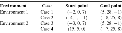
Parameters set for obstacle avoidance environment
Comparing the two algorithms in four distinct situations

Path planning in Case 1. (a) Front view, (b) side view.

Path planning in Case 2. (a) Front view, (b) side view.

4.1.2. Analysis of the environmental adaptability of the enhanced A* algorithm
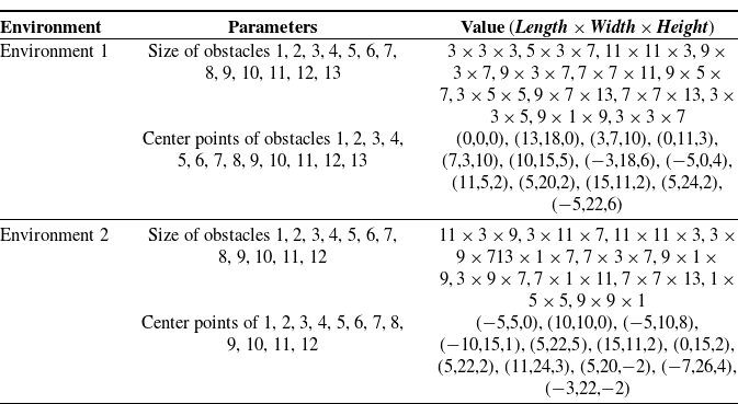
The improved A* algorithm can remedy the traditional A* algorithm’s low search efficiency, but the algorithm’s adaptability to complex environments with multiple obstacles requires further investigation. Two distinct complex environment maps are constructed, and different starting and ending points are chosen for simulation in each map. The outcomes of the simulation are depicted in Figs. 13, 14, 15, 16, 17, 18, 19, and 20. Table III compares the outcomes of the two search algorithms in four distinct instances. The planned routes are displayed from two distinct angles. The beginning and end parameters of the environment-selected path are displayed in Table III. The parameters of the environment obstacles are shown in Table IV, and the improved A* algorithm employs a search step size of 1. The search terminates when the spatial distance between the search node and the goal point is less than 1.
From the simulation results of two distinct complex environments, it is evident that the proposed improved A* algorithm can effectively perform obstacle avoidance planning and that the planned path in a complex environment with numerous obstacles is relatively short. Consequently, the enhanced A* algorithm has enhanced adaptability to complex environments and a degree of generality in path planning. The search time experiences an increase in both the enhanced A* algorithm and the conventional A* algorithm when operating within a complex environment, as opposed to the simpler obstacle avoidance environment previously discussed. Although the simple obstacle avoidance environment exhibits a higher number of nodes and path length compared to the complex environment, the search time in the former remains lower than that in the latter. This phenomenon arises due to the algorithm’s requirement for increased computational time to assess collisions with obstacles and identify viable pathways within intricate environments. Furthermore, the enhanced A* algorithm exhibits significantly reduced search time compared to the conventional A* algorithm, irrespective of the prevailing obstacle environment conditions (Table V).
4.1.3. Simulation of 6-DOF robot arm posture adjustment strategy
The preceding simulation is limited to the path planning of the robotic arm end by the enhanced A* algorithm and does not account for the possibility that the robotic arm’s joint rod will collide with the obstacle. To improve the 6-DOF robotic arm’s overall obstacle avoidance strategy, simulation analysis is performed in the obstacle environment. The simulation is depicted in Figs. 21 and 22, which depict the path planning results of the robot arm with different starting and endpoints. A blue line segment represents the joint rod of the 6-DOF robotic arm, and the environment’s obstacles have been enlarged to be larger than the manipulator’s radius. The parameters of the simulation are presented in Table VI. Following this premise, a total of 1000 starting points and goal points are randomly generated within a space characterized by a radius of 5 units. The coordinates of these points are determined such that the starting point corresponds to the center of the sphere mentioned in Table V, while the goal point corresponds to the center of the sphere as well. The path planning is executed following the proposed overarching obstacle avoidance strategy in two distinct scenarios, and the outcomes are presented in Table VII.
Two simulation conditions

Comparison of the three algorithms in three different cases

Obstacle avoidance algorithm proposed by Jia.

Robotic arm obstacle avoidance experiment.

Obstacle avoidance environment. (a) Path trajectory in Jia’s method, (b) path trajectory in this study.

Comparison of changes in end position. (a) The algorithm proposed in this paper, (b) the algorithm proposed by Jia.

Comparison of end-pose changes. (a) The algorithm proposed in this paper, (b) the algorithm proposed by Jia.

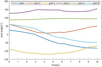
Joint angle changes in the algorithm proposed in this study.

Joint angle changes in the algorithm proposed by Jia.

In the above simulation, both the traditional A* algorithm and the improved A* algorithm proposed in this paper are used for end position obstacle avoidance, achieving a 100% success rate of obstacle avoidance. However, when the posture adjustment method proposed in this paper is used for the overall obstacle avoidance of the robotic arm, there is a slight reduction in the success rate. This decrease primarily stems from the fact that the traditional and improved A* algorithms for end position obstacle avoidance do not consider collisions between the individual links of the robotic arm and the obstacles. However, when the posture adjustment method is employed for the overall obstacle avoidance of the robotic arm, the posture adjustment strategy, based on the artificial potential field, may lead to the local optimum in certain extreme cases. This can, to some extent, reduce the success rate of the search. The path results of the posture adjustment strategy for a 6-DOF robotic arm based on the improved A* algorithm and the artificial potential field method differ from the path results planned by the improved A* algorithm alone, and the path length and cost time have increased significantly. This is due to the posture adjustment strategy determining whether the obstacle collides with the joint rod and adjusting the original path result to accommodate the manipulator’s movement. The attitude adjustment strategy does not guarantee complete obstacle avoidance as the A* and improved A* algorithms do, but its obstacle avoidance success rate is still quite high. It can be seen that the algorithmically planned path has poor smoothness, and jitter may occur in the manipulator’s trajectory motion. Finally, cubic spline processing is applied to the planned path to increase the stability of the manipulator’s motion.
4.2. Experiment in a real environment
To demonstrate the efficacy of the comprehensive obstacle avoidance strategy, an experimental evaluation is conducted to compare the performance of the six-degree-of-freedom joint obstacle avoidance algorithm, which is based on the A* algorithm proposed by Jia [Reference Jia29], with the algorithm proposed in this study. The primary concept of the algorithm presented by Jia involves mapping the search for the position of the robotic arm in 3D space to the search for angles in joint space. The prescribed procedure is outlined as follows: the six joint angles of the robotic arm are designated to be documented as a six-dimensional array. Subsequently, the initial and target positions in three-dimensional space are determined through inverse kinematics, thereby facilitating the computation of the corresponding initial and target joint angles. In Eq. (1), define $G_{i}(q)=\sum\limits_{m=1}^{i}\| q_{i}[6]-q_{i-1}[6]\|$
, and
$G_{i}(q)=\sum\limits_{m=1}^{i}\| q_{i}[6]-q_{i-1}[6]\|$
, and $H_{i}(q)=\max\limits_{m=1,2\cdots 6}| q_{i}[m]-q_{des}[m]|$
. The flowchart of the six-degree-of-freedom obstacle avoidance algorithm proposed by Jia is shown in Fig. 23.
$H_{i}(q)=\max\limits_{m=1,2\cdots 6}| q_{i}[m]-q_{des}[m]|$
. The flowchart of the six-degree-of-freedom obstacle avoidance algorithm proposed by Jia is shown in Fig. 23.
The algorithm proposed in this study is used to conduct experiments on the AUBO-i10 robotic arm, and the arm’s position at multiple points during its movement is recorded, as shown in Fig. 24. Figure 25(a) depicts the trajectory of the algorithm proposed in this study, while Fig. 25(b) depicts the trajectory of the algorithm proposed by Jia. Compared to the obstacle avoidance algorithm proposed by Jia, this study’s algorithm has a significantly shorter path length in real 3D space.
In this simulation, the search time for Jia’s proposed algorithm is 35.386 s, while the search time for this study’s algorithm is. 9.426 s. The primary reason for this is that the proposed method of this study is based on a three-dimensional positional space, and only three spatial positions must be altered during each search. However, Jia’s method is based on six joint spaces, and each search requires changing six joint angles, which significantly increases the search algorithm’s complexity. Under the same motion time, the search trajectories of the two algorithms are compared, and the changes in the end position, end pose, and joint angle are depicted in Figs. 26, 27, 28, and 29, respectively. According to Figs. 26 and 27, it can be determined that, compared to the algorithm proposed by Jia, the algorithm in this study has a smoother position change and posture change of the robotic arm in the three-dimensional space, resulting in less jitter at the end of the robotic arm in the actual motion space. According to Figs. 28 and 29, it can be determined that, compared to the algorithm proposed by Jia, the joint variation range of the algorithm proposed in this study is greater, and the joints in motion exhibit some jitter. This is because the algorithm in this paper searches in the 3D position space and solves the joint angles using inverse kinematics. In conclusion, the algorithm proposed in this study has superior performance in terms of search time, path length, and end position; however, the smoothing of joint angle changes should be enhanced.
5. Conclusion
When operating in three-dimensional environments, 6-DOF robotic arms commonly suffer from the time-consuming computation of obstacle avoidance algorithms, low flexibility of algorithms, and low adaptability to the environment. In this paper, a 6-DOF robotic arm obstacle avoidance path planning algorithm based on the improved A* algorithm and the artificial potential field method is proposed. The proposed improved A* algorithm is used for the path planning of the manipulator’s end, which significantly improves the problems of numerous search nodes and low search efficiency that arise when the traditional A* algorithm is applied to 3D environment path planning. And the enhanced A* algorithm proposes a method for detecting node collisions and local path optimization. Then, based on the improved A* algorithm, a method for adjusting the manipulator’s attitude using the artificial potential field method is proposed to prevent collisions between the robotic arm link and obstacles during movement. Simulation and experiments both validate the algorithm’s practicability as described in the paper.
This paper proposes a 6-DOF robotic arm obstacle avoidance algorithm that is primarily used in static environments where obstacles are known and fixed. Nonetheless, the 6-DOF robotic arm must perform path planning in dynamic scenarios where the obstacles are not fully known. Future research will extend the obstacle avoidance method described in this paper to dynamic environments.
Author contributions
Xianxing Tang established the obstacle avoidance model and designed the path planning algorithm; he also drafted the manuscript. Tianying Xu carried out relevant experiments and data processing, and Haibo Zhou made suggestions and reviewed the manuscript.
Financial support
The authors would like to thank the National Natural Science Foundation of China for its financial support for research project No. 51975590.
Competing interests
All authors disclosed no relevant relationships.
Ethical approval
Not applicable.