


1 Introduction
High-power and high-energy lasers are excellent tools for investigating high-density physics, high-intensity interactions between light and matter and plasma physics. In particular, for inertial confinement fusion (ICF), high-energy lasers are crucial for achieving laser fusion, where the target is compressed by high-energy nanosecond lasers for direct-driven fusion or by X-rays generated by the interaction between high-energy lasers and a hohlraum for indirect-driven fusion[ Reference Haynam, Wegner, Auerbach, Bowers, Dixit, Erbert, Heestand, Henesian, Hermann, Jancaitis, Manes, Marshall, Mehta, Menapace, Moses, Murray, Nostrand, Orth, Patterson, Sacks, Shaw, Spaeth, Sutton, Williams, Widmayer, White, Yang and Van Wonterghem 1 – Reference Li, Chen, Chen, Liu, Gu, Guo, Hua, Huang, Leng, Li, Li, Li, Lin, Lu, Lyu, Ma, Ning, Peng, Wan, Wang, Wang, Wei, Yan, Zhang, Zhao, Zhao, Zhou, Zhou, Zhou, Zhu and Zhu 3 ]. The precision and stability of the laser driver control are critical for the success of ICF experiments at large-scale high-power laser facilities, such as the National Ignition Facility (NIF) in the United States, Laser Mégajoule (LMJ) in France and the Shenguang series in China[ Reference Spaeth, Manes, Kalantar, Miller, Heebner, Bliss, Spec, Parham, Whitman, Wegner, Baisden, Menapace, Bowers, Cohen, Suratwala, Di Nicola, Newton, Adams, Trenholme, Finucane, Bonanno, Rardin, Arnold, Dixit, Erbert, Erlandson, Fair, Feigenbaum, Gourdin, Hawley, Honig, House, Jancaitis, LaFortune, Larson, Le Galloudec, Lindl, MacGowan, Marshall, McCandless, McCracken, Montesanti, Moses, Nostrand, Pryatel, Roberts, Rodriguez, Rowe, Sacks, Salmon, Shaw, Sommer, Stolz, Tietbohl, Widmayer and Zacharias 4 – Reference Zhu, Li, Zhu, Zhu, Ma, Zhou, Lu, Fan, Zhang, Liu, Wang, Yang, Liu, Tang, Sun, Yang, Xie, Zhu, Sun, Liang, Zhang, Ouyang, Zhang, Zhang, Wang, Lin and Fan 6 ]. In the ICF high-power laser driver, in order to reduce the power spectral density and minimize the damage of transverse-stimulated Brillouin scattering (SBS) to large-aperture optical components, as well as the requirement for a uniform focal spot in ICF physics experiments, it is necessary to broaden the spectrum of a single frequency seed source laser, usually using cascaded phase modulation (PM)[ Reference Zhang, Zhou, Jiang, Li, Feng and Lin 7 – Reference Wei, Yuan, Wang, Cui, Yang, Ma, Zhang, Yuan, Zhong, Hua, Li, Zhu, Zhao and Zhang 9 ]. However, due to the nonuniform transmission of lasers, discrete spectra can cause amplitude modulation (AM) on the time–power curve. We call this phenomenon frequency modulation-to-amplitude modulation (FM-to-AM). However, modulation in the time domain can cause damage to optical components and may also affect the effectiveness of ICF physics experiments. Although ICF facilities commonly integrate both nanosecond and picosecond laser systems, FM-to-AM conversion arises only in spectrally broadened nanosecond-class drivers and is absent in picosecond systems.
In principle, pure PM does not affect the temporal intensity profile provided that the spectral transfer function of the optical components is uniform across frequencies. However, in practice, transfer functions are rarely uniform. Consequently, when a broadband laser pulse traverses optical elements, the frequency modulation (FM) is converted into AM, a process known as FM-to-AM conversion[ Reference Hocquet, Bordenave, Goossens, Gouedard, Videau and Penninckx 10 ]. This arises because spectral broadening exposes different frequency components of the pulse to unequal gain, loss or group delay, producing periodic fluctuations in the temporal waveform[ Reference Qiao, Wang, Fan, Li, Jiang, Li, Huang and Lin 11 , Reference Iancu, Talposi, Gheorghiu, Ungureanu, Dancus, Matei and Ursescu 12 ]. The resulting intensity spikes can readily damage large-aperture optics, compromise long-term driver stability and exacerbate laser–plasma instabilities (LPIs)[ Reference Wu, Zhao, Ma, Jiang, Li, Weng, Chen and Sheng 13 , Reference Rothenberg, Browning and Wilcox 14 ]. Thus, FM-to-AM conversion has emerged as a major challenge for high-power ICF laser drivers and remains the focus of extensive studies. At the LMJ facility, the spectral content of the FM-to-AM conversion was analyzed and modeled[ Reference Hocquet, Penninckx, Bordenave, Gouédard and Jaouën 15 ]. At the NIF, a high-throughput diagnostic system was developed to simultaneously identify non-conforming pulses across 48 locations, reducing the measurement time from hours to seconds[ Reference Chou, Valley, Hernandez, Bennett, Pelz, Heebner, Di Nicola, Rever and Bowers 16 ]. Wavelength-conversion techniques have been implemented at the Shenguang II facility to enable remote real-time FM-to-AM monitoring augmented by temporal waveform denoising via deep learning to ensure reliable detection in high-power laser systems[ Reference Huang, Lu, Jiang, Wang, Qiao and Fan 17 , Reference Chen, Lu, Fan and Wang 18 ]. Traditionally, such measurements rely on wavelength conversion, followed by division multiplexing and detection using high-speed oscilloscopes. However, this approach introduces an additional FM-to-AM distortion, and its high cost and system complexity limit its widespread deployment in large-scale laser engineering. Therefore, a compact, modular solution that avoids high-speed oscilloscopes is essential for real-time stability monitoring and cost-effective operation of high-power laser drivers.
This study presents a compact, modular modulation measurement system that eliminates the need for high-speed oscilloscopes, thereby addressing the challenges of cost and complexity associated with conventional FM-to-AM monitoring. The system is centered on a delay-unlocked modulation extractor (DUME) governed by a field-programmable gate array (FPGA). It incorporates an envelope detector (ED) for modulation-depth extraction. Threshold levels are dynamically adapted via an FPGA-implemented dichotomic sliding-window algorithm, enabling robust tracking of dynamic modulation depths. This scalable solution provides a practical foundation for the integrated stability monitoring of next-generation high-power laser drivers for ICF and other large-scale photonic systems. It also provides a solution for detecting the time-domain modulation.
2 Frequency modulation-to-amplitude modulation in inertial confinement fusion high-power laser systems
In ICF high-power laser systems, PM is used to broaden the laser spectrum and produce discrete spectral components. Ideally, PM induces only spectral broadening, while leaving the temporal intensity envelope unchanged. However, in practice, when a spectrally broadened beam propagates through optical components, such as transmission fibers, modulators, amplifiers, isolators, dielectric mirrors and spectral filters, the finite bandwidth and dispersion of these components introduce uneven gain and loss, leading to spectral distortions[ Reference Xu, Wang, Li, Lin, Zhang, Deng, Deng, Huang, Huang, Ding and Tang 19 – Reference Hocquet, Lacroix and Penninckx 21 ]. This spectral nonuniformity drives partial FM-to-AM conversion, which appears as a temporal waveform fluctuation.
Without considering the initial low-frequency temporal shape of the pulse, the optical field can be expressed as follows[ Reference Zhang, Fan, Wang, Wang, Lu, Huang, Xu, Zhang, Sun, Jiao, Zhou and Jiang 22 ]:
 $$\begin{align}{E}_{\mathrm{in}}(t)=\exp \left[i\Delta \phi (t)\right],\end{align}$$
where $\Delta \phi (t)=m\sin \left(2\pi {f}_mt\right)$
is the sine PM,
$\Delta \phi (t)=m\sin \left(2\pi {f}_mt\right)$
is the sine PM, $m$
is the order of the PM and
$m$
is the order of the PM and ${f}_m$
is the frequency of the PM. Its spectrum can then be inferred by expanding the Bessel function after applying the Fourier transform:
${f}_m$
is the frequency of the PM. Its spectrum can then be inferred by expanding the Bessel function after applying the Fourier transform:
 $$\begin{align}{\tilde{E}}_{\mathrm{in}}(f)=\sum \limits_{k=-\infty}^{+\infty }{J}_k(m)\cdot \delta \left(f-k\cdot {f}_m\right),\end{align}$$
where ${J}_k(m)$
is the
${J}_k(m)$
is the $k$
th Bessel function. Equation (2) indicates that the spectrum of the modulated pulse is composed of uniformly separated Dirac peaks. Considering a frequency transfer function
$k$
th Bessel function. Equation (2) indicates that the spectrum of the modulated pulse is composed of uniformly separated Dirac peaks. Considering a frequency transfer function $H(f)$
, the output amplitude can be expressed as follows:
$H(f)$
, the output amplitude can be expressed as follows:
 $$\begin{align}{E}_{\mathrm{out}}(t)={\mathrm{\mathcal{F}}}^{-1}\left[H(f)\cdot \mathrm{\mathcal{F}}\left[{E}_{\mathrm{in}}(t)\right]\right],\end{align}$$
where $\mathrm{\mathcal{F}}$
denotes the Fourier transform. To illustrate the effect of nonuniform transfer functions on temporal waveforms, a phase transfer function similar to a dispersion function is considered in the transmission fiber of the front-end system. The transfer function is expressed as follows:
$\mathrm{\mathcal{F}}$
denotes the Fourier transform. To illustrate the effect of nonuniform transfer functions on temporal waveforms, a phase transfer function similar to a dispersion function is considered in the transmission fiber of the front-end system. The transfer function is expressed as follows:
 $$\begin{align}H(f)=\exp \left(- i\pi \frac{\lambda_0^2 sl}{c}{f}^2\right),\end{align}$$
where $c$
denotes the speed of light in m/s,
$c$
denotes the speed of light in m/s, ${\lambda}_0$
is the wavelength in nm,
${\lambda}_0$
is the wavelength in nm, $s$
is the dispersion coefficient of the optical fiber in
$s$
is the dispersion coefficient of the optical fiber in $\mathrm{ps}/\left(\mathrm{nm}\cdot \mathrm{m}\right)$
and
$\mathrm{ps}/\left(\mathrm{nm}\cdot \mathrm{m}\right)$
and $l$
is the propagation distance of the fiber. A theoretical calculation of the FM-to-AM depth can be found in Ref. [Reference Penninckx, Beck, Gleyze and Videau23], where the optical field at the output of the filter is equal by the following:
$l$
is the propagation distance of the fiber. A theoretical calculation of the FM-to-AM depth can be found in Ref. [Reference Penninckx, Beck, Gleyze and Videau23], where the optical field at the output of the filter is equal by the following:
 $$\begin{align}{I}_{\mathrm{out}}(t)\overset{\cdot }{=}1+\frac{2{\pi \lambda}_0^2{slf^2_m}}{c}\cdot \sin \left(2\pi {f}_mt\right),\end{align}$$
and the FM-to-AM depth is given by the following:
 $$\begin{align}\alpha =\frac{4\pi }{c}\cdot {\lambda_0}^2\cdot s\cdot l\cdot m\cdot {f}_m^2.\end{align}$$
Equation (5) shows that AM occurs at the fundamental frequency of the applied PM and its higher-order harmonics, arising from the nonlinear sinusoidal nature of PM. Therefore, in the following sections, the PM frequency can be detected directly in the time domain. Equation (6) shows that the modulation depth is proportional to both the propagation distance ( $l$
) and FM bandwidth (
$l$
) and FM bandwidth ( $m,{f}_m$
). For a broad-spectrum laser with a large value of
$m,{f}_m$
). For a broad-spectrum laser with a large value of $m$
, an increased propagation distance (
$m$
, an increased propagation distance ( $l$
) can induce significant FM-to-AM conversion. Therefore, it is crucial to measure the modulation near the inspection point. If the laser has no PM, the same analysis would yield an intensity spectrum without AM. To quantify the FM-to-AM, the FM-to-AM depth is defined as follows:
$l$
) can induce significant FM-to-AM conversion. Therefore, it is crucial to measure the modulation near the inspection point. If the laser has no PM, the same analysis would yield an intensity spectrum without AM. To quantify the FM-to-AM, the FM-to-AM depth is defined as follows:
 $$\begin{align}\alpha =2\frac{I_{\mathrm{max}}-{I}_{\mathrm{min}}}{I_{\mathrm{max}}+{I}_{\mathrm{min}}},\end{align}$$
where $\alpha$
is the FM-to-AM depth and
$\alpha$
is the FM-to-AM depth and ${I}_{\mathrm{max}}$
and
${I}_{\mathrm{max}}$
and ${I}_{\mathrm{min}}$
are the maximum and minimum values of the intensity fluctuations caused by the FM-to-AM, respectively.
${I}_{\mathrm{min}}$
are the maximum and minimum values of the intensity fluctuations caused by the FM-to-AM, respectively.
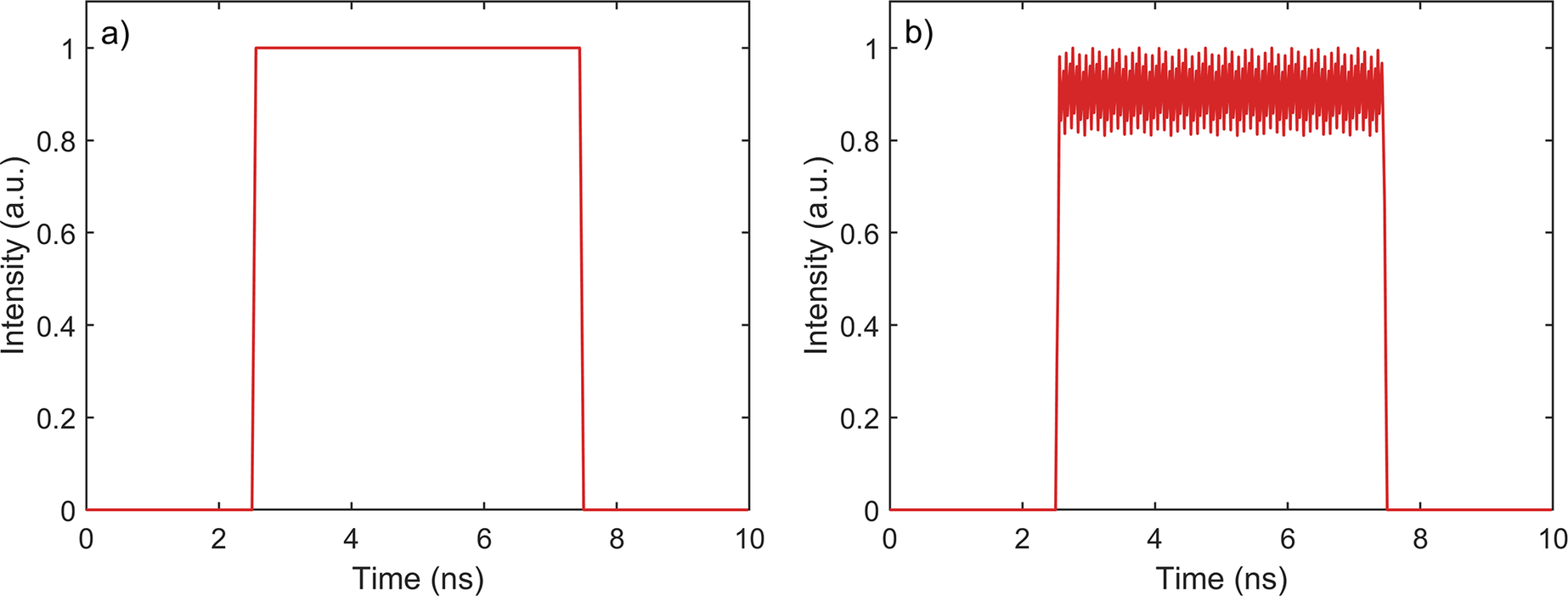
As shown in Figure 1, the FM-to-AM significantly affects the pulse time–power curve, manifesting as pulse contrast enhancement and local intensity spikes, which can easily damage the final optical components and destroy the symmetry of isentropic compression[ Reference Zhan, Yao, Gao, Yang, Zhang and Guo 24 ]. Therefore, it is necessary to introduce high-precision real-time FM-to-AM monitoring technology for the design and operation of high-power ICF laser drivers.
Schematic of FM-to-AM conversion: (a) ideal light waveform without FM-to-AM conversion; (b) laser waveform with FM-to-AM conversion after transmission through an optical element (such as an optical fiber) with dispersion characteristics.

The challenge in FM-to-AM monitoring is the real-time acquisition of high-speed temporal modulation signals superimposed on the pulse envelope. In ICF facilities, the injection laser system is often located far from the diagnostic area and requires both high-speed oscilloscopes and long-distance optical fiber transmission. However, high-speed oscilloscopes are prohibitively expensive and the group velocity dispersion (GVD) introduced by long fibers can induce additional FM-to-AM conversion. Although wavelength-conversion techniques can mitigate this issue, they are expensive and complex.
The phase-modulated unit of the Shenguang II front-end system operates at 3 and 20 GHz frequencies, where the 3 GHz component is mainly used to suppress transverse SBS and the 20 GHz component is used for smoothing by spectral dispersion. To reduce the FM-to-AM conversion caused by polarization mode dispersion, GVD and gain narrowing, several strategies were implemented, including single-polarization transmission fibers, GVD compensation and spectral pre-compensation[ Reference Li, Jiang, Qiao, Huang, Fan, Li and Lin 25 ]. As a result, the FM-to-AM effects in the 3 GHz component were significantly mitigated, with the 20 GHz modulation component being the dominant source of FM-to-AM. In the Shenguang II facility, the FM-to-AM peak modulation depth was suppressed to 18.989% at the position of the beam sampling grating[ Reference Zhang, Fan, Wang, Wang, Lu, Huang, Xu, Zhang, Sun, Jiao, Zhou and Jiang 22 ]. Accordingly, FM-to-AM monitoring focuses on detecting modulation depths of less than 20% at a frequency of 20 GHz.
3 Overcoming rise-time artifacts in frequency modulation-to-amplitude modulation monitoring
3.1 Influence of fast edge pulses on FM-to-AM monitoring
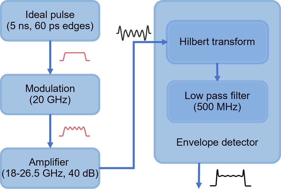
To assess how fast edge pulses distort FM-to-AM monitoring, numerical simulations were performed using parameters that matched those employed later in the experiment.
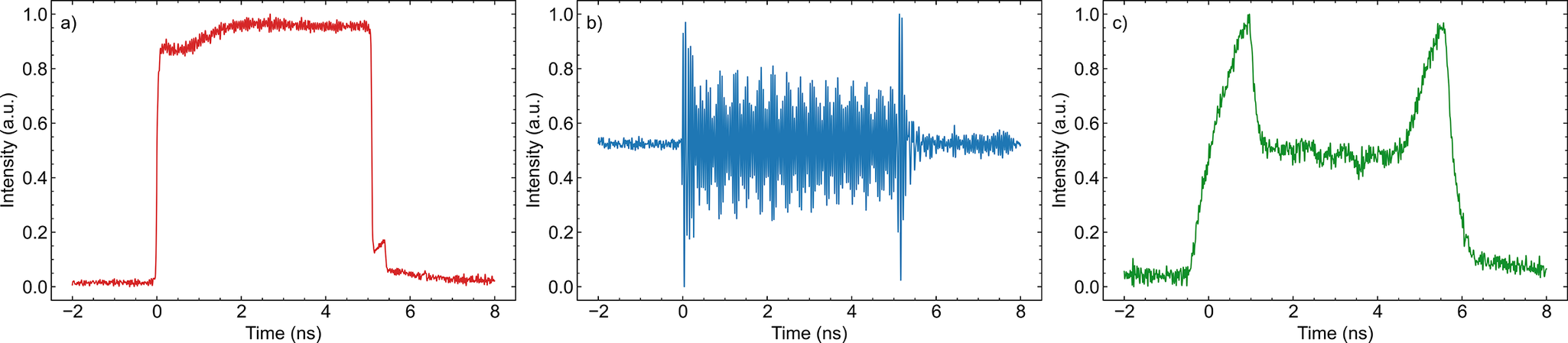
As shown in Figure 2, square pulses with 60 ps rise and fall times were modulated at 20 GHz and passed through a broadband amplifier, followed by envelope detection using a Hilbert transform and low-pass filtering.
Simulation workflow for assessing the influence of fast edge pulses on FM-to-AM monitoring.

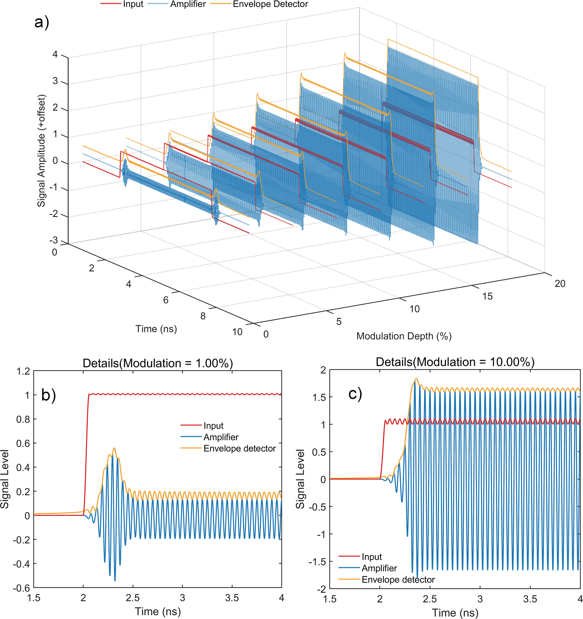
Figure 3(a) reveals a positive correlation between the FM-to-AM and detector output. A higher modulation depth produces a stronger envelope signal. Figure 3(b) shows that the rapidly rising edge of the input pulse introduced transient spikes after amplification. When captured by the ED, these spikes lead to erroneous modulation-depth estimation. Therefore, accurate FM-to-AM measurement requires avoiding such edge-induced transients and extracting the modulation level from the stable plateau region of the pulse following the initial spike. However, Figure 3(c) demonstrates that, while the amplitude of these spikes diminishes with increasing modulation depth, their interference persists. To avoid this issue, a delay-unlocked mechanism was introduced that bypasses the transient spikes in the envelope detection output caused by the rapid rise and fall times of the laser edge pulses. This enhances the accuracy of the module, particularly at low modulation depths.
Simulation results: (a) relationship among signal input, amplifier output and ED output with modulation depth increase; (b) magnified view of the leading edge spikes of the signal input, amplifier output and ED output at a 1% modulation depth; (c) magnified view of the leading edge spikes of the signal input, amplifier output and ED output at a 10% modulation depth.

3.2 System design and implementation
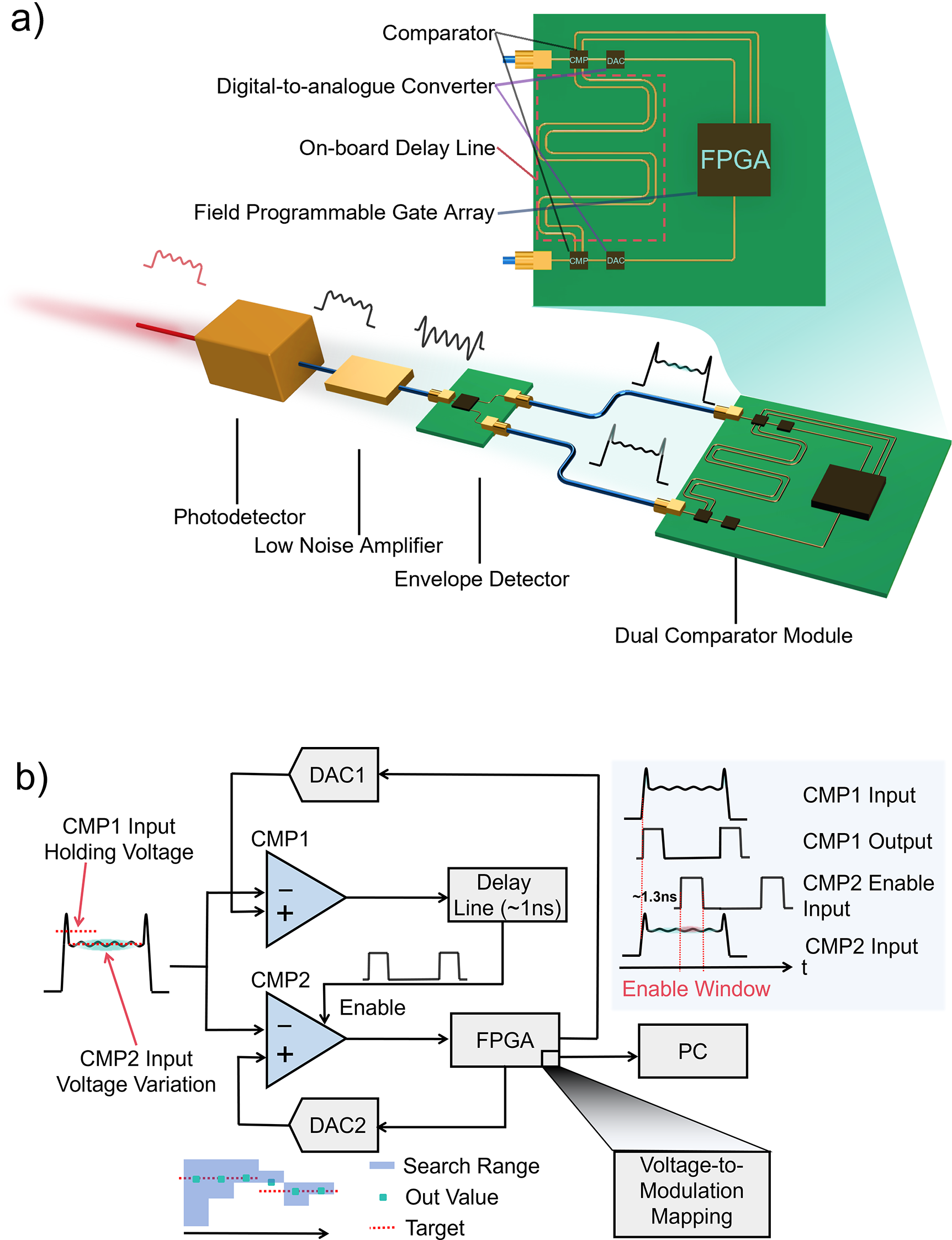
The structure of the DUME, shown in Figure 4, comprises the following components: a high-speed photodetector (PD) that converts modulated laser pulses into radio-frequency electrical signals, a low-noise amplifier (LNA) that provides the necessary gain for radio-frequency electrical signals and an ED that extracts the envelope signal and converts the modulation depth into a voltage magnitude. A dual-comparator structure is used to bypass the rising edge and detect the voltage in the flat region. The FPGA control module drives the digital-to-analog converter (DAC) for threshold scanning, reads the comparator digital signals, calculates the modulation depth and uploads the results. The core principle of the module is to avoid continuous high-speed sampling of high-frequency signals. Instead, an ED maps the temporal modulation depth onto a voltage, which is then digitized using a threshold-scanning comparator to extract the key modulation feature.
Schematic of the DUME: (a) detection module structure diagram; (b) dual-comparator delay-unlocked detection principle and FPGA-based adaptive plateau identification. DAC1, digital-to-analogue converter 1; DAC2, digital-to-analogue converter 2; CMP1, Comparator 1; CMP2, Comparator 2; FPGA, field-programmable gate array.

To overcome detection artifacts caused by the rising-edge spike, the DUME employs a dual-comparator delay-unlocked strategy (Figure 4(b)). These two comparators receive the same detector waveform, but their reference voltages are independently set to perform different functions. Comparator 1, with its reference voltage set between the spike and plateau amplitude levels, triggers the detection of the leading-edge spike and generates a brief enable signal. Comparator 2 is only effective within the peak-to-peak platform, where it performs threshold comparison on the stable part of the envelope.
In order to avoid the influence of high-frequency components in the rising edge on the amplitude FM detection results, the enable path from Comparator 1 to Comparator 2 consists of the intrinsic timing delays of the comparators together with an external 1 ns delay line. The relevant comparator timing parameters include a propagation delay of approximately 150 ps, an enable-establishment time of approximately 90 ps and a hold time of approximately 100 ps. These internal timings contribute approximately 300–350 ps, and when combined with the 1 ns delay line, yield an effective delay of approximately 1.3–1.4 ns. This delay is intentionally designed to exceed the measured spike duration (~1 ns), ensuring that the enable signal for Comparator 2 arrives only after the transient has vanished. As a result, Comparator 2 is active solely within the inter-spike plateau, where it performs a threshold comparison on the stable portion of the envelope; its reference voltage – set by the FPGA-controlled DAC – is updated iteratively to determine the envelope amplitude. This effectively bypasses the influence of transient rising and falling edges, and can accurately capture the true AM signal on the time pulse waveform.
The FPGA receives the narrow output pulse from Comparator 2 on a trigger-configured input, which represents a single, spike-free threshold crossing confined to the plateau region of the envelope. It then dynamically adjusts the reference voltage of Comparator 2 via DAC control, while the reference of Comparator 1 remains fixed. The modulation depth is determined using a dichotomic sliding-window algorithm implemented on the FPGA. Operationally, after each trigger the FPGA compares the current threshold setting with the observed crossing event; if the threshold is exceeded, the upper half of the search window is selected, and if not, the lower half is selected – thereby performing a classical binary split. Once the search window becomes sufficiently narrow, the algorithm switches to a fine-resolution mode that steps the window boundaries inward until the estimated plateau value stabilizes. When the estimated level approaches a window boundary, the FPGA automatically expands the search range to preserve robustness and prevent non-convergence under varying pulse conditions. Once the plateau threshold is identified, the FPGA converts this voltage into the corresponding FM-to-AM depth using a pre-characterized calibration curve and then reports the result to the host computer through a serial interface. By leveraging the time-delay window introduced by the dual-comparator delay-unlocked mechanism, the system achieves stable extraction of 20 GHz FM-to-AM with high accuracy and strong noise immunity, enabling real-time monitoring in high-power laser systems.
4 Experimental verification of frequency modulation-to-amplitude modulation depth testing with the delay-unlocked modulation extractor method
To assess the performance of the FM-to-AM detection module, experiments were conducted using laser pulses with varying modulation depths and temporal profiles. The tests focused on 5 ns pulse durations with various pulse shapes and modulation depths of less than 20% at 20 GHz.
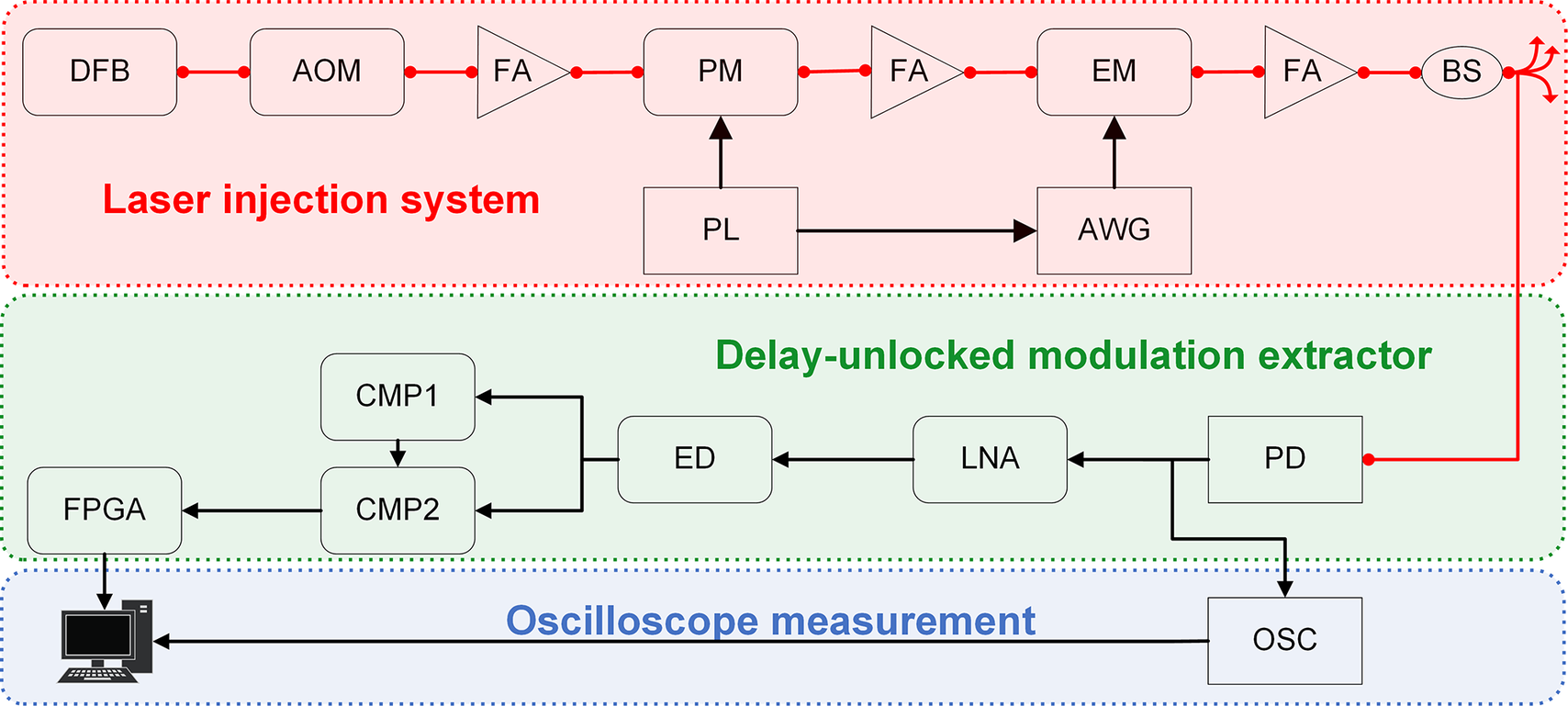
In the FM-to-AM monitoring verification experiment (Figure 5), the laser injection system was initiated by a 1053 nm, single-longitudinal-mode distributed feedback (DFB) fiber laser operating in continuous-wave mode. The DFB source delivered 10 dBm (10 mW) of optical power with a 0.6-nm wavelength tuning range, allowing fine adjustment of the central frequency to match downstream modulation stages. This output was modulated using an acousto-optic modulator (AOM) and subsequently amplified using a fiber amplifier. The AOM provided programmable nanosecond-scale temporal windows (200 ns–1 μs), forming the coarse temporal gate for later high-fidelity shaping. The laser then passed through a two-stage PM system operating at 3 and 20 GHz, respectively, underwent additional amplification and was shaped by an electro-optic modulator for time-domain waveform control. Specifically, the 3-GHz phase modulator broadened the optical linewidth to approximately 0.1 nm for SBS suppression, while the 20-GHz phase modulator further expanded the spectrum to approximately 0.3 nm to meet the beam smoothing requirements of ICF research. High-speed temporal shaping was achieved by driving the electro-optic modulator with an arbitrary waveform generator (AWG). The modulated laser was beam-split and then entered into the DUME module for modulation-depth measurement.
Schematic of the FM-to-AM monitoring scheme verification experiment. DFB, distributed feedback fiber laser; AOM, acousto-optic modulator; FA, fiber amplifier; PM, phase modulator; PL, phase lock loop; EOM, electro-optic modulator; AWG, arbitrary waveform generator; BS, beam splitter; PD, high-speed photodetector; LNA, low-noise amplifier; ED, envelope detector; CMP1, Comparator 1; CMP2, Comparator 2; FPGA, field-programmable gate array; OSC, high-speed oscilloscope.

In order to obtain amplitude FM of different amplitudes, we added a transmission fiber at the monitoring end of the experimental verification to generate amplitude FM signals with different modulation depths. In fact, in the front-end system of the Shenguang II series, due to the use of single-polarization transmission fibers and GVD compensation units, the amplitude FM can be controlled within 5% (2(I max – I min) / (I max + I min)).
The DUME system incorporated an LNA (18–26 GHz, 40 dB gain), an ED (2–67 GHz) and comparators (8 GHz bandwidth). For validation, a high-speed oscilloscope (DSO93004L, 33 GHz bandwidth, 80 GSa/s sampling rate) directly recorded the optical waveform and served as a reference for assessing the accuracy of the FM-to-AM depth extraction module.
Figure 6 shows the outputs of the high-speed PD, LNA and ED with FM-to-AM. These outputs are in excellent agreement with the simulation results, with pronounced spikes at the edges of the amplifier and detector signals. The removal of these transients is essential to prevent measurement errors.
Output of each component: (a) high-speed PD output with FM-to-AM; (b) LNA output; (c) ED output.

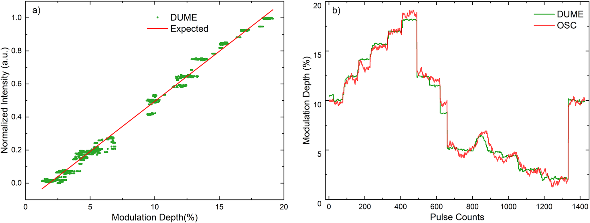
The testing capability of the DUME system for modulation signals was verified by monitoring 5 ns square pulses with a 20 GHz modulation signal and comparing them with the measurement results of a high-speed oscilloscope (DSO93004L). The module accurately resolved the laser modulation depth across the entire tested range (1.27%–19.15%), even under fast-rising-edge conditions, which typically induce significant measurement artifacts.
As shown in Figure 7(a), the correlation between the modulation depths extracted by the DUME module and the oscilloscope benchmark exhibited excellent linearity (R² > 0.99), with the data points clustering tightly around the ideal relationship. This high-fidelity tracking was further evidenced in the time-domain (Figure 7(b)), where the DUME module reliably followed the shot-to-shot dynamics measured by the oscilloscope.
Comparison of modulation depths measured by the DUME module and oscilloscope: (a) DUME measurements (green dots) compared to oscilloscope results (red line); (b) overlay of DUME (green) and oscilloscope (red) measurements across different pulse numbers.

The peak valley deviation of the DUME module relative to the oscilloscope was 2.94% and the root mean square error (RMSE) was 0.48%, which satisfied the strict accuracy requirements of the ICF high-power laser driver for FM-to-AM monitoring.
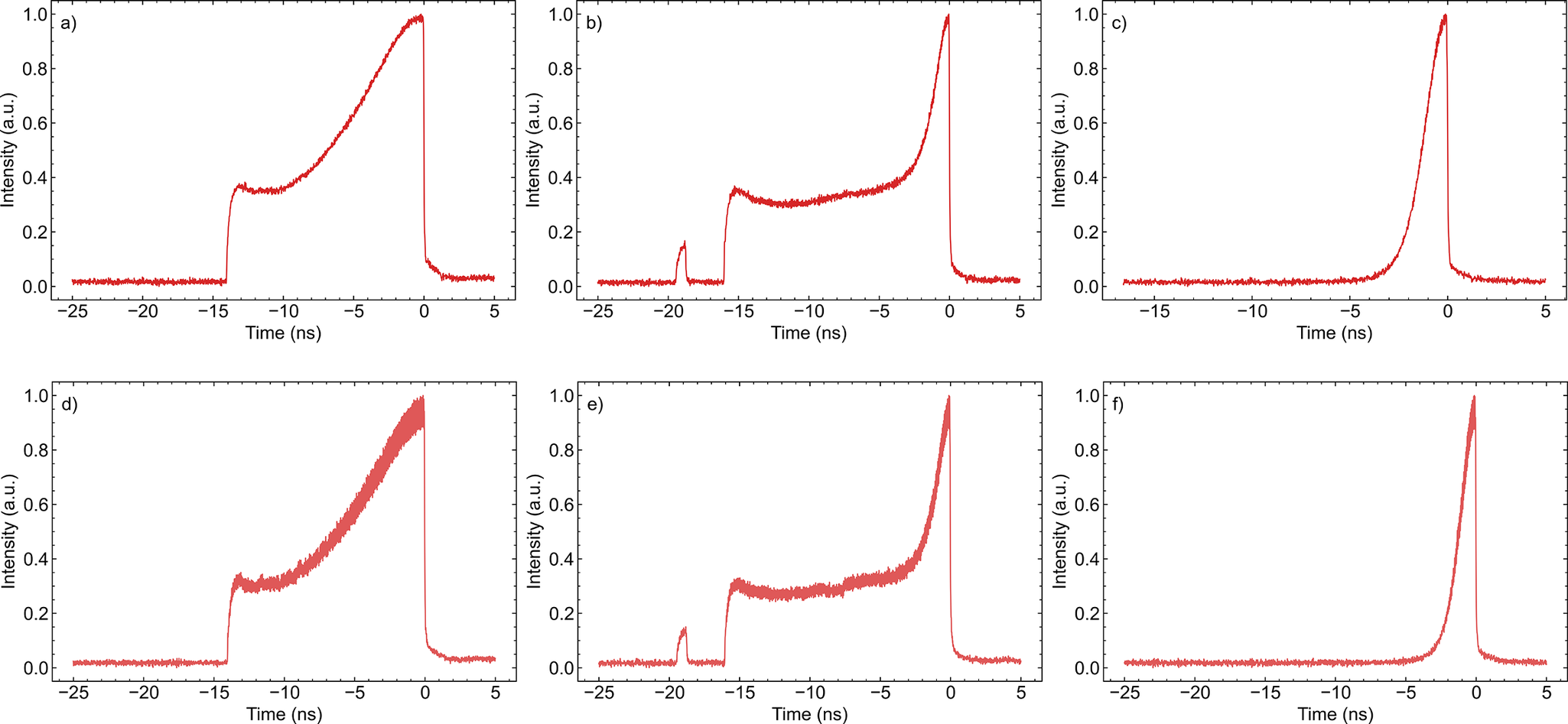
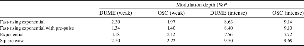
As shown in Figure 8, three typical laser pulse profiles (exponential (Figures 8(c) and 8(f)), fast-rising exponential (Figures 8(a) and 8(d)) and fast-rising exponential with a pre-pulse (Figures 8(b) and 8(e)) were tested using the DUME module.
Laser pulses of different shapes under weak (a)–(c) and intense (d)–(f) FM-to-AM: fast-rising exponential (a), (d), fast-rising exponential with a pre-pulse (b), (e) and exponential (c), (f).

The results listed in Table 1 show that the DUME module can accurately recover the modulation depth under different waveforms. The measured values of both weak modulation (≤2.5%) and stressed modulation (>7.5%) are highly consistent with the measured values of the high-speed oscilloscope, even in the case of pre-pulse or other complex pulses. This consistency highlights the ability of the DUME module to suppress transient artifacts and reliably extract the true modulation depth.
Comparison of modulation depths measured by the DUME module and an oscilloscope with different pulse shapes.

a OSC, oscilloscope.
The experimental results indicate that the DUME time-domain modulation testing scheme is a low-cost and high-precision solution for online real-time monitoring of the FM-to-AM depth in high-power ICF laser drivers.
5 Discussion
5.1 Frequency scalability and detector flexibility of the DUME
A key advantage of the proposed FM-to-AM detection architecture is its modular scalability over a broad modulation frequency range (2–67 GHz). The core delay-locked comparator logic and FPGA-based processing are independent of the modulation frequency provided that the upstream analog front end, particularly the LNA, is selected appropriately for the target frequency range.
The current configuration of the DUME module was optimized for 20 GHz modulation, with an LNA of 18–26.5 GHz bandwidth. For modulation-depth monitoring of other frequencies, such as 3 GHz, it is only necessary to adjust the amplifier in the analog front-end and replace it with an amplifier with a bandwidth that includes the target frequency (e.g., 2–4 GHz). The other components, including the ED and high-speed PD, remained unchanged. Crucially, the dual-comparator hysteresis scheme, DAC adjustment and FPGA-based threshold-scanning logic were fully compatible across these frequency regimes.
For higher modulation frequencies (>45 GHz) and different laser wavelengths, future modifications will involve pairing PDs with amplifiers tailored to the corresponding frequency bands. The current setup utilizes a 1053 nm laser with 20 GHz PM and a 45 GHz PD. In future configurations, PDs optimized for double- or triple-frequency lasers will be employed to monitor the modulation in high-power ICF laser drivers.
This DUME FM-to-AM detection module can be adapted to the time-domain modulation monitoring requirements of various high-power laser systems.
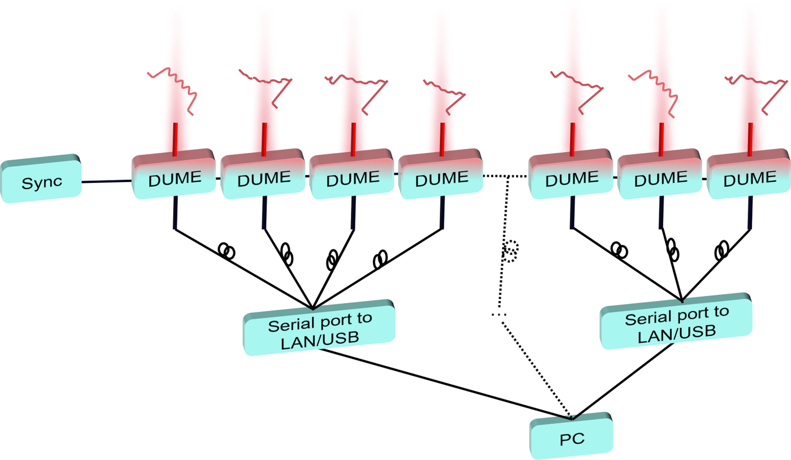
5.2 Multi-channel amplitude-frequency modulation for high-power ICF laser facilities
The DUME module provides rapid and accurate FM-to-AM depth extraction, which is expected to improve the closed-loop feedback control in high-power laser systems. Owing to its low cost, modular architecture and compact footprint, the system allows flexible deployment at arbitrary diagnostic points within a large facility. Furthermore, this module enables real-time synchronized monitoring across multiple channels, thereby forming a scalable network tailored to specific detection requirements.
As shown in Figure 9, the multi-channel monitoring system based on the DUME architecture supports the integration of numerous measurement nodes. Each module outputs a digitized signal that is transmitted via serial communication to the central aggregator through an Ethernet or USB interface. This design facilitates system-wide synchronous data acquisition and high-level analysis, which are critical for maintaining the operational stability of advanced laser systems.
Scalable multi-channel FM-to-AM monitoring system using the DUME architecture.

6 Conclusion
This study experimentally validated a DUME architecture for FM-to-AM detection that eliminates the need for high-speed oscilloscopes. The system reliably measured modulation depths from 1.27% to 19.15%, satisfying the ICF high-power laser facility requirements, whereas saturation was observed at higher modulation levels. It effectively accommodates a range of laser pulse shapes, including exponential, fast-rising exponential and square profiles, and successfully extracts their modulation depths. For the square-wave pulses, the detection errors were PV = 2.94% (peak-to-valley value) and RMSE = 0.48%.
The compact design of the module, low power consumption and scalability make it particularly well-suited for integration into high-power laser systems, providing substantial engineering benefits. Compared with traditional high-speed sampling methods, this approach offers lower costs and enhanced adaptability, making it an ideal solution for real-time monitoring in multi-beam ICF laser platforms. However, the proposed architecture is not designed to extract FM-to-AM depth from a single, non-repetitive pulse, and instead relies on reproducible pulse conditions for stable operation.
Beyond its immediate application in high-power lasers, the detection architecture presented in this study, which is characterized by its compact form, low-cost and digital programmability, serves as a foundational model for integrated modulation analysis. This demonstrates that accurate measurement of key parameters, such as modulation-depth operation at GHz speeds, can be achieved without complex and expensive instrumentation, paving the way for more embedded diagnostic solutions across photonics.
Funding
This work was supported by the Strategic Priority Research Program of the Chinese Academy of Sciences (Grant Nos. XDA25020303 and XDA25020101).

 Open access