


1 Introduction
Due to the prevailing buyer’s market, for continuing success companies are forced to follow the megatrends of globalization and individualization in their products. In many cases, the effort to satisfy the diverse customer requirements results in a product portfolio rich in variants. A large number of variants however lead to an increasing structural and organizational effort for a company. In order to handle this challenge companies try to make the external diversity of products possible with as little internal diversity as possible. For this purpose, standardization methods are applied which are often implemented in conjunction with modular kit systems in the company. Depending on the number of products covered by the portfolio, technically sophisticated and complex systems arise. For the development of such complex systems, either engineers are needed who have intuitively learned to think system-oriented, or methods and tools are required that allow engineers to approach the development processes properly, which are necessary in the development of modular kits. Against this background, the necessity emerges to depict those systems in models. The system models help on the one hand to keep the overview of contained subsystems and their interrelations but on the other hand help to draw conclusions regarding the modeling process itself. In this context the so-called design structure matrices are frequently used (Steward Reference Steward1981).
In the last years the approach of model-based systems engineering (MBSE) has become more and more important in terms of systems modeling. This approach allows to create more complex, interdisciplinary models.
The complexity of modular product families in industry requires modeling approaches that can map several thousand elements and yet are still transparent and reusable, etc. However, the usage of MBSE in modular design in the context of real-world problems has not been the subject of research so far. The aim of the research was to validate the capabilities of the MBSE approach in the modular development of industrial companies to gain a better understanding of how the MBSE approach needs to be further developed to support modular design in an industrial context. Therefore, the authors have conducted several real-world case studies with companies to examine the eligibility of MBSE in the field of modular design. The condensed findings are presented in this paper. To be more precise, the MBSE approach will be used to model complex technical modular kits, and to assist the engineer in this process. In particular it is examined what potentials can be unlocked by means of the methodological support of modular design using MBSE. Furthermore, a modeling framework is derived that provides information from previous product generations to be used to efficiently model modular systems. Finally, this modeling framework is applied in several case studies to support the designing of modular systems in the development practice of modular systems within industrial companies.
In order to examine this in detail, two accompanying studies were carried out in a company over a period of three years. The results can be divided into the following research questions (RQ):
RQ 1. How can a modeling framework that provides information from previous product generations be used to more efficiently model modular systems and products according to the MBSE approach?
RQ 2. How can modular design be supported with the help of the modeling framework according to the MBSE approach?
The studies are based on several years of research by the authors. Individual studies have already been published in previous conference papers and two PhD theses, but have not yet been presented in a coherent manner. In the following, the corresponding publications are also mentioned for the respective studies: chapter 3.1 in (Albers et al. Reference Albers, Matthiesen, Bursac, Moeser, Schmidt, Lüdcke, Maurer and Schulze2014b ) and (Bursac Reference Bursac and Albers2016); chapter 3.2 in (Bursac Reference Bursac and Albers2016); chapter 4.1 in (Albers et al. Reference Albers, Scherer, Bursac and Rachenkova2015b ) and (Bursac Reference Bursac and Albers2016); chapter 4.2 in (Scherer et al. Reference Scherer, Albers and Bursac2017) and (Scherer Reference Scherer and Albers2016); chapter 4.3 in (Scherer Reference Scherer and Albers2016); chapter 4.4 in (Bursac et al. Reference Bursac, Albers and Ölschläger2016a ); chapter 4.5 in (Bursac et al. Reference Bursac, Albers and Schmitt2016b ) and (Bursac Reference Bursac and Albers2016).
2 State of the art
First, the MBSE system-theoretical approach is discussed. In the next step, methods of standardization are defined in the context of system theory. Finally, the modular design is reviewed in detail in the context of product engineering. To this end, particular attention is paid to requirements and knowledge management.
2.1 Model-based systems engineering
The goal of the approach of MBSE is to lead product engineering away from document-centric, heterogeneous product models to consistent and interconnected product models. In the MBSE, the results of different activities of product engineering are to be supported and depicted in a model. These include the activities of the development of a system of objectives, the modeling of principle and embodiment as well as the validation (Walden et al. Reference Walden, Roedler, Forsberg, Hamelin and Shortell2015). In the system modeling the so-called modeling triple, consisting of: language, tool and method, is applied. The language standards specify the elements to be included as well as their syntax. Tools are used to create and manage the models. Methods support the modeling by suggesting a possible approach (Matthiesen et al. Reference Matthiesen, Schmidt and Moeser2015). On the basis of the unified modeling language (UML), the systems modeling language (SysML) was developed in 2007 with the aim of presenting a standard language supported by tools for systems engineering (SE) (Kaffenberger et al. Reference Kaffenberger, Schulze and Weber2012). SysML allows to depict a technical system with its requirements, functions and embodiment elements as well as to reuse parts of existing models. The approach developed in this publication must be suitable to modeling large modular kits with several thousands of mechatronic elements with their requirements, functions and embodiment. Due to the qualitative and descriptive character of the SysML models as well as SysML’s ability to create different views on single modules of the kit on one hand and complete products configured out of these modules on the other hand it was chosen as a tool in this contribution.
To give a short overview of the state of research on the introduction of the MBSE approach in the industrial environment, some current publications are listed below. Amorim et al. have summarized implementation strategies of MBSE for companies based on 10 interviews (Amorim et al. Reference Amorim, Vogelsang, Pudlitz, Gersing and Philipps2019). Cameron and Adsit also developed conclusions about the introduction of MBSE in industrial companies from a large dataset (Cameron & Adsit Reference Cameron and Adsit2018). With a focus on production Kübler et al. accompanied the introduction of MBSE from a research perspective (Kübler et al. Reference Kübler, Scheifele, Scheifele and Riedel2018).
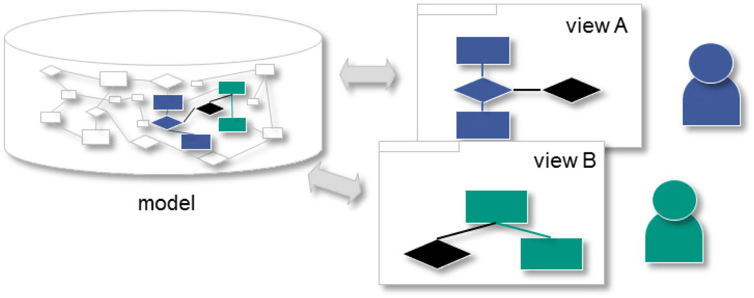
By exchanging views on the basis of mental models of the developers an added value of tool-supported product models is generated (Lamm & Weilkiens Reference Lamm and Weilkiens2014). The used software tools are designed in such a way that the developer is supported in the correct application of the language, for example, by setting only standard-compliant relations. This results in consistent models, which can be projected onto different views. This way, changes in a view cause a change in the entire model. This has the advantage that the model remains consistent and the disadvantage that the modeling itself becomes more complex since only conflict-free changes can be carried out. The distinction between model and view (also referred to as diagram) is shown schematically in Figure 1.
Separation of views and model in MBSE (Alt Reference Alt2012).
Since the languages are very generic, a method supporting the developer is necessary in order to be able to depict different systems using specified language elements (Object Management Group 2011a ). Examples of methods include the object-oriented systems engineering method (OOSE) (Object Management Group 2011b ) or the systems modeling toolbox (SysMod) (Weilkiens Reference Weilkiens2008). Plugins allow the methods to be integrated into tools to match the modeling triple (method, language, and tool).
The modeling language SysML is suitable for the modeling of technical systems and is considered a dialect of the UML (Kaffenberger et al. Reference Kaffenberger, Schulze and Weber2012). The SysML consists of different diagrams (Weilkiens Reference Weilkiens2014): structure diagrams describe the construction and interactions of systems. The functional concept is depicted with behavioral diagrams. The diagrams can be used to map functions, states and interactions between, for example, customers and the technical system. Requirement diagrams have been redefined for the SysML and do not exist in the UML. They can be used to model objectives, requirements and boundary conditions as well as their interactions with the technical system. Numerous studies prove the value added by the system modeling, but they also indicate that it involves a considerable amount of additional expenditure (Albers & Zingel Reference Albers, Zingel, Abramovici and Stark2013), (Bone & Cloutier Reference Bone and Cloutier2010). EHRLENSPIEL & MEERKAMM highlight the need for interdisciplinary integration. At the same time, ‘Whether a “System Modeling Language” (SysML), which necessarily has to be very abstract, is so effective for the joint development of the specialists that it is worthwhile for them to learn the language. It would have to offer advantages regarding quality and time, compared to the current separate creation of plans and programs, which are coordinated from time to time.’ (Ehrlenspiel & Meerkamm Reference Ehrlenspiel and Meerkamm2016). This shows that the approach of SysML has potentials (Friedenthal et al. Reference Friedenthal, Moore and Steiner2014). However, it should be investigated more closely how the abstract language of SysML can be used effectively in product engineering.
The approach of product generation engineering (PGE) (Albers et al. Reference Albers, Bursac and Wintergerst2015a ) extends the findings of conventional methods of embodiment design (Pahl et al. Reference Pahl, Beitz, Feldhusen and Grote2007) and examines the development of products from a new perspective, focusing on the respective parts, which have to be newly developed. According to the naming, PGE assumes that each new product generation is based on an existing reference product (predecessor or competition product), thus a majority of the basic structure is predetermined (Albers et al. Reference Albers, Bursac, Urbanec, Lüdcke, Rachenkova, Krause, Paetzold and Wartzack2014a ).
Thereby, subsystems of the reference product are taken over in the adoption process on the one hand, and newly developed on the other hand. The newly developed parts of the individual subsystems can be categorized into the activity of embodiment variation and principle variation (Albers et al. Reference Albers, Bursac and Wintergerst2015a ). The PGE descriptive model is intended to help to describe more precisely and ultimately optimize product engineering and the associated processes, whereby the model is oriented toward the development practice in companies.
2.2 Methods for modularization and the development of modular kits
This section provides an insight into the state of research on modular design. The most important existing literature and its research focus are briefly summarized and finally a differentiation to the subject of this paper is made. Here the focus is on model-based and system-theoretical support of the development of modular kits.
Ulrich is dedicated to the fundamentals of modularity and formulates a set of research questions to improve the knowledge of modularity in industrial companies (Ulrich Reference Ulrich, Dasu and Eastman1994). He also devotes his research to the effects of product architecture on business processes and the variety of product variants (Ulrich Reference Ulrich1995). The tension between product costs and product individualization in the planning of platform products is also discussed (Robertson & Ulrich Reference Robertson and Ulrich1998).
Erixon points out the key potential of modular design to meet the increased demands and customer needs for high product variance; he points out the increased flexibility by always developing only individual modules of the resulting modular system in order to expand the product range (Ericsson & Erixon Reference Ericsson and Erixon1999). The core of its activities is a method called Modular Function Deployment, which supports the development of modular products starting with customer requirements (Erixon Reference Erixon1998). On the basis of a design structure matrix, Otto and de Weck presented metrics that quantify the functional importance of interfaces and the degree of modularity (Hölttä-Otto & de Weck Reference Hölttä-Otto and de Weck2007a ). They emphasize the tendency that products with demanding package and weight targets tend to oppose an integral design rather than a modular design (Hölttä-Otto & de Weck Reference Hölttä-Otto and de Weck2007b ); thus a completely modular design of building sets is a challenge (Simpson et al. Reference Simpson, Marion, de Weck, Hölttä-Otto, Kokkolaras and Shooter2006).
Stone uses product function models to derive an approach for identifying modules (Stone et al. Reference Stone, Wood and Crawford2000a ) that also takes customer needs into account (Stone et al. Reference Stone, Wood and Crawford2000b ). In this context, a modeling language is introduced that is to define the design space for modeling the shape of the product (Stone & Wood Reference Stone and Wood2000, Hirtz et al. Reference Hirtz, Stone, McAdams, Szykman and Wood2002). Using the Design for Variety approach, Krause presents a development method for modular product families that enables a redesign on the level of functions, operating principles and components (Krause & Eilmus Reference Krause, Eilmus and Birkhofer2011). In particular, non-modular products can be converted into a modular product structure (Eilmus et al. Reference Eilmus, Gebhardt, Rettberg and Krause2012). Strategic aspects and product life phases are also taken into account (Blees et al. Reference Blees, Jonas and Krause2010).
Salvador proposes definitions of modularity that focus on the separability and combinability of components (Salvador Reference Salvador2007). Furthermore, the types and strategies of modularization are analyzed, depending on the product variance and the production quantity (Salvador et al. Reference Salvador, Forza and Rungtusanatham2002). Sosa investigates the influence of the modularity of a product on the cooperation within a development team (Sosa et al. Reference Sosa, Eppinger and Rowles2000), especially in the context of the introduction of a modular product structure (Sosa et al. Reference Sosa, Eppinger and Rowles2004). As a result, interactions between modules are difficult to detect (Sosa et al. Reference Sosa, Eppinger and Rowles2003).
Simpson develops the Product Platform Concept Exploration Method, which can be used to systematically model the relationship between scalable product platforms and the resulting product families (Simpson et al. Reference Simpson, Maier and Mistree2001, Simpson Reference Simpson2004). In this context, we also deal with upstream and downstream topics of platform development, such as term definitions, product positioning and supply chain management (Jiao et al. Reference Jiao, Simpson and Siddique2007).
Lindemann points out that all requirements in the module development must be anticipated and taken into account (Ehrlenspiel et al. Reference Ehrlenspiel, Kiewert and Lindemann1999). This applies in particular to requirements arising from a modular product that is defined much later than the module (Lindemann & Maurer Reference Lindemann, Maurer, Lindemann, Reichwald and Zäh2006). White and Ferguson examine the influence of an architecture on the finished product (White & Ferguson Reference White and Ferguson2017), whereby Kim & Moon and also Greve & Krause address platform strategies for the sustainable reusability of technical systems (Kim & Moon Reference Kim and Moon2017) (Greve & Krause Reference Greve and Krause2018).
Otto et al., who have summarized 13 steps for a modular development from more than 120 publications, present an overview of the research on modular design (Otto et al. Reference Otto, Hölttä-Otto, Simpson, Krause, Ripperda and Moon2016). In more recent publications, the topic of modularization is dealt with in the context of mass customization. André et al. present an industry study on platform design that combines views of both the platform and finished products (André et al. Reference André, Elgh, Johansson and Stolt2017). Pakkanen et al. have identified the most important engineering concepts in this field using the so-called ‘Brownfield Process’ in order to be able to implement modularization and the creation of product families in a mass customization environment: partitioning logic, set of modules, interfaces, architecture and configuration knowledge (Pakkanen et al. Reference Pakkanen, Juuti and Lehtonen2016). The approach is applied on the basis of a case study from industry.
In the field of algorithm-based optimization of modular design kits across several products Sinha et al. have published a paper on the optimal ratio of the maximum degree of modularity with simultaneous minimization of the variation of complexity assignment to the individual modules (Sinha & Suh Reference Sinha and Suh2018). Hou et al. present a method for finding subsystems that can be optimized as modules across multiple products (Hou et al. Reference Hou, Shan, Yu, Hu and Zhang2017). This approach is mainly used in the industrial environment in the concept phase of vehicle design. Publications with a strong industrial reference from the recent past include Shamsuzzoha et al., which have summarized lessons learned on modular development from six industrial partners (Shamsuzzoha et al. Reference Shamsuzzoha, Piya, Al-Kindi and Al-Hinai2018), as well as Mortensen et al., which have identified the following success factors for implementing the module strategy in companies: the company must aim big and be willing to change its foundation accordingly, draw on the right positional strength and have broad organizational inputs, and properly coordinate work and then actively seek to preserve the focus and results over a long period of time (Mortensen et al. Reference Mortensen, Bertram and Lundgaard2018).
Albers et al. (Albers et al. Reference Albers, Scherer, Bursac and Rachenkova2015b ) have evaluated numerous works with regard to term definitions in modular design (selection of evaluated publications: ‘Modular Function Deployment,’ ‘Integration Analysis Of Product Decompositions,’ ‘Towards a Theory of Modular Design,’ etc. (Pimmler & Eppinger Reference Pimmler and Eppinger1994; Stone Reference Stone1997; Erixon Reference Erixon1998; Simpson et al. Reference Simpson, Maier and Mistree2001; Franke et al. Reference Franke, Hesselbach, Huch and Firchau2002; Hölttä-Otto & Otto Reference Hölttä-Otto and Otto2005; Salvador Reference Salvador2007; Lindemann et al. Reference Lindemann, Maurer and Braun2009; Krause & Eilmus Reference Krause, Eilmus and Birkhofer2011). On the basis of these works, they derive definitions of terms that allow the modular design to be considered with the help of system theory. The core of the consistent definitions is the so-called fractal character: At each level of a technical system a different standardization method can be used, e.g. modular construction or platform construction. On the basis of this system-theoretical understanding of modular development, the authors would like to provide concrete methodological support for the modular design with the help of MBSE as a follow-up question, which is dealt with in this publication.
As the strongly summarized overview of the most important research activities on modular development shows, there are numerous approaches to the methodical support of a developer of modular products. However, so far there are no approaches that examine in detail the support of modular development with the MBSE approach on the basis of practical examples. The need for MBSE support for modular kit development arises, among other things, from its complexity, which cannot be completely eliminated by existing methods in the real environment of industrial companies. This complexity and its main origins are analyzed in the next part of this publication.
2.3 Complexity in modular design
When discussing the complexity in the development of modular kits, it must be said there is an important distinction to make between the company’s view and the developer’s view: From the perspective of the company as a whole, the introduction of modular kits can lead to drastic reduction in internal component diversity, which results in the targeted reduction of cost. (It is not for nothing that this is one of the main reasons for introducing the modular principle and is therefore undisputed in this discussion.) For a single developer, on the other hand, the complexity can sometimes increase noticeably. Without modular design, he would have to develop a component that would be used in a few products. With the development of modular kits, however, he now must develop a module that is used in many, sometimes very different products (Figure 2). The above-mentioned technical, scheduling and organizational requirements and boundary conditions for the module and its development are now much more diverse than before, resulting in an increase in the complexity for its developer. The view of the developer is used to further portray the emergence of complexity.
In order to achieve the goal of reduced part diversity (and thus reduced complexity) for the entire company with the aid of modular design, all modules of a modular kit are now used in several products. Hence, the requirements, functions and element of embodiment of a module must suit all of these products, which can significantly differ. This is illustrated in Figure 2 at the example of the automotive industry, in particular with the modular kit development of a hybrid module for a sports car, a SUV and a Sedan.
Complexity in modular design (Scherer Reference Scherer and Albers2016).
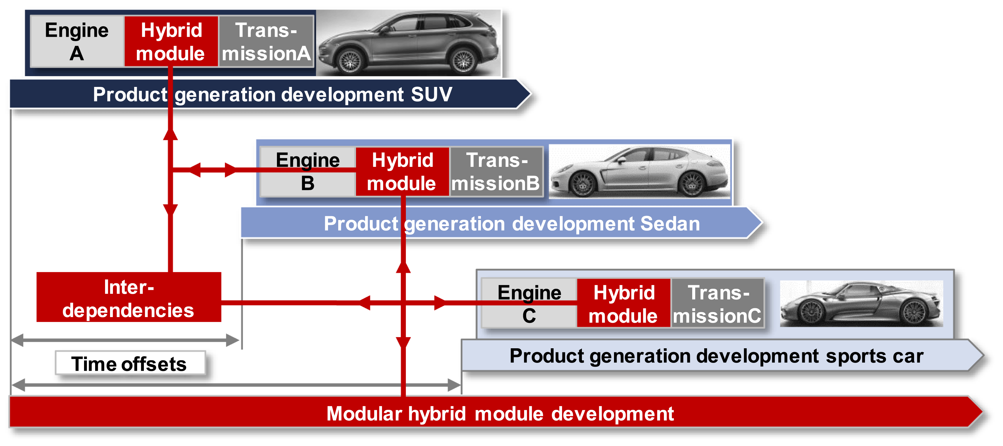
Modular kit development is regarded as a steadily ongoing activity which cannot be completed before the latest product is developed, which uses the module (sports car in this case). This results in large time scopes. Following a definition of Weber (Weber Reference Weber, Samuel and Lewis2005), in which complexity is caused by the number of elements, their interactions and their dynamics, two key challenges for the development of modules which raise complexity can be derived:
(1) Large time offsets:
Because vehicles using the same module are usually not developed simultaneously, but with offset program milestones (Albers et al. Reference Albers, Scherer, Bursac and Rachenkova2015b ) a lot of information, concerning the vehicles which are developed later, is not available at the beginning of module development (see Figure 2). This means the initial system of objectives cannot be entirely completed. The resulting time offsets within modular kit development cause an increased uncertainty regarding the corresponding requirements within the system of objectives of the developed module, since the time span of future projects to be covered by the requirements is extensive and hard to foresee. This leads to a higher overall complexity (Blees Reference Blees2011).
(2) Increased interdependencies:
The initial goal of modular design can be described as the reduction of the in-house variety of components of a company. Due to that circumstance, one could assume modular kits can lower development efforts as well. This perspective misleads to overlook the fact that one module now has to satisfy the objectives, requirements and constraints of several vehicles. As a result of the larger extent, variety and interdependency of the module’s system of objectives, requirements engineering for the module’s development becomes more complex (Renner Reference Renner and Lindemann2007; Scherer Reference Scherer and Albers2016). A higher processual complexity also emerges from the fact, that the increased interdependencies require close collaboration between the vehicle’s developments and the module’s development (Krull & Mattfeld Reference Krull and Mattfeld2012). Accordingly, both the number of requirements elements and the model elements to describe the product architecture of the technical system increases as well. Since the origins of complexity in modular kit development cannot be reduced entirely, methods have to be found that are suitable to cover the large time scopes and highly increased interdependencies. To address the specific challenges that emerge in the course of modular kit development, MBSEs for requirements engineering are investigated.
These two core challenges are particularly prevalent in industries that already have a high degree of product complexity. Since this publication mostly provides illustrative examples from the automotive industry, some characteristics of this sector are given here as examples:
(i) Permanent enhancements and late modifications of the system of objectives as well as a large amount of stakeholders (Heumesser & Houdek Reference Heumesser and Houdek2003).
(ii) Development projects with a customer–supplier relationship in medium to large companies and corporations (Heumesser & Houdek Reference Heumesser and Houdek2003).
(iii) Developers see themselves as product experts, not as requirements management or knowledge management experts (Weber & Weisbrod Reference Weber and Weisbrod2002).
(iv) Dynamic, iterative further development of requirements during development (Almefelt et al. Reference Almefelt, Berglund, Nilsson and Malmqvist2006).
(v) Reusability of requirements is desired and necessary to use synergies and reduce effort (Broy et al. Reference Broy, Feilkas, Herrmannsdörfer, Merenda and Ratiu2010).
The developer’s knowledge of the function–embodiment relation is a success factor in the development of mechanical systems (Hacker Reference Hacker2002). The transfer of the information on the function–embodiment relation thus promotes the development of high-quality technical systems (Wintergerst Reference Wintergerst2015). The C & C2 approach is suited to illustrate transparently these functional structures of complex systems (Albers & Wintergerst Reference Albers, Wintergerst, Blessing and Chakrabarti2013). Furthermore, MBSE approaches exist in order to be able to use the function–embodiment relation in a computer-assisted manner. The modeling language SysML has proved its suitability through the existing methods and especially in the development of mechatronic systems with a high share of electronics and software (Zingel Reference Zingel2013). These methods should be extended to aspects of knowledge management (Scherer Reference Scherer and Albers2016).
3 Framework for modular design
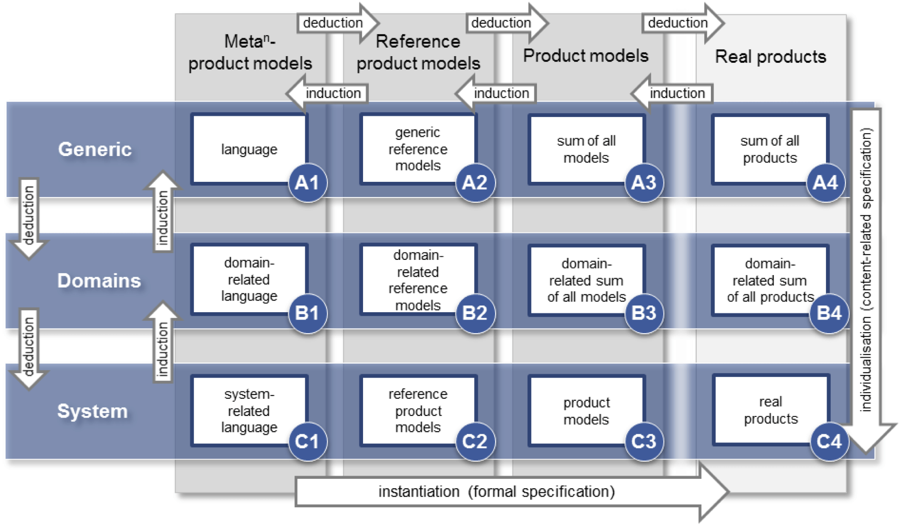
The following section shows how information obtained from the product generations in the context of PGE can help reduce the effort involved in developing product models and thus facilitate the application of the MBSE. It is important to use existing knowledge from previous product generations at an early stage (e.g. for product modeling) and not to start on a ‘blank sheet of paper.’ In order to support this approach expediently, a framework is introduced that demonstrates the different degrees of abstraction from a generic meta-model, to concrete models, to a specific product. For this purpose, an existing framework is further developed, which has previously been used mainly for the illustration of process models (Albers & Muschik Reference Albers, Muschik, Marjanovic, Storga, Pavkovic and Bojcetic2010).
3.1 Product-modeling framework
In a first step, the dimensions of the framework are examined and transferred. To do this, the dimension instantiation is adapted to product modeling. The characteristics of meta-product models, reference product models, product models and real products are selected and explained in more detail below. The characteristics of the individualization dimension (generic, domain, product) are transferred as well. Subsequently, the resulting fields are described in detail.
Based on the Meta Object Facility (OMF) (Object Management Group 2002), the levels meta-model as well as real objects are adopted. The model level is divided into reference product models and product models based on the iPeM (Albers et al. Reference Albers, Reiß, Bursac and Richter2016) in order to show the influence of PGE on the structure of the product. The product models depict the real product. Since meta-models can be described by meta-meta-models, etc., this situation is represented by means of a ‘Metan’ in the product-modeling framework. The introduction of additional meta-levels is dispensed with, since the goal is to create a framework that makes the already abstract meta-models accessible to the development practice by means of PGE. The most abstract level is understood as being generic. Models in this instance should meet the requirements of being able to be transferred to applications of different domains. They should therefore be suitable for an interdisciplinary modeling of technical systems. The classification of the technique in the respective context can be understood as a domain. In the context of the engineering disciplines, electrical engineering, mechanical engineering, etc., or the division into industries: automotive industry or aerospace can be mentioned. Since, so far, no overlapping-free classification of the technology has prevailed, the choice of the corresponding domain in the context of the product modeling is to be selected according to the purpose. On the third level – the system level – the corresponding product, which is to be modeled, can be seen. A product can be a subsystem of another product of the same domain (Bursac Reference Bursac and Albers2016).
Figure 3 shows the product-modeling framework. Twelve fields are derived from the degrees of abstraction of individualization and instantiation, to which various types of modeling of technical systems can be assigned.
Product-modeling framework (Albers et al. Reference Albers, Matthiesen, Bursac, Moeser, Schmidt, Lüdcke, Maurer and Schulze2014b ).
3.2 Support of modular design by the framework
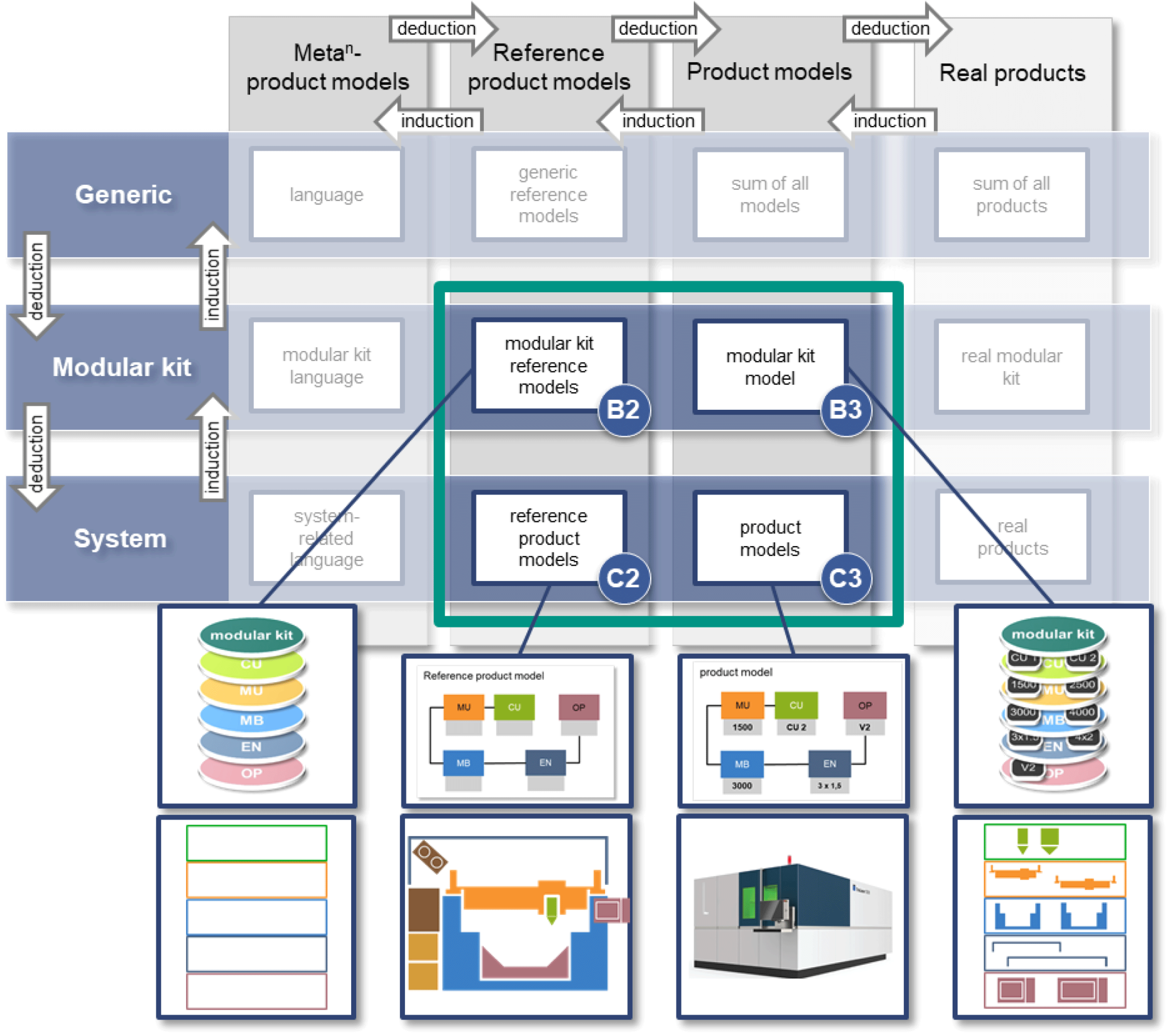
In order to support modular design, the domain is understood as a modular kit. It follows that the individual products can be deductively derived from the modular system and inductively describe the modular kit. This is based on the modular kit reference model, which can be generated inductively from the reference product models. The approach to support modular design can be described using the fields shown in Figure 4. At first the elements of the product-modeling framework and the illustrative example of a machine tool kit for sheet metal processing are discussed in more detail below.
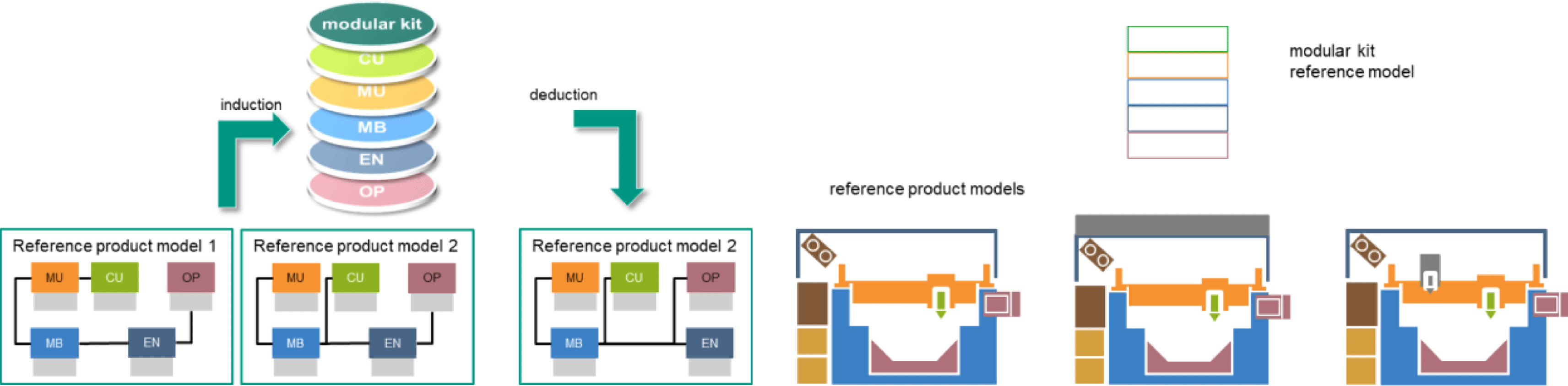
The various components of a machine tool in general can be understood as a meta-model (e.g. Operator panel, Machine Body). The modeled machine tools represent the product models (C3). They have a reference product model (C2) and are based on a modular kit (B3). A uniform color has been chosen to illustrate the relation between the components and reference models. The reference product models (C2) resulting from the reference products describe a knowledge base and can be substantiated specifically for each project.
Elements of modular kit development within the product-modeling framework based on (Bursac Reference Bursac and Albers2016).
On the basis of existing product generations (reference products), information can be illustrated inductively in the reference product model (see Figure 5). These may include further information besides the structure (e.g. item number, weight, cost and installation space) and can deductively be incorporated into the development process.
Correlation of product model and reference product model in relation to a machine tool kit based on (Bursac Reference Bursac and Albers2016).
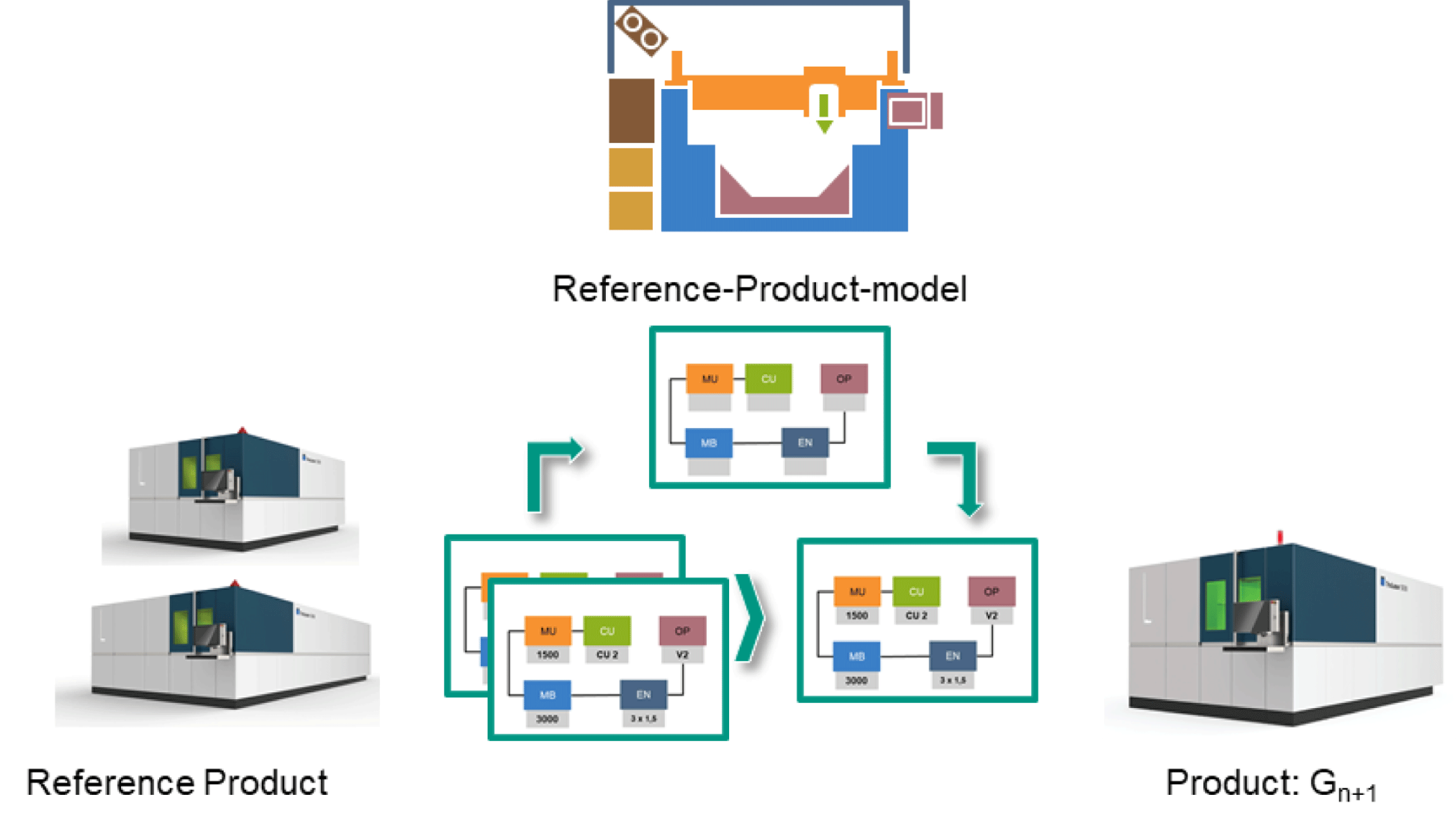
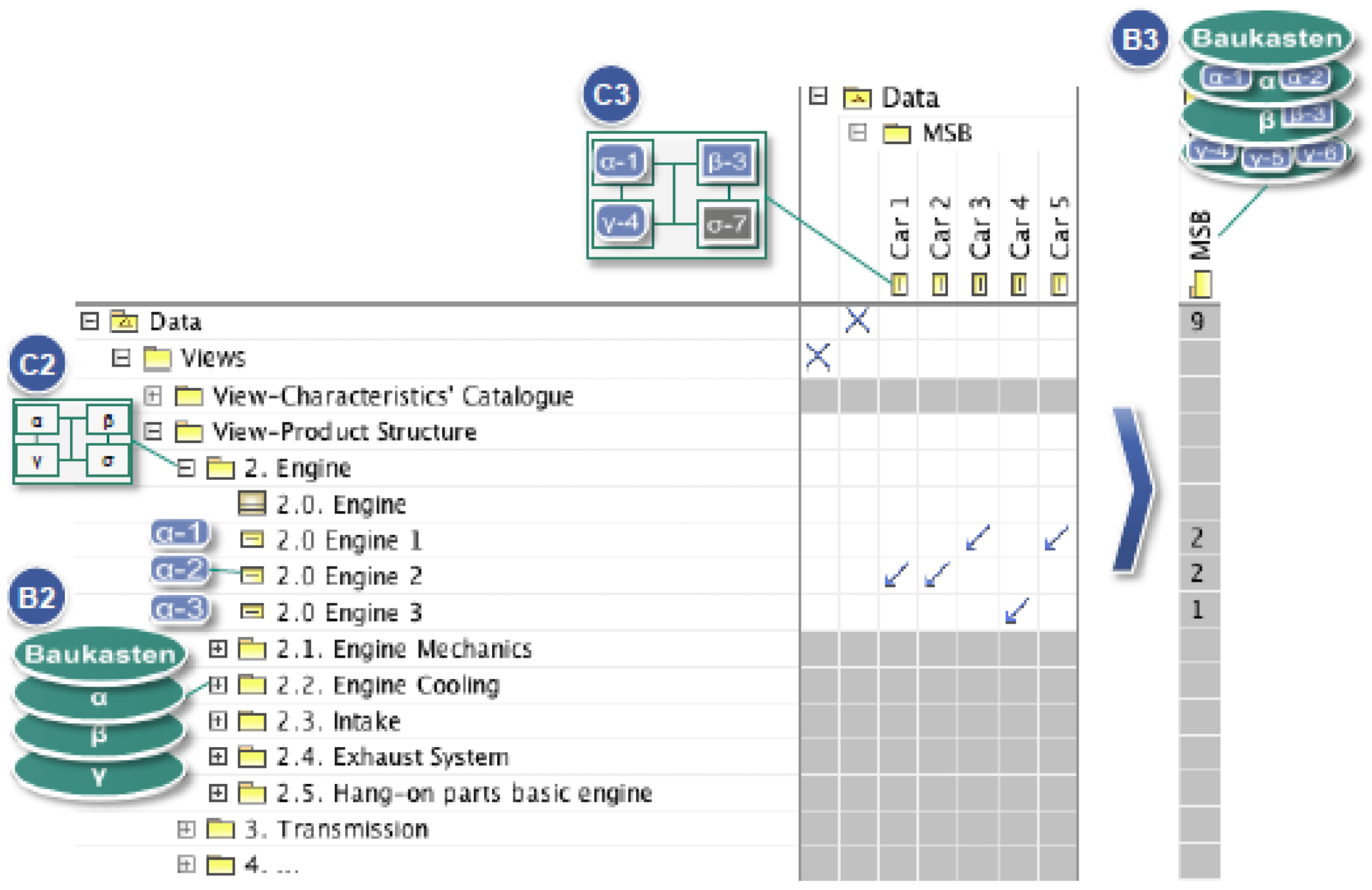
On the basis of the individual reference product models (C2), commonalities can be identified and aggregated into a modular kit reference model (B2). The comparison of the individual reference models shows which parts can be used in a modular kit and which is individual for a product (see Figure 6). This allows to decide on the basis of which products a modular kit can be built and which products might damage the architecture. In addition, it is decided which aspects of the reference model should not be part of the modular design (in the tool kit example the thicker roof top or the additional cutting tool). For example, it is frequently requested that components visible to the customer are not part of the modular kit but are specifically developed for the product in order to be able to individualize the products sufficiently (Bursac Reference Bursac and Albers2016).
Correlation of reference product model and modular kit reference, in general (left) and in a tool kit example (right) based on (Bursac Reference Bursac and Albers2016).
While the reference product model (C2) can be used to model the complete product, the modular kit reference model (B2) is developed for the purpose of interchangeability and comparability of the kit parts. The decisive factor here is that the models are consistent and can be transferred into one another inductively as well as deductively. Otherwise, the information of the products cannot describe the modular kit inductively and simultaneously be used to derive the products from the modular kit. To ensure this, the structures must be based on each other and cannot be randomly determined. Additionally, it is particularly important to consider and adequately describe standardized interfaces within the structure.
If the representation of the reference models is an injective function, it can be explained that a modular kit cannot completely depict a product, but the entirety of the products can completely depict a modular kit. Consequently, it is important to develop the modular kit and the products simultaneously and not the modular kit beforehand. If reference product models (C2) and modular kit reference models (B2) cannot be illustrated, the problem arises that the product models are inherently consistent but inconsistent between the different knowledge management systems (KMSs) which results at best in an insufficient information flow between the corresponding KMSs.
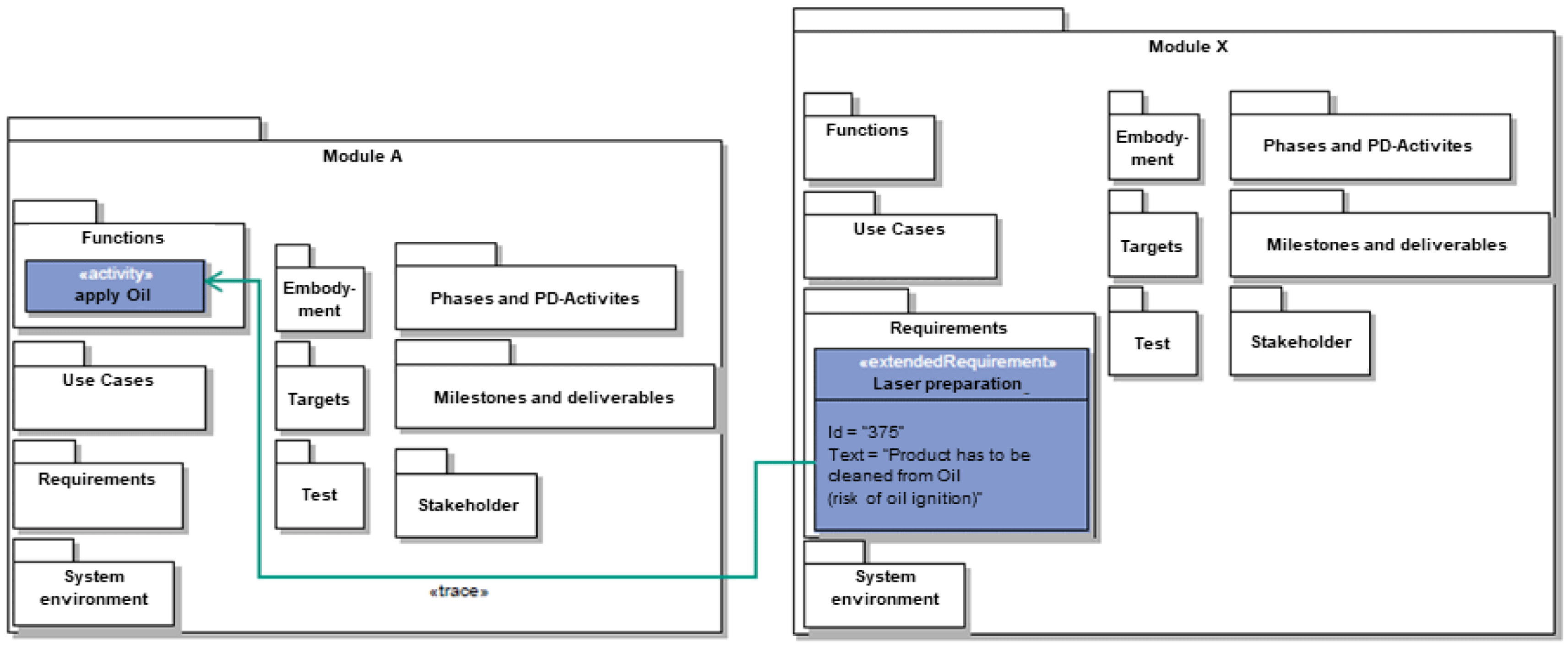
This requires a strict change management, since a change in a model must be repeated at the same time in all models. On the basis of the reference modular kit model (B2), the individual components can be assigned to the modular kit model (B3). In Figure 7, the box and the associated components represent the modular kit model (Bursac Reference Bursac and Albers2016).
Correlation of product model and modular kit model, in general (left) and in a tool kit example (right) based on (Bursac Reference Bursac and Albers2016).
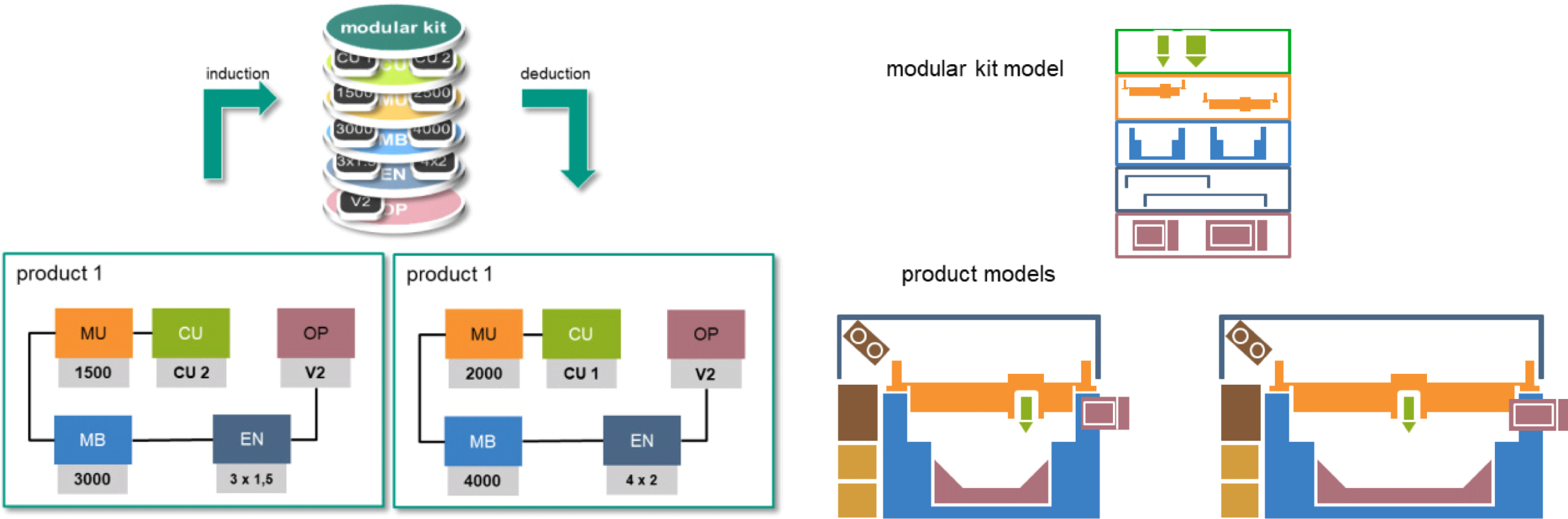
This results in an overview of the existing kit parts. Already modeled components can be reused to efficiently model further products. In addition, the variety of components can be analyzed on one level of the modular kit. This way, for example, it becomes obvious how many different car body styles (blue stones) already exist. This can, in turn, be broken down according to the fractal nature of the methods of standardization. If new subsystems are developed in the context of the development of a new product (e.g. additional cutting tool), it is important not to look at these individually, but also on the basis of this set of rules (regarding interfaces, structure, functions ….) compromised by the modular kit and to delimit it against existing components (see Figure 7). Finally, new product models (C3) can be developed more efficiently using the modular kit models (B3). For this purpose the reference product model (C2) and the modular kit create the basis for the modeling. Therefore, the reference product model (C2) can be understood as a checklist of the early stage and can be defined in a project-specific manner using the modular kit. In addition, there are subsystems, which are not part of the modular kit, such as product-specific differentiation features and newly developed components. The development within the framework of a product always serves as a starting point for new modules and not the development of modules for a modular kit that are later used in products (Bursac Reference Bursac and Albers2016).
As mentioned in the introduction to this section the continuous development of modular kits of technical systems is far more complex as suggested by the basic tool kit example. Besides physical interfaces and structures also electrical and fluidic schematics, software coding, functional descriptions etc. have to be considered. Still the basic principles are the same and the facts and implications apply likewise. Additionally it is important to understand that interdisciplinary modeling is not limited to the modeling of meta-models only but also applies to all modeling levels presented in the framework. However it is essential to model only necessary levels in order to limit the necessary modeling efforts.
4 Case studies from the development practice
Five case studies were conducted to evaluate the framework. They use different fields of the framework. The features and properties of the case studies as well as the fields of the framework used are briefly presented in Table 1.
Overview of case studies
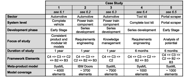
The case studies were carried out by students in the course of their theses. A full-time modeler always developed the models. The system level, the development phase and the focus of study came about through the respective research environment in the industry-related surroundings. In order to ensure both the scientifical and the practical application of the resulting models, the meta-product model was selected to match the already established languages and IT application found in the modular development projects at hand. In the following, the individual case studies and their results are discussed in detail.
4.1 Case study 1: Early stage of automotive industry
The products of most car manufacturers are developed in product generations. This allows for the reference product models (such as the system of objectives, components, functions, and properties), which were identified in early stage analysis, to be transferred to SysML. It is thus possible to create a consistent and linked reference product model (C2 in Figure 4) from the document-centered and independent reference product models in SysML. Figure 8 shows the view of the reference product model on components. Similarly, the view of the system of objectives of the reference product model (C2) can be illustrated, with hierarchically ordered recurring objectives. Thus, for example, the weight can be determined on the first level, and the associated partial objectives, such as the weight distribution on the axles, can be determined on a more detailed level.
Component view of reference product model modeled with SysML: Extract of hierarchical concept of system theory (left) and processed in the structural concept (right) (Albers et al. Reference Albers, Scherer, Bursac and Rachenkova2015b ).
This reference product model is also suitable as a reference model for the modular kit (B2). However, the measure of information is differently detailed at the different levels. For example, in the development of a convertible on the product level, individual components of the immovable roof of the coupé can be irrelevant, whereas, for example, the hybrid module is not used in a conventional drive system. Thus the modular reference model (B2) can be understood as the aggregation of the reference product models (C2). At the same time, the information in the reference product model (C2) can be more specific. For example, the type 911 in the reference product model (C2) can also be used to describe that the engine is located at the rear, while depending on the modular kit in the modular kit reference model, a rear and a mid-engine can be provided (B2). Consequently, the set of rules for the modular kit can be described, using the modular reference model (B2). In this way, it is possible to model at this level for example in which range of weight the products are, which interfaces between the kit parts are necessary or which positions are designated for the engine. Products that do not follow this set of rules may use elements of the modular kit, but are not based on it. In addition, individual elements can be product-specific and not be designated in a modular kit, in order to enable a differentiation of the products. Thus, for example, it is possible to individualize visible components for the customer (Albers et al. Reference Albers, Scherer, Bursac and Rachenkova2015b ).
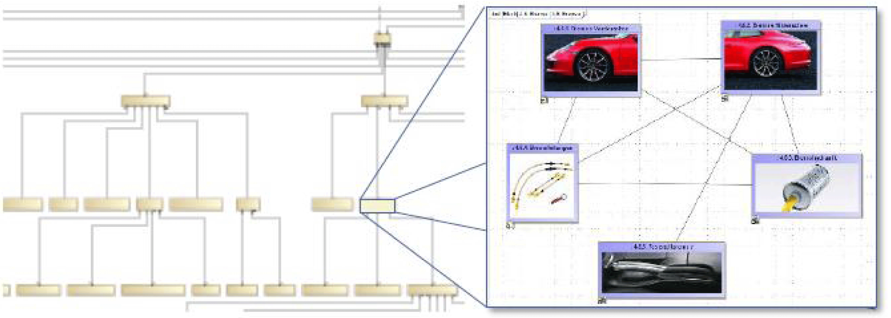
In the SysML model, this is represented by the fact that no relation is introduced between the kit parts and the modular kit model. On the basis of the reference product models (C2) efficient product models (C3) can be created. For this purpose, the characteristics of the reference product model (C2) can be defined. For example, characteristics can be defined for the element ‘engine’ of the reference product model (C2): e.g. ‘V6’ and ‘V8’. These can then be allocated to different products, afterward. A dependency matrix, which is implemented in the SysML tool MagicDraw, is used to illustrate the relations. For the illustration, elements of the reference product model (e.g. engine) as well as the corresponding instances (e.g. ‘V6’ and ‘V8’) are depicted in the rows and the vehicles in columns. Arrows in the matrix represent relations. This makes it clear that a specific engine is used in a specific vehicle. By closing the structure, the number of relations is added up, allowing systematic analyzes. Thus, this example shows how frequently a kit part is used in a modular kit. Figure 9 shows an example of a part of the reference product model (C2) and individual engines as well as the allocation to products (Albers et al. Reference Albers, Scherer, Bursac and Rachenkova2015b ).
View of reference product model, products and modular kit within SysML (Albers et al. Reference Albers, Scherer, Bursac and Rachenkova2015b ).
The dependency matrix enables rapid allocation, which is difficult to achieve with document-centric methods of development. Using the same reference models across product generations allows the method to be used efficiently, since not all contents need to be re-modeled. Furthermore, the networked, consistent modular kit models and product models facilitate a uniform understanding between the project participants, who often belong to different faculties. For example, it is possible to see in which products a module is used or which modules are used in a product. In this way, it is transparent for the module developer in which vehicles a module is being used and for which it is planned. The person responsible for the vehicle is able to illustrate which components are used in the vehicle. The person responsible for the modular kit can use the reference product model to analyze how many variants exist and identify potentials to reduce variants by linking them to the system of objectives (Albers et al. Reference Albers, Scherer, Bursac and Rachenkova2015b ).
This case study has supported the early development stages of a complete vehicle in over a year of modeling and application time by consistent product and modular kit models. Approx. 4000 elements were generated in the model. Five fields of the framework (see Figure 3) could be covered. The study was carried out with the use of SysML (see Table 1).
4.2 Case Study 2: Requirements engineering for series development of modular kits
To address the above-mentioned key challenges of modular design, a new modeling method for modular kit requirements is introduced. As the variety and the extent of requirements of modules is increased the structure has to be capable to deal with that. Figure 10 shows the principles of the developed structure schematically, exemplified by a hybrid module. The radar chart shows examples for requirements that the hybrid module has to satisfy. Each vehicle using the hybrid module can have different values in these requirements, as indicated by the blue lines in the radar chart (e.g. the SUV has the highest wading depth, whereas the sports car longs for the highest peak power figure). This variance in the requirements for the hybrid module must be made obvious by the modeling method for the modular kit, as shown in the dark gray box. Another important specification is the identification of the worst cases (red line), i.e. the technically most demanding value of each requirement. This marking of the worst cases can be the starting point for the efficient validation of each requirement.
Structure of requirements model for modular kits (Scherer et al. Reference Scherer, Albers and Bursac2017).
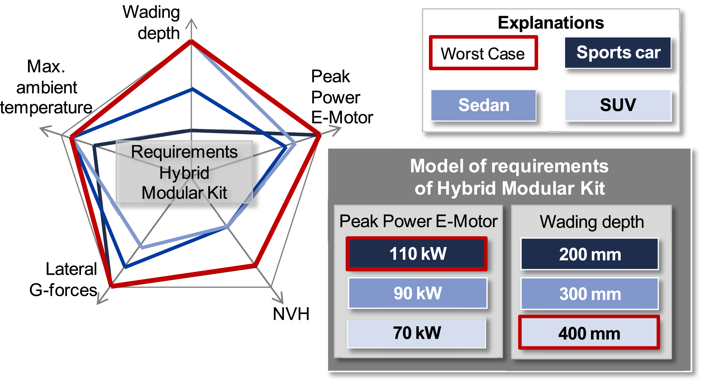
To be able to filter the module’s system of objectives for the different vehicle types (C4 in Figure 3) the relations of multiple values to the corresponding requirements and to the vehicle types have to be taken into account in the process of modeling. As examples, values of electric motor peak power and wading depth vary, dependent on the vehicle types. The advantages using the presented structure are: (1) enabling extensive filtering functionalities, (2) systematically discovering and complementing missing elements, (3) the depiction of the requirement’s ‘worst case’ values. Testing these worst case values first allows to implicitely validate the least challenging values at the same time, which saves time and money regarding the testing process (Scherer et al. Reference Scherer, Albers and Bursac2017).
Following the system theory several element types (e.g. objective, requirement, constraint) and relation types (e.g. expressing hierarchical or competing interrelations) are used to build the system structure. With the help of the relations, stakeholders are enabled to analyze and understand the consequences arising from requirements and their changes in modular design. This can be illustrated with the following example: increasing the value for constant power output of the electric motor requires modification of the requirements regarding cooling. As reusability is one of the basic ideas of modular design, this should also apply to the model elements representing the module’s requirements. Therefore, the presented method can also be used in generic reference models (C2 and B2) and not only in project-specific ones (C3).
The developed method is applied and validated in the series development at an automotive manufacturer where a reference model for systems of objectives (C2) of modular hybrid drive train systems is created. More than seven systems of objectives, including their specification sheets, from former product generations (C3) are applied building the reference model (C2). Based on this reference model several project-specific systems of objectives are derived. To enhance the acceptance of the new method, all modeling approaches were adapted in the requirements engineering tool IBM DOORS which was already in use in the company. Finally, the completed reference model integrated over 3700 objectives, requirements and constraints. Normally DOORS is not considered an MBSE tool. However, it works object-oriented. Consequently, developers can model entities and relations of objectives and requirements, which in the context of this work enables the developed modeling approaches to be mapped in a tool (Scherer et al. Reference Scherer, Albers and Bursac2017).
As mentioned before the reference model (C2) is used to deduce project-specific systems of objectives (C3). Therefore, the reference model was created as a template, which contains all the data necessary for the configuration of the project-specific models. In the course of this, meeting the highest possible share of reusable elements in the deduction process is one of the key challenges. It allows to save time and to carry over the requirements quality standards from the reference model (C2) to the project-specific model (C3). Figure 11 shows the deduction process of project-specific models for different types of modular hybrid systems exemplified by a mild hybrid system, a plug-in hybrid system or an electric axle drive for purely electric vehicles.
Configuration of reference model (C2) and project-specific models (C3) (Scherer et al. Reference Scherer, Albers and Bursac2017).
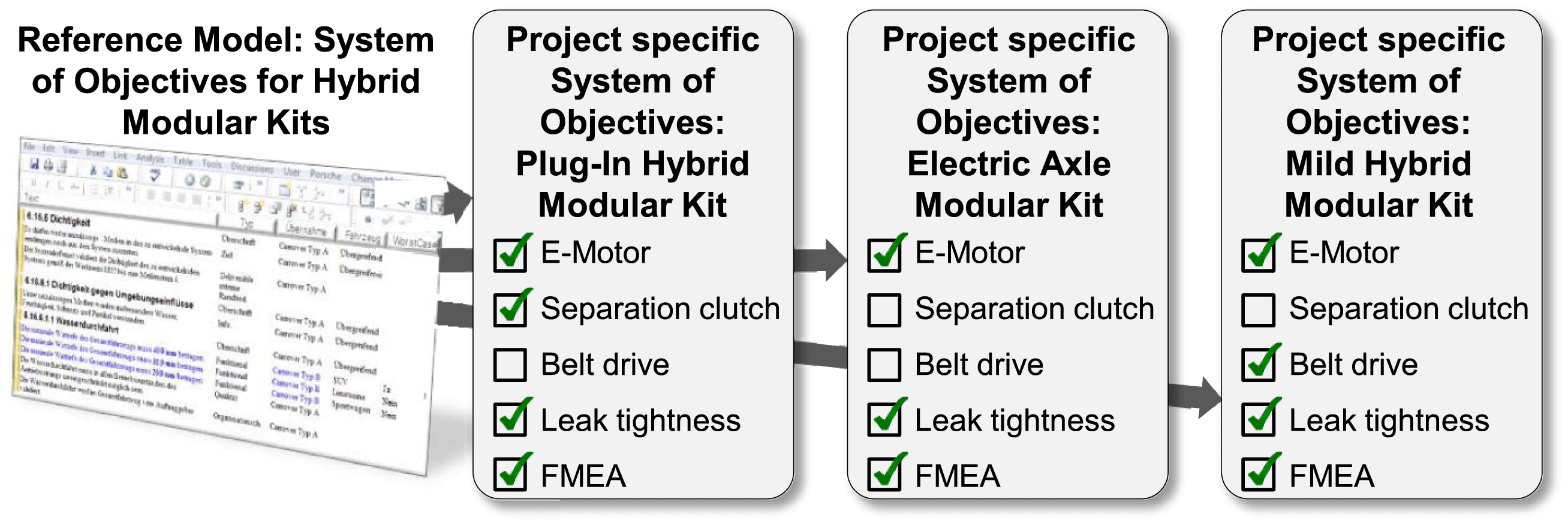
In case of requirements that are mandatory for all types of modular hybrid systems (e.g. electric motor or leak tightness requirements), the DOORS implementation was equipped with attributes that display the relevance of the requirements for one or more hybrid types. Figure 11 shows the results of the investigation on the degree of synergy and reusability in the deduction process of project-specific models out of the reference model for all three types of modular hybrid systems (Scherer et al. Reference Scherer, Albers and Bursac2017).
Reusability of elements of the reference model (Scherer et al. Reference Scherer, Albers and Bursac2017).
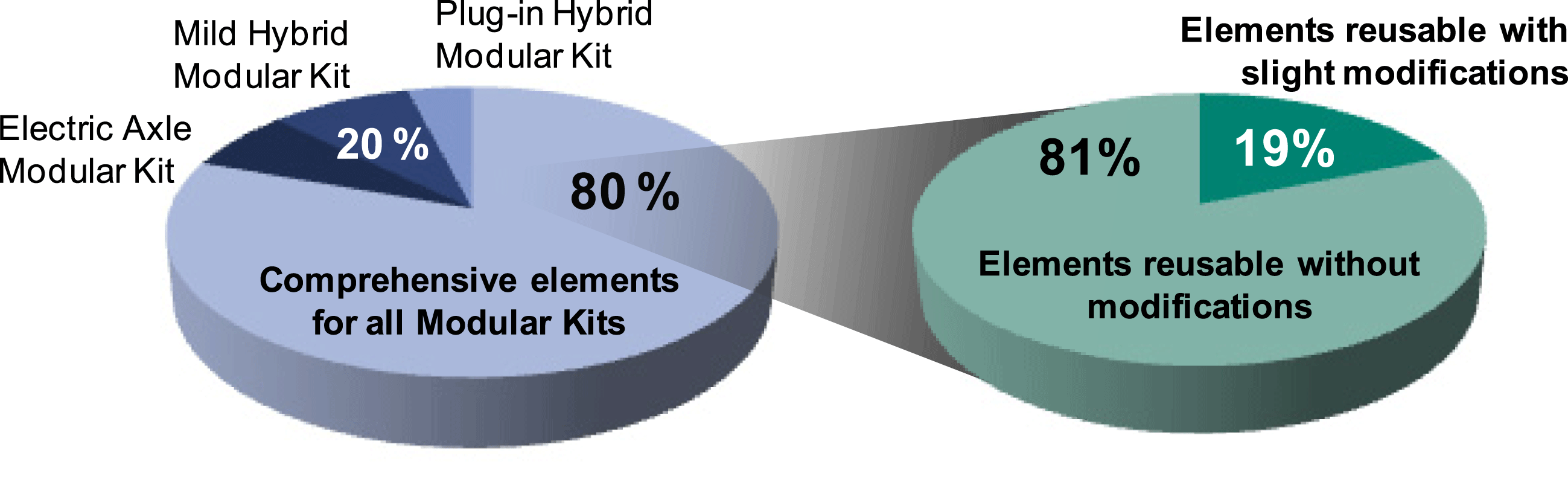
The percentage of the reference model’s elements being relevant for all types of investigated modular hybrid systems is about 80%. All other elements (20%) are specifically used for the mild hybrid type (blue graph). The 80% of comprehensively used objectives, requirements and constraints can be classified into elements that require no modifications at all (81%) and elements that need to be slightly modified (19%; green graph). The necessary modifications include replacing generic place holders of the reference model (C2) with project-specific data (C3), e.g. performance figures, the project’s timeline or an illustration revealing packaging constraints. After performing the modifications, the 19% of elements can also be carried over.
This case study has supported the series development of a modular drive component in over a year of modeling and application time in requirements engineering. Approx. 3700 elements were generated in the model. Five fields of the framework (see Figure 3) could be covered. It is the only study that was carried out in IBM Doors (see Table 1).
4.3 Case study 3: Knowledge management in series development of modular kits
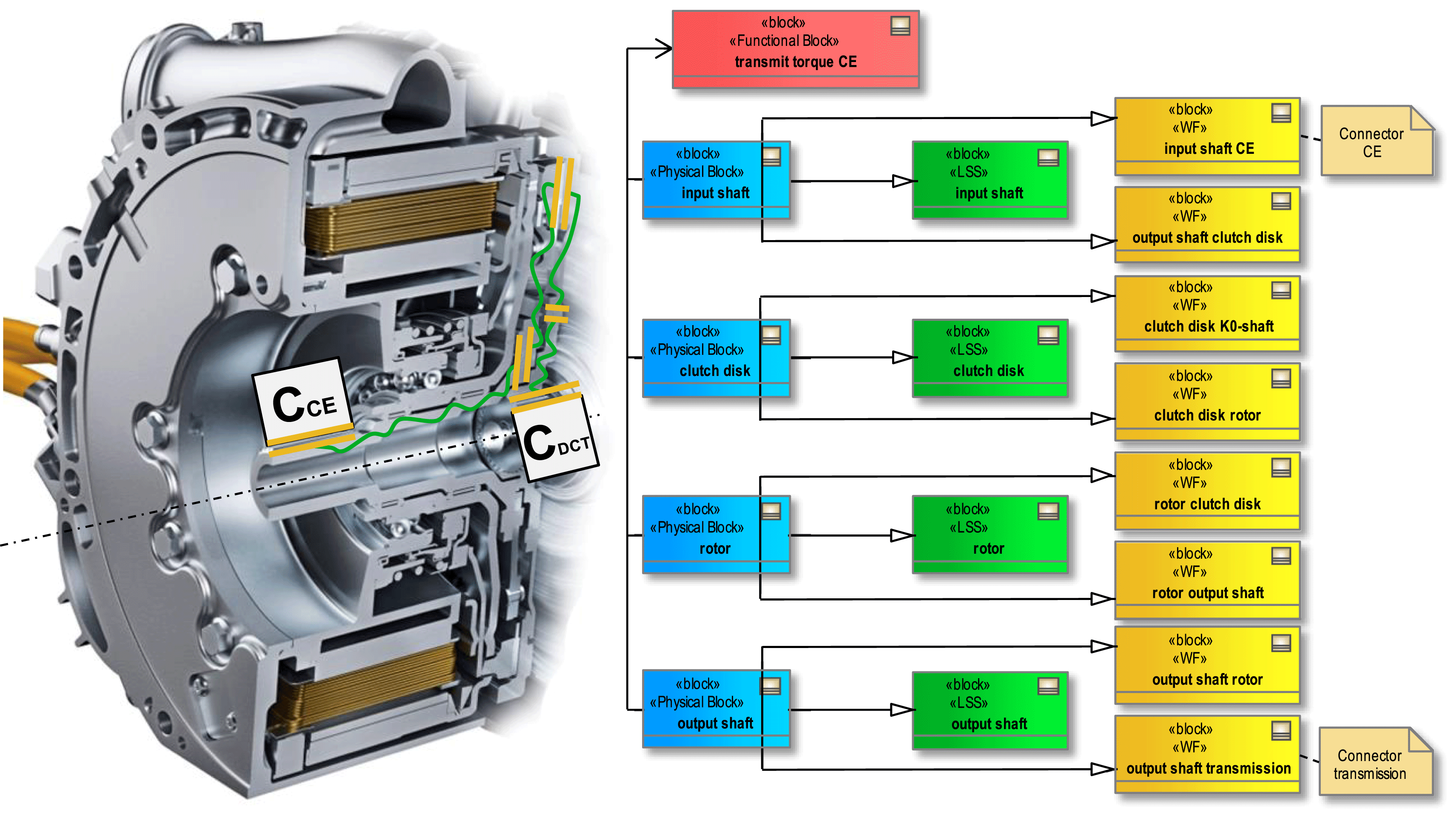
This case study examines whether SysML models of modules can be used to transfer knowledge of the function–embodiment relation in series development of modular kits. In this way, a reference product model (C2) is to be generated from existing product models (C3 in Figure 3). This is intended to create more transparency in modular design. In addition to this benefit, the effort to implement and use the SysML models is also to be quantified. A hybrid module (Figure 13), which is used in a German automotive group for several brands, serves as a case study for the SysML model. The modeling took place in the Cameo System Modeler tool. In modeling technique the C&C2 approach is used (Albers & Wintergerst Reference Albers, Wintergerst, Blessing and Chakrabarti2013). The exemplified operational net of the hybrid module ‘transmit torque CE through the hybrid module,’ consisting of stereotyped blocks of pairs of active operational areas (yellow), conductive support structures (green) and connectors (beige), enables an illustration of components (blue) and their function (red) (Scherer Reference Scherer and Albers2016).
SysML diagram of a hybrid module function (Scherer Reference Scherer and Albers2016), (Richter et al. Reference Richter, Schiek, Stache, Spiegel and Kerner2013).
With this modeling technique, a system model (C3) of the hybrid module was created that contains all the main functions and components including their functional structure. It can now be used to store information, lessons learned and best practices on the function–embodiment relation of a module generation in the reference product model (C2) and to provide it for the development of new product generations. In the SysML model, it is possible to record the features and properties of components that a developer can use to access the acquired knowledge. The attributes can be used, in particular, if lessons learned have been developed for components or if details for the following module generations are to be documented. Over a period of one year, 31 lessons learned from four years of hybrid modular design were integrated into the reference product model (C2). Here are some examples for these lessons learned with varying complexity and thus varying modeling effort:
(i) Less complex: change of materials and of hardening process due to plastic deformation of the input shaft of the hybrid module.
(ii) Medium complex: optimizations at the point of contact between the clutch actuator & diaphragm spring.
(iii) Complex: Multi-parameter optimization of the heat transfer from the stator of the electric motor into the cooling water jacket.
The knowledge gained through solving development problems could previously not be accessed at any central location in the company and was not available for further developments of modular kits. Now however, knowledge necessary to solve development problems of the past is made available by the SysML model to all project participants (Scherer Reference Scherer and Albers2016).
This benefit of the SysML model was evaluated in a survey of development engineers. For this, the subjects were presented with modeled lessons learned, which they had not previously known. Afterward, they used the criteria shown in Figure 14 to assess the added value of the SysML model:
(i) Is the representation of lessons learned comprehensible in the SysML model?
(ii) Is the operation and navigation within the model reproducible?
(iii) Has the analysis of the SysML model improved the understanding of the system of the hybrid module, and did a knowledge transfer occur?
Benefit of SysML model: Results of developer interviews (Scherer Reference Scherer and Albers2016).
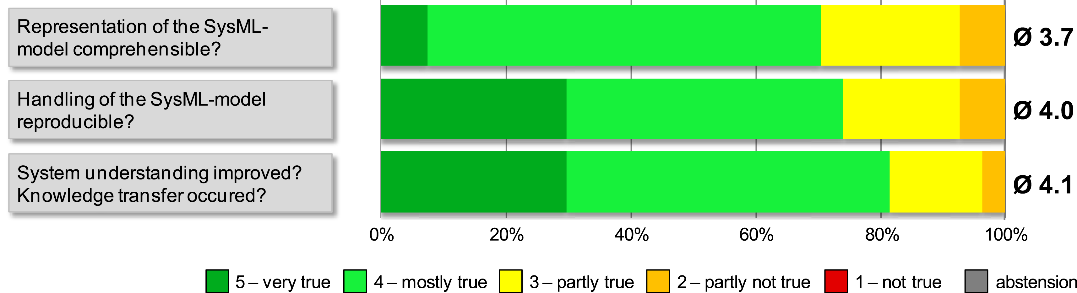
On the basis of the average score points of 3.7 to 4.1 from 5 points available it can be stated that the evaluation was positive. As a result, a reference product model (C2) is now available for the development of the following product generations. The modeler documented the effort to create and maintain the SysML model based on the occurred modeling time for each lesson learned. This resulted in different processing times due to the different scope and complexity of the processed cases. The average processing time is 2.7 hours. Regarding the complexity of the lessons learned the processing time appears to be relatively long. For a detailed reflection, four proportions of the modeling time are formed (Figure 15) and possibilities for improvement are discussed (Scherer Reference Scherer and Albers2016).
Proportions of modeling times of lessons learned (Scherer Reference Scherer and Albers2016).
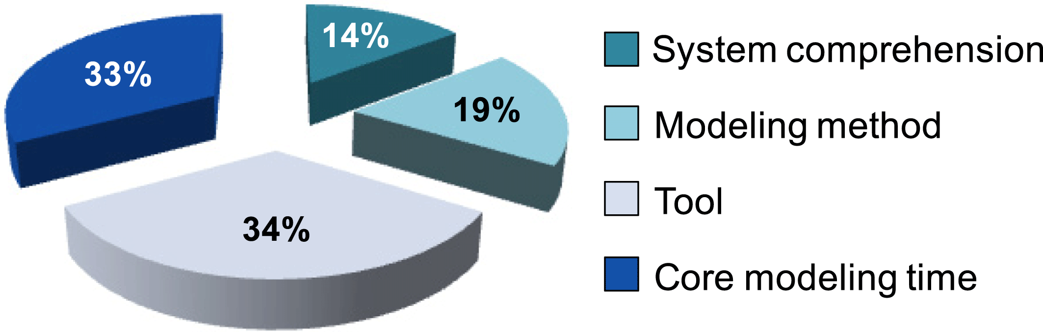
(i) System comprehension: Model developer acquires knowledge of the lessons learned. In this step, it was often necessary to switch between the 3D CAD system of the hybrid module and the SysML model because it was possible only in the CAD to analyze sound 3D views. This permanent switching between tools took time, which could be saved in a computer-assisted coupling of CAD and SysML.
(ii) Modeling method: This part contains the transformation of the lesson learned into the modeling method, which is the mental preparation for the illustration of the operational net in the SysML model.
(iii) Tool: This is the largest part and includes the operation and the understanding of the modeling tool. With increasing model size, especially extending 5000 elements, the tool became increasingly unstable, it crashed more frequently, hyperlinks were destroyed and had to be re-created. This took time and results from the degree of maturity of the tool.
(iv) Core modeling time: This part involves synthesizing the lesson learned into the existing SysML model.
This case study has supported the series development of a modular drive component in over a year of modeling and application time in knowledge management. Approx. 7000 elements were generated in the model. Three fields of the framework (see Figure 3) could be covered. The study was carried out with the use of SysML (see Table 1).
4.4 Transfer study 1: Development of an Industry 4.0 production machine
The starting point of the methodology is the depiction of product variants (C4 in Figure 3) in virtual product models (C3). The information and knowledge of the modular production machines merge in a central SysML model by the creation of diagrams (see Figure 16) and are thus documented for various specialist areas.
Example of development goals of a new product generation (Bursac et al. Reference Bursac, Albers and Ölschläger2016a ).
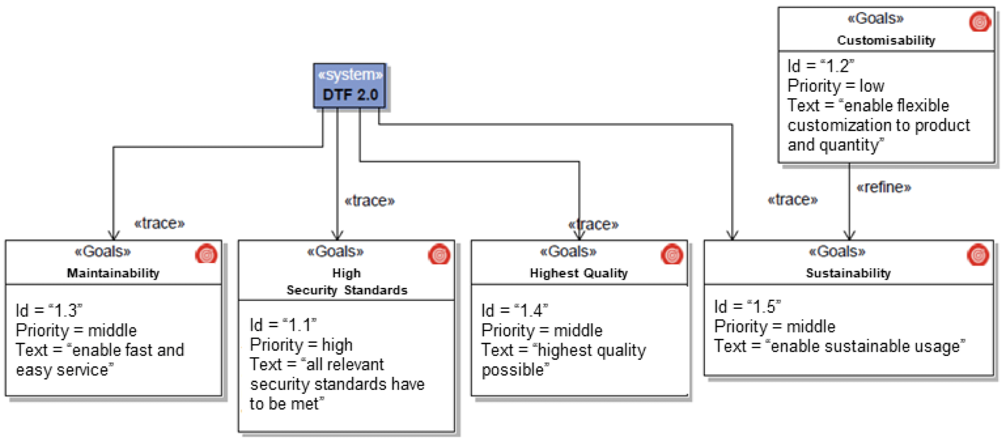
Figure 17 shows a SysML requirement diagram of the partial model ‘Goals.’ The illustration shows the actual purpose of the system to be developed. Requirements can now be assigned to the objectives, and functions or embodiment of the product can be derived from the requirements. Although the architecture of the machine concept is not bound to a fixed structure, a way must be found to generate a reference model. For this purpose, the system of objectives as well as the partial model’s stakeholders, requirements, applications, functions and embodiment and system environment were modeled. The elements of different subsystems could be linked together, with the aid of the depiction, in a hierarchically structured packet diagram (see Figure 17) (Bursac et al. Reference Bursac, Albers and Ölschläger2016a ).
Example of networking of model elements (Bursac et al. Reference Bursac, Albers and Ölschläger2016a ).
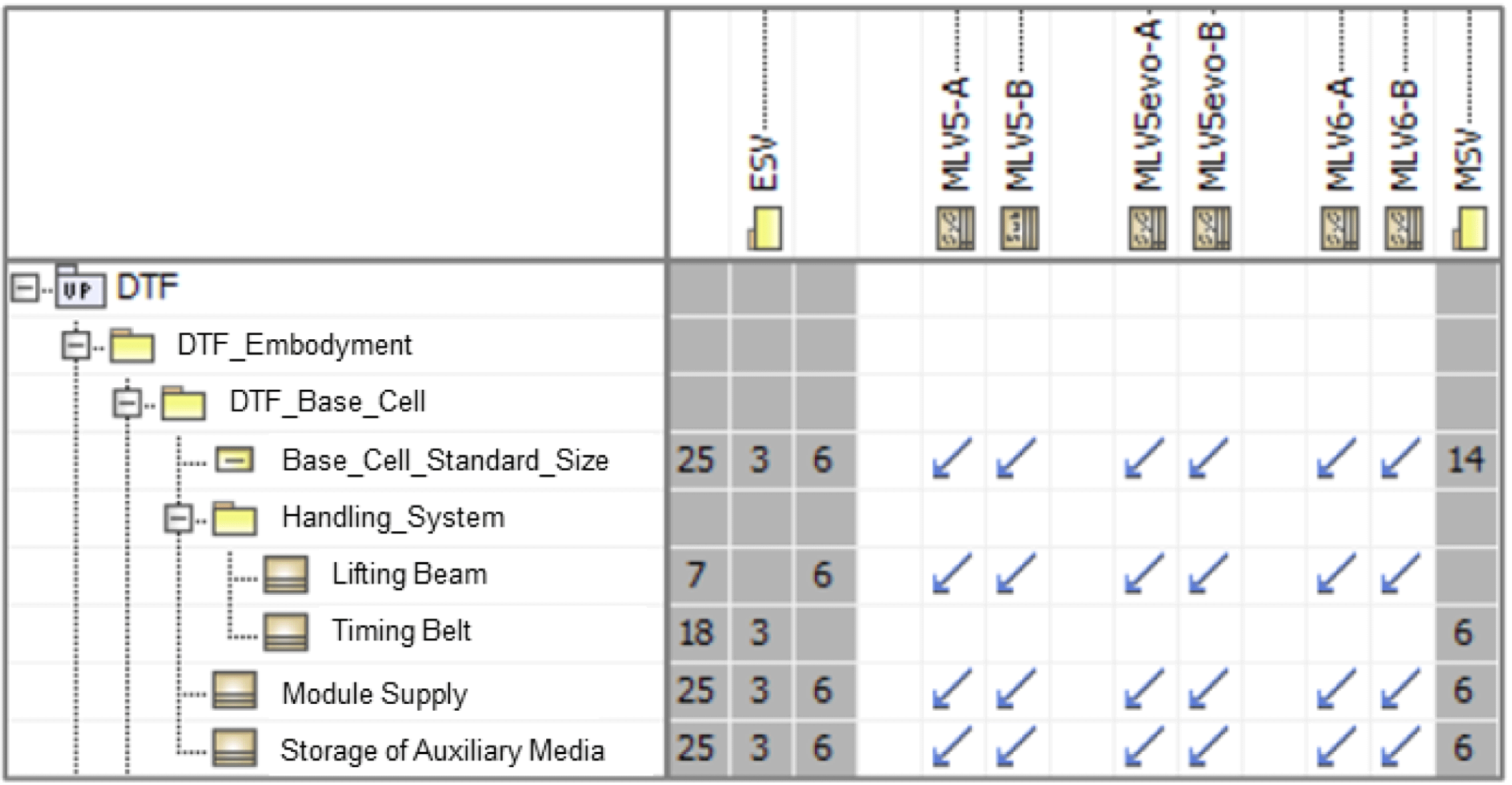
In the second step of the process, reference models (C2 in Figure 3) are generated. These form, by means of an abstract description, several variants of a product family (C3) and thus serve as a knowledge base according to PGE. Through hierarchical structuring of the systems of objectives, the elements of the subsystems can be distributed to the partial models of the subsystems. Thus, requirements with different characteristics can be distributed to the systems of objectives of the associated subsystems. As a result, reference models can be generated relatively easy, despite the free module configuration. The product architecture was classified and structured by appropriate methods of standardization. It was observed that the architecture of the systems of objectives and of the products iteratively assimilated. In a third step, the reference product models (C2) of the product families are now layered to a common modular kit reference model of all product variants. The template for the modular kit therefore defines which elements can be arranged within the modular kit. From an economic point of view, it is important to maximize the variety of product variants and to minimize the variety of subsystems, for the configuration of products. By linking the model contents of the partial models, conflicts between the elements can now be revealed and graphically documented. The template for the modular kit thus provides a set of rules with which the modular kits can be modeled consistently. Step 4 of the process model is an instantiation of the reference model of the modular kit (B2) by specification of the elements of the model. A matrix, that illustrates which subsystems are used in which product variant (Figure 18), can be used to identify all the necessary components and their characteristics to reduce the internal diversity. Selecting components (B3) and following the rules to construct a modular kit (B2), new product variants can be configured (Bursac et al. Reference Bursac, Albers and Ölschläger2016a ).
Constraint matrix: Subsystems vs. plant variants (extract) (Bursac et al. Reference Bursac, Albers and Ölschläger2016a ).
This case study has supported the series development of a complete tool kit in 6 months of modeling and application time in requirement engineering. Approx. 1000 elements were generated in the model. Five fields of the framework (see Figure 3) could be covered. The study was carried out with the use of SysML (see Table 1).
4.5 Transfer study 2: Development of portal scrapers
Portal scrapers are used to load and reload bulk cargo. In this transfer study, existing portal scrapers, developed by ThyssenKrupp, are to be modeled in SysML using the product-modeling framework and converted into a model of a modular kit. Hence, long-term potentials for the conversion of modular design of new portal scrapers are to be gained (Bursac et al. Reference Bursac, Albers and Schmitt2016b ).
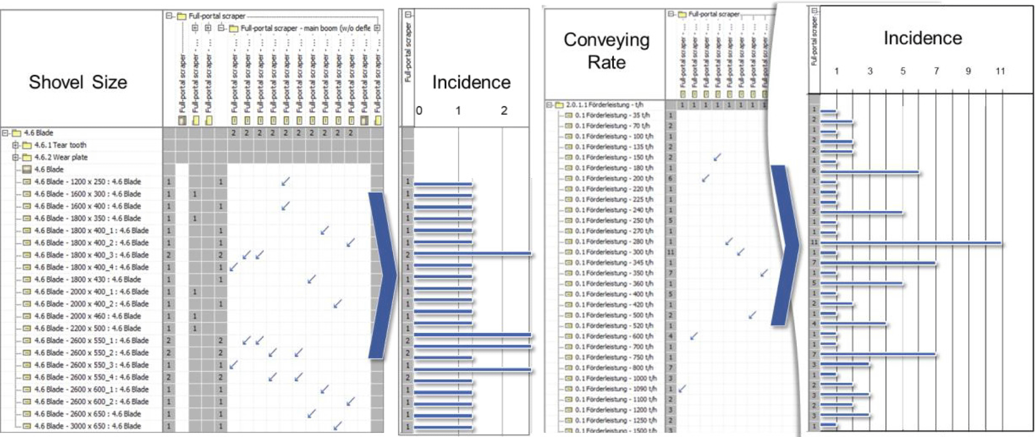
A product model (C3) is created on the basis of documents (e.g. product requirements document) and CAD data from an existing portal scraper (C4), which compares the respective functions and components to the objectives, requirements and boundary conditions. On the basis of this, a reference product model (C2) can be derived, with which further portal scrapers are transferred to the SysML model. The reference product model (C2) is iteratively adapted and converted into a modular reference model (B2). The components, their features and dependencies are stored in the reference model of the modular kit. For example, the entirety of the scraper buckets (B3) can be visualized. Based on the matrix-based illustration, it can be determined that the different scraper buckets are largely developed individually for each machine (Figure 19 left). If this variance of components is compared to the much lower variance of the requirements for the capacity of the buckets (Figure 19 right), further investigations can be conducted to determine whether the scraper buckets can be reduced to a predefined number of modules (Bursac et al. Reference Bursac, Albers and Schmitt2016b ).
Variants of scraper bucket sizes (left) and requirements regarding bucket capacities (right) (Bursac et al. Reference Bursac, Albers and Schmitt2016b ).
In this case, it can be described with the aid of the fractal character that, for example, the scraper buckets can be modularly designed, as they are based on the platform design type. The hat can also be carried out on the series design type. This way, different methods of standardization can be used on different levels of the system. The results can then be integrated into the SysML model and thus a consistent modular kit can be depicted. Especially in the case of the highly iterative development processes, this approach offers potential, since the model contains all relevant information and the evaluation of various documents (e.g. product requirements documents) is no longer required (Bursac et al. Reference Bursac, Albers and Schmitt2016b ).
This case study has supported the early development stages of a portal scraper in 6 months of modeling and application time in the analysis of potential. Approx. 1000 elements were generated in the model. Five fields of the framework (see Figure 3) could be covered. The study was carried out with the use of SysML (see Table 1).
5 Conclusion, discussion and outlook
5.1 Conclusion
The aim of the research is to validate the capabilities of the MBSE approach in the modular development of industrial enterprises to gain a better understanding of how the MBSE approach needs to be further developed to support modular design in an industrial context. In summary, the following results have been achieved:
(1) Model-based approaches to support the development of modular kits should depict the continuous further development of a modular kit in the sense of PGE. Thus, the approach is able to map the time offsets in modular development and the long life horizon of a modular system.
(2) Model-based approaches to support the development of modular kits should consistently map both the modular kit with its modules and the entirety of the products configurable with it. Within the scope of the studies presented here, this has led to extensive models with an average of several thousand elements.
(3) Model-based approaches to support the development of modular kits should enable reuse of the models in the sense of the PGE due to the high number of elements. In case study 6.2, a transfer variation of more than 80% of the model elements could be observed.
(4) Model-based approaches to support the development of modular kits should enable the alternation between different views regarding modular kit versus the product view on the one hand and reference product model versus the product model on the other hand. A modeling of these views was possible within the framework of the studies with the help of the framework
(a) In different system levels: subsystem (e.g. Case Studies 2 & 3) as well as entire product (e.g. Case Studies 1, 4 & 5).
(b) In different industries: automotive (e.g. Case Studies 1,2 & 3) as well as mechanical engineering (Case Studies 4 & 5).
(c) In different time phases of product development: early stages (e.g. Case Studies 1 & 5) as well as series development (Case Studies 2, 3 & 4).
(5) Model-based approaches to support the development of modular kits should enhance interdisciplinary cooperation. SysML offers the basis for this, but still shows development potential. In Case Study 3, for example, more than a third of the modeling effort was not spent on core activities such as system understanding and model generation.
Due to the aim to validate MBSE in the development of modular kits, a broad methodological approach has been applied. Therefore, the findings obtained have a wide range. At the same time, however, it can be shown that these individual findings can be found in a similar way in existing literature. For example, aspects such as the necessary longevity of architectures (Finding 1) and the resulting reusability of elements (Finding 3) are also dealt with in the works of Kim & Moon or Greve & Krause. Another example is the configurability of modules and products in the same model (Finding 2) in (Sosa et al. Reference Sosa, Eppinger and Rowles2004). Nevertheless, this article with its validation in an industrial environment crossing through different industries and system levels, has its main contribution in showing which central aspects have to be further developed in order to use MBSE to support real-world problems of industrial modular design with added value.
5.2 Discussion
It is uncontroversial that modular design is a well-established and effective measure to enable significant cost savings by reducing a company’s overall internal component diversity and correlating complexity. However, modules and their development can lead to an increase in complexity for the developer himself, since technical, scheduling and organizational requirements and boundary conditions for a module are much more diverse compared to those of a non-modular component.
To support the developers of modules, a framework was developed which supports the modeling by providing different layers for the modeler, which are iteratively filled and modeled. Using this framework, five case studies were conducted. Thus, the applicability of the MBSE approach with the help of the framework in modular design was demonstrated in various companies and industries. The methodical approach used during the realization of the models allows a consistent modeling of modular kits and products. In addition, requirements engineering could be made more efficient and the models could be reused for knowledge management. The approach led to an added value in other industries in the transfer studies as well.
The different case studies, however, also indicated limitations. In particular, the time required for the development of the models must be mentioned. Within the framework of their final thesis students have developed and expanded the models. The respective theses lasted 6 months, minus the training period and the time needed to write the thesis and engaged the students as a modeler. As case study 3 shows, part of the effort is due to the modeling itself. However, much of the work is also due to the improvement potential of the MBSE tools. In particular, the lack of an interface between SysML and CAD would save a lot of time, especially in the modeling of embodiment systems. It has been shown that it is more effective to train few experts on modeling. In the role of a moderator, they have involved different experts in the development of the model. As a result, it was not necessary for the developers to have broad modeling skills. By increasing the use of illustrations and CAD screenshots in the SysML models, most developers were able to understand the modeling well.
The high workload of modeling in the daily life of developers, can only be justified, if the models can be reused according to PGE. The reference product models provide a very good foundation for this. Through the consistent modeling based on the framework, the reusability was ensured. This way it is possible to efficiently model during the workshop and, for example, regarding the element ‘engine’ of the reference product model, it can be quickly decided whether an existing element of the modular kit is to be linked or a new generation of the engine is to be developed. Only new technologies such as automated driving require an adaptation of the reference product model (see case study 1). A consistent use of the framework according to PGE saves large modeling time and thus expenditure of time (see case study 2).
The dilemma of individualization vs. product cost, which is superior to modular development, can also be met in another way. Alternative solutions can be found, for example, in comprehensive literature about mass customization (see e.g. Tseng & Hu Reference Tseng and Hu2014, Fogliatto et al. Reference Fogliatto, Da Silveira and Borenstein2012). Here, approaches of Additive Manufacturing (AM) appear promising (Hu Reference Hu2013). However, it should be noted that the products must be developed in the sense of design for AM (Vayre et al. Reference Vayre, Vignat and Villeneuve2012).
To sum it up, modular design is in need for MBSE methods that allow for the modeling of the alternating effects between single modules and the products assembled from the modules. With several studies applied in the field of vehicle modular kits, the results show that reference product models support the ongoing development of modular systems, yet up to 80% of the model elements can be reused (see Case Study 2), thus keeping the modeling effort at a tolerable level. The aspect of the connection of PGE and modular design offers further research needs, which is currently being carried out as part of a comprehensive study. The current situation is briefly outlined in the outlook.
5.3 Outlook
In an ongoing research project at an international automotive supplier the presented modeling framework is used in the modular design process for mechatronic drives. On the basis of functional structures and requirements of individual products models exist, which are similar to a reference model of a modular kit. Starting from the system level (total drive), the requirements are broken down to the domain level. There are currently independent solutions for the domains software, hardware and mechanics. These should first be assimilated and linked to a system with a holistic, mechatronic view. In the case of mechanics, it is not yet possible to break down system requirements into individual components because of the resulting mechatronic interactions in the design process. To develop a holistic model of a modular kit, specific implementations from the individual products are required. These must be technically captured in a first step and have to be linked to the specific requirements (product models). Using this information, existing models can be extended and a model of a modular kit can be derived. This can be based on the requirements on the system level and support the selection process of the components. In addition, the variety of variants can be detected and controlled in a model of a modular kit.
In another ongoing research project at a machine tool manufacturer the presented modeling framework is used to introduce and roll out a modular kit as well as ensuring sustainability.
The manufacturer has already introduced a modular kit for one of its product families. The procedure of the introduction can be described by the modeling framework. For further enhancement with new technologies, appropriate methods and processes are required which – according to the framework – derive models of existing products of the technologies in order to explicate them deductively into real modules and products which follow the modular kit regulations. Overall consistency and quality of models has to be ensured by iterative processes in order to account the aspect of a continuous modular kit development within the product generation development. It is examined in which way the modeling framework can support describing, planning and developing modular kit generations. Methods and processes, which acknowledge the particularities of a continued modular kit development in this context, are of special interest.
According to strategic requirements and constraints as well as restrictions specified by the modular kit, modules need to be developed continuously (generation development). By superordinate planning and a corresponding reference process it has to be ensured that subsystems of the modular kit within a single generation are compatible to each other according to the defined combinatorics. Also, the integration of new functions and kit parts as well as new modules has to be ensured. Another aspect that has to be considered is the structure of the modular kit which also shows effects on the generation development.
Acknowledgments
The developments of the models were carried out with the help of final theses of graduate students. The authors therefore would like to thank the following students: Dominik Brandt, Stefan Jantoß, Lukas Kurowicki, Galina Rachenkova, Marc Ölschläger, Thomas Schmitt und Benjamin Weissinger.


 Open access