

1 Introduction
High-power laser facilities like National Ignition Facility (NIF) in the United States, Shenguang (SG) series laser facilities in China, and Laser Megajoule (LMJ) in France are designed to create the ignition of a deuterium–tritium nuclear fusion target in a laboratory setting[Reference Haynam, Wegner, Auerbach, Bowers, Dixit, Erbert, Heestand, Henesian, Hermann, Jancaitis, Manes, Marshall, Mehta, Menapace, Moses, Murray, Nostrand, Orth, Patterson, Sacks, Shaw, Spaeth, Sutton, Williams, Widmayer, White, Yang and Van Wonterghem1–Reference Cavailler3]. In such a large laser system, the laser beam is generated by the Injection Laser System (ILS), which is made up of the master oscillator (MOR), the Preamplifier Module (PAM), the Input Sensor Package (ISP), and the Preamplifier Beam Transport System (PABTS)[Reference Bowers, Burkhart, Cohen, Erbert, Heebner, Hermann and Jedlovec4]. As a part of PAM, the Nd:glass diode-pumped regenerative amplifier (Regen) plays a crucial role in many aspects[Reference Bowers, Burkhart, Cohen, Erbert, Heebner, Hermann and Jedlovec4–Reference Heebner6]: first, it is the first stage of amplification in the PAM and represents the largest gain component in the high-power laser facilities, with the gain of about $10^{7}$
; second, the regenerative amplifier provides several advantages of the laser output, including high output beam quality, high-energy stability, and low square-pulse distortion (SPD).
$10^{7}$
; second, the regenerative amplifier provides several advantages of the laser output, including high output beam quality, high-energy stability, and low square-pulse distortion (SPD).
We have developed an Nd:glass diode-pumped regenerative amplifier, which has been used in the SG-II laser facility since 2009. The regenerative amplifier works at 1 Hz, and its output energy is 10 mJ at a pulse width of 3 ns, corresponding to a total gain of about $10^{7}$
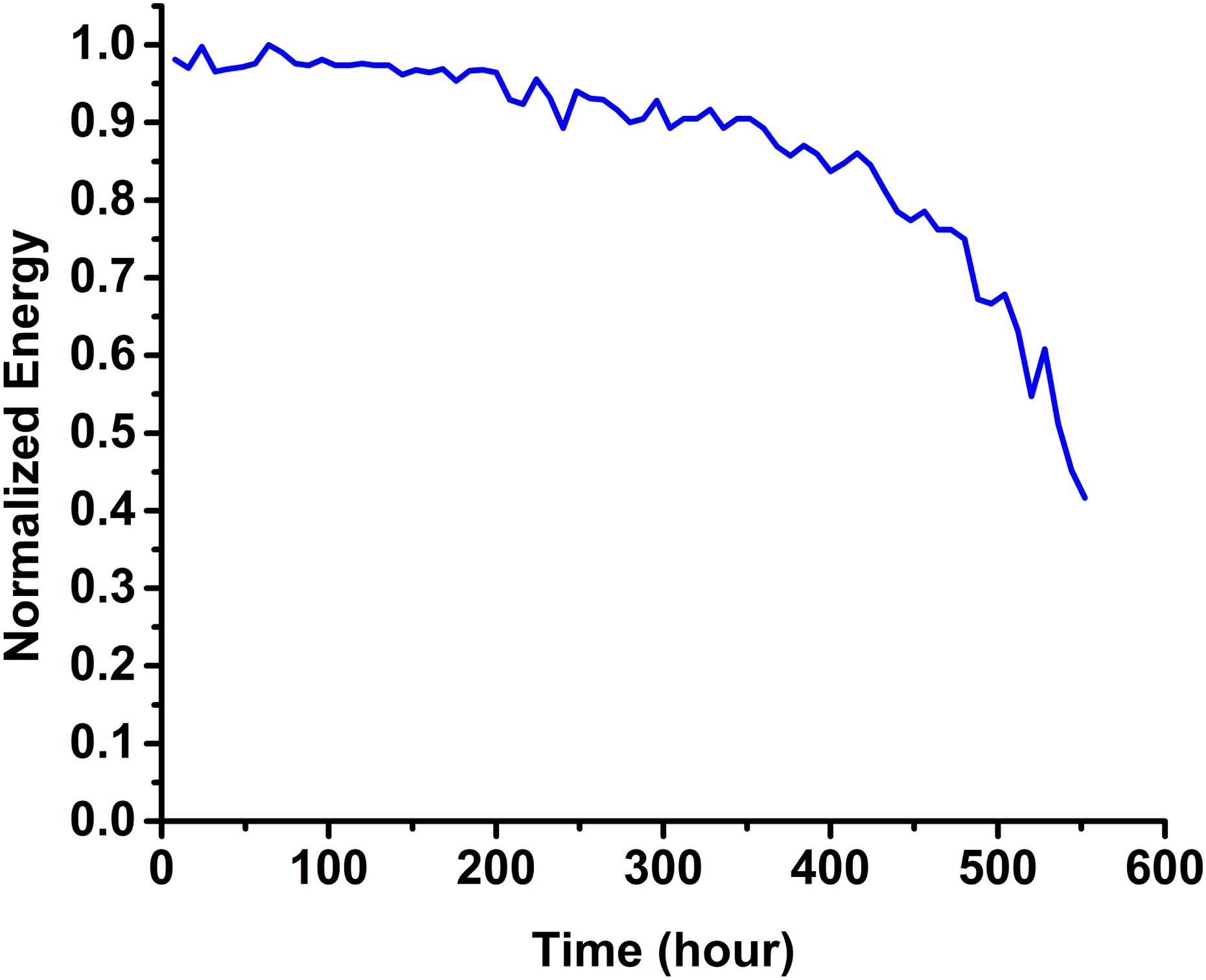
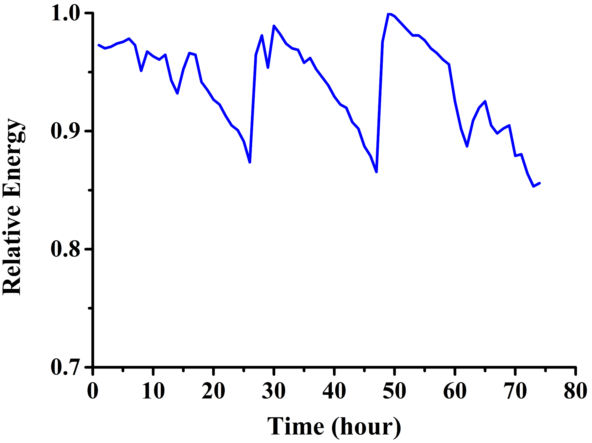
. Its energy stability is 0.2% rms within 6 h, and SPD value is less than 1.35[Reference Peng, Wang, Zhang, Huang, Fan and Li7]. Although the regenerative amplifier has excellent energy stability, its output energy will gradually drop after a long-term operation. And the energy decreases faster as operation time grows. Figure 1 displays the output energy of the regenerative amplifier over a 3.5-month period, which has dropped by almost 60%. To our knowledge, this is a common problem for most high-power solid-state lasers and is the most severe challenge to apply them in large laser systems.
$10^{7}$
. Its energy stability is 0.2% rms within 6 h, and SPD value is less than 1.35[Reference Peng, Wang, Zhang, Huang, Fan and Li7]. Although the regenerative amplifier has excellent energy stability, its output energy will gradually drop after a long-term operation. And the energy decreases faster as operation time grows. Figure 1 displays the output energy of the regenerative amplifier over a 3.5-month period, which has dropped by almost 60%. To our knowledge, this is a common problem for most high-power solid-state lasers and is the most severe challenge to apply them in large laser systems.
The reason of the Regen energy decline is that there are damages in optical components, which can be observed directly by the naked eye. Therefore, finding out origin of these optical damages is the priority to improve operation lifetime of the Regen. There are two possible reasons for such optical damages: one is that damage threshold of optical components in Regen cavity may be not high enough to prevent laser induced damages (LIDs), which result from defects on the surfaces or in the bodies of these components[Reference Chow, Runkel and Taylor8–Reference Negres, Burke, DeMange, Sutton, Feit and Demos10]; the other is that laser induced contamination (LIC) may happened on the surfaces of optical components in the Regen cavity, i.e., the formation of highly absorbing deposits on optical surfaces caused by the interaction of the laser with molecules which outgas from organic materials in vacuum or molecules of dust and gas in contaminated air environment[Reference Riede, Allenspacher, Schröder, Wernham and Lien11–Reference Riede, Schroeder, Bataviciute, Wernham, Tighe, Pettazzi and Alves14]. LIC results in degradation of the properties of optical components, which contributes to an overall transmission loss and eventual irreversible damages of optical components.
In this work, we research optical damages on the surfaces of optical components in the Regen cavity in detail. By a series of experiments, the origin of these damages has been found out. Base on this work, our Nd:glass regenerative amplifier has been improved to suppress optical damages. Eventually, the energy decline of the Regen after improvement after 6-month operation is lower than 4%, which meets the requirement for operation lifetime of the Regen in high-power laser facilities.
Normalized output energy of the regenerative amplifier as a function of time over a 3.5-month period.
2 Determination of the origin of damages on optical components surfaces in regenerative amplifiers
In order to investigate which results in damages on surfaces of optical components, LID or LIC, three experiments listed below were carried out.
2.1 LID threshold test for optical components used in Regen cavity
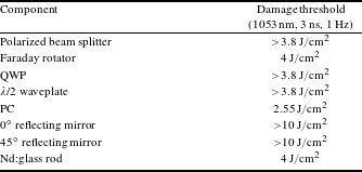
Damage thresholds of optical components used in Regen cavity were tested by a home-made laser damage test system with real-time damage event imaging and detection[Reference Wang, Wei, Jiang, Wang, Qiao, Guo, Fan and Li15]. The test followed by a standard 1-on-1 testing regime. The test results are shown in Table 1, in which damage thresholds of all optical components in Regen cavity are larger than $2.5~\text{J}/\text{cm}^{2}$
. Since the peak energy fluence in the Regen cavity is about
$2.5~\text{J}/\text{cm}^{2}$
. Since the peak energy fluence in the Regen cavity is about $1~\text{J}/\text{cm}^{2}$
, it can be inferred that LID is not the ultimate cause of damages on surfaces of optical components in the Regen.
$1~\text{J}/\text{cm}^{2}$
, it can be inferred that LID is not the ultimate cause of damages on surfaces of optical components in the Regen.
Damage threshold of optical components used in the Nd:glass Regen.
2.2 Observation of damage morphology by an optical microscope
Morphology of damage sites can be observed by an optical microscope (KH-8700, HIROX-USA, Inc) with high magnification. The KH-8700 microscope contains an integrated stepping motor which allows for fast, smooth, and accurate scanning with $0.05~\unicode[STIX]{x03BC}\text{m}$
per pulse precision and 30 mm of automated travel distance, which makes 3D model imaging and 3D height measurement available. In Figures 2 and 3, the morphology of damage spots of a quarter waveplate (QWP) and a window glass (WG) of the Pockels cell (PC) in the Regen is shown with
$0.05~\unicode[STIX]{x03BC}\text{m}$
per pulse precision and 30 mm of automated travel distance, which makes 3D model imaging and 3D height measurement available. In Figures 2 and 3, the morphology of damage spots of a quarter waveplate (QWP) and a window glass (WG) of the Pockels cell (PC) in the Regen is shown with $1000\times$
and
$1000\times$
and $350\times$
magnification, respectively. It can be seen from these figures that there are some deposits on damage sites compared to undamaged sites. And the thickness of deposited material on the QWP and WG is 4.67 and
$350\times$
magnification, respectively. It can be seen from these figures that there are some deposits on damage sites compared to undamaged sites. And the thickness of deposited material on the QWP and WG is 4.67 and $6.16~\unicode[STIX]{x03BC}\text{m}$
, respectively, which can be read from Figures 2(b) and 3(b). Figure 4 shows the morphology of the whole damage sites on the WG surface of PC in the Regen. From the figure, we can see that deposits only exist in the region on which the laser pulse irradiates, which is a typical characteristic of LIC[Reference Riede, Schroeder, Bataviciute, Wernham, Tighe, Pettazzi and Alves14]. There are less and smaller deposits on the central parts of this region. The reason for this may be that the spatial center of laser beam has the highest energy fluence, which has a clean effect for the deposits and results in removal of the center part of deposits where laser intensity is highest at the beginning of their growth. Moreover, as a comparison, the morphology of a damage spot on an Nd:glass rod surface caused by LID when laser energy fluence exceeds its damage threshold in the LID test experiment mentioned in Section 2.1 is shown in Figure 5. It is obvious that on the damage site the coating was peeled off and no deposits were observed, though after damage the surface shape of the Nd:glass rod had distorted severely.
$6.16~\unicode[STIX]{x03BC}\text{m}$
, respectively, which can be read from Figures 2(b) and 3(b). Figure 4 shows the morphology of the whole damage sites on the WG surface of PC in the Regen. From the figure, we can see that deposits only exist in the region on which the laser pulse irradiates, which is a typical characteristic of LIC[Reference Riede, Schroeder, Bataviciute, Wernham, Tighe, Pettazzi and Alves14]. There are less and smaller deposits on the central parts of this region. The reason for this may be that the spatial center of laser beam has the highest energy fluence, which has a clean effect for the deposits and results in removal of the center part of deposits where laser intensity is highest at the beginning of their growth. Moreover, as a comparison, the morphology of a damage spot on an Nd:glass rod surface caused by LID when laser energy fluence exceeds its damage threshold in the LID test experiment mentioned in Section 2.1 is shown in Figure 5. It is obvious that on the damage site the coating was peeled off and no deposits were observed, though after damage the surface shape of the Nd:glass rod had distorted severely.
Morphology of a damage site on a QWP surface in the Regen cavity. (a) Optical microscopy of the QWP damage site with $1000\times$
magnification; (b) contour map of the QWP damage site.
$1000\times$
magnification; (b) contour map of the QWP damage site.

Morphology of a damage site on a WG surface of the PC. (a) Optical microscopy of the WG damage site with $350\times$
magnification; (b) contour map of the WG damage site.
$350\times$
magnification; (b) contour map of the WG damage site.

Morphology of the whole damage sites of WG surface of PC in the Regen.

Morphology of a damage site on an Nd:glass rod surface caused by LID in the LID test experiment when laser energy fluence exceeds the damage threshold of the Nd:glass rod surface.

(a) Raman spectra of deposits on the damaged QWP surface in comparison to that of carbon; (b) Raman spectra of deposits on the surface of damaged WG of PC in comparison to that of carbon.

2.3 Chemical analysis of deposited material on the surfaces of damaged optical components
Chemical constituents of deposited material on damaged optical components surfaces were investigated by Raman spectroscopy. By comparison with the integrated database of Raman spectra, the Raman spectra of these deposits can be matched with Raman spectrum of carbon, which is a basic chemical element contained in organic compounds. This suggests that the deposited material on surfaces of damaged optical components may be organics. Figure 6(a) and 6(b) show the Raman spectra of deposits on the QWP surface and WG surface of the PC in the Regen, respectively.
It can be concluded from the three experiments illustrated above, that the origin of damages in the Regen is LIC rather than LID, since damage thresholds of optical components used in Regens is much larger than the peak energy fluence in the Regen cavity, and deposited material which contains element carbon has been discovered on the damage sites of optical components surfaces.
3 Determination of the pathway for LIC in regenerative amplifiers
From the experiments described in Section 2, LIC is the primary cause of damages on optics surfaces in the Regen cavity. LIC was proposed by Wernham et al. during the research of frequency-tripped Nd:YAG lasers on space[Reference Riede, Allenspacher, Schröder, Wernham and Lien11–Reference Riede, Schroeder, Bataviciute, Wernham, Tighe, Pettazzi and Alves14]. According to their research, LIC is caused by the interaction of the laser with molecules which outgas from organic materials in vacuum on the optical surfaces, and it will form highly absorbing deposits on the surface of optics. Besides laser systems on space, it has been discovered that LIC also occurs in high-power laser systems in an air environment, resulting in a formation of an obstructive haze on optics, which degrades optics performance, such as transmission (for optics with antireflective coating) or reflection (for optics with reflective coating) and eventually leads to laser damages on optics surfaces[Reference Hovis, Shepherd, Radcliffe and Maliborski16–Reference Guéhenneux, Bouchut, Veillerot, Pereira and Tovena18]. In this section, three experiments are carried out to identify how LIC is generated in regenerative amplifiers.
3.1 Measurement of concentrations of airborne molecular compounds in the Regen cavity
It has been reported that interaction between laser radiation and nearby outgassing species results in the LIC of optical surfaces on space. In order to investigate if outgassing of organics is the primary cause of LIC in the Regen cavity, we first measured airborne molecular compound (AMC) concentrations in the regenerative amplifier.
The measurement was done using an XAD-2 tube, connected to an air sampling pump (SKC AIRCHEK 2000). The sampling lasted 60 min at a flow of 2 L/min corresponding to a 120 L air sample in the Regen. After sampling, the sampling tube was closed and kept at a temperature less than $4^{\circ }\text{C}$
until receipt at analytical laboratory, after which they were refrigerated at less than or equal to
$4^{\circ }\text{C}$
until receipt at analytical laboratory, after which they were refrigerated at less than or equal to $4^{\circ }\text{C}$
. Then the sample was extracted and analyzed by gas chromatography–mass spectrometry (GCMS). All sampling and measurement work mentioned above was done by ALS analytical testing CO, LTD.
$4^{\circ }\text{C}$
. Then the sample was extracted and analyzed by gas chromatography–mass spectrometry (GCMS). All sampling and measurement work mentioned above was done by ALS analytical testing CO, LTD.
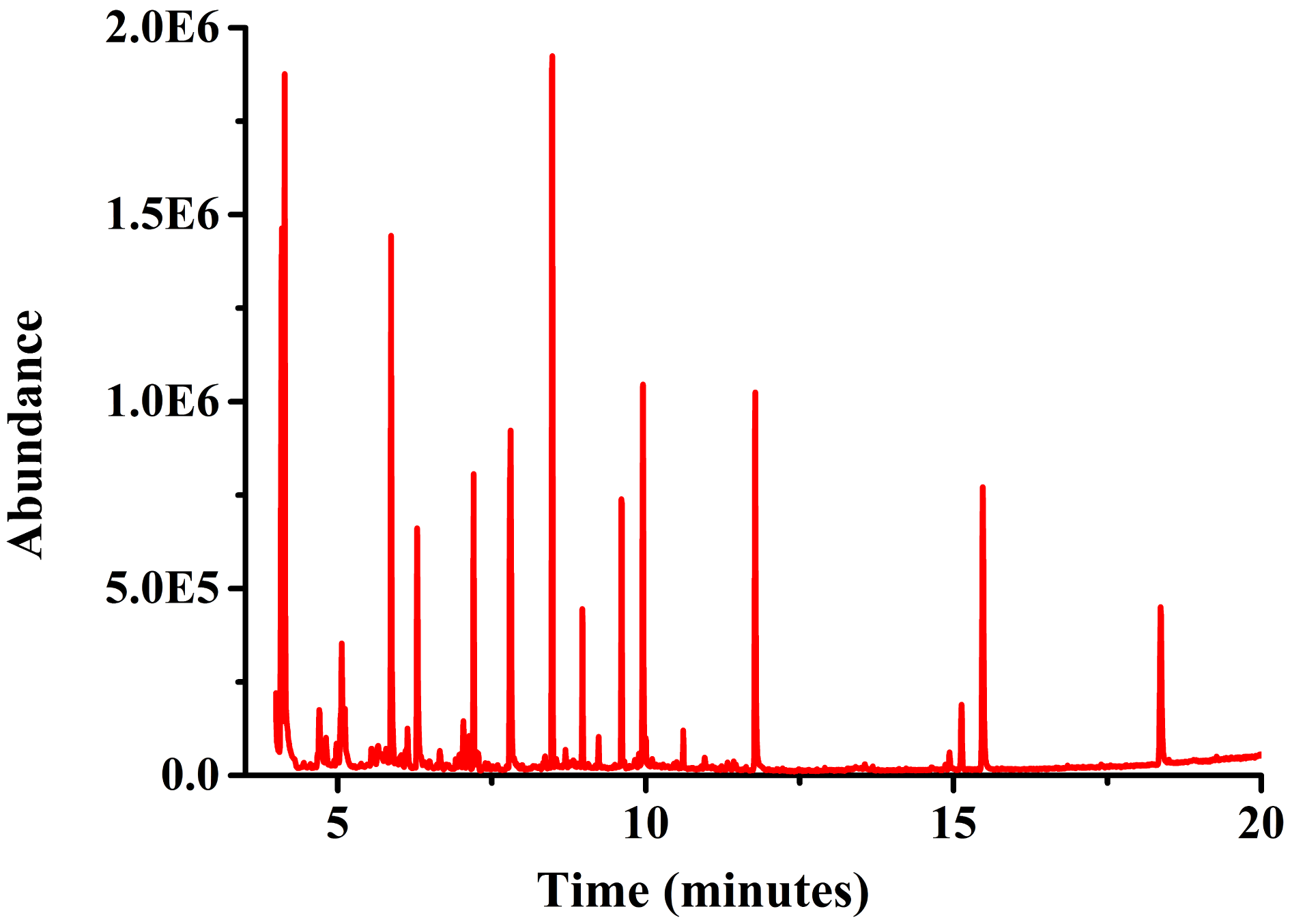
The total ion current chromatogram (TIC) is shown in Figure 7. The top ten AMCs in the sample, whose concentrations were highest, are listed in Table 2. Concentration of each AMC is less than 10 ppbv, and the total AMC concentration in the sample is a mere 42 ppbv, almost in the same order of magnitude of that in a general air environment, which indicates that the outgassing of organic materials in the Regen is at a very low level.
The TIC for the AMC sampling made in the Regen cavity.
The top ten AMCs with highest concentrations.

3.2 Output energy performance of the regenerative amplifier after installation of a clean dry nitrogen purge system
If AMCs in the Regen cavity are generated by outgassing of organics, their concentrations should be decreased when clean dry nitrogen (CDN) is supplied to the inner of a regenerative amplifier, which will make the Regen output energy drop more slowly than it used to in the long-term operation. In the experiment of this section, a CDN purge system is installed in a regenerative amplifier to investigate whether the AMCs stem from outgassing of organic materials.
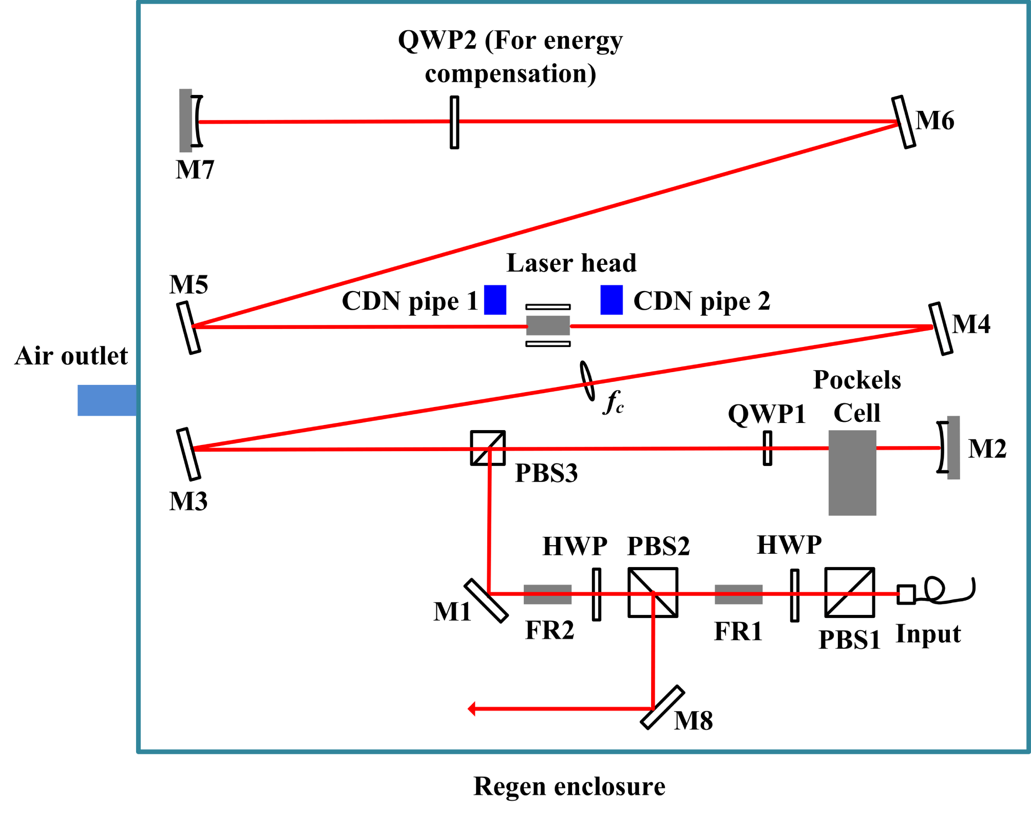
The layout of the regenerative amplifier with a CDN purge system is shown in Figure 8. Two clean stainless steel pipes are installed near both ends of the Nd:glass laser head, which suffers from LIC frequently. CDN with the cleanliness level less than Class 10 standard is purged into the Regen cavity by these two pipes. The flow rate of CDN purge system is 3 L/min. However, as is shown in Figure 9, when the Regen worked, its output energy declined more than 10% after 26 h of operation, much faster than it used to. Then the energy was compensated to its initial value by QWP2, which had preattenuated output energy of the Regen, but the energy decreasing rate still remained the same.
The regenerative amplifier with a CDN purge system, which is installed in the Regen cavity.
The output energy of the Regen with a CDN purge system working versus time.
Then we turned off the Regen, and uncovered its enclosure. It was found that almost all the optical components with antireflective (AR) coatings were damaged on surfaces. All these damages had been proved to be organic deposits by the optical microscope and Raman spectrometer. It should be mentioned that no deposits have been discovered in reflecting mirrors. And the reason for this may be that the energy fluence on the surfaces of reflecting mirrors is almost twice as much as that on AR coatings, since energy fluence had been enhanced by incident beam and reflected beam, and the high fluence laser beam cleaned the deposits on the surfaces of reflecting mirrors at the beginning of their growth.
It can be deduced from the experiments in Sections 3.1 and 3.2 that outgassing of organic materials is not the primary cause of LIC in the Regen, since: first, the total concentration of AMCs in the Regen cavity is on the same level of that in a general air environment; and second, when a CDN purge system worked in the Regen cavity, the output energy performance of the Regen was even worse than it used to be. The latter implies that there might exist aerosols in the Regen cavity, which flowed in the horizontal direction when the CDN purge system worked.
3.3 Investigating origin of aerosols in the Regen cavity
To investigate how aerosols are generated in the Regen cavity, another regenerative amplifier with no CDN purge system is chosen for experiment. After about a 3-month operation, its output energy has dropped by 50%. When the Regen was turned off and its enclosure was uncovered, some organic deposits were discovered on a surface of QWP2. However, QWP2 was mounted in a vacuum compatible piezo rotation stage with very low outgassing rate. There should be no organic deposits on the surface of QWP2 if LIC stemmed from outgassing of organic materials. Therefore, the appearance of deposits on the surface of QWP2 further validates our inference that outgassing of organic materials is not the primary cause of LIC in the Regen cavity.
It was observed that a fraction of the laser beam (about 0.5%), which propagated from the second end mirror M7 to QWP2, was reflected by the second surface (S2 surface) of QWP2 with AR coatings, as shown in Figure 10(a). The reflective beam, which reflected from S2 surface of QWP2, is called ghost beam. This ghost beam was first transmitted to M7 and reflected by it. And finally, the ghost beam illuminated on the gap of the rotation stage, in which QWP2 was mounted, as shown in Figure 10(b). There was a lot of vacuum compatible grease in the gap. Although the energy of the ghost beam was as low as $50~\unicode[STIX]{x03BC}\text{J}$
, its energy fluence was almost on the same level as energy fluence of the main laser beam (
$50~\unicode[STIX]{x03BC}\text{J}$
, its energy fluence was almost on the same level as energy fluence of the main laser beam ( $1~\text{J}/\text{cm}^{2}$
), since it was focused twice by the concave end mirror M7. This fluence is high enough to generate aerosols.
$1~\text{J}/\text{cm}^{2}$
), since it was focused twice by the concave end mirror M7. This fluence is high enough to generate aerosols.
(a) The diagram which describes that the ghost beam irradiates on the gap of the rotation stage of QWP2. The solid red line represents propagation of the main laser beam, and the dashed blue line represents propagation of the ghost beam generated by reflection of the main beam from a surface of QWP2. (b) A photo of rotation stage.

Subsequently, it was discovered that in the vicinity of each damaged optical component, ghost beams can be found illuminating on organic materials. For instance, we found that the external aperture stop of the stainless steel window holders (shown in Figure 11) of the damaged PC (Fastpulse Technology, Inc.) was not clean enough. There was a lot of residual lubricant on the aperture stop. The lubricant, which should have been cleaned away before the PC left the factory, might be introduced by the manufacturer when the PC was produced. And unfortunately, the aperture stop was illuminated by ghost beams from PBS3 and QWP1, which might produce aerosols near the PC which led to LIC on WG surface of PC. The same situation also existed in the Nd:glass laser head.
A photo of the PC used in the Regen. The external aperture stop of the stainless steel window holders was marked with a red circle.

Therefore, the generation process of LIC on optical components should be: first, ghost beams irradiate on organic materials near optical components; second, aerosols are generated in air near these optical components by interaction of ghost beams and organic materials; then, the main laser beam illuminates aerosols, which results in photochemical and photothermal reactions of aerosols on surfaces of nearby optical components, and will eventually give rise to damages.
4 Experiments of suppression of LIC in the regenerative amplifier
To verify the conclusion of generation process of LIC in Regens, which was illustrated in Section 3.3, several improvements have been made in the regenerative amplifier: (1) all mechanical components in the Regen, including the ones supplied by manufacturers of optical components (PC supplied by Fastpulse Technology, Inc., for instance), were cleaned by ethanol in a supersonic tank; (2) all ghost beams generated by optical components with AR coatings were found, and blocked by beam traps; (3) all nonmetal materials were shielded by clean aluminum foil.
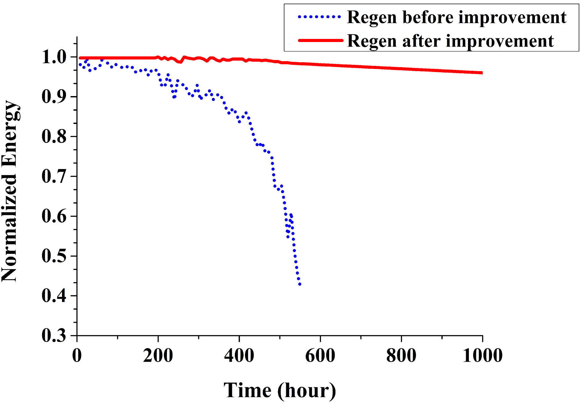
After the regenerative amplifier was modified, it operated for 6 months to examine its long-term output energy performance. The output energy of Regen as a function of time is shown in Figure 12, which illuminates that the decline of Regen output energy after 1000 h of operation is less than 4%, far lower than it used to be. This indicates that laser irradiation on organic materials by ghost beams is the primary cause of energy decrease of the regenerative amplifier in the long-term operation. This operation lifetime meets the requirement for the Nd:glass regenerative amplifier used in high-energy laser facilities.
5 Conclusions
In conclusion, damages on the surface of optics, which degraded output energy performance of the Nd:glass regenerative amplifier, were investigated in this work. By a series of experiments, it was discovered that these damages resulted from laser irradiation on organic materials by ghost beams, which led to LIC. There exist some ghost beams in the Regen cavity, which irradiate on organic materials near optical components. Interactions of ghost beams and organic materials give rise to aerosols near these optical components. Then, the main laser beam illuminates on aerosols, which results in photochemical and photothermal reactions of aerosols on the surfaces of nearby optical components, and will eventually give rise to their surface damages.
Normalized output energy of the regenerative amplifier as a function of time before and after improvement.
Therefore, controlling of propagation of ghost beams in the Regen cavity is very important to the operation lifetime of the Regen. In order to increase its operation lifetime, the following improvements should be made: (1) reduce the use of nonmetal materials in the Regen; (2) all mechanical components, including the ones supplied by manufacturers of optical components (PC supplied by Fastpulse Technology, Inc., for instance), should be cleaned; (3) all ghost beams generated by optical components with AR coatings should be found, and blocked by beam traps; (4) all nonmetal materials used in the Regen should be shielded by clean aluminum foil.
The output energy of the regenerative amplifier after improvements dropped by 4% after 1000 h of operation, much less than it used to, 60% after 560 h of operation. The operation lifetime is expected to be further improved if cleanliness of all components used in the Regen can be controlled less than Level 100-A/10. Eventually, it should be noted that the research of this work can be applied to all kinds of solid-state laser systems with high-energy output.
Acknowledgement
This research was supported by National Natural Science Foundation of China under Grant No. 61405211.


 Open access