


1. Introduction
Flow around a cylinder that is forced to rotate has been studied both when the cylinder is under constant rotation (Diaz et al. Reference Diaz, Gavaldà, Kawall, Keffer and Giralt1983; Badr et al. Reference Badr, Coutanceau, Dennis and Menard1990; Mittal & Kumar Reference Mittal and Kumar2003; Kumar, Cantu & Gonzalez Reference Kumar, Cantu and Gonzalez2011; Seyed-Aghazadeh & Modarres-Sadeghi Reference Seyed-Aghazadeh and Modarres-Sadeghi2015) and when the cylinder is under a periodic rotation (Tokumaru & Dimotakis Reference Tokumaru and Dimotakis1991, Reference Tokumaru and Dimotakis1993; Shiels & Leonard Reference Shiels and Leonard2001; Thiria, Goujon-Durand & Wesfreid Reference Thiria, Goujon-Durand and Wesfreid2006; Du & Dalton Reference Du and Dalton2013). The rotation is quantified using a rotation rate defined as the ratio of the surface velocity of the cylinder and the incoming flow velocity,
 $\alpha =D\omega /(2U)$
, where
$\alpha =D\omega /(2U)$
, where
 $D$
is the cylinder diameter,
$D$
is the cylinder diameter,
 $\omega$
is its angular velocity and
$\omega$
is its angular velocity and
 $U$
is the incoming flow velocity. When the cylinder is under constant rotation, it is shown both numerically and experimentally that for small rotation rates, vortices are still shed in the wake of the cylinder, at a frequency equal to that predicted by the Strouhal law, but at an angle with respect to the incoming flow due to the cylinder’s constant rotation. For a range of higher rotation rates, however, the shedding is suppressed and when the rotation rate is increased beyond this range, a one-sided large vortex is shed in the wake of the cylinder. When the cylinder is forced to rotate periodically, then there is a range of rotation rates and imposed frequencies within which the shedding frequency stays equal to the rotation frequency. Within this range, the shedding frequency in the wake of the cylinder can be controlled externally and deviates from that predicted by the Strouhal law. For forcing frequencies larger than the Strouhal frequency, however, this external control of shedding frequency is limited to an area very close to the cylinder, a region that is referred to as a lock-in region (Thiria et al. Reference Thiria, Goujon-Durand and Wesfreid2006; Kumar et al. Reference Kumar, Lopez, Probst, Francisco, Askari and Yang2013) (not to be confused with the lock-in range in a vortex-induced vibration (VIV) response). Farther from the cylinder, the shedding frequency goes back to a value slightly smaller than the Strouhal frequency. Recently, it has been shown that by imposing periodic rotation at a desired rotation frequency and, therefore, controlling the shedding frequency of the vortices in the wake of the cylinder, one can impose desired motions on objects placed downstream (Currier, Carleton & Modarres-Sadeghi Reference Currier, Carleton and Modarres-Sadeghi2021; Carleton, Sup & Modarres-Sadeghi Reference Carleton, Sup and Modarres-Sadeghi2022; Carleton & Modarres-Sadeghi Reference Carleton and Modarres-Sadeghi2024). All these studies have been conducted at Reynolds numbers larger that the critical Reynolds number for the onset of shedding in the wake of a fixed cylinder, i.e. cases where the vortices are already shed in the wake of the fixed cylinder, and forcing the cylinder only changes the frequency and strength of these vortices.
$U$
is the incoming flow velocity. When the cylinder is under constant rotation, it is shown both numerically and experimentally that for small rotation rates, vortices are still shed in the wake of the cylinder, at a frequency equal to that predicted by the Strouhal law, but at an angle with respect to the incoming flow due to the cylinder’s constant rotation. For a range of higher rotation rates, however, the shedding is suppressed and when the rotation rate is increased beyond this range, a one-sided large vortex is shed in the wake of the cylinder. When the cylinder is forced to rotate periodically, then there is a range of rotation rates and imposed frequencies within which the shedding frequency stays equal to the rotation frequency. Within this range, the shedding frequency in the wake of the cylinder can be controlled externally and deviates from that predicted by the Strouhal law. For forcing frequencies larger than the Strouhal frequency, however, this external control of shedding frequency is limited to an area very close to the cylinder, a region that is referred to as a lock-in region (Thiria et al. Reference Thiria, Goujon-Durand and Wesfreid2006; Kumar et al. Reference Kumar, Lopez, Probst, Francisco, Askari and Yang2013) (not to be confused with the lock-in range in a vortex-induced vibration (VIV) response). Farther from the cylinder, the shedding frequency goes back to a value slightly smaller than the Strouhal frequency. Recently, it has been shown that by imposing periodic rotation at a desired rotation frequency and, therefore, controlling the shedding frequency of the vortices in the wake of the cylinder, one can impose desired motions on objects placed downstream (Currier, Carleton & Modarres-Sadeghi Reference Currier, Carleton and Modarres-Sadeghi2021; Carleton, Sup & Modarres-Sadeghi Reference Carleton, Sup and Modarres-Sadeghi2022; Carleton & Modarres-Sadeghi Reference Carleton and Modarres-Sadeghi2024). All these studies have been conducted at Reynolds numbers larger that the critical Reynolds number for the onset of shedding in the wake of a fixed cylinder, i.e. cases where the vortices are already shed in the wake of the fixed cylinder, and forcing the cylinder only changes the frequency and strength of these vortices.
The critical Reynolds number (
 ${Re} = U D / \nu$
, where
${Re} = U D / \nu$
, where
 $\nu$
is the kinematic viscosity) for the onset of shedding in the wake of a fixed cylinder (with no imposed rotation) is
$\nu$
is the kinematic viscosity) for the onset of shedding in the wake of a fixed cylinder (with no imposed rotation) is
 ${Re}_{cr}=47$
(Mathis et al. Reference Mathis, Provansal and Boyer1984). Within the subcritical range, no vortices are observed for
${Re}_{cr}=47$
(Mathis et al. Reference Mathis, Provansal and Boyer1984). Within the subcritical range, no vortices are observed for
 ${Re}\lt 5$
, and in a stationary, steady re-circulation region, a pair of symmetrical vortices adhering to the cylinder, called Föppl vortices, is observed in the range of
${Re}\lt 5$
, and in a stationary, steady re-circulation region, a pair of symmetrical vortices adhering to the cylinder, called Föppl vortices, is observed in the range of
 $5\lt {Re}\lt 47$
. These Föppl vortices are suppressed when a constant rotation is imposed on the cylinder (Stojković et al. Reference Stojković, Breuer and Durst2002; Badr, Dennis & Young Reference Badr, Dennis and Young1989). It has been shown, however, that vortices are indeed shed in the wake of the cylinder at subcritical Reynolds numbers,
$5\lt {Re}\lt 47$
. These Föppl vortices are suppressed when a constant rotation is imposed on the cylinder (Stojković et al. Reference Stojković, Breuer and Durst2002; Badr, Dennis & Young Reference Badr, Dennis and Young1989). It has been shown, however, that vortices are indeed shed in the wake of the cylinder at subcritical Reynolds numbers,
 ${Re}\lt 47$
, if the cylinder is free to oscillate in a direction perpendicular to the direction of motion (Mittal & Singh Reference Mittal and Singh2005; Bourguet Reference Bourguet2020; Boersma et al. Reference Boersma, Zhao, Rothstein and Modarres-Sadeghi2021). In these cases, the cylinder’s oscillations trigger the flow instability at lower Reynolds numbers and cause shedding in its wake at Reynolds numbers as low as 19.
${Re}\lt 47$
, if the cylinder is free to oscillate in a direction perpendicular to the direction of motion (Mittal & Singh Reference Mittal and Singh2005; Bourguet Reference Bourguet2020; Boersma et al. Reference Boersma, Zhao, Rothstein and Modarres-Sadeghi2021). In these cases, the cylinder’s oscillations trigger the flow instability at lower Reynolds numbers and cause shedding in its wake at Reynolds numbers as low as 19.
The question that we answer here is whether or not shedding can be observed at subcritical Reynolds numbers by forcing the cylinder to rotate periodically within this range. If yes, what is the minimum Reynolds number at which these vortices are shed? What are the important system parameters that govern the vortex shedding? And how will the forced periodic rotation of the cylinder affect the Föppl vortices in the near wake?
2. Numerical method
We consider a two-dimensional (2-D) incompressible flow in a domain of size
 $42D\,{\times}\,27D$
, with a cylinder placed in the domain. The 2-D computational domain is decomposed into a structured mesh of 153 400 cells. For meshing, an O-grid domain around the cylinder is used as depicted in our previous studies (Patel, Rothstein & Modarres-Sadeghi Reference Patel, Rothstein and Modarres-Sadeghi2022, Reference Patel, Rothstein and Modarres-Sadeghi2023, Reference Patel, Rothstein and Modarres-Sadeghi2024). The flow is governed by the unsteady, incompressible Navier–Stokes (N-S) equations. To solve the unsteady, incompressible N-S equations, we use the projection method-based PIMPLE algorithm, which is a combination of PISO (pressure implicit with splitting of operator) and SIMPLE (semi-implicit method for pressure-linked equations) algorithms. A second-order accurate and implicit backward differencing scheme is used for temporal discretisation. A second-order accurate upwind scheme is used for the advection terms, a second-order linear interpolation with Gaussian integration for the diffusion term and a linear interpolation (central differencing) with Gaussian integration for the gradient terms. The tolerance for the pressure and the velocity fields is set to be
$42D\,{\times}\,27D$
, with a cylinder placed in the domain. The 2-D computational domain is decomposed into a structured mesh of 153 400 cells. For meshing, an O-grid domain around the cylinder is used as depicted in our previous studies (Patel, Rothstein & Modarres-Sadeghi Reference Patel, Rothstein and Modarres-Sadeghi2022, Reference Patel, Rothstein and Modarres-Sadeghi2023, Reference Patel, Rothstein and Modarres-Sadeghi2024). The flow is governed by the unsteady, incompressible Navier–Stokes (N-S) equations. To solve the unsteady, incompressible N-S equations, we use the projection method-based PIMPLE algorithm, which is a combination of PISO (pressure implicit with splitting of operator) and SIMPLE (semi-implicit method for pressure-linked equations) algorithms. A second-order accurate and implicit backward differencing scheme is used for temporal discretisation. A second-order accurate upwind scheme is used for the advection terms, a second-order linear interpolation with Gaussian integration for the diffusion term and a linear interpolation (central differencing) with Gaussian integration for the gradient terms. The tolerance for the pressure and the velocity fields is set to be
 $10^{-10}$
. At the inlet, steady and uniform flow is provided in the streamwise direction;
$10^{-10}$
. At the inlet, steady and uniform flow is provided in the streamwise direction;
 $u_x=U, u_y=0$
. The pressure gradient is zero at the inlet and a shear-free boundary condition for velocity,
$u_x=U, u_y=0$
. The pressure gradient is zero at the inlet and a shear-free boundary condition for velocity,
 $\partial u_x / \partial y = 0$
and
$\partial u_x / \partial y = 0$
and
 $u_y=0$
, is provided at the top and bottom walls. The pressure is set to zero at the outlet and a no-slip boundary condition is applied at the surface of the cylinder. We impose a periodic rotation on the cylinder following a sinusoidal waveform for its rotation rate as
$u_y=0$
, is provided at the top and bottom walls. The pressure is set to zero at the outlet and a no-slip boundary condition is applied at the surface of the cylinder. We impose a periodic rotation on the cylinder following a sinusoidal waveform for its rotation rate as
 \begin{equation} \alpha _t(t)=\alpha \sin (2 \pi f t), \end{equation}
where
 $\alpha$
is the maximum rotation rate,
$\alpha$
is the maximum rotation rate,
 $t$
is the time in seconds and
$t$
is the time in seconds and
 $f$
is the frequency of rotational oscillations in Hz. The frequency
$f$
is the frequency of rotational oscillations in Hz. The frequency
 $f$
can be normalised as
$f$
can be normalised as
 $F=fD/2U$
. In this study, we keep the Reynolds number in the subcritical range and vary it over a range of
$F=fD/2U$
. In this study, we keep the Reynolds number in the subcritical range and vary it over a range of
 $0.5 \leqslant {Re} \leqslant 40$
. We vary the maximum rotation rate in the range of
$0.5 \leqslant {Re} \leqslant 40$
. We vary the maximum rotation rate in the range of
 $0\leqslant \alpha \leqslant 4$
. We also introduce a dimensionless parameter,
$0\leqslant \alpha \leqslant 4$
. We also introduce a dimensionless parameter,
 $\omega /f$
, that is inversely proportional to the frequency of rotational oscillations and we vary it over a range of
$\omega /f$
, that is inversely proportional to the frequency of rotational oscillations and we vary it over a range of
 $5 \leqslant \omega /f \leqslant 200$
. The dimensionless parameter,
$5 \leqslant \omega /f \leqslant 200$
. The dimensionless parameter,
 $\omega /f$
, effectively corresponds to the maximum angular displacement of a cylinder, while it is undergoing periodic rotation. Since the rotation rate,
$\omega /f$
, effectively corresponds to the maximum angular displacement of a cylinder, while it is undergoing periodic rotation. Since the rotation rate,
 $\alpha$
, is dependent on
$\alpha$
, is dependent on
 $\omega$
, the parameter
$\omega$
, the parameter
 $\omega /f$
can also be expressed as
$\omega /f$
can also be expressed as
 $\alpha /F$
. For clarity, we present the results in terms of the rotation rate,
$\alpha /F$
. For clarity, we present the results in terms of the rotation rate,
 $\alpha$
, the dimensionless frequency,
$\alpha$
, the dimensionless frequency,
 $F$
, and the Reynolds number,
$F$
, and the Reynolds number,
 ${Re}$
.
${Re}$
.
To validate our numerical set-up, we impose a constant rotation in a counterclockwise (CCW) direction on the cylinder with a rotation rate of
 $\alpha =2$
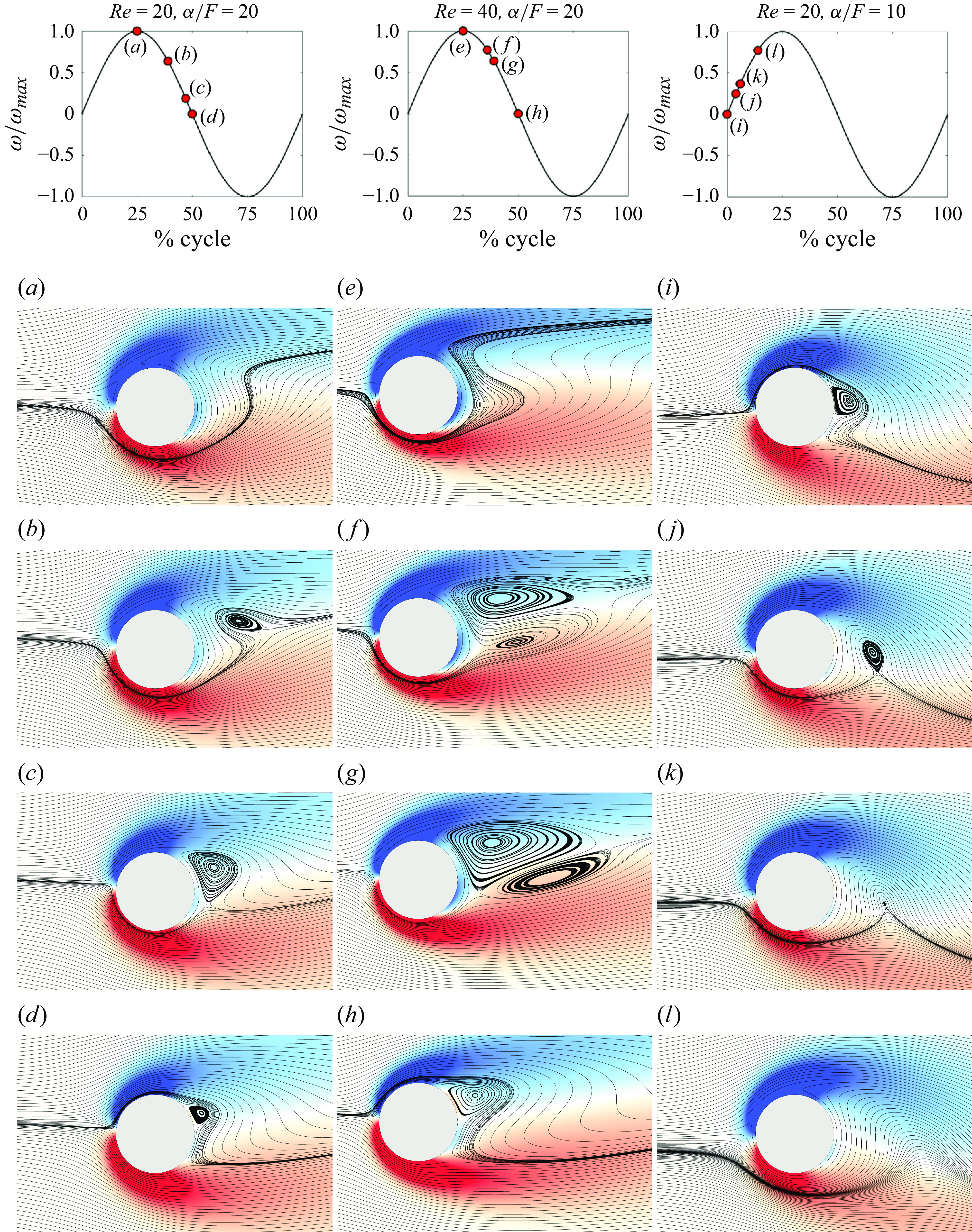
, and we compare our results with the results of Stojković et al. (Reference Stojković, Breuer and Durst2002) as shown in figure 1(a), where we plot the angle of the total force acting on the cylinder with respect to the streamwise direction,
$\alpha =2$
, and we compare our results with the results of Stojković et al. (Reference Stojković, Breuer and Durst2002) as shown in figure 1(a), where we plot the angle of the total force acting on the cylinder with respect to the streamwise direction,
 $\gamma = \tan^{-1}(C_L/C_D)$
, versus the rotation rate. For a fixed cylinder (
$\gamma = \tan^{-1}(C_L/C_D)$
, versus the rotation rate. For a fixed cylinder (
 $\alpha =0$
),
$\alpha =0$
),
 $\gamma =0$
, since the mean lift force is zero. The increase in
$\gamma =0$
, since the mean lift force is zero. The increase in
 $\gamma$
with the rotation rate that we have found in our results matches the trend observed by Stojković et al. (Reference Stojković, Breuer and Durst2002) for both Reynolds numbers,
$\gamma$
with the rotation rate that we have found in our results matches the trend observed by Stojković et al. (Reference Stojković, Breuer and Durst2002) for both Reynolds numbers,
 ${Re}=1$
and
${Re}=1$
and
 ${Re}=20$
. The streamlines for flow past a fixed cylinder are shown in figure 1(b) at
${Re}=20$
. The streamlines for flow past a fixed cylinder are shown in figure 1(b) at
 ${Re}=20$
where two Föppl vortices are observed, and in figure 1(c) where upon an imposed rotation of
${Re}=20$
where two Föppl vortices are observed, and in figure 1(c) where upon an imposed rotation of
 $\alpha =2$
, the flow symmetry in the wake is broken and the Föppl vortices disappear.
$\alpha =2$
, the flow symmetry in the wake is broken and the Föppl vortices disappear.
(a) Angle of the total force,
 $\gamma = \tan^{-1} C_L/C_D$
, versus the rotation rate for different Reynolds numbers, as well as the streamlines around (b) a fixed cylinder and (c) a cylinder with constant rotation at
$\gamma = \tan^{-1} C_L/C_D$
, versus the rotation rate for different Reynolds numbers, as well as the streamlines around (b) a fixed cylinder and (c) a cylinder with constant rotation at
 $\alpha =2$
, both at
$\alpha =2$
, both at
 ${Re}=20$
.
${Re}=20$
.

3. Suppressing Föppl vortices in the near wake
3.1. Increasing the rotation rate to suppress the Föppl vortices
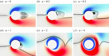
Snapshots of the wake with overlaid streamlines and vorticity plots for varying rotation rates at
 ${Re} = 20$
and
${Re} = 20$
and
 $\alpha / F = 20$
. The vorticity range is
$\alpha / F = 20$
. The vorticity range is
 $-25$
to 25 s
$-25$
to 25 s
 $^{-1}$
. These snapshots are captured when the cylinder is at the end of its CW rotation and is about to start rotating in the CCW direction, i.e. an instantaneous rotation rate of zero.
$^{-1}$
. These snapshots are captured when the cylinder is at the end of its CW rotation and is about to start rotating in the CCW direction, i.e. an instantaneous rotation rate of zero.
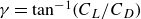
We first focus on the influence of the forced periodic rotation on the cylinder’s near wake and observe how these forced rotations influence the formation of the Föppl vortices. Snapshots of the near wake for increasing rotation rate are shown in figure 2 for rotation rates varying from
 $\alpha =0$
to
$\alpha =0$
to
 $\alpha =4$
, while keeping the Reynolds number and the maximum angular displacement constant at
$\alpha =4$
, while keeping the Reynolds number and the maximum angular displacement constant at
 ${Re}=20$
and
${Re}=20$
and
 $\alpha /F=20$
, respectively. These snapshots correspond to the moment when the cylinder has stopped rotating in the clockwise (CW) direction and is about to start rotating in the CCW direction, i.e. at an instantaneous angular velocity of zero. For
$\alpha /F=20$
, respectively. These snapshots correspond to the moment when the cylinder has stopped rotating in the clockwise (CW) direction and is about to start rotating in the CCW direction, i.e. at an instantaneous angular velocity of zero. For
 $\alpha =0$
, symmetric Föppl vortices are observed in the near wake as expected (figure 2
a). Slightest rotation breaks the flow symmetry in the wake and the Föppl vortices are suppressed over a major portion of the rotation period. The Föppl vortices appear only momentarily when the instantaneous angular velocity is zero. For
$\alpha =0$
, symmetric Föppl vortices are observed in the near wake as expected (figure 2
a). Slightest rotation breaks the flow symmetry in the wake and the Föppl vortices are suppressed over a major portion of the rotation period. The Föppl vortices appear only momentarily when the instantaneous angular velocity is zero. For
 $\alpha =0.3$
, the bottom Föppl vortex does not exist at this instant of time, even in the form of a very small vortex, and the top vortex is reduced in size since the flow is deflected more by the larger rotation rates (figure 2
b). The size of the momentarily observed upper Föppl vortex reduces with increasing rotation rate to
$\alpha =0.3$
, the bottom Föppl vortex does not exist at this instant of time, even in the form of a very small vortex, and the top vortex is reduced in size since the flow is deflected more by the larger rotation rates (figure 2
b). The size of the momentarily observed upper Föppl vortex reduces with increasing rotation rate to
 $\alpha =0.5$
. For
$\alpha =0.5$
. For
 $\alpha =1$
(figure 2
d), the upper Föppl vortex becomes diminishingly small. The Föppl vortices disappear completely for rotation rates larger than
$\alpha =1$
(figure 2
d), the upper Föppl vortex becomes diminishingly small. The Föppl vortices disappear completely for rotation rates larger than
 $\alpha =1$
, as shown for sample cases of
$\alpha =1$
, as shown for sample cases of
 $\alpha =2$
and
$\alpha =2$
and
 $\alpha =4$
in figure 2(e,f).
$\alpha =4$
in figure 2(e,f).
3.2. Decreasing
 $\alpha /F$
to suppress the Föppl vortices
$\alpha /F$
to suppress the Föppl vortices

Streamline plots around a cylinder periodically rotating at a rotation rate of
 $\alpha =0.5$
, a constant Reynolds number of
$\alpha =0.5$
, a constant Reynolds number of
 ${Re}=40$
and for three different values of
${Re}=40$
and for three different values of
 $\alpha /F$
. These snapshots are captured at the end of the CW rotation.
$\alpha /F$
. These snapshots are captured at the end of the CW rotation.

For larger Reynolds numbers within the subcritical range, the size of the Föppl vortices increases. Earlier, we demonstrated that these larger Föppl vortices can be suppressed completely by increasing the rotation rate while keeping
 $\alpha /F$
constant. Here, we show that for a constant rotation rate,
$\alpha /F$
constant. Here, we show that for a constant rotation rate,
 $\alpha$
, we can suppress the Föppl vortices by decreasing
$\alpha$
, we can suppress the Föppl vortices by decreasing
 $\alpha / F$
(i.e. increasing the forcing frequency). Figure 3 shows the near wake of the cylinder at
$\alpha / F$
(i.e. increasing the forcing frequency). Figure 3 shows the near wake of the cylinder at
 ${Re}=40$
as a sample case, as the cylinder is forced to rotate at three distinct dimensionless rotation frequencies of
${Re}=40$
as a sample case, as the cylinder is forced to rotate at three distinct dimensionless rotation frequencies of
 $\alpha /F=20$
, 10 and 6.7. A Föppl vortex is observed in the re-circulation region for
$\alpha /F=20$
, 10 and 6.7. A Föppl vortex is observed in the re-circulation region for
 $\alpha /F=20$
(figure 3
a). When
$\alpha /F=20$
(figure 3
a). When
 $\alpha /F$
is decreased to
$\alpha /F$
is decreased to
 $\alpha /F=10$
by increasing the forcing frequency,
$\alpha /F=10$
by increasing the forcing frequency,
 $f$
, the bottom Föppl vortex becomes smaller, but still a large vortex is formed on the upper side of the cylinder, which travels downstream before it dissipates (figure 3
b). Both of these vortices disappear from the near wake when
$f$
, the bottom Föppl vortex becomes smaller, but still a large vortex is formed on the upper side of the cylinder, which travels downstream before it dissipates (figure 3
b). Both of these vortices disappear from the near wake when
 $\alpha /F$
is further decreased to
$\alpha /F$
is further decreased to
 $\alpha /F=6.7$
(figure 3
c).
$\alpha /F=6.7$
(figure 3
c).
3.3. Mechanisms of vortex formation and dissipation in the near wake
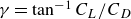
Overlaid snapshots of streamlines and vorticity for (a–d)
 ${Re}=20$
and
${Re}=20$
and
 $\alpha /F = 20$
; (e–h)
$\alpha /F = 20$
; (e–h)
 ${Re}=40$
and
${Re}=40$
and
 $\alpha /F = 20$
; and (i–l)
$\alpha /F = 20$
; and (i–l)
 ${Re}=20$
and
${Re}=20$
and
 $\alpha /F = 10$
, at different instances over one cycle of rotation. The rotation rate for all these cases is
$\alpha /F = 10$
, at different instances over one cycle of rotation. The rotation rate for all these cases is
 $\alpha = 0.5$
. The vorticity range is
$\alpha = 0.5$
. The vorticity range is
 $-25$
to
$-25$
to
 $25$
s
$25$
s
 $^{-1}$
. In each column, the cycle of periodic rotation is shown in the first row by plotting the normalised angular velocity during the cycle. The markers on the plot indicate the instances when the snapshots are taken.
$^{-1}$
. In each column, the cycle of periodic rotation is shown in the first row by plotting the normalised angular velocity during the cycle. The markers on the plot indicate the instances when the snapshots are taken.
In general, we have observed three mechanisms for the formation and dissipation of vortices in the near wake when the cylinder is forced to rotate periodically. Figure 4 shows snapshots that correspond to samples for these three mechanisms.
The snapshots in figure 4(a–d) correspond to a case with
 ${Re}=20$
,
${Re}=20$
,
 $\alpha /F = 20$
and
$\alpha /F = 20$
and
 $\alpha =0.5$
. Figure 4(a) corresponds to an instance when the cylinder reaches its maximum rotation rate in the CCW direction. Moving from panels (a) to (b), the rotation rate is reduced, while the cylinder keeps rotating in the CCW direction. As the cylinder slows down, the influence of cylinder rotation remains localised in space, and the streamlines far from the cylinder straighten out and follow the incoming flow. The streamlines close to the cylinder curve due to the influence of rotation, and as a result, a vortex originates filling the gap between the curved streamlines and the straight streamlines (figure 4
b). The formation of this vortex differs from the typical Föppl vortex formation in the case of a fixed cylinder as this vortex does not form exactly behind the cylinder. As the cylinder’s rotation slows down further (moving from the panels bto c), this vortex grows in size and moves upstream, as the reduced rotation rate of the cylinder does not influence the streamlines enough to curve and therefore more streamlines straighten out causing the re-circulation region to become wider. As the cylinder reaches zero angular velocity (panel d), the vortex reaches the cylinder and its size reduces, since the CCW rotation of the cylinder that was feeding the vortex earlier has now become zero and the dominant direction of curving of the streamlines has changed. This vortex disappears completely as the cylinder starts rotating in the CW direction.
$\alpha =0.5$
. Figure 4(a) corresponds to an instance when the cylinder reaches its maximum rotation rate in the CCW direction. Moving from panels (a) to (b), the rotation rate is reduced, while the cylinder keeps rotating in the CCW direction. As the cylinder slows down, the influence of cylinder rotation remains localised in space, and the streamlines far from the cylinder straighten out and follow the incoming flow. The streamlines close to the cylinder curve due to the influence of rotation, and as a result, a vortex originates filling the gap between the curved streamlines and the straight streamlines (figure 4
b). The formation of this vortex differs from the typical Föppl vortex formation in the case of a fixed cylinder as this vortex does not form exactly behind the cylinder. As the cylinder’s rotation slows down further (moving from the panels bto c), this vortex grows in size and moves upstream, as the reduced rotation rate of the cylinder does not influence the streamlines enough to curve and therefore more streamlines straighten out causing the re-circulation region to become wider. As the cylinder reaches zero angular velocity (panel d), the vortex reaches the cylinder and its size reduces, since the CCW rotation of the cylinder that was feeding the vortex earlier has now become zero and the dominant direction of curving of the streamlines has changed. This vortex disappears completely as the cylinder starts rotating in the CW direction.
For the same rotation rate and frequency, but at a higher Reynolds number of
 ${Re}\,{=}\,40$
, shown in figure 4(e–h), the streamlines that pass the lower side of the cylinder go further downstream before turning and following the cylinder’s CCW rotation (figure 4
e). This creates S-shaped streamlines near the cylinder and, as the rotation slows down, the re-circulation zone becomes longer and the S-shape becomes flatter. In addition to the previously observed CW vortex at the top, we now observe a weak CCW vortex underneath the CW vortex (figure 4
f). Following a similar phenomenon discussed in the previous case for
${Re}\,{=}\,40$
, shown in figure 4(e–h), the streamlines that pass the lower side of the cylinder go further downstream before turning and following the cylinder’s CCW rotation (figure 4
e). This creates S-shaped streamlines near the cylinder and, as the rotation slows down, the re-circulation zone becomes longer and the S-shape becomes flatter. In addition to the previously observed CW vortex at the top, we now observe a weak CCW vortex underneath the CW vortex (figure 4
f). Following a similar phenomenon discussed in the previous case for
 ${Re}=20$
, the top vortex grows and moves upstream, causing the bottom vortex to move downstream as the cylinder rotation further slows down (figure 4
g). As the cylinder rotation reaches zero angular velocity, the top vortex reaches the cylinder and reduces in size (figure 4
h), and the bottom vortex moves downstream and is shed.
${Re}=20$
, the top vortex grows and moves upstream, causing the bottom vortex to move downstream as the cylinder rotation further slows down (figure 4
g). As the cylinder rotation reaches zero angular velocity, the top vortex reaches the cylinder and reduces in size (figure 4
h), and the bottom vortex moves downstream and is shed.
In figure 4(i–l), we consider the case of
 ${Re}=20$
and
${Re}=20$
and
 $\alpha =0.5$
, at a dimensionless rotation frequency of
$\alpha =0.5$
, at a dimensionless rotation frequency of
 $\alpha /F = 10$
. In this case, we do not observe an upstream-moving vortex when the cylinder rotation slows down, since the smaller
$\alpha /F = 10$
. In this case, we do not observe an upstream-moving vortex when the cylinder rotation slows down, since the smaller
 $\alpha /F$
(larger frequency) does not provide enough time for the vortex to form and move upstream. Instead, we observe a vortex in the re-circulation region very close to the cylinder as the cylinder switches the direction of rotation from CW to CCW (figure 4
i). As the cylinder starts its CCW rotation, the streamlines move along with the cylinder, detaching the vortex and forcing it to move downstream (figure 4
j). The vortex then disappears as the angular velocity is increased (figure 4
k,l).
$\alpha /F$
(larger frequency) does not provide enough time for the vortex to form and move upstream. Instead, we observe a vortex in the re-circulation region very close to the cylinder as the cylinder switches the direction of rotation from CW to CCW (figure 4
i). As the cylinder starts its CCW rotation, the streamlines move along with the cylinder, detaching the vortex and forcing it to move downstream (figure 4
j). The vortex then disappears as the angular velocity is increased (figure 4
k,l).
4. Inducing vortex shedding in the far wake
We now focus on the far wake of the cylinder to discuss how vortices are formed in the far wake as we impose a periodic rotation at a constant rotation rate or a constant
 $\alpha /F$
.
$\alpha /F$
.
4.1. Inducing vortices by varying
$\alpha /F$

Vorticity contours for varying
 $\alpha /F$
at three different rotation rates, (a)
$\alpha /F$
at three different rotation rates, (a)
 $\alpha =1$
, (b)
$\alpha =1$
, (b)
 $\alpha =1.5$
and (c)
$\alpha =1.5$
and (c)
 $\alpha =2$
. For all these cases,
$\alpha =2$
. For all these cases,
 ${Re}=20$
. In each column,
${Re}=20$
. In each column,
 $\alpha /F$
decreases from top to bottom. The vorticity ranges from
$\alpha /F$
decreases from top to bottom. The vorticity ranges from
 $-5$
to 5 s
$-5$
to 5 s
 $^{-1}$
. These snapshots are captured at the end of the CW rotation.
$^{-1}$
. These snapshots are captured at the end of the CW rotation.

First, we consider the cases where we keep the Reynolds number constant at
 ${Re}=20$
and impose a rotation at a constant rotation rate,
${Re}=20$
and impose a rotation at a constant rotation rate,
 $\alpha =1$
, 1.5 or 2, and decreasing
$\alpha =1$
, 1.5 or 2, and decreasing
 $\alpha /F$
, i.e. increasing rotation frequency (top to bottom in figure 5). To decrease
$\alpha /F$
, i.e. increasing rotation frequency (top to bottom in figure 5). To decrease
 $\alpha /F$
, the dimensional frequency
$\alpha /F$
, the dimensional frequency
 $f$
is increased while maintaining a constant angular velocity,
$f$
is increased while maintaining a constant angular velocity,
 $\omega$
. Then, as the frequency is increased, the maximum angle of rotation is decreased. For the largest
$\omega$
. Then, as the frequency is increased, the maximum angle of rotation is decreased. For the largest
 $\alpha /F$
, as shown in figure 5 (first row),
$\alpha /F$
, as shown in figure 5 (first row),
 $\alpha /F=200$
, the shear layers extend downstream and they are minimally disrupted by the forced rotation as the dimensional frequency is very small. Weak vortex shedding is observed at
$\alpha /F=200$
, the shear layers extend downstream and they are minimally disrupted by the forced rotation as the dimensional frequency is very small. Weak vortex shedding is observed at
 $\alpha =2$
. With decreasing
$\alpha =2$
. With decreasing
 $\alpha /F$
(increasing dimensional frequency), these long shear layers start interacting with each other due to imposed periodic rotation and vortices are shed in the wake. Decreasing
$\alpha /F$
(increasing dimensional frequency), these long shear layers start interacting with each other due to imposed periodic rotation and vortices are shed in the wake. Decreasing
 $\alpha /F$
at a constant angular velocity,
$\alpha /F$
at a constant angular velocity,
 $\omega$
, results in a reduction in the maximum angular displacement. Consequently, the size of the vortices that are shed in the wake decreases (moving from top to bottom in figure 5). The vortex-shedding frequency follows the rotation frequency,
$\omega$
, results in a reduction in the maximum angular displacement. Consequently, the size of the vortices that are shed in the wake decreases (moving from top to bottom in figure 5). The vortex-shedding frequency follows the rotation frequency,
 $f$
. For smaller values of
$f$
. For smaller values of
 $\alpha /F$
(e.g.
$\alpha /F$
(e.g.
 $\alpha /F=13$
and
$\alpha /F=13$
and
 $\alpha /F=20$
for
$\alpha /F=20$
for
 $\alpha =1$
and
$\alpha =1$
and
 $\alpha =1.5$
, respectively), the shed vortices become much smaller. For the lowest values of
$\alpha =1.5$
, respectively), the shed vortices become much smaller. For the lowest values of
 $\alpha /F$
shown in the figure (i.e. the highest forcing frequencies tested here), the periodic rotation merely perturbs the shear layers and the vortex shedding ceases, since the maximum angle of rotation becomes extremely small. Therefore, it becomes clear that whether or not shedding is observed in the wake depends on the combination of the rotation rate and rotation frequency. This range is highlighted in the figure.
$\alpha /F$
shown in the figure (i.e. the highest forcing frequencies tested here), the periodic rotation merely perturbs the shear layers and the vortex shedding ceases, since the maximum angle of rotation becomes extremely small. Therefore, it becomes clear that whether or not shedding is observed in the wake depends on the combination of the rotation rate and rotation frequency. This range is highlighted in the figure.
4.2. Inducing vortices by varying the rotation rate
Vortices can also be induced by varying the rotation rate at a constant
 $\alpha /F$
. In figure 6, vorticity plots are shown for increasing rotation rates at
$\alpha /F$
. In figure 6, vorticity plots are shown for increasing rotation rates at
 $\alpha /F=40$
. Inducing vortices in the wake at subcritical Reynolds number does not occur for very small rotation rates, which is evident from figure 6(a). By increasing the rotation rate from
$\alpha /F=40$
. Inducing vortices in the wake at subcritical Reynolds number does not occur for very small rotation rates, which is evident from figure 6(a). By increasing the rotation rate from
 $\alpha =0.5$
to
$\alpha =0.5$
to
 $\alpha =1$
, vortex shedding is observed in the wake. The vortex shedding becomes prominent with further increase in the rotation rate (e.g.
$\alpha =1$
, vortex shedding is observed in the wake. The vortex shedding becomes prominent with further increase in the rotation rate (e.g.
 $\alpha =1.5$
and
$\alpha =1.5$
and
 $\alpha =2$
). It is important to note that the rotation rate is increased while keeping the Reynolds number and
$\alpha =2$
). It is important to note that the rotation rate is increased while keeping the Reynolds number and
 $\alpha /F$
constant. The dimensional frequency must also increase to maintain constant
$\alpha /F$
constant. The dimensional frequency must also increase to maintain constant
 $\alpha /F$
with increasing rotation rate,
$\alpha /F$
with increasing rotation rate,
 $\alpha$
. Therefore, the vortex-shedding frequency increases with increasing rotation rate. At large values of rotation rate,
$\alpha$
. Therefore, the vortex-shedding frequency increases with increasing rotation rate. At large values of rotation rate,
 $\alpha =3$
and
$\alpha =3$
and
 $\alpha =4$
, the shed vortices are much smaller in size and they coalesce in the far wake as seen in figures 6(e) and 6(f). Increasing the rotation rate further will cause the vortex shedding to cease and only the perturbations in the shear layers will be observed. The window where vortex shedding is observed moves to larger values of rotation rate,
$\alpha =4$
, the shed vortices are much smaller in size and they coalesce in the far wake as seen in figures 6(e) and 6(f). Increasing the rotation rate further will cause the vortex shedding to cease and only the perturbations in the shear layers will be observed. The window where vortex shedding is observed moves to larger values of rotation rate,
 $\alpha$
, with increasing
$\alpha$
, with increasing
 $\alpha /F$
, as depicted in figure 5. It becomes clear from these results that one should control both
$\alpha /F$
, as depicted in figure 5. It becomes clear from these results that one should control both
 $\alpha$
and
$\alpha$
and
 $\alpha /F$
to induce vortex shedding with a desired strength, a desired size and a desired shedding frequency within the subcritical Reynolds number range.
$\alpha /F$
to induce vortex shedding with a desired strength, a desired size and a desired shedding frequency within the subcritical Reynolds number range.
Vorticity plots for varying rotation rates,
 $\alpha$
, at
$\alpha$
, at
 $\alpha /F=40$
. The Reynolds number is fixed at
$\alpha /F=40$
. The Reynolds number is fixed at
 ${Re}=20$
for all cases. The colourbar range is –5 to 5
${Re}=20$
for all cases. The colourbar range is –5 to 5
 ${\rm s}^{-1}$
.
${\rm s}^{-1}$
.

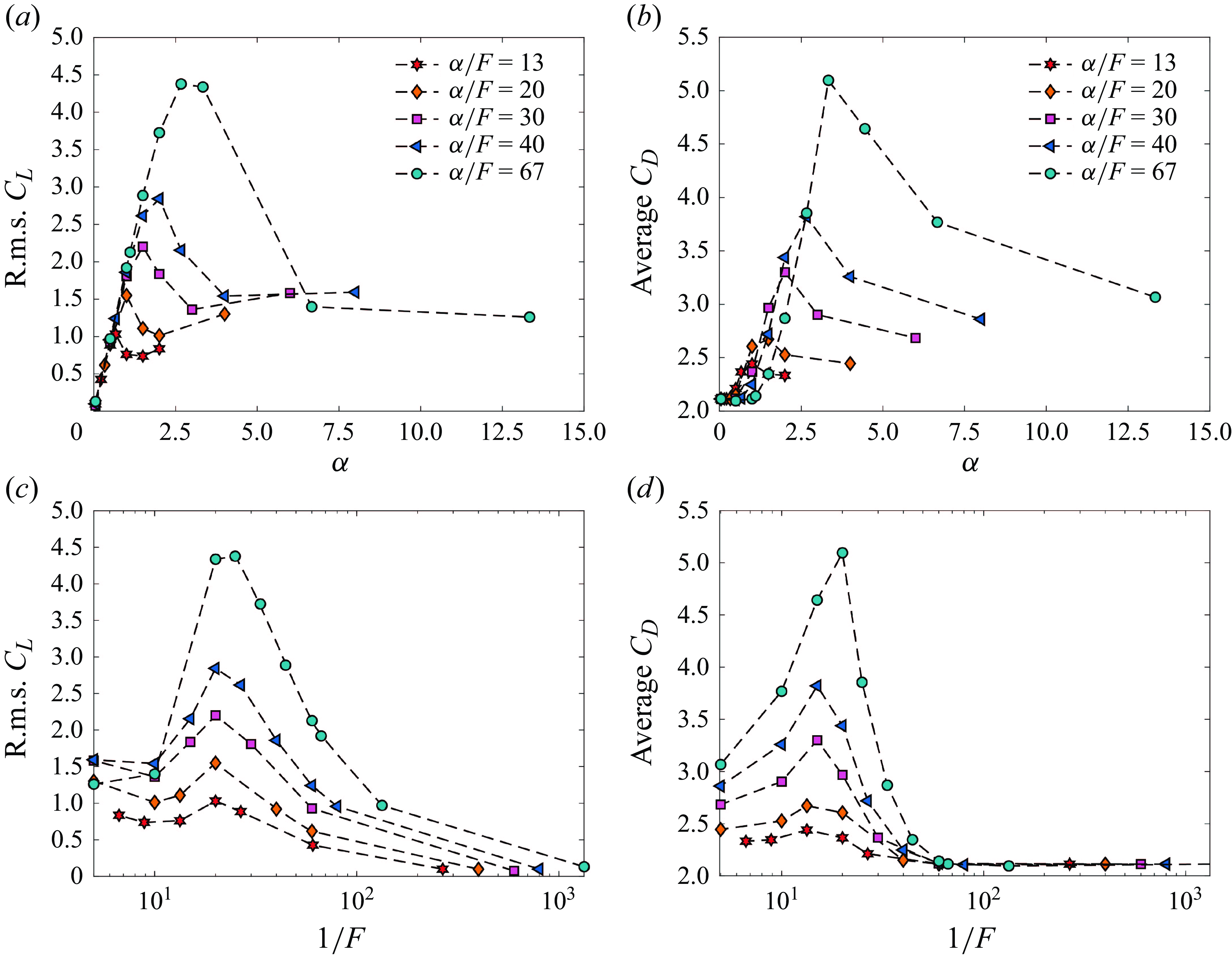
Root-mean-square lift coefficient versus (a) rotation rate,
 $\alpha$
, and (c)
$\alpha$
, and (c)
 $1/F$
for varying
$1/F$
for varying
 $\alpha /F$
. The average drag coefficient versus (b) rotation rate,
$\alpha /F$
. The average drag coefficient versus (b) rotation rate,
 $\alpha$
, and (d)
$\alpha$
, and (d)
 $1/F$
for varying
$1/F$
for varying
 $\alpha /F$
. The Reynolds number is
$\alpha /F$
. The Reynolds number is
 ${Re}=20$
for all cases.
${Re}=20$
for all cases.
4.3. Lift and drag forces imposed on the cylinder
Time-averaged pressure distribution on a cylinder shown as a coefficient of pressure (
 $C_p$
) versus the angle (
$C_p$
) versus the angle (
 $\theta$
) for
$\theta$
) for
 $\alpha /F=40$
. The angle
$\alpha /F=40$
. The angle
 $\theta =0$
is defined at the upstream side of the cylinder, where the incoming flow first encounters the cylinder surface. The angle
$\theta =0$
is defined at the upstream side of the cylinder, where the incoming flow first encounters the cylinder surface. The angle
 $\theta$
increases in the clockwise direction around the cylinder. The Reynolds number is
$\theta$
increases in the clockwise direction around the cylinder. The Reynolds number is
 ${Re}=20$
for all cases.
${Re}=20$
for all cases.

As vortices are formed in the wake of the cylinder forced to rotate periodically, fluctuating lift forces act on the cylinder. In figure 7(a), the r.m.s. (root mean square) of the lift coefficient is plotted against the rotation rate,
 $\alpha$
, for different forcing frequencies, represented as
$\alpha$
, for different forcing frequencies, represented as
 $\alpha /F$
. For the highest rotation frequency,
$\alpha /F$
. For the highest rotation frequency,
 $\alpha /F=13$
, the r.m.s. lift increases when the rotation rate is increased to
$\alpha /F=13$
, the r.m.s. lift increases when the rotation rate is increased to
 $\alpha =0.5$
, as vortices start to form. It peaks at
$\alpha =0.5$
, as vortices start to form. It peaks at
 $\alpha =0.67$
and then decreases slightly with a further increase in the rotation rate. For
$\alpha =0.67$
and then decreases slightly with a further increase in the rotation rate. For
 $\alpha \gt 0.5$
, the r.m.s. lift increases with increasing
$\alpha \gt 0.5$
, the r.m.s. lift increases with increasing
 $\alpha /F$
due to the larger vortices that are shed at higher values of
$\alpha /F$
due to the larger vortices that are shed at higher values of
 $\alpha /F$
(as seen in figure 5). With increasing
$\alpha /F$
(as seen in figure 5). With increasing
 $\alpha /F$
, the r.m.s. lift peaks at a larger value of
$\alpha /F$
, the r.m.s. lift peaks at a larger value of
 $\alpha$
. These maxima occur at
$\alpha$
. These maxima occur at
 $\alpha =1$
,
$\alpha =1$
,
 $1.5$
,
$1.5$
,
 $2$
and
$2$
and
 $2.67$
for
$2.67$
for
 $\alpha /F=20$
,
$\alpha /F=20$
,
 $30$
,
$30$
,
 $40$
and
$40$
and
 $67$
, respectively. This trend is observed because the vortex shedding occurs at a larger value of rotation rate,
$67$
, respectively. This trend is observed because the vortex shedding occurs at a larger value of rotation rate,
 $\alpha$
, with increasing
$\alpha$
, with increasing
 $\alpha /F$
, as shown previously in figure 5. For all values of
$\alpha /F$
, as shown previously in figure 5. For all values of
 $\alpha /F$
, the drop in the r.m.s. lift that is observed for larger values of rotation rate corresponds to the weaker vortex shedding caused by the increased dimensional frequency at larger values of rotation rate.
$\alpha /F$
, the drop in the r.m.s. lift that is observed for larger values of rotation rate corresponds to the weaker vortex shedding caused by the increased dimensional frequency at larger values of rotation rate.
The average drag coefficient is plotted against
 $\alpha$
for varying
$\alpha$
for varying
 $\alpha /F$
in figure 7(b). A trend similar to that observed in the plot of the r.m.s.
$\alpha /F$
in figure 7(b). A trend similar to that observed in the plot of the r.m.s.
 $C_L$
is observed here. At a constant
$C_L$
is observed here. At a constant
 $\alpha$
, the average drag coefficient increases with increasing
$\alpha$
, the average drag coefficient increases with increasing
 $\alpha /F$
. For a constant
$\alpha /F$
. For a constant
 $\alpha /F$
, the average
$\alpha /F$
, the average
 $C_D$
increases with increasing
$C_D$
increases with increasing
 $\alpha$
, reaches a peak and decreases with further increase in the rotation rate. This behaviour can be understood by plotting the pressure distribution on the cylinder for varying rotation rates at a constant
$\alpha$
, reaches a peak and decreases with further increase in the rotation rate. This behaviour can be understood by plotting the pressure distribution on the cylinder for varying rotation rates at a constant
 $\alpha /F$
. In figure 8, the coefficient of pressure,
$\alpha /F$
. In figure 8, the coefficient of pressure,
 $C_p$
, is plotted against the angle,
$C_p$
, is plotted against the angle,
 $\theta$
, for a sample case of
$\theta$
, for a sample case of
 $\alpha /F=40$
. The coefficient of pressure is time-averaged, since the cylinder is rotating periodically. The area over the
$\alpha /F=40$
. The coefficient of pressure is time-averaged, since the cylinder is rotating periodically. The area over the
 $C_p$
curve in figure 8 quantifies the pressure drag component of the overall drag coefficient,
$C_p$
curve in figure 8 quantifies the pressure drag component of the overall drag coefficient,
 $C_D$
. For
$C_D$
. For
 $\alpha =0.66$
, two separation points are observed (recognised by the change in sign of the slope of the
$\alpha =0.66$
, two separation points are observed (recognised by the change in sign of the slope of the
 $C_p$
curve) and the area over the
$C_p$
curve) and the area over the
 $C_p$
curve is the smallest. This case corresponds to the smallest average
$C_p$
curve is the smallest. This case corresponds to the smallest average
 $C_D$
among all four rotation rates shown in figure 8. With increasing the rotation rate to
$C_D$
among all four rotation rates shown in figure 8. With increasing the rotation rate to
 $\alpha =2$
, the angle between the two separation points decreases. At
$\alpha =2$
, the angle between the two separation points decreases. At
 $\alpha =2.66$
, flow separation does not occur as both separation points merge and the area over the
$\alpha =2.66$
, flow separation does not occur as both separation points merge and the area over the
 $C_p$
curve is the largest. Therefore, the average
$C_p$
curve is the largest. Therefore, the average
 $C_D$
peaks at
$C_D$
peaks at
 $\alpha =2.66$
. With increasing the rotation rate to
$\alpha =2.66$
. With increasing the rotation rate to
 $\alpha =4$
, two separation points reappear because the cylinder rotates at a larger angular velocity in a clockwise or counterclockwise direction for a shorter period of time to maintain constant
$\alpha =4$
, two separation points reappear because the cylinder rotates at a larger angular velocity in a clockwise or counterclockwise direction for a shorter period of time to maintain constant
 $\alpha /F$
. Therefore, the area over the
$\alpha /F$
. Therefore, the area over the
 $C_p$
curve for
$C_p$
curve for
 $\alpha =4$
is smaller compared with for
$\alpha =4$
is smaller compared with for
 $\alpha =2.66$
, signifying the drop in the average
$\alpha =2.66$
, signifying the drop in the average
 $C_D$
after peaking at
$C_D$
after peaking at
 $\alpha =2.66$
.
$\alpha =2.66$
.
In the plots in figure 7(a,b), we observe that the maximum fluctuating lift and mean drag occur at progressively larger values of
 $\alpha$
, for increasing
$\alpha$
, for increasing
 $\alpha /F$
. If, instead of plotting these values versus
$\alpha /F$
. If, instead of plotting these values versus
 $\alpha$
, we plot them versus
$\alpha$
, we plot them versus
 $\alpha /F$
divided by
$\alpha /F$
divided by
 $\alpha$
, i.e.
$\alpha$
, i.e.
 $1/F$
(figures 7
c and 7
d), then the peak r.m.s.
$1/F$
(figures 7
c and 7
d), then the peak r.m.s.
 $C_L$
occurs at a constant
$C_L$
occurs at a constant
 $1/F = 20$
for all
$1/F = 20$
for all
 $\alpha /F$
cases and the peak of the mean drag coefficients occurs at a value between
$\alpha /F$
cases and the peak of the mean drag coefficients occurs at a value between
 $1/F=15$
and
$1/F=15$
and
 $1/F=20$
.
$1/F=20$
.
This new variable
 $1/F$
can also be written as
$1/F$
can also be written as
 \begin{equation} \frac {1}{F} = \frac {2U}{fD} = U^* .\end{equation}
The variable
 $2U/(fD)$
is very similar to the reduced velocity,
$2U/(fD)$
is very similar to the reduced velocity,
 $U^*$
, commonly found in the literature of flow-induced vibrations (Williamson & Govardhan Reference Williamson and Govardhan2004; Patel Reference Patel2024). As the incoming velocity,
$U^*$
, commonly found in the literature of flow-induced vibrations (Williamson & Govardhan Reference Williamson and Govardhan2004; Patel Reference Patel2024). As the incoming velocity,
 $U$
, and the cylinder diameter,
$U$
, and the cylinder diameter,
 $D$
, remain constant for the cases shown in figure 7, the variable
$D$
, remain constant for the cases shown in figure 7, the variable
 $U^*$
is inversely proportional to the frequency of the rotational oscillations,
$U^*$
is inversely proportional to the frequency of the rotational oscillations,
 $f$
.
$f$
.
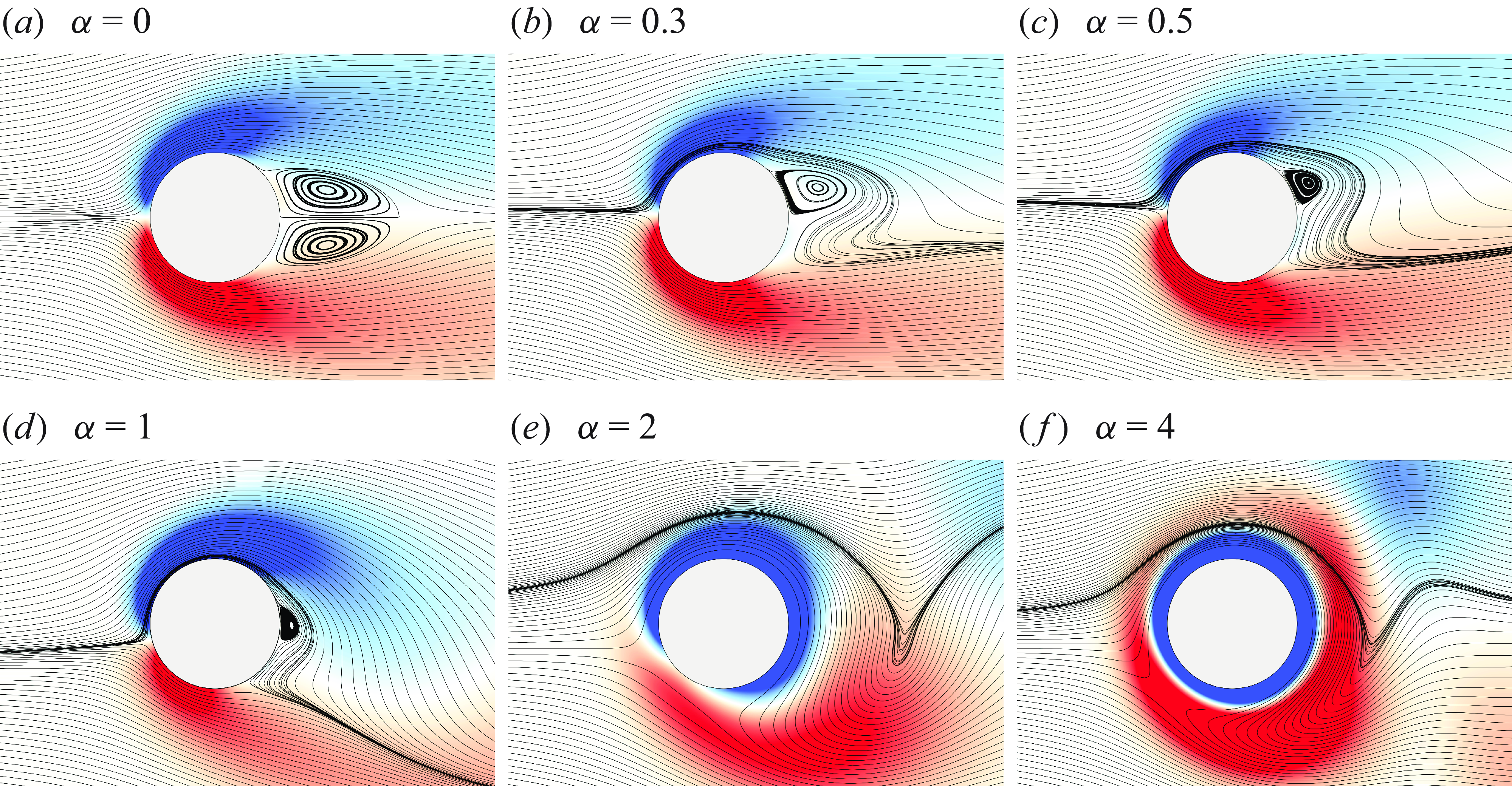
(i) Fluctuating lift force and (ii) peak frequency of the lift force time history normalised by the forcing frequency versus
 $1/F$
. Three zones with three different wake patterns are observed in the wake of a cylinder forced to rotate periodically (highlighted in the plots). Samples of the vorticity contours are shown in the lower panels: for (a–d)
$1/F$
. Three zones with three different wake patterns are observed in the wake of a cylinder forced to rotate periodically (highlighted in the plots). Samples of the vorticity contours are shown in the lower panels: for (a–d)
 $1/F=10$
; (e–h)
$1/F=10$
; (e–h)
 $1/F = 20$
;, and (i–l)
$1/F = 20$
;, and (i–l)
 $1/F = 60$
for varying
$1/F = 60$
for varying
 $\alpha /F$
. The Reynolds number is fixed at
$\alpha /F$
. The Reynolds number is fixed at
 ${Re}=20$
for all cases. The colourbar range is from −5 to 5
${Re}=20$
for all cases. The colourbar range is from −5 to 5
 ${\rm s}^{-1}$
.
${\rm s}^{-1}$
.
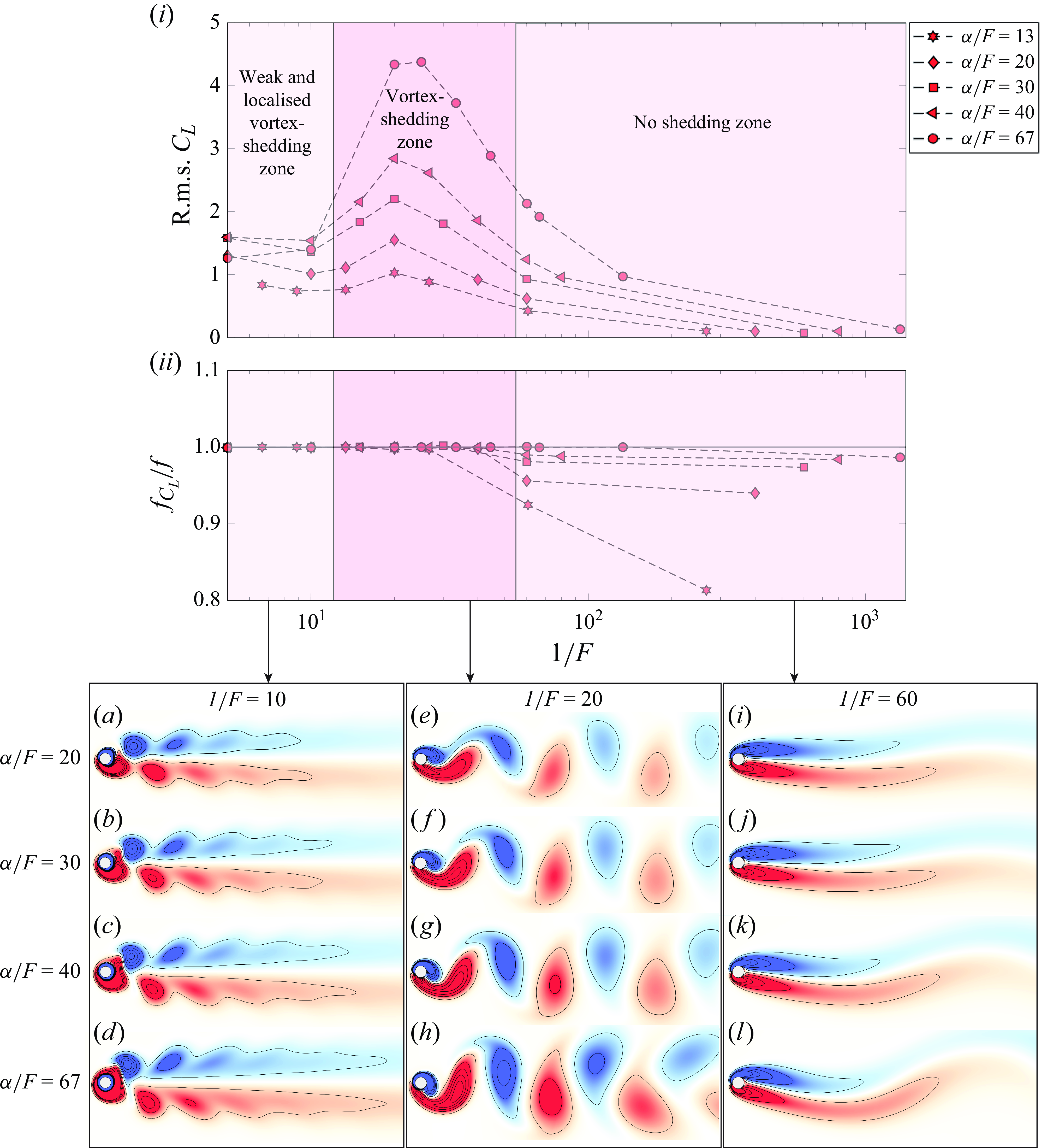
In figure 9(a–l), vorticity contours are plotted over a range of
 $1/F$
values and for various
$1/F$
values and for various
 $\alpha /F$
values. The Reynolds number is kept constant for all cases at
$\alpha /F$
values. The Reynolds number is kept constant for all cases at
 ${Re}=20$
. Based on the observed vorticity patterns, we can categorise the observed wakes into three distinct zones. For lower values of
${Re}=20$
. Based on the observed vorticity patterns, we can categorise the observed wakes into three distinct zones. For lower values of
 $1/F$
, the vortices are weak and observed only in the close proximity of the cylinder. Due to the high frequency of cylinder rotation within this range, vortices are separated quickly from the cylinder before being fully formed, merely perturbing the shear layers. Such vorticity patterns are observed for any combination of
$1/F$
, the vortices are weak and observed only in the close proximity of the cylinder. Due to the high frequency of cylinder rotation within this range, vortices are separated quickly from the cylinder before being fully formed, merely perturbing the shear layers. Such vorticity patterns are observed for any combination of
 $\alpha$
and
$\alpha$
and
 $\alpha /F$
values leading to small values of
$\alpha /F$
values leading to small values of
 $1/F$
(approximately less than 12). This region is highlighted in figure 9(i) as the weak and localised vortex-shedding zone. At larger values of
$1/F$
(approximately less than 12). This region is highlighted in figure 9(i) as the weak and localised vortex-shedding zone. At larger values of
 $1/F$
, where the frequency of rotation is reduced, we observe a pattern similar to the von Kármán vortex street over a range of
$1/F$
, where the frequency of rotation is reduced, we observe a pattern similar to the von Kármán vortex street over a range of
 $1/F$
values. This region is highlighted as the vortex-shedding zone in figure 9(i). Vortex shedding is observed for any combination of
$1/F$
values. This region is highlighted as the vortex-shedding zone in figure 9(i). Vortex shedding is observed for any combination of
 $\alpha$
and
$\alpha$
and
 $\alpha /F$
values leading to moderate values of
$\alpha /F$
values leading to moderate values of
 $1/F$
(approximately in the range of
$1/F$
(approximately in the range of
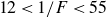 $12\lt 1/F\lt 55$
). At higher values of
$12\lt 1/F\lt 55$
). At higher values of
 $1/F$
(approximately greater than 55), i.e. lower rotation frequencies, vortex shedding ceases completely. In this range, the shear layers stretch far downstream and vortices are not formed in the near wake. This region is highlighted as the no shedding zone in figure 9(i). Clearly, the range of high-amplitude fluctuating lift forces corresponds to the vortex-shedding zone where fully formed vortices are shed in the near wake of the cylinder due to the forced rotation and exert relatively large fluctuating lift forces on the structure. The forced rotation causes the fluctuations in the shear layers and, in some cases, the formation of vortices. The frequency of the fluctuations in the lift force caused by the periodic rotation is calculated through the FFT (fast Fourier transform) of the lift force time history. This frequency is indicated by
$1/F$
(approximately greater than 55), i.e. lower rotation frequencies, vortex shedding ceases completely. In this range, the shear layers stretch far downstream and vortices are not formed in the near wake. This region is highlighted as the no shedding zone in figure 9(i). Clearly, the range of high-amplitude fluctuating lift forces corresponds to the vortex-shedding zone where fully formed vortices are shed in the near wake of the cylinder due to the forced rotation and exert relatively large fluctuating lift forces on the structure. The forced rotation causes the fluctuations in the shear layers and, in some cases, the formation of vortices. The frequency of the fluctuations in the lift force caused by the periodic rotation is calculated through the FFT (fast Fourier transform) of the lift force time history. This frequency is indicated by
 $f_{C_L}$
. The sustained global instability is caused by the lock-in between the frequency of periodic rotation and
$f_{C_L}$
. The sustained global instability is caused by the lock-in between the frequency of periodic rotation and
 $f_{C_L}$
. If the frequency of periodic rotation is too high, then only localised instability is observed and the vortices dissipate quickly. If the frequency of periodic rotation is too low, then vortices are not formed. Therefore, this lock-in is the cause for the global wake instability. This is confirmed in figure 9(ii), where we plot
$f_{C_L}$
. If the frequency of periodic rotation is too high, then only localised instability is observed and the vortices dissipate quickly. If the frequency of periodic rotation is too low, then vortices are not formed. Therefore, this lock-in is the cause for the global wake instability. This is confirmed in figure 9(ii), where we plot
 $f_{C_L}/f$
versus
$f_{C_L}/f$
versus
 $1/F$
. This ratio stays equal to 1 when sustained shedding is observed.
$1/F$
. This ratio stays equal to 1 when sustained shedding is observed.
4.4. Minimum Reynolds number to induce vortices in the wake
Critical Reynolds number to observe vortex shedding in the wake of a cylinder forced to rotate periodically versus the rotation rate,
 $\alpha$
. The ratio
$\alpha$
. The ratio
 $\alpha /F \equiv \omega /f$
is kept constant while two sets of values for
$\alpha /F \equiv \omega /f$
is kept constant while two sets of values for
 $\omega$
and
$\omega$
and
 $f$
are considered in such a way that their ratio remains the same, i.e.
$f$
are considered in such a way that their ratio remains the same, i.e.
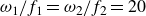 $\omega _1/f_1 = \omega _2/f_2 = 20$
, where
$\omega _1/f_1 = \omega _2/f_2 = 20$
, where
 $\omega _1\neq \omega _2$
and
$\omega _1\neq \omega _2$
and
 $f_1\neq f_2$
. Red and blue markers in the plot correspond to these two combinations of
$f_1\neq f_2$
. Red and blue markers in the plot correspond to these two combinations of
 $\alpha /F$
. The snapshots indicate the vorticity contours at the critical Reynolds numbers for the onset of shedding for each case. The vorticity range is –3 to 3
$\alpha /F$
. The snapshots indicate the vorticity contours at the critical Reynolds numbers for the onset of shedding for each case. The vorticity range is –3 to 3
 ${\rm s}^{-1}$
. See the Supplementary movies of the wake for cases of
${\rm s}^{-1}$
. See the Supplementary movies of the wake for cases of
 $\alpha =2$
,
$\alpha =2$
,
 ${Re}=2$
and
${Re}=2$
and
 $\alpha =4$
,
$\alpha =4$
,
 ${Re}=1$
.
${Re}=1$
.
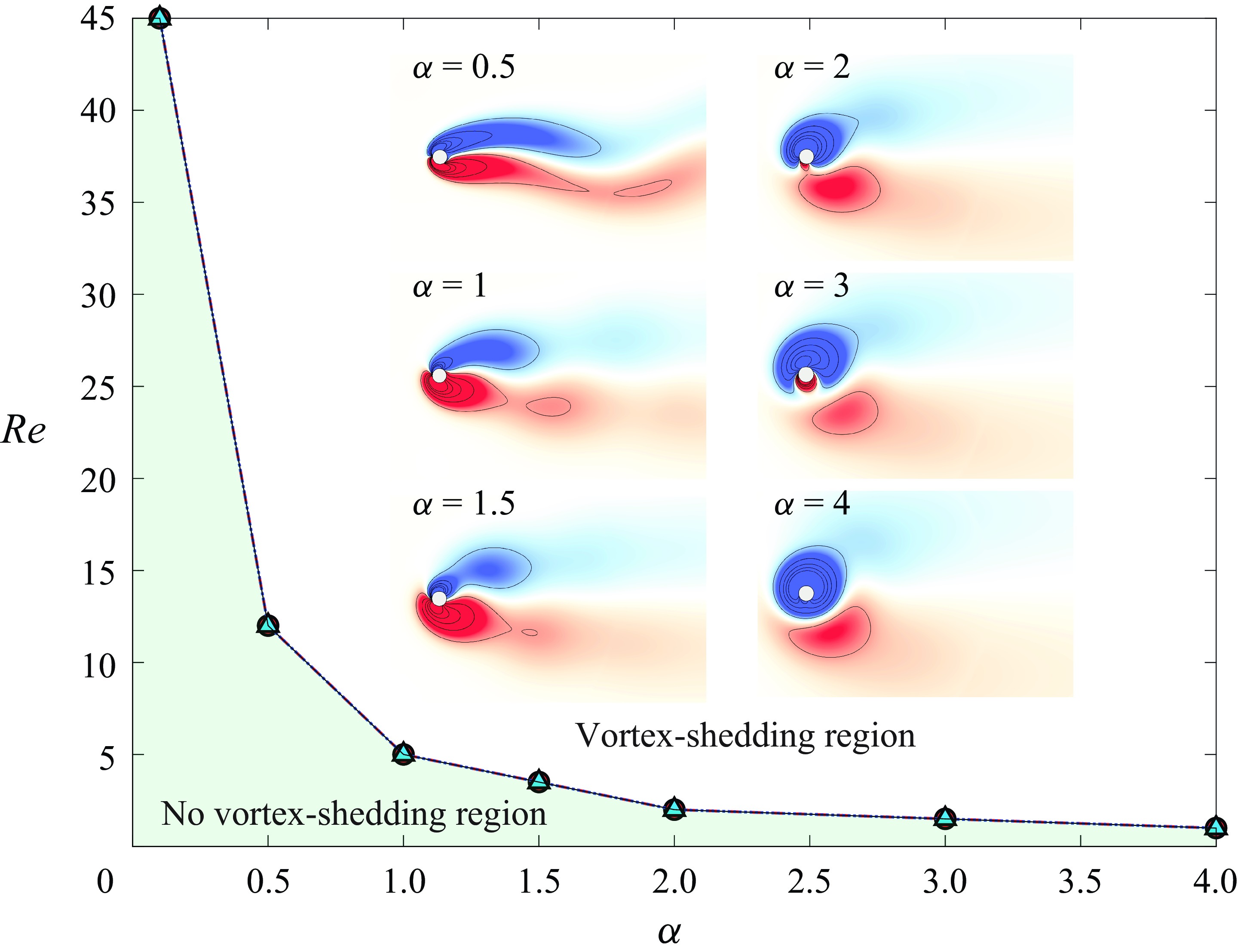
In previous sections, we observed that the vortices can be induced in the wake of a cylinder at subcritical Reynolds numbers when the cylinder is forced to rotate periodically. The question then arises as to what is the minimum Reynolds number at which these vortices can be induced. In figure 10, we show that this minimum Reynolds number for the onset of induced vortices in the wake of the cylinder depends on the rotation rate. As the rotation rate is increased, vortices can be induced in the wake at lower Reynolds numbers. At lower
 $\alpha$
values, the critical Reynolds number to impose shedding in the wake increases to values larger than 45. As
$\alpha$
values, the critical Reynolds number to impose shedding in the wake increases to values larger than 45. As
 $\alpha$
is increased, this critical value decreases quickly to values smaller than 10. We have observed vortex shedding at
$\alpha$
is increased, this critical value decreases quickly to values smaller than 10. We have observed vortex shedding at
 ${Re}=1$
for
${Re}=1$
for
 $\alpha =4$
. Due to the imposed rotation, the local Reynolds number near the cylinder is larger than the Reynolds number based on the incoming flow velocity. The maximum Reynolds number can be described by
$\alpha =4$
. Due to the imposed rotation, the local Reynolds number near the cylinder is larger than the Reynolds number based on the incoming flow velocity. The maximum Reynolds number can be described by
 ${Re}_{max} = {Re} (1+\alpha )$
. By increasing the rotation rate, the amount of vorticity that is generated is increased and a bound vortex is formed. At lower Reynolds numbers, this bound vortex would have stayed attached if the direction of rotation had not been switched since the
${Re}_{max} = {Re} (1+\alpha )$
. By increasing the rotation rate, the amount of vorticity that is generated is increased and a bound vortex is formed. At lower Reynolds numbers, this bound vortex would have stayed attached if the direction of rotation had not been switched since the
 ${Re}_{max}$
does not exceed the critical Reynolds number for vortex shedding (
${Re}_{max}$
does not exceed the critical Reynolds number for vortex shedding (
 ${Re}_{cr} = 47$
). When we change the direction of rotation, the bound vortex is forced to separate and shed in the wake. In the insets of figure 10, we show the vorticity plots for a range of rotation rates at their respective critical Reynolds numbers for the onset of vortex shedding. The plot shown in figure 10 corresponds to
${Re}_{cr} = 47$
). When we change the direction of rotation, the bound vortex is forced to separate and shed in the wake. In the insets of figure 10, we show the vorticity plots for a range of rotation rates at their respective critical Reynolds numbers for the onset of vortex shedding. The plot shown in figure 10 corresponds to
 $\alpha /F=20$
. We have considered two different combinations of
$\alpha /F=20$
. We have considered two different combinations of
 $\omega$
and
$\omega$
and
 $f$
to get
$f$
to get
 $\alpha /F=20$
:
$\alpha /F=20$
:
 $\omega =40 \;{\rm rad\,s}^{-1}$
and
$\omega =40 \;{\rm rad\,s}^{-1}$
and
 $f=2 \; {\rm Hz}$
(red markers) and
$f=2 \; {\rm Hz}$
(red markers) and
 $\omega =80 \; {\rm rad\,s}^{-1}$
and
$\omega =80 \; {\rm rad\,s}^{-1}$
and
 $f=4 \; {\rm Hz}$
(blue markers). Both of these combinations yield the same critical Reynolds number to observe vortex shedding in the wake at a constant rotation rate as the red and blue lines are identical, as shown in figure 10. Therefore, it is the ratio of angular velocity,
$f=4 \; {\rm Hz}$
(blue markers). Both of these combinations yield the same critical Reynolds number to observe vortex shedding in the wake at a constant rotation rate as the red and blue lines are identical, as shown in figure 10. Therefore, it is the ratio of angular velocity,
 $\omega$
, and rotation frequency,
$\omega$
, and rotation frequency,
 $f$
, (
$f$
, (
 $\omega /f \equiv \alpha /F$
) that is important to be considered to pinpoint the minimum Reynolds number for the onset of shedding, and not
$\omega /f \equiv \alpha /F$
) that is important to be considered to pinpoint the minimum Reynolds number for the onset of shedding, and not
 $\omega$
or
$\omega$
or
 $f$
.
$f$
.
5. Conclusions
We study the flow past a periodically rotating cylinder at the subcritical Reynolds numbers, i.e.
 ${Re} \lt 47$
. In the near wake, we show that the Föppl vortices are completely suppressed when periodic rotation is imposed with a large enough rotation rate (
${Re} \lt 47$
. In the near wake, we show that the Föppl vortices are completely suppressed when periodic rotation is imposed with a large enough rotation rate (
 $\alpha \gt 1$
). We have observed three different mechanisms for suppression of Föppl vortices: (a) when a Föppl vortex is generated far from the cylinder and is moved upstream due to the cylinder rotation before it disappears; (b) when two vortices of different sizes are formed in the near wake, one of which moves upstream and the other one downstream, before they both disappear; and (c) when one vortex is formed close to the cylinder and is forced downstream as it disappears.
$\alpha \gt 1$
). We have observed three different mechanisms for suppression of Föppl vortices: (a) when a Föppl vortex is generated far from the cylinder and is moved upstream due to the cylinder rotation before it disappears; (b) when two vortices of different sizes are formed in the near wake, one of which moves upstream and the other one downstream, before they both disappear; and (c) when one vortex is formed close to the cylinder and is forced downstream as it disappears.
In the far wake, we show that forcing the cylinder to rotate periodically induces vortex shedding in the wake and the vortices are shed at a frequency equal to the forcing frequency. We have shown that the ratio of angular velocity,
 $\omega$
, and the frequency of switching the direction of rotation,
$\omega$
, and the frequency of switching the direction of rotation,
 $f$
, (
$f$
, (
 $\omega /f \equiv \alpha /F$
) is an important dimensionless parameter governing this system. The r.m.s.
$\omega /f \equiv \alpha /F$
) is an important dimensionless parameter governing this system. The r.m.s.
 $C_L$
and average
$C_L$
and average
 $C_D$
increases with
$C_D$
increases with
 $\alpha /F$
at a constant rotation rate. With increasing
$\alpha /F$
at a constant rotation rate. With increasing
 $\alpha /F$
, the vortex shedding is delayed to progressively higher rotation rates. Subsequently, the peak of r.m.s.
$\alpha /F$
, the vortex shedding is delayed to progressively higher rotation rates. Subsequently, the peak of r.m.s.
 $C_L$
and average
$C_L$
and average
 $C_D$
occurs at larger rotation rates with increasing
$C_D$
occurs at larger rotation rates with increasing
 $\alpha /F$
. However, if we combine
$\alpha /F$
. However, if we combine
 $\alpha /F$
and rotation rate,
$\alpha /F$
and rotation rate,
 $\alpha$
, to define a new parameter
$\alpha$
, to define a new parameter
 $1/F$
, then the peaks of r.m.s.
$1/F$
, then the peaks of r.m.s.
 $C_L$
and average
$C_L$
and average
 $C_D$
occur at the same values of
$C_D$
occur at the same values of
 $1/F$
for any combinations of
$1/F$
for any combinations of
 $\alpha /F$
and rotation rate (
$\alpha /F$
and rotation rate (
 $\alpha$
). This is observed because the wake pattern remains the same for a constant value of
$\alpha$
). This is observed because the wake pattern remains the same for a constant value of
 $1/F$
, regardless of any combinations of
$1/F$
, regardless of any combinations of
 $\alpha /F$
and
$\alpha /F$
and
 $\alpha$
. We have identified three zones based on the observed wake patterns: (a) weak and localised vortex-shedding zone; (b) vortex-shedding zone; and (c) no shedding zone. For any values of
$\alpha$
. We have identified three zones based on the observed wake patterns: (a) weak and localised vortex-shedding zone; (b) vortex-shedding zone; and (c) no shedding zone. For any values of
 $\alpha /F$
and
$\alpha /F$
and
 $\alpha$
, the wake pattern lies within one of these zones depending on the value of
$\alpha$
, the wake pattern lies within one of these zones depending on the value of
 $1/F$
: weak and localised shedding occurs for lower values of
$1/F$
: weak and localised shedding occurs for lower values of
 $1/F$
, no vortex shedding for higher values of
$1/F$
, no vortex shedding for higher values of
 $1/F$
and sustained vortex shedding for the range in between. If either the rotation rate,
$1/F$
and sustained vortex shedding for the range in between. If either the rotation rate,
 $\alpha$
, or frequency,
$\alpha$
, or frequency,
 $f$
, is known, the value of the other parameter can be inferred to achieve a desired flow pattern based on this categorisation. Therefore,
$f$
, is known, the value of the other parameter can be inferred to achieve a desired flow pattern based on this categorisation. Therefore,
 $1/F$
is the key parameter for characterising the system’s behaviour. We demonstrate that the critical Reynolds number for the onset of vortex shedding decreases by increasing the rotation rate at a constant
$1/F$
is the key parameter for characterising the system’s behaviour. We demonstrate that the critical Reynolds number for the onset of vortex shedding decreases by increasing the rotation rate at a constant
 $\alpha /F$
. We have observed vortices in the wake of the cylinder at Reynolds numbers as low as
$\alpha /F$
. We have observed vortices in the wake of the cylinder at Reynolds numbers as low as
 ${Re}=1$
for
${Re}=1$
for
 $\alpha =4$
at
$\alpha =4$
at
 $\alpha /F=20$
.
$\alpha /F=20$
.
Supplementary movies
Supplementary movies are available at https://doi.org/10.1017/jfm.2025.10442.
Declaration of Interests
The authors report no conflict of interest.


 Open access