


1. Introduction
The stellarator has many unique features that makes it attractive as a fusion energy system. Stellarators are intrinsically steady state, can operate at high plasma density to achieve high gain while potentially relaxing plasma exhaust constraints, have relatively benign responses to magnetohydrodynamic (MHD) instabilities, avoid current-driven disruptions and have low recirculating power requirements. These benefits all provide an opportunity to develop a net electric pilot plant at reduced risk and low capital cost (Gates et al. Reference Gates2018; Baalrud et al. Reference Baalrud, Ferraro, Garrison, Howard, Kuranz, Sarff and Solomon2020). The key tradeoff for these benefits is a highly non-uniform three-dimensional plasma shape and coil configuration, which adds challenges with regards to modeling, design integration, fabrication and maintenance of integrated stellarator systems (Gates et al. Reference Gates2018). In the near term, this requires the development of new tools and approaches to be able to adequately assess and modify blanket designs for stellarators (Häußler et al. Reference Häußler, Warmer and Fischer2018; Palermo et al. Reference Palermo, Warmer and Häußler2021; Lyytinen et al. Reference Lyytinen, Snicker, Virtanen, Palermo, Alguacil, Bogaarts and Warmer2024; Palermo et al. Reference Palermo2024). Regardless of confinement concept, all deuterium-tritium (DT) fusion-based fusion pilot plants (FPPs) require meaningful technological development beyond the burning plasma itself. Critical enabling technologies such as plasma facing components, structural and functional materials and breeding blanket and tritium handling systems need to be further advanced in order to realize reduced-risk commercial systems (US Department of Energy 2021). The breeding blanket and tritium fuel cycle (TFC) related aspects of DT fusion systems in particular embody some of the most fundamental and challenging feasibility and attractiveness issues in the development of commercial fusion energy. Three primary, system driving functions must be satisfied by these components and have strong implications on overall design performance.
The first and most important function relates to the breeding of tritium, which is not naturally occurring in significant quantities and is impossible to stockpile long term due to its short half-life of 12.32 years. The current world-wide tritium inventory is projected to be 30 kg to 40 kg over the next decade, and tritium production in existing CANada Deuterium Uranium (CANDU) fission reactors is less than 0.13 kg per year per reactor (Ni et al. Reference Ni, Wang, Yuan, Jiang and Wu2013; Kovari et al. Reference Kovari, Coleman, Cristescu and Smith2018). In contrast, tritium consumption in high availability fusion power systems will be larger than current production, of the order of 5.6 kg per 100 $\mathrm{MW}_{\mathrm{th}}$
fusion plasma power per full-power year. This drives the requirement that tritium must be bred, extracted and carefully controlled during operation to ensure fuel self-sufficiency and ultimately closure of the DT fuel cycle. Further complicating the matter is the relatively low utilization of tritium in a magnetic fusion energy (MFE) plasma core (order of a fraction to a few percent) which leads to the requirement for effectively and efficiently processing significant amounts of tritium in a continuous fashion (Whyte et al. Reference Whyte, Delaporte-Mathurin, Ferry and Meschini2023). The amount and throughput of tritium that will need to be managed in a fusion power plant will likely be several orders of magnitude larger than the quantities of tritium that have been handled in existing or planned fusion experiments to date, and although relevant technologies exist, they will need to be scaled up in order to handle the expected throughput of commercial systems. These operational inventories drive key engineering considerations such as the tritium start-up inventory, tritium breeding ratio (TBR), safety and waste, and must be minimized to the extent possible.
$\mathrm{MW}_{\mathrm{th}}$
fusion plasma power per full-power year. This drives the requirement that tritium must be bred, extracted and carefully controlled during operation to ensure fuel self-sufficiency and ultimately closure of the DT fuel cycle. Further complicating the matter is the relatively low utilization of tritium in a magnetic fusion energy (MFE) plasma core (order of a fraction to a few percent) which leads to the requirement for effectively and efficiently processing significant amounts of tritium in a continuous fashion (Whyte et al. Reference Whyte, Delaporte-Mathurin, Ferry and Meschini2023). The amount and throughput of tritium that will need to be managed in a fusion power plant will likely be several orders of magnitude larger than the quantities of tritium that have been handled in existing or planned fusion experiments to date, and although relevant technologies exist, they will need to be scaled up in order to handle the expected throughput of commercial systems. These operational inventories drive key engineering considerations such as the tritium start-up inventory, tritium breeding ratio (TBR), safety and waste, and must be minimized to the extent possible.
In addition to fuel self-sufficiency, the breeder blanket will also play a pivotal role in the overall thermal efficiency of DT fusion energy systems. It must extract heat originating both from volumetric heat generation caused by neutrons, subsequent prompt photon energy deposition and nuclear reactions inside the blanket as well as plasma radiation towards the first wall, which is typically integrated on the surface of the blanket for neutron economy reasons (Hesch et al. Reference Hesch, Boccaccini and Stieglitz2018). Since the blanket is anticipated to account for 80 %–90 % of the plasma facing surface, the majority of the energy of the DT fusion reaction is imparted into high energy neutrons (approximately 80 %), and MFE systems typically run with a strong radiative fraction (90 %–95 %), it is conservatively estimated that at least 75 % of the overall system heat loads will reside in the blanket. This heat must be effectively removed both for effective thermal conversion but also to keep materials and components within operating temperature limits. This is done through the forced flow of one or more coolants, depending on design. The characteristics of this coolant flow, including pumping power requirements, and its coupling to a thermal conversion system will dictate both power production and overall power conversion efficiency of an energy producing system.
Finally, the breeder blanket will be responsible for providing a significant amount of nuclear shielding for device lifetime components. For MFE devices this typically includes the plasma confining magnetic field coils, which are relatively sensitive to radiation, but can also include other large components such as the vacuum vessel, which may be too costly or difficult to easily replace over the life of the device. A key consideration of any fusion blanket design is its efficacy in both slowing and absorbing neutrons (El-Guebaly Reference El-Guebaly2018; Pereslavtsev et al. Reference Pereslavtsev, Hernández, Zhou, Lu, Wegmann and Fischer2019), given the relatively large penetration length scales of the energetic DT fusion neutrons (order of meters) as well as the requirement to reduce the neutron flux by approximately four orders of magnitude from the first wall to the coil structures. In addition to the minimum blanket volume required for breeding, the optimized shielding performance of the blanket, including any integrated dedicated shield material, will play a factor in determining the minimum allowable plasma-to-magnet spacing and ultimately drive the size of MFE devices such as stellarators. This shielding will also play a vital role in safety and activated material management considerations of a DT energy system.
In addition to serving these core functions, in-vessel components such as the blanket will be subjected to, and must survive, immensely harsh conditions, including a combination of extreme radiation, high heat, mechanical stress and volatile chemical environments. This represents one of the ultimate challenges in materials science and engineering, and it is expected that the performance of these components will ultimately dictate the economic, safety and environmental attractiveness of any given fusion system (Aubert et al. Reference Aubert2018). At present, the behavior and reliability of materials subjected to this environment have relatively high uncertainty, and this uncertainty affects design choices as well as research and development (R&D) needs.
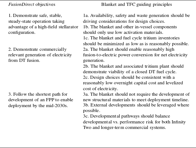
For these reasons, the selection, design and optimization of a suitable blanket configuration for an advanced high-field stellarator concept is seen as a key feasibility issue and has been incorporated as a vital and necessary part of the Infinity Two physics basis from the onset. The purpose of this paper is to document at a high level the selection process, including identification of objectives, analyses and findings. As outlined in the overview (Hegna et al. Reference Hegna2025), Type One Energy Group Inc. (T1E) is pursuing an ambitious and uniquely direct path to fusion known as the FusionDirect program, the cornerstone of which is the disciplined adherence to a technology development path with the lowest possible risk and shortest possible schedule to realize a high-field stellarator FPP. The overarching objective of the FusionDirect program’s mission is to demonstrate safe, stable, steady-state operation of a high-field stellarator capable of reliably generating clean, sustainable electricity for commercial applications by the mid-2030s. Cascading from this objective, several high-level guidelines were imposed on the T1E blanket and TFC program at an early stage to ensure the technology choices and subsequent technology development program remain compatible with the overarching missions embodied by FusionDirect. These guidelines are summarized in table 1.
FusionDirect objectives and subsequent blanket and TFC guiding principles.
2. Technical background
Over the past decades countless studies have examined various breeder blanket concepts for both MFE and inertial fusion energy applications. Until a few years ago, the primary drivers of this research were public research organizations involved in government sponsored research world-wide. One of the main focal points of this research is on the development of breeder blanket mock-ups to be tested on the ITER tokamak currently under construction in Cadarache, France, known as the test blanket modules (Giancarli et al. Reference Giancarli2020). The basic concept of all breeder blankets envisaged for DT fusion focuses on achieving tritium self-sufficiency via conversion of lithium to tritium by means of nuclear reactions. Lithium may be present as a liquid metal, liquid eutectic alloy, molten salt or in solid form such as a lithium-bearing ceramic. At the most fundamental level, a blanket consists of this breeding medium in an assembly fabricated of fusion relevant structural materials, a flowing coolant used to extract heat and a neutron multiplier for increased neutron economy as needed. Families of existing low activation structural materials under consideration include reduced activation ferritic martensitic (RAFM) steels, advanced steels (castable nanostructured alloys (CNAs) and oxide dispersion strengthened (ODS) steels), vanadium alloys or silicon carbide (SiC) based ceramic matrix composites. Coolants under consideration include water, helium (He), carbon dioxide (CO $_{2}$
) or self-cooling through the flow of liquid breeding media. Neutron multipliers include beryllium and lead-based materials. A non-exhaustive, general summary of popular combinations considered in the literature can be seen in table 2.
$_{2}$
) or self-cooling through the flow of liquid breeding media. Neutron multipliers include beryllium and lead-based materials. A non-exhaustive, general summary of popular combinations considered in the literature can be seen in table 2.
Primary blanket combinations under consideration in literature.
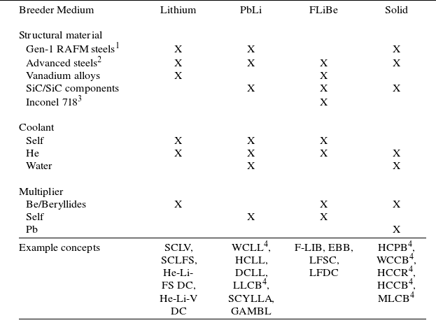
1 F82H, EUROFER97.
2 CNA, ODS.
3 Inconel is not considered to be a low activation material.
4 Blanket concepts currently proposed for the ITER Test Blanket Modules program.
In order to help narrow down the field of extremely diverse concepts, six reference concepts were identified from design studies in the literature. These reference concepts are meant to be indicative of the broad ‘family’ of designs defined by the selection of primary components, namely, breeding medium, structure, coolant and neutron multiplier, as well as the relevant regimes in which they are employed. A brief description of each reference concept is included below, and readers are directed to the referenced publications for further details. The first three reference concepts represent some of the most commonly explored designs to date, mainly owing to their inclusion in both the ITER test blanket modules and international fusion energy programs. The focus of these designs tends to be on near-term technical feasibility.
The helium-cooled pebble bed (HCPB) concept is one of two blanket concepts selected for the EU Demonstration Power Plant (EU DEMO) (Hernández et al. 2023). The current reference HCPB design is the so-called ‘pin’ design, which is based on a radial arrangement of ceramic fuel-breeder pins using RAFM structure (EUROFER97) for optimized neutronics performance. Each pin consists of two concentric tubes that form the inner and outer cladding which are filled with the tritium breeding material (Karlsruhe lithium orthosilicate advanced ceramic breeder pebbles). The volume between pins is filled by hexagonal prismatic blocks of neutron multiplier material (Be $_{12}$
Ti). Each pin is cooled with high pressure He. A separate stream of He purge gas doped with hydrogen is flowed through the breeder pins and multiplier prismatic blocks for tritium removal (Hernández et al. Reference Hernández2019, Reference Hernández2020; Zhou et al. Reference Zhou, Hernández, Pereslavtsev, Kiss, Retheesh, Maqueda and Park2023a
).
$_{12}$
Ti). Each pin is cooled with high pressure He. A separate stream of He purge gas doped with hydrogen is flowed through the breeder pins and multiplier prismatic blocks for tritium removal (Hernández et al. Reference Hernández2019, Reference Hernández2020; Zhou et al. Reference Zhou, Hernández, Pereslavtsev, Kiss, Retheesh, Maqueda and Park2023a
).
The helium-cooled lithium lead (HCLL) concept was one of the four candidate blankets selected for the EU DEMO prior to down-selection at the preconceptual design phase (Aubert et al. Reference Aubert2018). The general concept of the HCLL breeding blanket consists of several boxes stiffened by actively He-cooled plates, between which the PbLi neutron multiplier, tritium breeder and carrier medium slowly flow. The structural material of choice is RAFM steel (EUROFER97). The current reference design is known as the ‘advanced-plus’ HCLL, which is aimed at providing optimized breeding, shielding and thermo-mechanical performance through the implementation of only thin horizontal stiffening plates (Aubert et al. Reference Aubert2018; Boullon et al. Reference Boullon, Aubert, Aiello, Jaboulay and Morin2019; Jaboulay et al. Reference Jaboulay, Aiello, Aubert and Boullon2019).
The dual coolant lithium lead (DCLL) concept has been considered by a number of public programs including both the EU (Rapisarda et al. Reference Rapisarda, Fernández-Berceruelo, García, García, Garcinuño, González, Moreno, Palermo, Urgorri and Ibarra2021) and US (Kessel et al. Reference Kessel2018) due both to its readiness for deployment as well as to its high degree of design flexibility and potential for extrapolated performance. This blanket concept uses RAFM steels (F82H or EUROFER97) or higher temperature and/or radiation resistant variants (such as the CNA or ODS steels) as structural material. The primary coolant is He and the PbLi liquid metal acts as a breeder, multiplier, tritium carrier medium and secondary coolant. SiC-composite flow channel inserts are typically employed as electrical and thermal insulators between the PbLi and the RAFM steel in the blanket to minimize MHD pressure drops for the liquid metal. The details of the individual DCLL designs can vary widely depending on materials selection, PbLi flow speed and operating temperature (Smolentsev et al. Reference Smolentsev, Morley, Abdou and Malang2015). The reference DCLL design used in this analysis was the same as that employed on the US Fusion Nuclear Science Facility (FNSF) study (Kessel et al. Reference Kessel2018), which was chosen due to the availability of design details, although higher performing concepts are also under development (Rapisarda et al. Reference Rapisarda, Fernández-Berceruelo, García, García, Garcinuño, González, Moreno, Palermo, Urgorri and Ibarra2021).
In addition to these more traditional designs, a number of higher-risk, higher-reward concepts have also appeared in the literature. These predominantly focus on self-cooled blankets, which were first conceived in the 1980s as an optimal solution which allows for design simplification and increased performance compared with the separately cooled concepts highlighted in the previous section. The initial design space for these concepts was mostly explored through the US blanket (Smith et al. Reference Smith, Baker, Sze, Morgan, Abdou, Piet, Schultz, Moir and Gordon1985; Raffray et al. Reference Raffray, Akiba, Chuyanov, Giancarli and Malang2002) and Advanced Research Innovation and Evaluation Study (ARIES) programs (University of Wisconsin-Madison 2024a) due to their potential attractiveness for commercial systems. Currently, no self-cooled blanket has been developed beyond the concept exploration phase primarily due to the limited need to develop advanced blanket technology for fusion experiments such as ITER (Giancarli et al. Reference Giancarli2020), but also due to the perceived maturity of suitable materials required for implementing such blanket designs (Raffray et al. Reference Raffray, Akiba, Chuyanov, Giancarli and Malang2002). The emergence of the fusion private industry has renewed interest in these concepts, with three MFE-relevant designs identified in this study.
The first is the self-cooled lithium lead (SCLL) concept which is being championed by Kyoto Fusioneering (Pearson et al. Reference Pearson, Baus, Konishi, Mukai, D’Angio and Takeda2022). This design builds on the ARIES-Advanced and Conservative Tokamak (ACT1) blanket concept, which is embodied by the choice of SiC composite structural material and PbLi eutectic, which serves as the breeder, coolant, multiplier and tritium carrier (Kessel et al. Reference Kessel2015). An optional additional Be neutron multiplier known as a ‘booster’ or reflector are also variations on the design, which can be included or adjusted based on performance requirements.
The second is the self-cooled lithium vanadium (SCLV) concept which builds on the ARIES-reversed-shear tokamak blanket concept (Tillack et al. Reference Tillack, Malang, Waganer, Wang, Sze, El-Guebaly, Wong, Crowell, Mau and Bromberg1997; Sze et al. Reference Sze1998) and historic R&D activities at the Argonne National Laboratory Blanket program (Mattas et al. Reference Mattas, Smith, Reed, Park, Kirillov, Strebkov, Rusanov and Votinov1998; Gohar et al. Reference Gohar, Majumdar and Smith2000). The SCLV is embodied by the choice of a vanadium alloy (typically V-4Cr4Ti although advanced V alloys are also under development (Aaron Li Reference Li2024)) as structural material and pure lithium metal which serves as the breeder, coolant, multiplier and tritium carrier. An external multiplier and/or reflector may or may not be required depending on the design. Historically, lithium vanadium concepts have not been strongly considered for separate or dual-cooled designs because of concerns with oxidation and embrittlement by the uptake of interstitial atoms including oxygen, carbon, nitrogen or hydrogen (Muroga et al. Reference Muroga, Chen, Chernov, Kurtz and Le Flem2014). However, both helium-cooled lithium vanadium (Lord et al. Reference Lord, Bennett, Harrington, Cooper, Lee-Lane, Cureton, Olde, Thompson, Jayasundara and Meatyard2024) and dual coolant lithium vanadium (Li Reference Li2024) have been proposed recently, although these designs were not incorporated into this analysis due to time constraints and lack of sufficient technical detail.
The third is a self-cooled molten salt concept which is being developed by the Massachusetts Institute of Technology in collaboration with Commonwealth Fusion Systems (Sorbom et al. Reference Sorbom2015; Ferry et al. Reference Ferry, Woller, Peterson, Sorensen and Whyte2023). This design builds on US blanket (Sze et al. Reference Sze, Jung, Cheng, Piet and Klein1986; Wong et al. Reference Wong2005) and ITER program designs (Abdou et al. Reference Abdou, Sze, Wong, Sawan, Ying, Morley and Malang2005), but with the major modification of removing flow channels and replacing them with a continuous pool of quasi-stagnant salt. This allows for the removal of a significant fraction of structural material for enhanced breeding performance, which historically was a challenge for molten salt concepts. The salt typically chosen for this application is FLiBe (2:1 molar mixture of LiF-BeF $_{2}$
salt eutectic) due to its lithium content and historical usage in the molten salt reactor experiment experiment at ORNL, which provides for a relatively robust operational baseline (Wong et al. Reference Wong2005). This concept, known as the FLiBe liquid immersion blanket (F-LIB), initially proposes to utilize Inconel-718 as the structural material and Be as a neutron multiplier. It is important to note that Inconel-718 is not considered a low activation material due to its high nickel content, and so is not viable in the long term. However, it may be an acceptable choice for a low volume, one-of-a-kind plant assuming that suitable materials are identified and matured prior to full commercialization, which is an area of ongoing development (Commonwealth Fusion Systems 2024).
$_{2}$
salt eutectic) due to its lithium content and historical usage in the molten salt reactor experiment experiment at ORNL, which provides for a relatively robust operational baseline (Wong et al. Reference Wong2005). This concept, known as the FLiBe liquid immersion blanket (F-LIB), initially proposes to utilize Inconel-718 as the structural material and Be as a neutron multiplier. It is important to note that Inconel-718 is not considered a low activation material due to its high nickel content, and so is not viable in the long term. However, it may be an acceptable choice for a low volume, one-of-a-kind plant assuming that suitable materials are identified and matured prior to full commercialization, which is an area of ongoing development (Commonwealth Fusion Systems 2024).
It should also be noted that several water-cooled designs were identified, but ultimately not explored. Although water cooling enjoys a relatively robust technology basis, including application as a coolant in fossil and nuclear fission power plants, it was recognized that water-cooled systems have some significant challenges which limit their potential attractiveness for commercial DT fusion devices and ultimately were not an attractive pathway for the FusionDirect program. For a detailed discussion of these challenges, as well a perspective on why the US fusion program has not historically favored water as a coolant, readers are referred to Tillack et al. (Reference Tillack, Humrickhouse, Malang and Rowcliffe2015).
The following sections of this paper detail the process by which each of the six blanket concepts were analyzed parametrically to better understand differences in performance. Section 3 details the neutronics analysis via Monte Carlo techniques, § 4 details the thermal analysis evaluating system-level integration and performance with a Rankine cycle and § 5 details a TFC analysis using the residence time method (RTM). In each of these sections, the associated tools were also used to evaluate the Infinity Two FPP baseline plasma physics configuration. Section 6 combines the outcomes of these quantitative analyses with a qualitative analysis of technical maturity and other performance risks and discusses implications of various blanket choices on the overall FusionDirect program. Section 7 details the conclusions of this study.
3. Neutronics analysis
3.1. Introduction
One of the most significant challenges in designing a stellarator-based fusion energy system is the selection of a blanket concept optimized for its complex geometry. From a large phase space of blanket concepts, a design and associated radial build must be chosen which is able to satisfy both tritium self-sufficiency and shielding requirements, constrained to as reasonably small build depth as possible in order to satisfy space limitations between the plasma and the magnets. For tritium self-sufficiency, the TBR must be greater than unity depending on the specifics of the TFC and objectives for doubling time. In the neutronics portion of this study, a TBR of 1.35 was set as the viability target, understanding that detailed system-level requirements have not yet been set, but also that significant margins may be necessary to accommodate additional fidelity in design details (El-Guebaly Reference El-Guebaly2018). This includes detailed component geometries as well as the inclusion of the divertor, penetrations and gaps which will remove volume from the breeder layer. For shielding, conservative lifetime limits included: (i) restrictions on the fast neutron fluence at the magnets to below 5 ${\times}$
10
${\times}$
10 $^{18}$
n cm
$^{18}$
n cm $^{-2}$
for super conductor degradation concerns (El-Guebaly Reference El-Guebaly2018), (ii) He production/damage in the vacuum vessel below 1 atomic parts per million (appm) to ensure reweldability (El-Guebaly Reference El-Guebaly2018) and (iii) 5 displacements per atom (dpa) as a conservative limit of radiation induced embrittlement of austenitic stainless steels (such as 304 and 316) used for the vacuum vessel (Zinkle & Was Reference Zinkle and Was2013). The target lifetime used in this study was five full-power years based on preliminary requirements and objectives of Infinity Two.
$^{-2}$
for super conductor degradation concerns (El-Guebaly Reference El-Guebaly2018), (ii) He production/damage in the vacuum vessel below 1 atomic parts per million (appm) to ensure reweldability (El-Guebaly Reference El-Guebaly2018) and (iii) 5 displacements per atom (dpa) as a conservative limit of radiation induced embrittlement of austenitic stainless steels (such as 304 and 316) used for the vacuum vessel (Zinkle & Was Reference Zinkle and Was2013). The target lifetime used in this study was five full-power years based on preliminary requirements and objectives of Infinity Two.
The body of this section details the approach for determining optimal radial builds for each family of breeder concepts using computational neutronic simulations, comparing the blanket concepts based on their optimal radial builds and arriving at the recommendation of the leading concept from a neutronics perspective. The radial build used for this analysis was based on the FNSF study (Kessel et al. Reference Kessel2018), excluding the blanket and magnets portions, which were drawn from the literature and T1E internal design activities, respectively. A key differentiator of this study with respect to other design activities was the decision to not allow water within the vacuum boundary for engineering and safety considerations. This resulted in the creation of a water-cooled low-temperature shield as a layer external to the helium-cooled vacuum vessel which contains both the blanket and the high-temperature shield.
All neutronics simulations were performed using OpenMC (Romano et al. Reference Romano, Horelik, Herman, Nelson, Forget and Smith2015) with FENDL 3.2c neutron cross-section data library, ENDF/B-VIII.0 supplement for Nd neutron and all element photon reaction cross-sections. The focus of the subsequent analysis sections is to outline the implication of blanket choices on radiation transport and subsequent effects, including neutron flux/shielding attenuation, tritium breeding, nuclear heating, material damage to blanket structures and He production by nuclear transmutation.
3.2. Parametric analysis of breeder blanket concepts
A simplified one-dimensional neutronics analysis was used to perform a comparative evaluation of six blanket concepts based on their breeding efficiency with breeder thickness, as well as the shielding efficiency with thickness of breeder and shield layers. These one-dimensional simulations were performed using a plasma ring source (Shimwell, Reference Shimwell2021) and material-homogenized toroidal shell representations of the layers of interest (first wall, breeder, vacuum vessel, shielding, magnet coil winding pack, etc.). Although not fully representative of complex three-dimensional stellarator geometries, this type of simplified quantitative comparison is helpful to inform the down-selection of blanket concepts at early design stages (El-Guebaly et al. Reference El-Guebaly, Raffray, Malang, Lyon and Ku2005, Reference El-Guebaly2008). Models comprising concentric toroidal shells of homogenized blanket layers were generated based on the following references:
-
a. HCPB (Zhou et al. Reference Zhou, Hernández, Pereslavtsev, Kiss, Retheesh, Maqueda and Park2023a ), shown in figure 10 in Appendix A.
-
b. HCLL (Aubert et al. Reference Aubert2018), shown in figure 11 in Appendix A.
-
c. DCLL (Davis et al. Reference Davis, Harb, El-Guebaly, Wilson and Marriott2018), shown in figure 12 in Appendix A.
-
d. SCLL (Kessel et al. Reference Kessel2015), shown in figure 13 in Appendix A.
-
e. SCLV (Gohar et al. Reference Gohar, Majumdar and Smith2000; Kirillov et al. Reference Kirillov, Danilov, Sidorenkov, Strebkov, Mattas, Gohar, Hua and Smith1998), shown in figure 14 in Appendix A.
-
f. F-LIB (Segantin et al. Reference Segantin, Testoni, Hartwig, Whyte and Zucchetti2020, Reference Segantin, Meschini, Testoni and Zucchetti2022; Bae et al. Reference Bae, Peterson and Shimwell2022), shown in figure 15 in Appendix A.
The layers whose thickness were varied are denoted in the diagrams with turquoise for breeder layer and blue for shields. All other layers without ‘variable thickness’ designation in the diagrams were fixed in the parametric models. Toroidal shell models were parametrically generated for each blanket concept to cover the domain where the breeder thickness varies from 10 to 100 cm and the two shielding thicknesses vary from 10 to 60 cm.
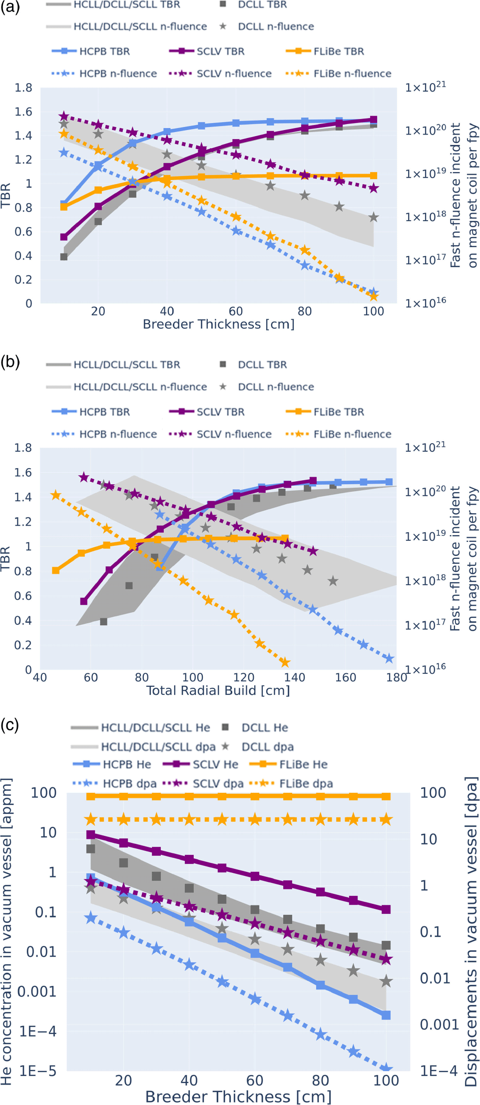
(a) The TBR and fast neutron fluence on the magnets vs homogenized breeder layer thickness. (b) The He concentration produced by transmutation in vacuum vessel per full-power year and dpa in vacuum vessel per full-power year vs breeder thickness. (c) The TBR and fast neutron fluence on the magnets vs radial build thickness reflecting that the blanket concepts differ in associated manifold sizes.
For each breeder blanket concept, in addition to variation in breeder and shielding thickness, parametric studies were also performed to determine the variation in neutronic response for various relevant parameters including $^{6}$
Li enrichment, multiplier material and composition, composition of structural material and composition of coolant material. The reference cases listed in the previous section were used as a basis for comparison. In addition, for the HCPB concept the neutronic performance of several novel breeder materials of interest was also studied. Figure 1(a) shows the change in TBR and full-power year fast neutron fluence incident on the magnets with increasing breeder layer thickness and a shielding thickness of 10 cm for the high-temperature shield and low-temperature shield, which is the minimum shielding in the cases studied. Figure 1(b) shows the same TBR and fast neutron fluence incident on magnets with increasing breeder thickness as in figure 1(a), but with respect to total radial build to reflect the fact that different breeder concepts differ in associated manifold sizes and support structures. Figure 1(c) shows He production and damage in the vacuum vessel with increasing breeder layer thickness. In figure 1(c) the concentration of He in the vacuum vessel material in appm was calculated from the He production tally in the vacuum vessel normalized to the atomic number density of material in the cell volume. The expected dpa in the vacuum vessel material was calculated from the mean damage energy tally in Fe for cases where the vacuum vessel material is steel (for the blanket concepts HCPB, DCLL, HCLL, SCLL); in vanadium, titanium and chromium for cases where the vacuum vessel material is V-4Ti-4Cr (SCLV); in nickel, iron and chromium, for cases where the vacuum vessel material is Inconel 718 (F-LIB). Data reduction was performed according to the following heuristic: the minimum breeder thickness was determined for each blanket concept for 10 cm each of high-temperature and low-temperature shielding which meets the magnet shielding constraints of less than 1
$^{6}$
Li enrichment, multiplier material and composition, composition of structural material and composition of coolant material. The reference cases listed in the previous section were used as a basis for comparison. In addition, for the HCPB concept the neutronic performance of several novel breeder materials of interest was also studied. Figure 1(a) shows the change in TBR and full-power year fast neutron fluence incident on the magnets with increasing breeder layer thickness and a shielding thickness of 10 cm for the high-temperature shield and low-temperature shield, which is the minimum shielding in the cases studied. Figure 1(b) shows the same TBR and fast neutron fluence incident on magnets with increasing breeder thickness as in figure 1(a), but with respect to total radial build to reflect the fact that different breeder concepts differ in associated manifold sizes and support structures. Figure 1(c) shows He production and damage in the vacuum vessel with increasing breeder layer thickness. In figure 1(c) the concentration of He in the vacuum vessel material in appm was calculated from the He production tally in the vacuum vessel normalized to the atomic number density of material in the cell volume. The expected dpa in the vacuum vessel material was calculated from the mean damage energy tally in Fe for cases where the vacuum vessel material is steel (for the blanket concepts HCPB, DCLL, HCLL, SCLL); in vanadium, titanium and chromium for cases where the vacuum vessel material is V-4Ti-4Cr (SCLV); in nickel, iron and chromium, for cases where the vacuum vessel material is Inconel 718 (F-LIB). Data reduction was performed according to the following heuristic: the minimum breeder thickness was determined for each blanket concept for 10 cm each of high-temperature and low-temperature shielding which meets the magnet shielding constraints of less than 1 ${\times}$
10
${\times}$
10 $^{18}$
n cm
$^{18}$
n cm $^{-2}$
per full-power year. The associated TBR was noted as well as whether this radial build satisfies vacuum vessel damage constraints. The results of this data reduction are listed in table 3. In this way the blanket concepts can be compared simultaneously on 3 axes: compactness of radial build, TBR and shielding.
$^{-2}$
per full-power year. The associated TBR was noted as well as whether this radial build satisfies vacuum vessel damage constraints. The results of this data reduction are listed in table 3. In this way the blanket concepts can be compared simultaneously on 3 axes: compactness of radial build, TBR and shielding.
Upper bound of tritium breeding performance for the blanket concepts of interest under standardized geometry and the minimum shielding needed to meet magnet and vacuum vessel lifetime requirements.
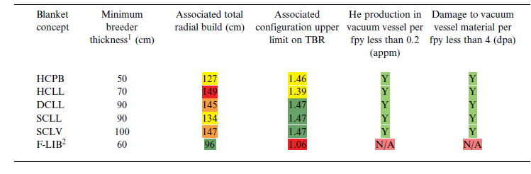
1 Minimum breeder thickness that meets n-fluence limit on magnets approximately 1E18 n/fpy.
2 No shielding between first wall and vacuum vessel incorporated into design; this design concept is incompatible with vacuum vessel as lifetime component.
These results indicate that the HCPB concept promises a very high upper bound TBR of 1.46 for a relatively mid-sized radial build, presenting a compromise between high tritium breeding performance and compact radial build. In addition, it is evident that the HCPB concept saturates at almost the highest TBR with the lowest breeder material loading. Finally, it is clear that solid ceramic breeder materials afford the greatest supplemental shielding effect to both the vacuum vessel and magnets for the most compact radial build, which benefits the economics of the T1E design in both minimizing the size and maximizing the lifetime of the device by minimizing the damage on lifetime components. This performance can be attributed to the higher atomic number density of the solid breeder materials even in the case of a pebble-based design, as well as the utilization of Be-based materials for highly effective neutron multiplication.
The breeding and shielding with material thickness of the DCLL was found to be intermediate between the SCLL and HCLL. This is expected because the DCLL supplements He cooling with PbLi cooling to offset some of the He manifold thickness resulting in a more compact radial build than the HCLL but not quite as compact as the SCLL. On the other hand, the DCLL exhibits a higher TBR than the HCLL as expected due to the higher PbLi mass loading in the device. Of all liquid PbLi concepts, the SCLL is by far the most compact and tritium breeding-efficient. From figure 1 and table 3, it can be seen that the PbLi designs and SCLV promise the highest saturated TBR (approximately 1.47), but also have the highest associated total radial build requirements, with their performance being comparable. The key difference between these concepts is the requirement for $^{6}$
Li enrichment, where the pure lithium holds a clear advantage by utilizing natural enrichment versus the 90 % enrichment utilized by the PbLi concepts. The large radial builds required for the liquid metal concepts can be attributed to the lower moderation and multiplication efficacy of liquid metals, which negatively impacts both breeding and shielding performance.
$^{6}$
Li enrichment, where the pure lithium holds a clear advantage by utilizing natural enrichment versus the 90 % enrichment utilized by the PbLi concepts. The large radial builds required for the liquid metal concepts can be attributed to the lower moderation and multiplication efficacy of liquid metals, which negatively impacts both breeding and shielding performance.
Figure 1 and table 3 show that the F-LIB concept achieves a TBR greater than unity at the smallest radial builds, but it also saturates at lower values (1.09) and ultimately is the only concept which fails to meet the target TBR of 1.35. Regarding shielding, it is evident that the F-LIB concept provides the greatest shielding to the magnets thanks to the high neutron moderating and absorbing properties of FLiBe constituent nuclides, although it is this shielding capability that ultimately limits the saturated TBR due to self-shielding effects. These findings are consistent with prior neutronics studies of the F-LIB (Segantin et al. Reference Segantin, Testoni, Hartwig, Whyte and Zucchetti2020), and although opportunities exist for refinement and potential improvement of the TBR in FLiBe-based blankets through the careful tailoring of $^{6}$
Li enrichment, multiplier content and detailed layout (Segantin et al. Reference Segantin, Testoni, Hartwig, Whyte and Zucchetti2020; Boullon et al. Reference Boullon, Jaboulay and Aubert2021), such optimizations were outside the scope of this study. In addition, the F-LIB concept is not conceived with the intention of the vacuum vessel being a lifetime component, which explains why its design precludes any substantial shielding of the vacuum vessel and neutron fluence is permitted to exceed material damage limits. Finally, it should be noted that this particular reference design assumed zero structure in the blanket, which is not currently envisioned as being applicable to the T1E high-field stellarator approach. This is due to specific design decisions which require structural elements for supporting the vacuum vessel, tank sector separators for modularity and penetrations for plasma access. In addition to the lowest saturated TBR, the F-LIB concept was also found to be sensitive to this additional structure requirement which negatively impacts the TBR.
$^{6}$
Li enrichment, multiplier content and detailed layout (Segantin et al. Reference Segantin, Testoni, Hartwig, Whyte and Zucchetti2020; Boullon et al. Reference Boullon, Jaboulay and Aubert2021), such optimizations were outside the scope of this study. In addition, the F-LIB concept is not conceived with the intention of the vacuum vessel being a lifetime component, which explains why its design precludes any substantial shielding of the vacuum vessel and neutron fluence is permitted to exceed material damage limits. Finally, it should be noted that this particular reference design assumed zero structure in the blanket, which is not currently envisioned as being applicable to the T1E high-field stellarator approach. This is due to specific design decisions which require structural elements for supporting the vacuum vessel, tank sector separators for modularity and penetrations for plasma access. In addition to the lowest saturated TBR, the F-LIB concept was also found to be sensitive to this additional structure requirement which negatively impacts the TBR.
As a supplement to the reference configurations above, a wide variety of neutronics calculations in simplified geometric approximations were performed to better probe and understand the overall design space for breeder concepts consistent with prior studies (Zheng & Wu Reference Zheng and Wu2003), but using modern tools and more representative geometries. One such example is shown in figure 2, where the TBR was calculated for various breeder materials mixed homogeneously with concentrations of multiplier (Be $_{12}$
Ti) increasing in the y-direction. The relationship between breeder thickness and TBR was then calculated at enrichments increasing in the x-direction and with varying multiplier material content in the breeder region. This analysis enables a comparison of breeder materials from the point of view of resource utilization, where designs utilizing low
$_{12}$
Ti) increasing in the y-direction. The relationship between breeder thickness and TBR was then calculated at enrichments increasing in the x-direction and with varying multiplier material content in the breeder region. This analysis enables a comparison of breeder materials from the point of view of resource utilization, where designs utilizing low $^{6}$
Li enrichment and low Be multiplier loading are most desirable, although the detailed optimization of engineering, safety and cost trade-off between these two aspects is still an open question requiring resolution. The compactness of the radial build is reflected by the breeder thickness as a proxy.
$^{6}$
Li enrichment and low Be multiplier loading are most desirable, although the detailed optimization of engineering, safety and cost trade-off between these two aspects is still an open question requiring resolution. The compactness of the radial build is reflected by the breeder thickness as a proxy.
Relationships of breeder thickness and TBR using (a) natural lithium without multiplying material, (b) 60 wt % $^{6}$
Li enrichment without multiplying material, (c) 90 wt %
$^{6}$
Li enrichment without multiplying material, (c) 90 wt % $^{6}$
Li enrichment without multiplying material, (d) natural lithium with 45 wt % multiplying material, (e) 60 wt %
$^{6}$
Li enrichment without multiplying material, (d) natural lithium with 45 wt % multiplying material, (e) 60 wt % $^{6}$
Li enrichment with 45 wt % multiplying material, (f) 90 wt %
$^{6}$
Li enrichment with 45 wt % multiplying material, (f) 90 wt % $^{6}$
Li enrichment with 45 wt % multiplying material, (g) natural lithium with 90 wt % multiplying material, (h) 60 wt %
$^{6}$
Li enrichment with 45 wt % multiplying material, (g) natural lithium with 90 wt % multiplying material, (h) 60 wt % $^{6}$
Li enrichment with 90 wt % multiplying material and (i) 90 wt %
$^{6}$
Li enrichment with 90 wt % multiplying material and (i) 90 wt % $^{6}$
Li enrichment with 90 wt % multiplying material. For the three ceramic breeder materials of interest, the blue shaded regions show the maximum TBR for the lowest resource utilization.
$^{6}$
Li enrichment with 90 wt % multiplying material. For the three ceramic breeder materials of interest, the blue shaded regions show the maximum TBR for the lowest resource utilization.
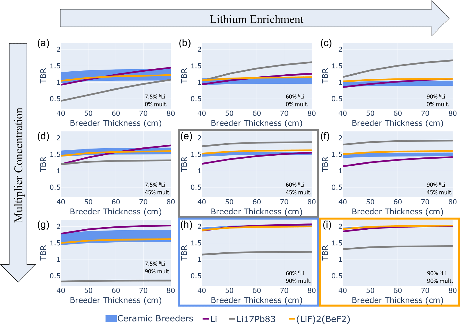
The superiority of solid breeder materials Li $_{2}$
O, Li
$_{2}$
O, Li $_{4}$
SiO
$_{4}$
SiO $_{4}$
and Li
$_{4}$
and Li $_{2}$
TiO
$_{2}$
TiO $_{3}$
is highlighted by figure 2(d) where compact radial builds with breeder thicknesses as low as 50 cm, multiplier concentration as low as 45 weight percent (wt %) and
$_{3}$
is highlighted by figure 2(d) where compact radial builds with breeder thicknesses as low as 50 cm, multiplier concentration as low as 45 weight percent (wt %) and $^{6}$
Li enrichment as low as natural
$^{6}$
Li enrichment as low as natural $^{6}$
Li abundance can achieve TBR approximately 1.6, the highest of all materials. Using natural lithium and less than 45 wt % of multiplying material mixed with the breeder material, Li
$^{6}$
Li abundance can achieve TBR approximately 1.6, the highest of all materials. Using natural lithium and less than 45 wt % of multiplying material mixed with the breeder material, Li $_{2}$
O generally outperformed the other breeding materials up to thicknesses of 70 cm. The TBR calculated using natural liquid lithium was slightly higher than Li
$_{2}$
O generally outperformed the other breeding materials up to thicknesses of 70 cm. The TBR calculated using natural liquid lithium was slightly higher than Li $_{2}$
O when using a 90 wt % composition of multiplying material. At low lithium enrichments and low multiplying material content, Li
$_{2}$
O when using a 90 wt % composition of multiplying material. At low lithium enrichments and low multiplying material content, Li $_{2}$
O has the highest TBR at depths relevant to T1E designs and implies a potential pathway for a natural lithium blanket beyond pure lithium metal.
$_{2}$
O has the highest TBR at depths relevant to T1E designs and implies a potential pathway for a natural lithium blanket beyond pure lithium metal.
The color-coded boxes show the maximum TBR for the lowest resource utilization for three breeder materials of interest: figure 2(e) was identified as the case showing the best TBR for liquid lead-lithium (gray), figure 2(i) was identified as the case showing the best TBR for FLiBe (yellow) and figure 2(h) was identified as the case showing the best TBR for Li $_{2}$
O, Li
$_{2}$
O, Li $_{4}$
SiO
$_{4}$
SiO $_{4}$
and Li
$_{4}$
and Li $_{2}$
TiO
$_{2}$
TiO $_{3}$
(blue). In this representation it becomes clear that liquid PbLi offers the highest TBR for the lowest absolute resource utilization of all cases of interest which highlights the attractiveness of the breeder material. It is also the breeder that performs the best in scenarios where only
$_{3}$
(blue). In this representation it becomes clear that liquid PbLi offers the highest TBR for the lowest absolute resource utilization of all cases of interest which highlights the attractiveness of the breeder material. It is also the breeder that performs the best in scenarios where only $^{6}$
Li enrichment is employed (figures 2
b and 2
c). FLiBe only offers superior TBR with maximum resource utilization; however, it is possible for FLiBe to achieve a TBR greater than unity with only natural
$^{6}$
Li enrichment is employed (figures 2
b and 2
c). FLiBe only offers superior TBR with maximum resource utilization; however, it is possible for FLiBe to achieve a TBR greater than unity with only natural $^{6}$
Li if the ‘compact radial build’ constraint was relaxed. In these circumstances, the TBR can benefit from elevated
$^{6}$
Li if the ‘compact radial build’ constraint was relaxed. In these circumstances, the TBR can benefit from elevated $^{7}$
Li reactions with increased moderation deeper into the FLiBe breeder material for increased
$^{7}$
Li reactions with increased moderation deeper into the FLiBe breeder material for increased $^{6}$
Li reactions.
$^{6}$
Li reactions.
The results of these studies using simplified approximations illustrate the parameter space for different breeding media and understand opportunities in nuclear design for breeder blankets. In general, it was found that solid breeders have the best, most well-rounded performance in regions of interest. PbLi was found to be the best breeder for scenarios where Be multiplier is undesirable. Similarly, pure lithium is the most apparent candidate for scenarios where $^{6}$
Li enrichment is undesirable, although opportunities exist for other breeders with proper optimization. Finally, FLiBe is the leading candidate for circumstances where shielding efficiency is a primary consideration.
$^{6}$
Li enrichment is undesirable, although opportunities exist for other breeders with proper optimization. Finally, FLiBe is the leading candidate for circumstances where shielding efficiency is a primary consideration.
3.3. Detailed three-dimensional analysis of paraStell models
This section discusses the application of the T1E automated space-claim algorithm to virtually build out non-uniform stellarator blanket structures for a given plasma configuration. This tool is being developed for the optimization of TBR constrained by shielding to meet lifetime needs. Additionally, it enables analysis of spatially resolved neutronics responses in various blanket structures for a given plasma configuration, including identification of regions most vulnerable to neutron damage. Given resource limitations, only the HCPB and DCLL blanket concepts were examined using these higher fidelity tools.
(a) Three-dimensional representation of neutron density of the Infinity Two plasma modeled as a volumetric neutron source. (b) Two-dimensional projection of the loading of neutron flux on the first wall due to neutron production from the plasma as a DT neutron source in units of MW/m $^{2}$
. (c) Three-dimensional CAD of the first wall based on Infinity Two geometry and its relevant magnets. (d) Output from radial distance finder algorithm: two-dimensional projection of radial space for building structures. (e) Three-dimensional CAD of the blanket structures automatically built out given the radial build space shown in figure 1(d). (f) An example of the He production in the vacuum vessel in this stellarator build predicted by the index. (g) Three-dimensional CAD of geometry definitions of blanket structures with magnets imported into OpenMC for neutronic simulations. (h) He production in the vacuum vessel in this stellarator buildout determined by neutronic simulations of the geometry in (g).
$^{2}$
. (c) Three-dimensional CAD of the first wall based on Infinity Two geometry and its relevant magnets. (d) Output from radial distance finder algorithm: two-dimensional projection of radial space for building structures. (e) Three-dimensional CAD of the blanket structures automatically built out given the radial build space shown in figure 1(d). (f) An example of the He production in the vacuum vessel in this stellarator build predicted by the index. (g) Three-dimensional CAD of geometry definitions of blanket structures with magnets imported into OpenMC for neutronic simulations. (h) He production in the vacuum vessel in this stellarator buildout determined by neutronic simulations of the geometry in (g).
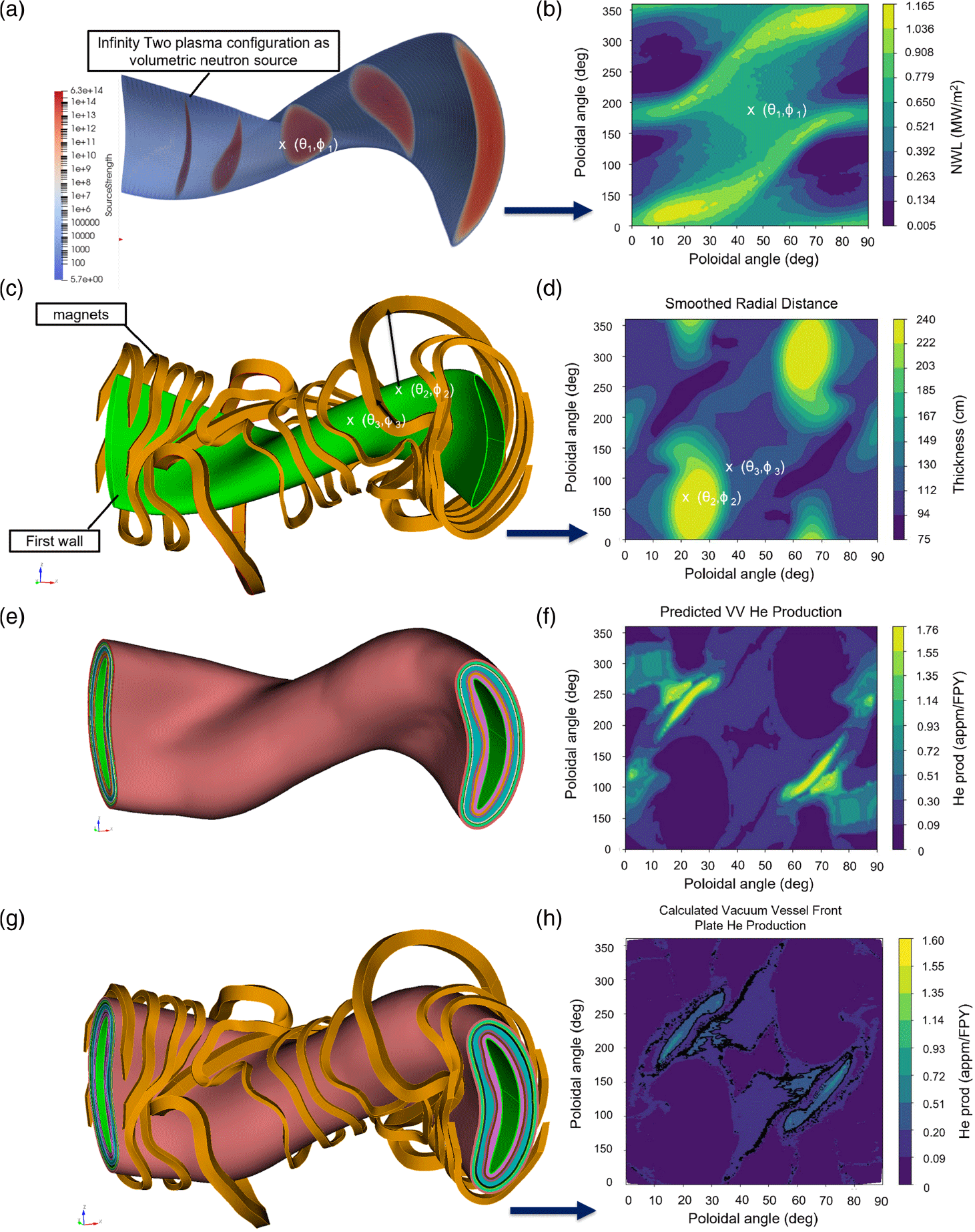
This three-dimensional neutronics analysis made use of ParaStell, which is an open-source python code developed by Moreno et al. (Reference Moreno, Bader and Wilson2024) to automate the parametric computer-aided design (CAD) geometry generation of stellarator blanket structures with uniform thickness given the geometrical definition of the plasma, in this case, the Infinity Two configuration. As part of the workflow for the three-dimensional neutron transport simulations, the first step is to simulate the plasma as a volumetric neutron source with full fidelity of the distribution of DT reaction density in space (figure 3 a). This three-dimensional neutron source is used to derive the two-dimensional spatial distribution of 14.1 MeV neutron flux on the first wall, i.e. neutron wall loading (NWL) (figure 3 b).
It is evident that the radial distance normal from the stellarator first wall to the nearest bounding magnet is not uniform over the field period (figure 3 c). This means that blanket structure thickness can be optimized according to the neutron flux and available space in every radial direction. An optimized blanket build potentially has non-uniform breeder and shield thicknesses. The second step therefore is to obtain a matrix representing the radial distances between the last closed flux surface of the plasma and the magnets (figure 3 d). A proprietary tool was developed for this purpose.
The third step is to optimally allocate the available build space in each radial direction between breeder and shielding material and generate the geometry for every associated layer, as shown in figure 3(e). Figure 3(f) shows the first-order expected neutronic performance on one metric of interest based on this optimization, in this case for example He production by neutron-induced transmutation in the vacuum vessel. This first-order prediction is based on the index of neutronics responses in the relevant blanket build collated from the one-dimensional parametric neutronics study. The one-dimensional radial build configurations for each blanket concept collated are provided in Appendix A.
The blanket layer geometries are then combined with the magnet coil geometries as a full field period of the stellarator geometry (figure 3 g) for full neutronics simulations with OpenMC. Figure 3(h) shows the actual neutronics performance of this geometric model according to the simulation for the same metric – He production in vacuum vessel. The spatial distribution of He-production hotspots predicted in figure 3(f) accurately reflects the distribution obtained in the full simulation.
The radial build space available for the Infinity Two configuration and coil set is shown in figure 3(d), with brighter regions indicating where in toroidal, poloidal space the magnets afford a wider berth for the potential insertion of more breeder or shielding material. The available radial build distance map is dictated only by plasma configuration and coil set, and is therefore independent of the blanket concept. The NWL response matrix (figure 3 b) dictates the net shielding on the magnets required, thereby informing the assignment of breeder, high-temperature shield and low-temperature shield thicknesses constrained by radial build space (figure 3 d). The radial build layers for HCPB are shown in Appendix A, figure 10 and the radial build layers for DCLL are shown in Appendix A, figure 12. The primary difference between the HCPB layers and DCLL layers outside of breeder layer compositions (including breeder material, multiplier and structural materials) and its back wall (abbreviated ‘bw’ in the diagram) are the size of the manifold: the HCPB reference concept was designed for the manifold layer to scale with the breeder layer; the DCLL reference concept was designed for a uniform manifold layer, with radial thickness of 6 cm.
(a) Breeder thickness matrix in ( $\theta$
,
$\theta$
, $\phi$
), HCPB; (b) breeder thickness matrix in (
$\phi$
), HCPB; (b) breeder thickness matrix in ( $\theta$
,
$\theta$
, $\phi$
), DCLL; (c) high-temperature shield thickness matrix in (
$\phi$
), DCLL; (c) high-temperature shield thickness matrix in ( $\theta$
,
$\theta$
, $\phi$
), HCPB; (d) high-temperature shield thickness matrix in (
$\phi$
), HCPB; (d) high-temperature shield thickness matrix in ( $\theta$
,
$\theta$
, $\phi$
), DCLL; (e) low-temperature shield thickness matrix in (
$\phi$
), DCLL; (e) low-temperature shield thickness matrix in ( $\theta$
,
$\theta$
, $\phi$
), HCPB; (f) low-temperature shield thickness matrix in (
$\phi$
), HCPB; (f) low-temperature shield thickness matrix in ( $\theta$
,
$\theta$
, $\phi$
), DCLL; (g) ParaStell geometry generated for HCPB layers; (h) ParaStell geometry generated for DCLL layers.
$\phi$
), DCLL; (g) ParaStell geometry generated for HCPB layers; (h) ParaStell geometry generated for DCLL layers.
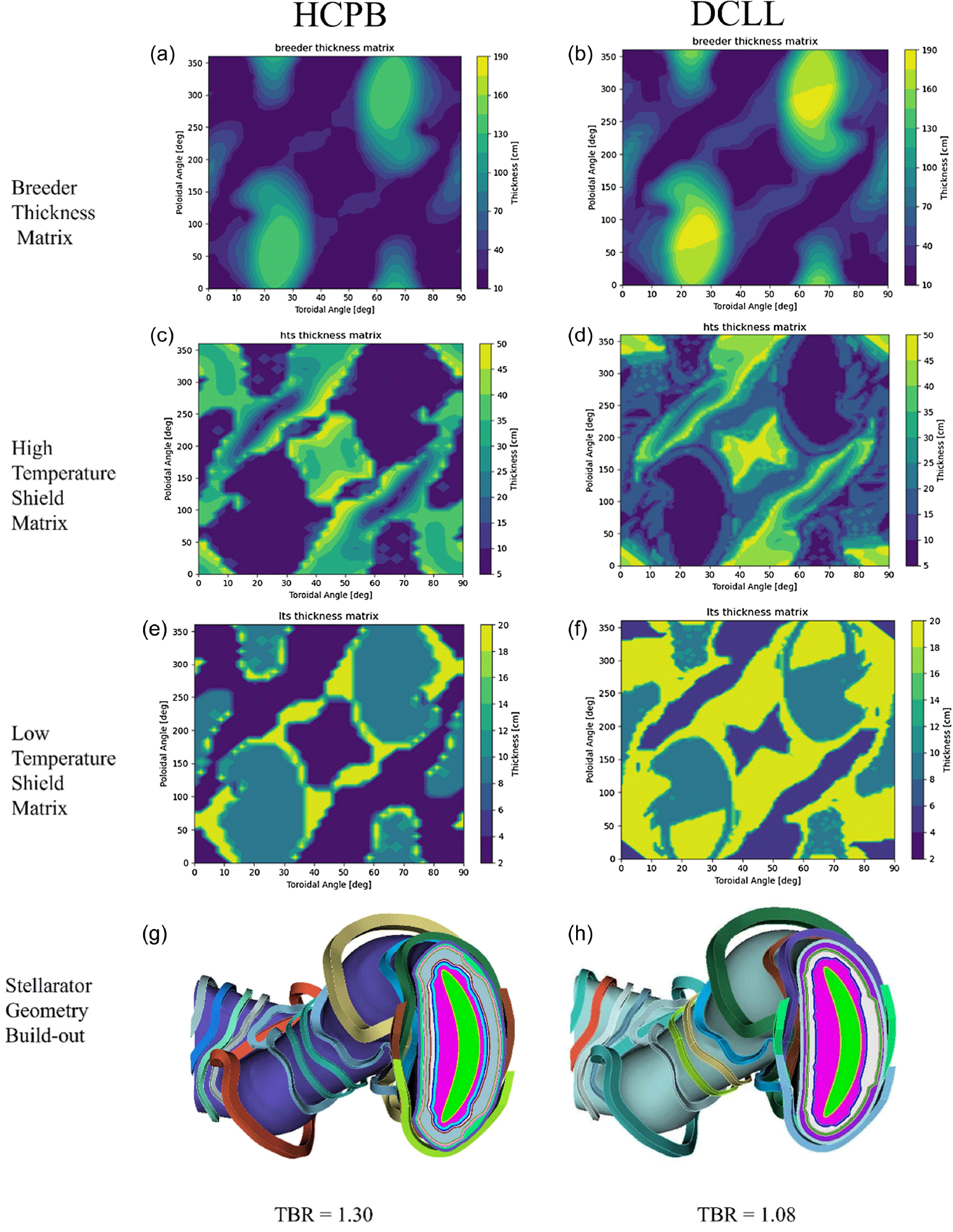
The automated radial build algorithm resulted in the HCPB requiring a much thinner maximum radial build, reflected in the predominance of cooler hues in the color scale plot in the HCPB compared with DCLL, in figures 4(a) and 4(b). The algorithm assigned the HCPB a maximum breeder thickness of 143 cm (figure 4 a) to achieve TBR greater than 1 (unity) compared with the DCLL, which was assigned a maximum breeder thickness of 184 cm (figure 4 b) for similar results, both with comparable shielding. This represents the first major advantage of the HCPB concept over the DCLL concept in that a lower volume of breeder medium is required to achieve a superior TBR. However, it should be noted that the excess balance in the HCPB radial build was not assigned to breeder, high-temperature shield or low-temperature shield and instead was assigned as a manifold layer, which highlights a potential weakness of the HCPB concept which will be further investigated during detailed design activities. The second major advantage of the HCPB concept reflected in the models is that the resulting algorithmic build-out shows a shield design with far fewer contours for the HCPB – which is very desirable for ease of manufacturability – compared with the more DCLL shield design which shows widespread ripple-like contours. This effect is most evident in the high-temperature shields (figures 4 c and 4 d). The required low-temperature shield thickness is lower on average for the HCPB with predominance of cooler colors in the low-temperature shield thickness matrix (figure 4 e) as compared with the one for DCLL (figure 4 f).
The result of this automated buildout is represented by figure 4(g) for HCPB and figure 4(h) for DCLL. The difference in breeder material (pink layer in figures 4 g and 4 h) thickness required for each build for HCPB and DCLL is readily apparent: the DCLL requires a greater breeder material thickness than the HCPB. OpenMC neutronic simulations run with 300 M particles found the TBR for the HCPB case to be 1.30 and the DCLL case to be 1.08. These TBR results are deemed satisfactory at this stage given the level of fidelity as well as the results of § 5 and the various opportunities for continued improvement with subsequent iterations.
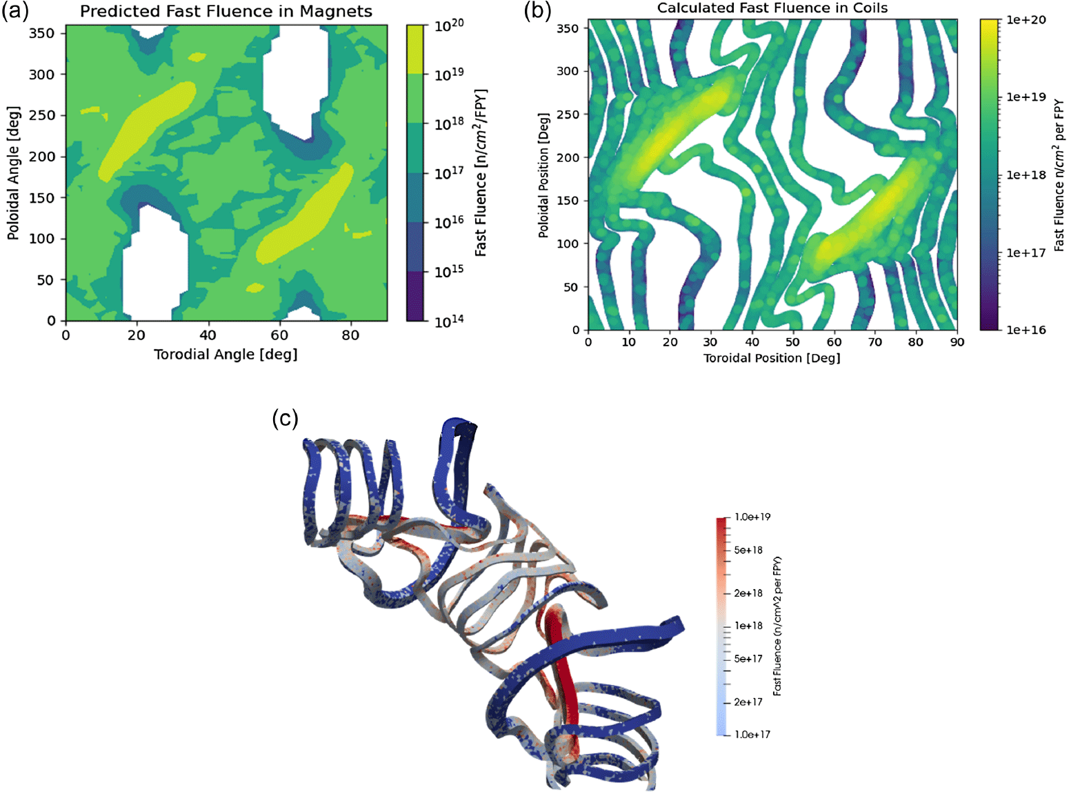
The combination of varying NWL and radial build thickness of the breeder/ shielding layers leads to the expectation that damage primarily occurs in highly localized regions of the various components of interest. The T1E high-throughput workflow enables rapid identification of the presence and location of these high-damage regions for any given plasma–magnet configuration which feeds back into the overall stellarator optimization workflow. To illustrate this point, figure 5(a) shows the mapping of the neutron fluence on the magnet regions in toroidal, poloidal coordinates, which can be rapidly produced without the need for time and computationally intensive three-dimensional neutronics. The blank zones in figure 5(a) reflect regions where predicted neutron fluence is so low that they fall outside the bounds of the developed neutronics response index. Compared with the full stellarator geometry simulation run over seven days on a high-performance computing cluster shown in figure 5(b), the rapid mapping has correctly identified the regions in which the neutron fluence limits are violated at greater than 1 ${\times}$
10
${\times}$
10 $^{18}$
n cm
$^{18}$
n cm $^{-2}$
per full-power year (green and warmer colors) to a first-order level of accuracy. A three-dimensional representation of the spatial distribution of fast neutron fluence on the magnets is shown in figure 5(c). White and blue regions indicate where the fluence on the magnets meet design constraints of less than or equal to
$^{-2}$
per full-power year (green and warmer colors) to a first-order level of accuracy. A three-dimensional representation of the spatial distribution of fast neutron fluence on the magnets is shown in figure 5(c). White and blue regions indicate where the fluence on the magnets meet design constraints of less than or equal to $1 \times 10^{18}$
n cm
$1 \times 10^{18}$
n cm $^{-2}$
per full-power year and red regions indicate where this constraint is violated with greater than 1
$^{-2}$
per full-power year and red regions indicate where this constraint is violated with greater than 1 ${\times}$
10
${\times}$
10 $^{18}$
n cm
$^{18}$
n cm $^{-2}$
per full-power year. Figure 5(c) generally reflects that hotspots are predicted mostly on the inboard side.
$^{-2}$
per full-power year. Figure 5(c) generally reflects that hotspots are predicted mostly on the inboard side.
(a) Two-dimensional spatial distribution of neutron fluence per full-power year at magnet locations in ( $\theta$
,
$\theta$
, $\phi$
) predicted based on neutronics response index generated from the rapid optimization workflow step 2 for HCPB radial build configuration. (b) Two-dimensional spatial distribution of neutron fluence per full-power year at magnet locations in (
$\phi$
) predicted based on neutronics response index generated from the rapid optimization workflow step 2 for HCPB radial build configuration. (b) Two-dimensional spatial distribution of neutron fluence per full-power year at magnet locations in ( $\theta$
,
$\theta$
, $\phi$
) based on full stellarator geometry simulation of HCPB radial build configuration. (c) Three-dimensional representation of space-resolved neutron fluence per full-power year on stellarator magnets based on full stellarator geometry simulation of HCPB radial build configuration.
$\phi$
) based on full stellarator geometry simulation of HCPB radial build configuration. (c) Three-dimensional representation of space-resolved neutron fluence per full-power year on stellarator magnets based on full stellarator geometry simulation of HCPB radial build configuration.
At this juncture, it must be emphasized that the results presented here are for a simplified neutronics model of an early design iteration and do not constitute a final, optimized radial build at full engineering fidelity. The current radial build model is a high-level placeholder for use in an initial scoping analysis, and it will be refined to incorporate opportunities for reduced component volumes and increased shielding performance moving forward. In addition, the radiation limits on lifetime components are dependent on design and in some cases are not based on quantities which are well understood, such as the radiation limits on high-temperature superconducting magnets (Unterrainer et al. Reference Unterrainer, Fischer, Lorenz and Eisterer2022). As such, they are subject to modification as both fundamental understanding and design fidelity improves. Given these points, the current findings show that the Infinity Two configuration has sufficient performance and no fundamental roadblocks exist towards the continued optimization of radial builds which will satisfy detailed performance and engineering requirements.
4. Thermal analysis
4.1. Introduction
This section presents a sensitivity analysis of the various blanket concepts and their possible integration with a Rankine thermodynamic cycle, which was selected as the baseline due in large part to its robust industrial base and existing supply chain. The primary focus of this study was to understand the potential of each concept for producing at least 100 MW $_{e}$
as a nominal minimum target for Infinity Two. To ensure flexibility in design space and allow operation over a range of fusion plasma power, a fusion plasma power of 400 MW
$_{e}$
as a nominal minimum target for Infinity Two. To ensure flexibility in design space and allow operation over a range of fusion plasma power, a fusion plasma power of 400 MW $_{\mathrm{th}}$
was used as the low-end baseline for evaluating this performance. The scalability of these results was also explored for designs up to 1000 MW
$_{\mathrm{th}}$
was used as the low-end baseline for evaluating this performance. The scalability of these results was also explored for designs up to 1000 MW $_{\mathrm{th}}$
of fusion plasma power. The blanket concepts and baseline design parameters evaluated in this study are listed in table 4.
$_{\mathrm{th}}$
of fusion plasma power. The blanket concepts and baseline design parameters evaluated in this study are listed in table 4.
Summarized thermal parameters for blanket concepts under consideration.
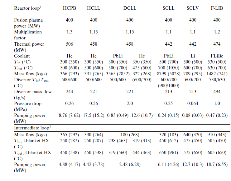
1 Values in each cell are for the basic concepts. Values in parentheses are for the advanced concepts.
In an MFE energy system, heat is distributed throughout the power core and high-grade heat sources typically include the blanket, the divertor and potentially the vacuum vessel, depending on design. For this analysis, only the blanket and divertor were considered as heat sources, with the assumption that all heat not directed at the divertor (conservatively assumed to be 25 %) is instead deposited in the blanket. In the case of the F-LIB concept, the internal vacuum vessel is cooled with molten salt which is discharged directly into the blanket and keeps in convention with this same assumption. In addition to the heat being deposited in the blanket, each concept has an additional neutron energy multiplication factor, which for the purposes of this study were assumed to be the same as those developed by El-Guebaly et al. (Reference El-Guebaly, Raffray, Malang, Lyon and Ku2005). This energy multiplication factor results in a different total thermal power for each blanket concept, assuming a standard fusion plasma power.
The pressure drops shown in table 4 are based on values found in the literature for each reference design (Sagara et al. Reference Sagara1997; Gohar et al. Reference Gohar, Majumdar and Smith2000; Giancarli et al. Reference Giancarli, Golfier, Nishio, Raffray, Wong and Yamada2002; Hernández et al. Reference Hernández, Pereslavtsev, Kang, Norajitra, Kiss, Nádasi and Bitz2017; Aubert et al. Reference Aubert2018; Smolentsev et al. Reference Smolentsev, Rhodes, Pulugundla, Courtessole, Abdou, Malang, Tillack and Kessel2018). The pumping power of each blanket concept was then calculated using the mass flow rate of the blanket and divertor using the assumed pressure drop from the literature. An isentropic efficiency of 100 % was assumed for all pumps/compressors used in the blanket loop given the variety of coolants used. Since the pressure drop is highly dependent on design specifics, it was varied parametrically to calculate the required pumping power and thus efficiency of each concept in this analysis across a range of potential values. Similarly, the operating temperatures, both high end and low end, are primarily dictated by the structural material of choice and compatibility with applicable coolants (Zinkle & Ghoniem Reference Zinkle and Ghoniem2000). In the case of the DCLL, the helium temperature range is not consistent throughout literature. For this reason, the helium temperature range in the DCLL was based on a similar temperature change but within the temperature range used in the references. The initial temperature ranges, as well as associated parameters like mass flow and pumping power, are shown in table 4 and are based on the baseline assumption for structural materials. If advanced materials become available, it is possible to broaden the temperature window of all the blankets concepts to improve overall performance (Zinkle & Ghoniem Reference Zinkle and Ghoniem2000). The second value in columns with multiple values in table 4 shows the parameters associated with designs which use these advanced materials. One point of note is that the SCLL only has an advanced design utilizing SiC composites, but in order to provide an additional comparison point between concepts a lower-temperature SCLL was run consistent with the SCLV advanced parameters, which are the values shown for the SCLL baseline configuration in table 4.
For this analysis, an intermediate heat transfer system using He was implemented between the primary loop and the Rankine cycle loop for all blanket concepts. The parameters for these intermediate loops are shown in the intermediate loop section of table 4. The intermediate loop serves as a barrier separating the water in the Rankine loop from the breeder in the blanket loop, which may contain tritium and liquid lithium-based coolants, depending on the concept. These liquid lithium-based coolants can have strong reactions to water at elevated temperatures, which could potentially lead to exothermic reactions and/or explosivity, and the intermediate loop helps to prevent such interactions. It also helps to avoid the creation of tritiated water. Both phenomena have safety and economic implications and for these reasons, gaseous, relatively inert coolants like He or CO $_{2}$
are considered for the intermediate loop. Other types of coolants such as molten salts have been considered for the same reasons above, with the benefit of serving in a thermal storage capacity which is important for pulsed concepts such as the tokamak (Barucca et al. Reference Barucca2021). Some concepts like the HCPB do not necessarily require an intermediate loop, but an intermediate loop was assumed as a baseline for all concepts to better compare performance under equitable conditions. An analysis without an intermediate loop was also performed for the relevant concepts and is discussed further in § 4.3.
$_{2}$
are considered for the intermediate loop. Other types of coolants such as molten salts have been considered for the same reasons above, with the benefit of serving in a thermal storage capacity which is important for pulsed concepts such as the tokamak (Barucca et al. Reference Barucca2021). Some concepts like the HCPB do not necessarily require an intermediate loop, but an intermediate loop was assumed as a baseline for all concepts to better compare performance under equitable conditions. An analysis without an intermediate loop was also performed for the relevant concepts and is discussed further in § 4.3.
For the power loop, a Rankine cycle with reheat was analyzed. The temperature-entropy (T-S) diagram and the cycle configuration are shown in figure 17 in Appendix A. In this configuration, the blanket heat is deposited in the intermediate loop and used to create superheated steam in the Rankine cycle loop. The divertor heat is used to reheat the steam in the Rankine side. A temperature difference of 100 $^\circ$
C between the maximum intermediate loop temperature and the inlet turbine temperature was assumed. Other assumptions include an isentropic efficiency of 0.85 for both the pump and the turbine. The steam quality at the turbine outlet was set to 0.90 for the lower-temperature end pressure cycles and to 0.99 for the higher-temperature end pressure cycles. A pressure drop of 0.5 MPa was used for every heat exchanger. Recirculating power for auxiliary systems, plasma heating and other sources of pressure drop apart from the pressure drop in the blanket loop were not considered in the analysis.
$^\circ$
C between the maximum intermediate loop temperature and the inlet turbine temperature was assumed. Other assumptions include an isentropic efficiency of 0.85 for both the pump and the turbine. The steam quality at the turbine outlet was set to 0.90 for the lower-temperature end pressure cycles and to 0.99 for the higher-temperature end pressure cycles. A pressure drop of 0.5 MPa was used for every heat exchanger. Recirculating power for auxiliary systems, plasma heating and other sources of pressure drop apart from the pressure drop in the blanket loop were not considered in the analysis.
A python script was developed to perform the parametric analysis capable of calculating how the mass flow rate, net power and efficiency changed with varying conditions like blanket pressure drop, fusion power, steam quality, etc. using the energy balance equation. The IAPWS R 7–97(2012) python module was used to calculate all the thermodynamic states of steam in the Rankine cycle loop. The module requires two initial parameters (pressure, temperature, entropy, enthalpy or steam quality) to return the remaining thermodynamic parameters needed.
4.2. Intermediate loop and blanket pressure drop analysis
An analysis of the primary blanket heat exchanger between the blanket and the intermediate loop was performed to understand performance discrepancies between concepts. The outlet temperature of the blanket/intermediate heat exchanger shown in table 4 was calculated using the effectiveness-number of transfer units ( $\epsilon$
-NTUs) method. As shown in table 4, the DCLL blanket requires the smallest intermediate coolant mass flow rate due to the usage of dual coolants and heat exchangers for the transfer of heat to the intermediate loop. Since the heat is divided across two different coolants (46 % of the heat removed by He and the rest by PbLi (Wang et al. Reference Wang, Tillack, Koehly, Malang, Toudeshki and Najmabadi2015)), the heat capacity rate of the PbLi is the smallest out of all the analyzed designs, meaning that it is more suitable for transferring heat. The end result is that less intermediate coolant is needed to extract heat in the PbLi heat exchanger. The He heat exchanger is then used to further heat the intermediate coolant after the PbLi heat exchanger. Although the SCLL is also cooled by PbLi, its blanket mass flow rate is almost double that of the DCLL resulting in a higher heat capacity rate than the DCLL. As a result, the SCLL requires approximately twice as much intermediate coolant as the DCLL. The HCPB, HCLL and SCLL all have similar heat capacity rates leading to similar intermediate coolant mass flow rates. In contrast, the SCLV and FLiBe blanket will require the largest intermediate loop, as they need the most intermediate coolant due to their higher heat capacity rate.
$\epsilon$
-NTUs) method. As shown in table 4, the DCLL blanket requires the smallest intermediate coolant mass flow rate due to the usage of dual coolants and heat exchangers for the transfer of heat to the intermediate loop. Since the heat is divided across two different coolants (46 % of the heat removed by He and the rest by PbLi (Wang et al. Reference Wang, Tillack, Koehly, Malang, Toudeshki and Najmabadi2015)), the heat capacity rate of the PbLi is the smallest out of all the analyzed designs, meaning that it is more suitable for transferring heat. The end result is that less intermediate coolant is needed to extract heat in the PbLi heat exchanger. The He heat exchanger is then used to further heat the intermediate coolant after the PbLi heat exchanger. Although the SCLL is also cooled by PbLi, its blanket mass flow rate is almost double that of the DCLL resulting in a higher heat capacity rate than the DCLL. As a result, the SCLL requires approximately twice as much intermediate coolant as the DCLL. The HCPB, HCLL and SCLL all have similar heat capacity rates leading to similar intermediate coolant mass flow rates. In contrast, the SCLV and FLiBe blanket will require the largest intermediate loop, as they need the most intermediate coolant due to their higher heat capacity rate.
In addition to the intermediate loop, one of the main factors that affects net power is the power required to pump the coolant through the blanket, which is an identified challenge for fusion power devices and has been a subject of study (Sagara et al. Reference Sagara1997; Gohar et al. Reference Gohar, Majumdar and Smith2000; Giancarli et al. Reference Giancarli, Golfier, Nishio, Raffray, Wong and Yamada2002; Hernández et al. Reference Hernández, Pereslavtsev, Kang, Norajitra, Kiss, Nádasi and Bitz2017; Smolentsev et al. Reference Smolentsev, Rhodes, Pulugundla, Courtessole, Abdou, Malang, Tillack and Kessel2018; Aubert et al. Reference Aubert2018). Specifically, MHD effects are one of the biggest factors to consider in liquid metals since it can induce a significant pressure drop in high-field MFE systems, and it remains a phenomenon that is not well understood (Smolentsev Reference Smolentsev2021). Given that the pressure drop in a stellarator may be highly configuration dependent, the pressure drop was varied when calculating the pumping power, with the purpose of comparing blanket designs and its potential impact on overall system efficiency. The pressure drop range was chosen with the recognition that the total pressure drop in the primary blanket loop is not limited to just the pressure drop in the blanket, and that ancillary equipment, including the tritium extraction system and the primary coolant/intermediate heat exchanger may contribute to a larger aggregate pressure drop. According to Smolentsev et al. (Reference Smolentsev, Rhodes, Pulugundla, Courtessole, Abdou, Malang, Tillack and Kessel2018), this pressure drop could be comparable to or even exceed the MHD pressure drop in a DCLL blanket, with rough estimates suggesting that the sum of individual pressure drops in the ancillary system could be up to approximately 2 MPa. The pressure drop range explored in this analysis was between 0.05 and 4 MPa for all the blanket concepts. This broad range represents reasonable limits on allowable pumping power for the liquid-cooled concepts. It should be noted that the allowable pressure drop limits for He are much narrower than for the liquid concepts. The pumping power was calculated using density for the liquids, which were assumed to be incompressible, and enthalpies for He.
A comparison of pumping power for the baseline blanket concepts can be seen in figure 6(a). The results show that the He-cooled blankets both require the highest pumping power and are more sensitive to pressure drops. Even though both the HCPB and HCLL blankets have the same coolant and coolant temperatures, the HCPB has higher pumping power than the HCLL due to its higher energy multiplication factor, which results in higher thermal power and subsequently a higher mass flow rate and associated pumping power. For the DCLL, only the pumping power of PbLi was varied, and a constant pressure drop of 0.39 MPa was assumed for He (Melichar et al. Reference Melichar, Frýbort, Vála, Zácha, Fernández and Rapisarda2017). The pumping power of He was calculated using this pressure drop and added to the pumping power of PbLi in order to calculate the total pressure drop for the DCLL concept. Results show that the DCLL concept requires the most pumping power out of all the non-He-only blankets, due to the relatively large pumping power required for He.
Pumping power comparison for the (a) basic concepts and (b) advanced concepts.
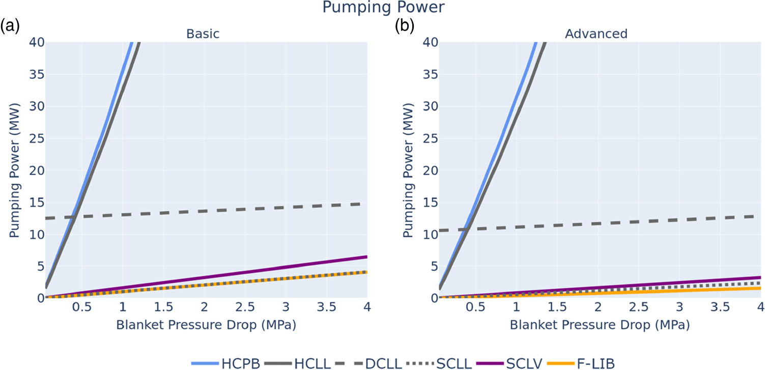
A comparison of pumping powers for the advanced blanket concepts with expanded operating temperatures can be seen in figure 6(b). Increasing the temperature range reduces mass flow rate by a factor of approximately two for all the blanket concepts, which results in an analogous drop in pumping power. The advanced He-cooled blankets are still the most sensitive to pressure drop, and the DCLL requires the highest pumping power compared with the other non-He blankets. The SCLV and the SCLL have similar pumping powers, and F-LIB requires the least pumping power, consistent with the basic designs. It should be noted that the assumed pressure drops stayed constant across the analysis of both the basic and advanced designs. However, because the coolant velocities and temperature differences shift rather substantially compared with the basic blanket concepts, it is expected that different pressure drops will vary between concepts. This discrepancy in pressure drop was not accounted for in this study and requires further analysis in future work. Finally, it should be noted that even the highest pumping power values shown in figure 6 are below 5 % of the total power for the liquid-cooled blanket concepts, which is a general limit on targeted pumping power percentage presented in the literature and the one used for this analysis. For the helium-cooled blankets (HCPB and HCLL) a pumping power of less than 5 % total power is achieved with a pressure drop of less than 0.77 MPa.
4.3. Power cycle sensitivity analysis
Figure 7 shows the net power and efficiency results for the reheat cycles of the various blanket concepts, with the individual designs shown in table 5. Figure 7(b) indicates that all of the basic blanket concepts can achieve efficiencies higher than 30 % so long as the primary loop pressure drops are kept below the most extreme values. For the HCPB and HCLL, 30 % efficiency is obtained when the pressure drop is below 0.24 MPa. The SCLL blanket concept is the only basic concept which achieves efficiency greater than 40 %, while the SCLV and F-LIB achieve efficiencies in the range of 35 %–40 %. The three low-temperature concepts all have efficiencies in the range of 30 %–35 % due to the utilization of similar, lower operating temperature structural materials, as well as He coolant, which results in comparable pumping powers. Of the three, the HCPB achieves the highest net power due to its higher energy multiplication factor in the blanket. When an intermediate loop is not included for the baseline HCPB and HCLL, both the net power and the efficiency increase by approximately 10 %. This is due to the net pumping power being significantly lower, as the intermediate loop requires a relatively high He mass flow rate and additional heat exchangers which lead to pressure drop, resulting in non-trivial additional pumping power. In addition, the elimination of the intermediate loop allows for higher inlet turbine temperatures in the Rankine cycle, which boosts efficiency.
Summarized parameters of Rankine cycle loop with reheat assuming the pressure drop from table 4.
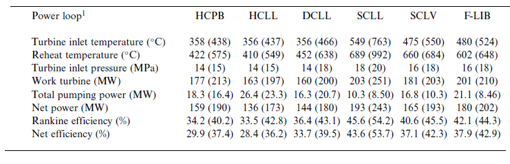
1 Values in each cell are for the basic concepts. Values in parentheses are for the advanced concepts.
(a) Net power with respect to pressure drop for basic concepts, (b) net efficiency with respect to pressure drop for basic concepts, (c) net power with respect to pressure drop for advanced concepts and (d) net efficiency with respect to pressure drop for advanced concepts.
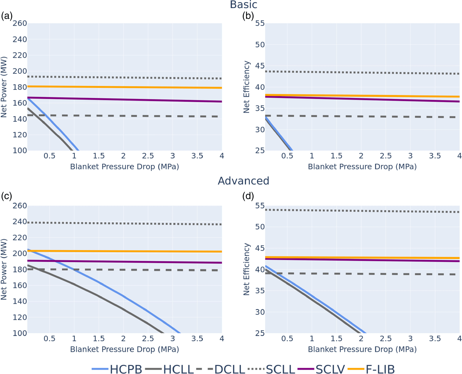
The net power and efficiency for the advanced blanket concepts were also analyzed and the results, indicated in the parentheses, can be found in table 5 as well as illustrated in figures 7(c) and 7(d)
. With the advanced concepts, both the outlet temperature and temperature difference are higher. As shown in the pressure drop analysis, having a higher temperature difference leads to a lower mass flow rate for a given fusion power, resulting in a lower pressure drop curve. As expected, the net power and efficiency increase rather significantly for all concepts. The efficiency of the lower-temperature blankets (HCPB, HCLL, DCLL) increased by 7 %. The SCLV and F-LIB concepts also benefited from the higher blanket temperatures to increase their efficiency by approximately 5 %. Lastly, the SCLL benefited the most from the higher blanket temperatures (1050 $^\circ$
C) by increasing its efficiency to approximately 50 %. Under these conditions, all of these blanket concepts easily achieve the initial objective of producing 100 MW
$^\circ$
C) by increasing its efficiency to approximately 50 %. Under these conditions, all of these blanket concepts easily achieve the initial objective of producing 100 MW $_{e}$
. In the case that an intermediate loop is not included for the baseline HCPB and HCLL, both the net power and the efficiency increase by approximately 10 % as in the base cases.
$_{e}$
. In the case that an intermediate loop is not included for the baseline HCPB and HCLL, both the net power and the efficiency increase by approximately 10 % as in the base cases.
4.4. Infinity Two point design
If the fusion power needs to be increased, the thermal performance of the blanket concepts and associated Rankine cycle remains practically unchanged assuming the same temperatures, temperature differences and pressures are used. Although the overall pumping power increases due to a higher mass flow rate requirement, this is balanced by a higher turbine output. These factors offset each other, resulting in similar net efficiency, while net power increases with higher fusion power. Table 6 presents the results of the Rankine cycle analysis for the Infinity Two point design with a fusion plasma power of 800 MW $_{\mathrm{th}}$
using an HCPB with reheat and no intermediate loop. A four corners approach employed by the ARIES system study program (Kessel et al. Reference Kessel2015) was used to explore the potential range of power outputs and efficiencies for the thermal cycle. In this analysis, the base case assumed that recirculating power requirements are primarily driven by the thermal system, with a total pumping power requirement of 49.61 MW (5 % of the thermal power). The steady-state plasma heating and recirculating power for other systems such as the cryogenic and TFC plants were assumed to be negligible. From this, it can be concluded that a net efficiency of at least 30 % is readily achievable using a Rankine cycle and reasonable margins exist for accommodating uncertainties moving forward into the design. In addition, opportunities for improvement also exist, including improvements in blanket/primary loop design to reduce pumping power requirements, utilization of advanced materials for larger temperature windows and ultimate upper end temperature limits, and detailed design of the Rankine cycle to employ reheaters/preheaters and advantageous allocation of the steam flow rates. In addition, Brayton cycles will also be explored as FusionDirect develops to assess opportunities for continued improvements in thermal efficiency (Syblik et al. Reference Syblik, Vesely, Entler, Stepanek and Dostal2019). Key uncertainties include pressure drops based on higher fidelity engineering designs, as well as recirculating power requirements for the other support systems in the plant. These will be the subject of future work.
$_{\mathrm{th}}$
using an HCPB with reheat and no intermediate loop. A four corners approach employed by the ARIES system study program (Kessel et al. Reference Kessel2015) was used to explore the potential range of power outputs and efficiencies for the thermal cycle. In this analysis, the base case assumed that recirculating power requirements are primarily driven by the thermal system, with a total pumping power requirement of 49.61 MW (5 % of the thermal power). The steady-state plasma heating and recirculating power for other systems such as the cryogenic and TFC plants were assumed to be negligible. From this, it can be concluded that a net efficiency of at least 30 % is readily achievable using a Rankine cycle and reasonable margins exist for accommodating uncertainties moving forward into the design. In addition, opportunities for improvement also exist, including improvements in blanket/primary loop design to reduce pumping power requirements, utilization of advanced materials for larger temperature windows and ultimate upper end temperature limits, and detailed design of the Rankine cycle to employ reheaters/preheaters and advantageous allocation of the steam flow rates. In addition, Brayton cycles will also be explored as FusionDirect develops to assess opportunities for continued improvements in thermal efficiency (Syblik et al. Reference Syblik, Vesely, Entler, Stepanek and Dostal2019). Key uncertainties include pressure drops based on higher fidelity engineering designs, as well as recirculating power requirements for the other support systems in the plant. These will be the subject of future work.
Rankine cycle four corner analysis.
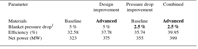
1 Percent of thermal power using baseline parameters.
5. Tritium fuel cycle analysis
5.1. Introduction
Following the work of Abdou et al. (Reference Abdou, Riva, Ying, Day, Loarte, Baylor, Humrickhouse, Fuerst and Cho2021) and Meschini et al. (Reference Meschini, Ferry, Delaporte-Mathurin and Whyte2023), a series of dynamic system-level models based on the RTM were developed for the TFC and applied to a relevant space of interest to understand the implications of various system and technology choices. In the RTM, the TFC is represented by a high-level model with constant flow rates in and out of each component, which can be described by zero-dimensional time-dependent ordinary differential equations. For the sake of simplicity, flexibility, speed and computational resource requirements, no detailed physics modeling of each component was performed. Some of the key system-level parameters examined in this study include fusion plasma power ( $P_{f}$
), plant availability factor (AF), tritium burn efficiency (TBE), direct internal recycling fraction (DIR), reserve time (
$P_{f}$
), plant availability factor (AF), tritium burn efficiency (TBE), direct internal recycling fraction (DIR), reserve time ( $t_{r}$
), doubling time (
$t_{r}$
), doubling time ( $t_{d}$
), breeding zone (BZ) resident time (
$t_{d}$
), breeding zone (BZ) resident time ( $\tau _{\mathrm{BZ}}$
), tritium extraction system (TES) efficiency (
$\tau _{\mathrm{BZ}}$
), tritium extraction system (TES) efficiency ( $\eta _{\mathrm{TES}}$
), coolant purification system (CPS) efficiency (
$\eta _{\mathrm{TES}}$
), coolant purification system (CPS) efficiency ( $\eta _{\mathrm{CPS}}$
), tritium start-up inventory (
$\eta _{\mathrm{CPS}}$
), tritium start-up inventory ( $I_{0}$
), operational inventory (
$I_{0}$
), operational inventory ( $I_{\mathrm{operational}}$
) and required tritium breeding ratio (
$I_{\mathrm{operational}}$
) and required tritium breeding ratio ( $\mathrm{TBR}_{\mathrm{req}}$
). It is important to note that
$\mathrm{TBR}_{\mathrm{req}}$
). It is important to note that $\mathrm{TBR}_{\mathrm{req}}$
is not the same as the TBR referenced in § 3, but is instead the minimum TBR target which is required to meet a prescribed doubling time for a specific TFC architecture. For additional discussion of the RTM model, including a description of specific subsystems, components, technology options, mathematical formulation and system-level parameters, readers are referred to Abdou et al. (Reference Abdou, Riva, Ying, Day, Loarte, Baylor, Humrickhouse, Fuerst and Cho2021) and Meschini et al. (Reference Meschini, Ferry, Delaporte-Mathurin and Whyte2023).
$\mathrm{TBR}_{\mathrm{req}}$
is not the same as the TBR referenced in § 3, but is instead the minimum TBR target which is required to meet a prescribed doubling time for a specific TFC architecture. For additional discussion of the RTM model, including a description of specific subsystems, components, technology options, mathematical formulation and system-level parameters, readers are referred to Abdou et al. (Reference Abdou, Riva, Ying, Day, Loarte, Baylor, Humrickhouse, Fuerst and Cho2021) and Meschini et al. (Reference Meschini, Ferry, Delaporte-Mathurin and Whyte2023).
In addition to the system-level parameters above which have been examined in previous studies, several new blanket specific parameters were identified and examined as potential drivers of the overall TFC dynamics.
-
(i) Tritium loss fraction in the blanket ( $\epsilon _{\mathrm{BZ}}$
) assuming that tritium may permeate into and become sequestered in structural or functional materials in vessel, which has been identified as a potential issue both from a feasibility and safety perspective (Zinkle et al. Reference Zinkle, Möslang, Muroga and Tanigawa2013).
$\epsilon _{\mathrm{BZ}}$
) assuming that tritium may permeate into and become sequestered in structural or functional materials in vessel, which has been identified as a potential issue both from a feasibility and safety perspective (Zinkle et al. Reference Zinkle, Möslang, Muroga and Tanigawa2013). -
(ii) Tritium flow fraction from the heat exchanger to the detritiation system (
$f_{\mathrm{HX}\rightarrow \mathrm{detritiation}}$
), which describes the fraction of tritium that permeates through the blanket side of the heat exchanger wall into a sweep gas, assuming a heat exchanger with an active tritium removal system, which is then fed to the water detritiation system. -
(iii) Tritium direct blanket processing fraction (DBP) for blanket tritium removal. The DBP has been explored in various fuel cycle designs (Meschini et al. Reference Meschini, Ferry, Delaporte-Mathurin and Whyte2023) but never systematically investigated. Similar to DIR, the purpose of DBP is to carry a fraction of the bred fuel directly from the TES to the storage and management system, thus bypassing the isotope separation system and shortening processing times.
-
(iv) TES bypass fraction (
$f_{\mathrm{BZ}\rightarrow \mathrm{HX}}$
), which describes a design parameter whereby a fraction of tritium containing breeding medium/coolant bypasses the TES and is instead diverted directly to the heat exchanger. This may be advantageous for dual or self-cooled systems for thermal conversion efficiency reasons.


5.2. Parametric TFC analysis
The purpose of this initial application of the RTM was to understand at a high level the implication of different design choices on the TFC of high-field stellarator configurations. The three different TFCs used in this portion of the analysis are shown in Appendix A, figure 16, building on prior work (Abdou et al. Reference Abdou, Riva, Ying, Day, Loarte, Baylor, Humrickhouse, Fuerst and Cho2021; Meschini et al. Reference Meschini, Ferry, Delaporte-Mathurin and Whyte2023). Only the components that have been modeled are shown in the figure and the inner fuel cycle (IFC) remained unchanged between blanket systems. The IFC layout used in this analysis was the same as Abdou et al. (Reference Abdou, Riva, Ying, Day, Loarte, Baylor, Humrickhouse, Fuerst and Cho2021), which utilized a more conservative definition of DIR. For the outer fuel cycle (OFC), three general layouts were developed consistent with the various types of fluid flows from the blanket, which is dictated by the usage of both separate cooling and self-cooling.
The analysis itself used a simple but effective approach known as the one-at-a-time sensitivity analysis (Hamby Reference Hamby1994), which has been used to great effect for analyzing TFC sensitivities for a EUROfusion DEMO-like device (Abdou et al. Reference Abdou, Riva, Ying, Day, Loarte, Baylor, Humrickhouse, Fuerst and Cho2021), Commonwealth Fusion System’s Affordable, Robust, Compact (ARC)-class device and the UKAEA’s Spherical Tokamak for Energy Production device (Meschini et al. Reference Meschini, Ferry, Delaporte-Mathurin and Whyte2023). Table 7 lists the parameters and the range of values considered in this study, with table 8 listing the blanket design specific values, as well as resulting inventories and $\mathrm{TBR}_{\mathrm{req}}$
for each of the seven blanket designs base cases.
$\mathrm{TBR}_{\mathrm{req}}$
for each of the seven blanket designs base cases.
Fuel cycle parameters employed for the parametric analysis.
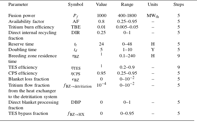
1 These values vary by blanket concept as shown in table 8.
Blanket specific parameters, base case inventories, and $\mathrm{TBR}_{\mathrm{req}}$
for the seven blanket concepts evaluated in the parametric analysis.
$\mathrm{TBR}_{\mathrm{req}}$
for the seven blanket concepts evaluated in the parametric analysis.
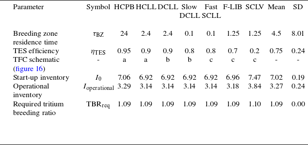
From table 8, it can be inferred that the choice of blanket is not a strong driver of either inventory or breeding requirements given the chosen system-level parameters. The only discernible difference is driven by the modest increase in operational inventory of the OFC for the HCPB and SCLV. In order to better quantify sensitivities beyond a single data point for each concept, the approach of determining relative sensitivity utilized by Meschini et al. (Reference Meschini, Ferry, Delaporte-Mathurin and Whyte2023) was employed. In this approach, a relative sensitivity index coefficient (RIC) is calculated for each parameter in order to identify the relative importance of each. The mean RIC for each of the thirteen parameters is shown in figure 8(a), with radar plots showing the deviation of each blanket concept with respect to the mean in figure 8(b–d).
As can be seen, the main drivers of $I_{0}$
are TBE,
$I_{0}$
are TBE, $P_{f}$
,
$P_{f}$
, $t_{r}$
and DIR;
$t_{r}$
and DIR; $I_{\mathrm{operational}}$
shares three of the same drivers (TBE,
$I_{\mathrm{operational}}$
shares three of the same drivers (TBE, $P_{f}$
and DIR) but is largely independent of
$P_{f}$
and DIR) but is largely independent of $t_{r}$
. In its place, it is more dependent on
$t_{r}$
. In its place, it is more dependent on $\tau _{\mathrm{BZ}}$
and
$\tau _{\mathrm{BZ}}$
and $\eta _{\mathrm{TES}}$
, which dictates operational inventory in the blanket;
$\eta _{\mathrm{TES}}$
, which dictates operational inventory in the blanket; $\mathrm{TBR}_{\mathrm{req}}$
is independently driven by AF and
$\mathrm{TBR}_{\mathrm{req}}$
is independently driven by AF and $t_{d}$
which impacts breeding requirements directly;
$t_{d}$
which impacts breeding requirements directly; $\mathrm{TBR}_{\mathrm{req}}$
is also driven indirectly by TBE,
$\mathrm{TBR}_{\mathrm{req}}$
is also driven indirectly by TBE, $t_{r}$
and DIR through their impact on
$t_{r}$
and DIR through their impact on $I_{0}$
, which requires a corresponding shift in
$I_{0}$
, which requires a corresponding shift in $\mathrm{TBR}_{\mathrm{req}}$
to maintain a prescribed
$\mathrm{TBR}_{\mathrm{req}}$
to maintain a prescribed $t_{d}$
;
$t_{d}$
; $\mathrm{TBR}_{\mathrm{req}}$
is largely independent of
$\mathrm{TBR}_{\mathrm{req}}$
is largely independent of $P_{f}$
, even though both
$P_{f}$
, even though both $I_{0}$
and
$I_{0}$
and $I_{\mathrm{operational}}$
have a relatively high dependency on this parameter. This is due to the net increase in neutron production with increasing
$I_{\mathrm{operational}}$
have a relatively high dependency on this parameter. This is due to the net increase in neutron production with increasing $P_{f}$
, thus keeping
$P_{f}$
, thus keeping $\mathrm{TBR}_{\mathrm{req}}$
largely unchanged. Given the relatively low TBE and DIR of the assumed reference case, the inventory in the IFC dominates the overall system and the parameters which dictate that inventory (TBE,
$\mathrm{TBR}_{\mathrm{req}}$
largely unchanged. Given the relatively low TBE and DIR of the assumed reference case, the inventory in the IFC dominates the overall system and the parameters which dictate that inventory (TBE, $P_{f}$
,
$P_{f}$
, $t_{r}$
and DIR) dominate the overall dynamics of the system. The implications of this can be seen with DBP which has essentially no relevancy on the overall system dynamics, whereas the analogous DIR is a key parameter. For this analysis there were no parameters for which the RIC had both a significant value and difference in sign between
$t_{r}$
and DIR) dominate the overall dynamics of the system. The implications of this can be seen with DBP which has essentially no relevancy on the overall system dynamics, whereas the analogous DIR is a key parameter. For this analysis there were no parameters for which the RIC had both a significant value and difference in sign between $I_{0}$
,
$I_{0}$
, $I_{\mathrm{operational}}$
or
$I_{\mathrm{operational}}$
or $\mathrm{TBR}_{\mathrm{req}}$
. This implies that an overall system can be designed which optimizes (i.e. minimizes) all three parameters simultaneously without the need for significant tradeoffs.
$\mathrm{TBR}_{\mathrm{req}}$
. This implies that an overall system can be designed which optimizes (i.e. minimizes) all three parameters simultaneously without the need for significant tradeoffs.
Figure 8(b–d) illustrates the difference in performance for the various blanket concepts. As is shown, the HCLL, SCLL, F-LIB and both slow and fast flowing DCLL concepts all behave relatively similarly. This is due to a net combination of both relatively low $\tau _{\mathrm{BZ}}$
and adequately high
$\tau _{\mathrm{BZ}}$
and adequately high $\eta _{\mathrm{TES}}$
, which minimizes the overall blanket inventory. The HCPB and SCLV are the outlier systems due to their relatively high
$\eta _{\mathrm{TES}}$
, which minimizes the overall blanket inventory. The HCPB and SCLV are the outlier systems due to their relatively high $\tau _{\mathrm{BZ}}$
(24 h for the HCPB) and low
$\tau _{\mathrm{BZ}}$
(24 h for the HCPB) and low $\eta _{\mathrm{TES}}$
(0.2 for the SCLV). The HCPB is relatively sensitive to changes in
$\eta _{\mathrm{TES}}$
(0.2 for the SCLV). The HCPB is relatively sensitive to changes in $\eta _{\mathrm{TES}}$
, where sizable decreases can result in relatively large tritium inventories being fed back to the BZ, which has the longest
$\eta _{\mathrm{TES}}$
, where sizable decreases can result in relatively large tritium inventories being fed back to the BZ, which has the longest $\tau _{\mathrm{BZ}}$
of all the reference systems. The SCLV is more sensitive to changes in
$\tau _{\mathrm{BZ}}$
of all the reference systems. The SCLV is more sensitive to changes in $\tau _{\mathrm{BZ}}$
, where sizable increases can result in large tritium inventories due to the inadequate removal of tritium from the breeder medium, which is the lowest of all the concepts. The SCLV is also more sensitive to both
$\tau _{\mathrm{BZ}}$
, where sizable increases can result in large tritium inventories due to the inadequate removal of tritium from the breeder medium, which is the lowest of all the concepts. The SCLV is also more sensitive to both $f_{\mathrm{BZ} \rightarrow \mathrm{HX}}$
and
$f_{\mathrm{BZ} \rightarrow \mathrm{HX}}$
and $\epsilon _{\mathrm{BZ}}$
due to the larger tritium inventory in the blanket for these concepts. Interestingly, the SCLV is less sensitive in a relative sense to TBE than the other systems even though it experiences the same general relationship trends. This is due to the fact that the SCLV has the highest blanket operational inventory of the reference systems, which places more of the overall ‘sensitivity budget’ in the other parameters discussed previously.
$\epsilon _{\mathrm{BZ}}$
due to the larger tritium inventory in the blanket for these concepts. Interestingly, the SCLV is less sensitive in a relative sense to TBE than the other systems even though it experiences the same general relationship trends. This is due to the fact that the SCLV has the highest blanket operational inventory of the reference systems, which places more of the overall ‘sensitivity budget’ in the other parameters discussed previously.
These plots represent a small subset of the data obtained from the parametric study at large and are shown to illustrate the quantitative approach to the TFC analysis in this study. In general, these findings are consistent with prior studies, and seem to imply that for the reference parameters selected (i.e. relatively low TBE and DIR) the different blanket concepts perform quantitatively similar to one another within margins so long as adequately low $\tau _{\mathrm{BZ}}$
(less than approximately 24 h) and high
$\tau _{\mathrm{BZ}}$
(less than approximately 24 h) and high $\eta _{\mathrm{TES}}$
(greater than 0.6) are maintained.
$\eta _{\mathrm{TES}}$
(greater than 0.6) are maintained.
(a) Mean RIC and radar plots of (b) RIC deviation for the $I_{0}$
, (c)
$I_{0}$
, (c) $I_{\mathrm{operational}}$
and (d)
$I_{\mathrm{operational}}$
and (d) $\mathrm{TBR}_{\mathrm{req}}$
.
$\mathrm{TBR}_{\mathrm{req}}$
.
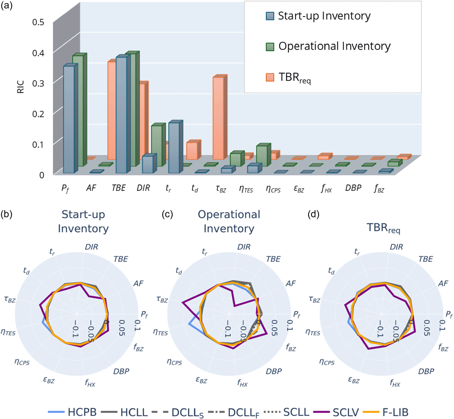
5.3. TFC scenario development
Building upon this parametric study, the next step was to delve deeper into specific TFC architectures to better understand scenarios for Infinity Two and attempt to understand viable R&D pathways for reducing overall tritium inventories and breeding requirements. This included the development of a more bespoke TFC model as well as examination of various operating points for Infinity Two. From the TFC model perspective, cross-referencing more contemporary literature such as the EU DEMO fuel cycle preconceptual design activities (Day et al. Reference Day2022), it becomes apparent that the architectures proposed by Abdou et al. (Reference Abdou, Riva, Ying, Day, Loarte, Baylor, Humrickhouse, Fuerst and Cho2021) and Meschini et al. (Reference Meschini, Ferry, Delaporte-Mathurin and Whyte2023) can be improved upon. As examples, the prior formulations did not explicitly capture the dynamics of both the DIR and fueling system, so those inventories are lost from consideration even though they are expected to be non-trivial given the required fueling throughput of the plasma (Schwenzer et al. Reference Schwenzer, Day, Giegerich and Santucci2022). In addition, the models assumed that tritium not sent to the DIR system is instead sent to the isotope separation system for full separation, which is both non-ideal and unnecessary for a steady-state MFE system where the IFC DT mixture simply needs to be rebalanced and kept below a certain protium content (typically of the order of 1 %) prior to reinjection.
In order to provide a more realistic estimate of TFC parameters in Infinity Two, a new three-loop fuel cycle model shown in Appendix A, figure 18 was generated consistent with the proposed architecture of Day et al. (Reference Day2022) from the EU DEMO pre-conceptual design which utilized the HCPB blanket concept. This model focuses on: (i) maximizing DIR fraction with an aggressive 80 % baseline, (ii) the addition of an intermediate loop with an isotope rebalancing and protium removal system and (iii) accurate accounting for all component inventories. The main driver for these changes is the desire to avoid isotopically separating large amounts of tritium, which for existing technologies such as cryogenic distillation, can lead to large inventory issues associated with the liquid hold-ups, negatively affecting safety and operating costs. For a more detailed explanation of this general architecture, including a rigorous technological assessment and technology choices for each component, readers are directed to Day et al. (Reference Day2022). Not all of the relevant parameters for the model are presented in the literature, including residence time and flow fractions for the various components and subsystems, so a new RTM model had to be constructed from the ground up. The initial model was created using a combination of assumptions from the prior RTM models and flow fractions derived from flow rates and partial pressures presented in Day et al. (Reference Day2022). Once an initial model was established, the residence time in the various components was quantified using the steady-state tritium inventories computed by Schwenzer et al. (Reference Schwenzer, Day, Giegerich and Santucci2022) and the approach of Meschini et al. (Reference Meschini, Ferry, Delaporte-Mathurin and Whyte2023). For this approach, TFC simulations were run in a systematic fashion using the EU DEMO parameters with an HCPB blanket ( $P_{f}$
= 2 GW,
$P_{f}$
= 2 GW, $\tau _{\mathrm{BZ}}$
= 24 h,
$\tau _{\mathrm{BZ}}$
= 24 h, $\eta _{\mathrm{TES}}$
= 0.8, TBE = 0.6 %) and the component residence times were varied one at a time until the relevant component tritium inventories converged to within half a gram of the values listed in Schwenzer et al. (Reference Schwenzer, Day, Giegerich and Santucci2022).
$\eta _{\mathrm{TES}}$
= 0.8, TBE = 0.6 %) and the component residence times were varied one at a time until the relevant component tritium inventories converged to within half a gram of the values listed in Schwenzer et al. (Reference Schwenzer, Day, Giegerich and Santucci2022).
TFC four-corners analysis.
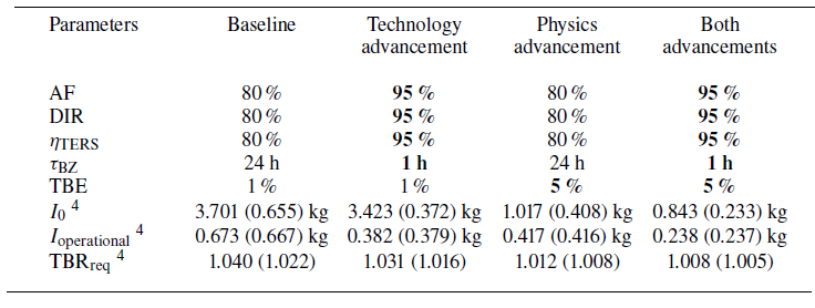
1 The first value in each cell is the nominal parameter value obtained with $t_{r}$
= 24 h. The second value in in each cell is the tritium-lean parameter obtained with
$t_{r}$
= 24 h. The second value in in each cell is the tritium-lean parameter obtained with $t_{r}$
= 0.
$t_{r}$
= 0.
Once the parameters were set, this model was scaled to the Infinity Two configuration with $P_{f}$
= 800 MW and used to model a number of commercial power plant scenarios. The baseline scenario assumed conservative technology values based on the HCPB EU DEMO (DIR = 0.8,
$P_{f}$
= 800 MW and used to model a number of commercial power plant scenarios. The baseline scenario assumed conservative technology values based on the HCPB EU DEMO (DIR = 0.8, $\tau _{\mathrm{BZ}}$
= 24 h,
$\tau _{\mathrm{BZ}}$
= 24 h, $\eta _{\mathrm{TES}}$
= 0.8) but with a commercially relevant AF = 80 %. A relatively conservative physics assumption of TBE = 1 % was also used in this baseline, and a standard value of
$\eta _{\mathrm{TES}}$
= 0.8) but with a commercially relevant AF = 80 %. A relatively conservative physics assumption of TBE = 1 % was also used in this baseline, and a standard value of $t_{d}$
= 5 years was used across all scenarios. A four corners approach employed by the ARIES system study program in Kessel et al. (Reference Kessel2015) and Meschini et al. (Reference Meschini, Ferry, Delaporte-Mathurin and Whyte2023) was then used to examine a variety of advanced and conservative scenarios to better illustrate how the relevant TFC parameters can vary with different R&D emphasis moving forward. The results of this analysis can be seen in table 9. Here, technology advancement assumes DIR = 0.95,
$t_{d}$
= 5 years was used across all scenarios. A four corners approach employed by the ARIES system study program in Kessel et al. (Reference Kessel2015) and Meschini et al. (Reference Meschini, Ferry, Delaporte-Mathurin and Whyte2023) was then used to examine a variety of advanced and conservative scenarios to better illustrate how the relevant TFC parameters can vary with different R&D emphasis moving forward. The results of this analysis can be seen in table 9. Here, technology advancement assumes DIR = 0.95, $\tau _{\mathrm{BZ}}$
= 1 h,
$\tau _{\mathrm{BZ}}$
= 1 h, $\eta _{\mathrm{TES}}$
= 0.95 and AF = 95 %, and the physics advancement assumes TBE = 5 %. The initial value in each box represents the TFC parameters using a standard assumption of reserve inventory (
$\eta _{\mathrm{TES}}$
= 0.95 and AF = 95 %, and the physics advancement assumes TBE = 5 %. The initial value in each box represents the TFC parameters using a standard assumption of reserve inventory ( $t_{r}$
= 24 h with a failure fraction of 25 %), and the second value represents these parameters under a tritium-lean scenario where there is no reserve inventory.
$t_{r}$
= 24 h with a failure fraction of 25 %), and the second value represents these parameters under a tritium-lean scenario where there is no reserve inventory.
As can be seen from this table, using modern architecture and technology/physics assumptions, the operational tritium inventory of a $P_{f}$
= 800 MW power plant can be driven well below one kilogram (675 g as a baseline), and even go as low as half or quarter of a kilogram (238 g in the most optimistic scenario) with additional improvements in both processing and plasma performance. The start-up inventory in this parameter space is primarily driven by reserve inventory requirements, which scale with
$P_{f}$
= 800 MW power plant can be driven well below one kilogram (675 g as a baseline), and even go as low as half or quarter of a kilogram (238 g in the most optimistic scenario) with additional improvements in both processing and plasma performance. The start-up inventory in this parameter space is primarily driven by reserve inventory requirements, which scale with $P_{f}$
and as the inverse of TBE. This reserve inventory requirement can push start-up inventory values to a factor of 5–10 higher than would otherwise be necessary from a purely operational standpoint. A key finding of this analysis shows that the requirement for a significant reserve inventory should be revisited for power plants operating in this physics and technology space, to avoid significant and likely unnecessary inventories of tritium being sequestered away in storage to decay. This will likely require a focus on other approaches to ensuring a robust TFC. Finally, it should be noted that
$P_{f}$
and as the inverse of TBE. This reserve inventory requirement can push start-up inventory values to a factor of 5–10 higher than would otherwise be necessary from a purely operational standpoint. A key finding of this analysis shows that the requirement for a significant reserve inventory should be revisited for power plants operating in this physics and technology space, to avoid significant and likely unnecessary inventories of tritium being sequestered away in storage to decay. This will likely require a focus on other approaches to ensuring a robust TFC. Finally, it should be noted that $\mathrm{TBR}_{\mathrm{req}}$
for such a facility is relatively low (less than 1.05), even for a 5-year doubling time, giving confidence that tritium self-sufficiency is in fact achievable from a breeding perspective and that the roll out of a large fusion ecosystem may not be as constrained as previously postulated (Abdou et al. Reference Abdou, Riva, Ying, Day, Loarte, Baylor, Humrickhouse, Fuerst and Cho2021).
$\mathrm{TBR}_{\mathrm{req}}$
for such a facility is relatively low (less than 1.05), even for a 5-year doubling time, giving confidence that tritium self-sufficiency is in fact achievable from a breeding perspective and that the roll out of a large fusion ecosystem may not be as constrained as previously postulated (Abdou et al. Reference Abdou, Riva, Ying, Day, Loarte, Baylor, Humrickhouse, Fuerst and Cho2021).
Finally, a number of scenarios specific to the Infinity Two start-up phase were evaluated. In these scenarios, it was assumed that a phased approach to DT operation will be employed such that the plasma-on time progressively increases towards a commercially relevant duration of 18–24 months with an AF of at least 80 %. This staged approach helps to improve operational confidence and progressively bootstraps plasma and neutron fluence levels up to commercially relevant levels for critical components, thus allowing for simultaneous development during the operation of the facility (Kessel et al. Reference Kessel2018). For this analysis, a number of scenarios were run using the baseline technology and physics assumptions of the four corners analysis and AF spanning 33 % to 80 %. The plasma-on times of the various phases were set such that there were six months of downtime between operation to allow for inspection and maintenance. It was also assumed that no reserve inventory would be held given both the relatively large inventory requirements discussed previously but also the anticipated lack of knowledge on both mean time between failures and mean time to recovery of the system. Finally, instead of a set doubling time, breeding requirements were derived such that the inventory maintained an adequate level during the plasma off-time and the facility could restart operations again without the need to purchase additional tritium. The results of this analysis indicate that even in the case of low availability (33 %), the $\mathrm{TBR}_{\mathrm{req}}$
is very modest (approximately 1.023) for the Infinity Two start-up phase. This is also consistent with what is expected in that of a higher availability commercial system, assuming an overall similar TFC architecture and design space is used.
$\mathrm{TBR}_{\mathrm{req}}$
is very modest (approximately 1.023) for the Infinity Two start-up phase. This is also consistent with what is expected in that of a higher availability commercial system, assuming an overall similar TFC architecture and design space is used.
6. Discussion
In addition to the high-level quantitative analyses described in §§ 3, 4 and 5, a qualitative evaluation was performed to gauge the potential of each of the reference concepts against the FusionDirect objectives in categories which could not be quantitatively evaluated under the given timescales and resources. This qualitative analysis reviews and builds upon the significant body of work focused on comprehensive blanket evaluations including the Blanket Comparison and Selection Study (Smith et al. Reference Smith, Baker, Sze, Morgan, Abdou, Piet, Schultz, Moir and Gordon1985), various ARIES activities (El-Guebaly et al. Reference El-Guebaly, Raffray, Malang, Lyon and Ku2005; Kessel et al. Reference Kessel2015), the EU DEMO Blanket Program (Hernández et al. 2023; Federici et al. Reference Federici2014; Stork et al. Reference Stork2014) and other miscellaneous surveys (Raffray et al. Reference Raffray, Akiba, Chuyanov, Giancarli and Malang2002; Meier Reference Meier2014). The primary and most important finding of this qualitative evaluation is that in isolation an overall top-rated blanket concept is not readily apparent at such an early stage of development. In general, each concept has both advantages and disadvantages when compared directly against alternatives, and the outcome of any evaluation is highly dependent on assumptions and design objectives for the device in question. In addition, each blanket concept must be paired with a specific confinement concept to determine suitability for an integrated, economically viable energy producing system. In this regard, there are relatively few stellarator design studies to date, many of which were not wholly self-consistent (Najmabadi et al. Reference Najmabadi2008; Warmer et al. Reference Warmer, Beidler, Dinklage and Wolf2016). This emphasizes the need for more thorough and comprehensive design activities moving forward.
A second and broadly applicable finding is that the selection and development of appropriate materials, particularly structural materials, is a driving consideration for both the performance and deployability of all fusion blanket concepts. Numerous factors must be considered in the selection of appropriate materials, including material availability and cost, fabricability, joining techniques, mechanical and thermophysical properties, radiation effects, chemical compatibility and corrosion issues, safety and waste disposal aspects and nuclear properties. For designers, a particularly important consideration when selecting materials is the expected operating conditions, including mechanical, thermal and radiation loading environments during the lifetime of the component. It should be stressed that the detailed minimum and maximum operating temperature limits for a given structural material are strongly dependent on the specific system design and manner in which these materials will be employed (Zinkle & Ghoniem Reference Zinkle and Ghoniem2000; Zinkle & Snead Reference Zinkle and Snead2014), but will also dictate overall thermal performance as shown in § 4. In this regard, a blanket concept cannot be truly understood without also having a rigorous understanding of materials performance in the prescribed environment, including degradation of that performance over its operating life. A recent effort by the US fusion materials community and the Electric Power Research Institute attempted to capture these materials considerations, including a technology readiness assessment and technology road map for leading material systems, and readers are directed there for further details (U.S. Fusion Materials Coordinating Committee 2024).
Finally, it should be noted that while Infinity Two needs to demonstrate commercial relevance, it is not itself a commercial system. Given the relative maturity of blanket technology and the aggressive developmental timelines, it is unlikely that a concept will be deployed under the FusionDirect program which is fully optimized prior to a first-of-a-kind commercial plant. In this regard, emphasis is placed on identifying a baseline blanket which can be rapidly deployed for Infinity Two while also maintaining flexibility and opportunities for higher performing concepts later in development. What follows is a discussion of key findings for the six blanket concepts considered in this study, a graphical summary of which can be found in figure 9.
High-level comparison of the status and developmental pathways for various fusion blanket concepts. Green arrows indicate R&D opportunities for advancing performance of proposed concepts while red arrows indicated required R&D prior to the implementation of proposed concepts.
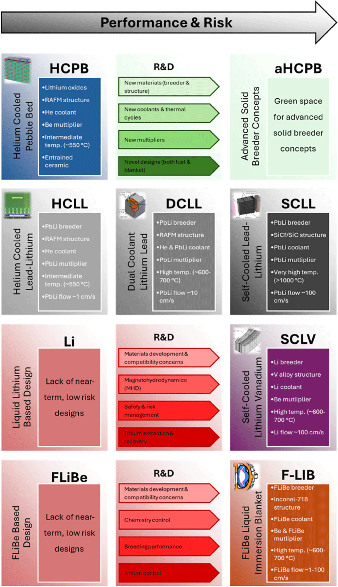
6.1. Solid breeders: the promising solution
Solid breeders, specifically ceramic-based solid concepts, are currently considered to be the baseline approach internationally. The primary motivation for the development of solid breeder blankets stems from the desire to overcome the limitations of liquid breeders, including a focus on higher chemical inertness, elimination of MHD effects and mitigation of corrosion concerns (Johnson et al. Reference Johnson, Kummerer and Roth1988). In addition, solid breeders also tend to have higher lithium densities than liquids, which, in combination with inherent moderating elements such as oxygen, make them advantageous for designing more compact blankets from both a breeding and shielding perspective. For these reasons, solid blankets have been seen as a favored approach since the 1980s, with extensive international R&D programs aimed at confirming the suitability of solid breeders designs from both a materials science and engineering perspective (van der Laan et al. Reference van der Laan, Kawamura, Roux and Yamaki2000). They are also the most heavily invested-in blanket concept from the international public programs. To illustrate this point, it should be noted that four of the six Test Blanket Modules planned as part of the ITER program will utilize solid blanket designs (Giancarli et al. Reference Giancarli2020). Recent preconceptual design studies in support of the EU DEMO program have shown that existing solid breeders are high-performing and robust blanket candidates while also enjoying a relatively mature technology basis, thanks in large part to their usage of leading RAFM steels as the structural material (Zhou et al. Reference Zhou, Hernández, Pereslavtsev, Kiss, Retheesh, Maqueda and Park2023a ). They also have strong and reliable performance when compared against the other concepts, as verified in all three analyses presented previously as well as preconceptual design studies under the EU DEMO program (Zhou et al. Reference Zhou, Hernández, Pereslavtsev, Kiss, Retheesh, Maqueda and Park2023a ). In particular, the neutronics performance appears to pair well with T1E stellarator designs. Finally, their performance in off-normal events is also anticipated to be more predictable due to the solid fuel form and usage of inert He coolant, which is seen as advantageous for early fusion nuclear systems (Jin & Yin Reference Jin and Yin2017).
Although a significant R&D effort on ceramic breeder development has laid a strong foundation over the past several decades, there are still challenges which must be addressed. First is the traditional reliance on beryllium multipliers in order to achieve adequate TBR, which represents a potential safety, supply chain and cost issue (Scaffidi-Argentina et al. Reference Scaffidi-Argentina, Longhurst, Shestakov and Kawamura2000; Longhurst et al. Reference Longhurst2011; Kolbasov et al. Reference Kolbasov, Khripunov and Biryukov2016; Shimwell et al. Reference Shimwell, Lilley, Morgan, Packer, Kovari, Zheng and McMillan2016). The second challenge is related to the thermal and mechanical behavior of solid breeder materials under the complex nuclear fusion loading conditions, particularly at long time scales, which can lead to significantly degraded materials properties, induce volumetric change, lead to breeder performance drops and potentially affect chemical behavior leading to increased interaction with structures and/or induce lithium transport within the blanket (van der Laan et al. Reference van der Laan, Reimann and Fedorov2016). Combined with the need for existing designs to shut down in order to refuel, this can have implications on the overall commercial system viability. The third challenge relates to tritium extraction from the ceramic materials in vessel, which comprises complex, multi-physics interactions due to a variety of factors including steep temperature gradients, radiation-induced defects that can act as traps and complex chemistry of the system due to lithium burn-up and/or residual impurities in the sweep gas. Understanding and appropriately accounting for this tritium release is critical both from a safety and fuel cycle viability perspective (van der Laan et al. Reference van der Laan, Reimann and Fedorov2016; Cristescu & Draghia Reference Cristescu and Draghia2020; Simon et al. Reference Simon, Humrickhouse and Lindsay2022). Lastly, the relatively large volume of ceramic breeder and multiplier required for breeding blankets in future power systems and the need for regular refueling in order to maintain breeding performance will necessitate safe and economical solutions for reprocessing and recycling, thus minimizing cost and waste (Leys et al. Reference Leys, Leys and Knitter2021). However, several R&D avenues have been identified to address these shortcomings, including using new materials (Zinkle et al. Reference Zinkle, Boutard, Hoelzer, Kimura, Lindau, Odette, Rieth, Tan and Tanigawa2017; Hernández & Pereslavtsev Reference Hernández and Pereslavtsev2018; Davies & Murphy Reference Davies and Murphy2021; Samolyuk & Edmondson Reference Samolyuk and Edmondson2021; Bhattacharya et al. Reference Bhattacharya, Zinkle, Henry, Levine, Edmondson, Gilbert, Tanigawa and Kessel2022; Bhardwaj et al. Reference Bhardwaj, Cheng, Sprouster, Cunningham, Rani, Trelewicz and Snead2024), coolants (Syblik et al. Reference Syblik, Vesely, Entler, Stepanek and Dostal2019; Wang et al. Reference Wang, Hernández, Chen and Zhou2019; Wu et al. Reference Wu, Ma, Gao, Liu, Shan, Huang, Wang, Zhang and Ran2020), multipliers (Hernández & Pereslavtsev Reference Hernández and Pereslavtsev2018; Zhou et al. Reference Zhou, Hernández, Kang and Pereslavtsev2019; Gaisin et al. Reference Gaisin2020) and designs/design methodology (Shimwell et al. Reference Shimwell, Lilley, Morgan, Packer, Kovari, Zheng and McMillan2016; Sharafat et al. Reference Sharafat, Williams, Ghoniem, Ghoniem, Shimada and Ying2016; Badalassi Reference Badalassi2024) to better meet the needs of stellarators.
6.2. PbLi-based breeders: a compelling alternative
PbLi-based designs are the second most mature family of concepts, with the slow flowing concepts having near equal footing with solid breeders in terms of technical maturity, due in large part to the reduced MHD related issues compared with fast flowing concepts (Hernández et al. 2023). In addition, these designs mitigate most, if not all, of the primary risks associated with ceramic breeders, including reliance on Be, mitigation of radiation and thermal stability issues, online tritium extraction/refueling and potential dual usage as a coolant for design simplification. As shown in the analysis above, PbLi designs have performance which could be an appropriate if not optimal match for T1E blanket requirements should the issues with solid breeders prove insurmountable. In addition, PbLi-based concepts have a well-established developmental pathway which is relevant for both near-term systems such as Infinity Two as well as longer-term, higher-performance commercial systems. This is due to the staged implementation pathway for the HCLL to DCLL to SCLL, which can be implemented over time as higher performing materials become available and operational basis improves (Smolentsev et al. Reference Smolentsev, Morley, Abdou and Malang2015; Tillack et al. Reference Tillack, Bringuier, Holmes, Holland, Santos-Novais and Maldonado2022). Currently the PbLi-based family of blankets is the only one which has such a well-defined developmental pathway. In addition, the HCLL and DCLL designs share many similar R&D pathways with the solid blanket concepts as they are all currently proposing Fe-based materials as the primary structure, which is beneficial from a leveraging and risk mitigation standpoint. For these reasons, the DCLL has been the favored design in the US fusion program over the past several decades (Abdou et al. Reference Abdou, Morley, Smolentsev, Ying, Malang, Rowcliffe and Ulrickson2015; Kessel et al. Reference Kessel2018) and is seen as a potential risk-mitigating fallback design for FusionDirect .
However, PbLi also has its own share of challenges. Similar to pure lithium, PbLi suffers from being chemically reactive with water and air, although to a lesser extent (Malang & Mattas Reference Malang and Mattas1995), it has potentially severe compatibility issues with structural materials (Romedenne et al. Reference Romedenne, Zhang, Su and Pint2023) and finally tritium extraction is not a fully solved problem, although there is a stronger technology basis than for pure lithium (Garcinuño et al. Reference Garcinuño, Rapisarda, Antunes, Utili, Fernández-Berceruelo, Sanz and Ibarra2018; Humrickhouse & Merrill Reference Humrickhouse and Merrill2018). An additional issue specific to the DCLL and SCLL concepts which propose to utilize the PbLi as a coolant is that of MHD effects which result from a conducting material being flown in a high background magnetic field environment. This can increase pumping power requirement (due to MHD pressure drop), inhibit heat transfer (via suppression of turbulent flow) and complicate tritium and corrosion product transport (Smolentsev Reference Smolentsev2021) and in general is not a well-understood phenomenon at fusion relevant conditions. Next, as a breeder the performance of PbLi is not as high as that of either the solids breeders or pure lithium, and PbLi concepts typically require $^{6}$
Li enrichment greater than 90 wt % in order to achieve similar breeding levels, as shown in the neutronics analysis and the literature (van der Laan et al. Reference van der Laan, Reimann and Fedorov2016). Finally, lead-lithium alloys have some specific design challenges such as the high density resulting in the requirement for stronger structures to limit mechanical stresses and potential challenges associated with liquid metal spills which could be challenging to clean (Hernández & Pereslavtsev Reference Hernández and Pereslavtsev2018; Piet et al. Reference Piet, Jeppson, Muhlestein, Kazimi and Corradini1987).
$^{6}$
Li enrichment greater than 90 wt % in order to achieve similar breeding levels, as shown in the neutronics analysis and the literature (van der Laan et al. Reference van der Laan, Reimann and Fedorov2016). Finally, lead-lithium alloys have some specific design challenges such as the high density resulting in the requirement for stronger structures to limit mechanical stresses and potential challenges associated with liquid metal spills which could be challenging to clean (Hernández & Pereslavtsev Reference Hernández and Pereslavtsev2018; Piet et al. Reference Piet, Jeppson, Muhlestein, Kazimi and Corradini1987).
6.3. Pure lithium and FLiBe-based breeders: not the right fit
Both pure lithium and FLiBe-based concepts, while novel and potentially promising, are seen as being the least mature concepts as well as somewhat niche in application space. While they offer similar benefits as the PbLi concepts (no radiation/thermomechanical damage in the breeder material, online tritium extraction/refueling and potential dual usage as a coolant), they both require dedicated developmental pathways which are tangential from solid and PbLi blanket concepts. This is due in large part to requirements for new structural materials, unique technologies associated with tritium extraction and chemistry control, and the general incompatibility with separately cooled or dual-cooled approaches (though this is being revisited in the case of lithium (Lord et al. Reference Lord, Bennett, Harrington, Cooper, Lee-Lane, Cureton, Olde, Thompson, Jayasundara and Meatyard2024)). In this respect they lack readily apparent, nearer-term implementable designs and so present an ‘all or nothing’ investment paradigm that makes them high risk for a venture such as FusionDirect .
It is also important to note that proponents pursuing these concepts are motivated at least in part by confinement concept considerations which differ from that of the T1E high-field stellarator approach. For pure lithium, development is largely being driven by confinement concepts where the in-vessel volume is bifurcated into segments of shield-only builds (due to space constraints) and largely unconstrained builds which must optimize breeding (in order to accommodate the loss of breeding volume in those shield-only volumes). Such is the case for spherical tokamaks where the compact nature and shape means the incorporation of a sizable inboard breeder blanket is not possible, and the outboard breeding must therefore be maximized in order to achieve tritium self-sufficiency (Lord et al. Reference Lord, Bennett, Harrington, Cooper, Lee-Lane, Cureton, Olde, Thompson, Jayasundara and Meatyard2024). As can be seen from the parametric analysis in § 3, this is where lithium blanket concepts excel. The FLiBe-based designs are being driven by the desire to enable extremely compact devices, and so the associated blanket designs must maximize the shielding value of the breeding zone. As can be seen from the parametric analysis in § 3, this is where FLiBe concepts excel, although it does require design modifications elsewhere to ensure that the TBR requirements are met simultaneously. An example of this design trade-off space is the Commonwealth Fusion Systems’ ARC design (Sorbom et al. Reference Sorbom2015), where structure and penetration in the breeding zone are kept to essentially zero in order to achieve the required TBR (Segantin et al. Reference Segantin, Testoni, Hartwig, Whyte and Zucchetti2020). This is not currently applicable to Infinity Two, where it is anticipated that the fueling systems, heating systems and coolant manifolds for the divertor and first wall will have non-trivial space claims in the blanket region, and maintenance approaches may require additional structure for modularization. Neither of the motivating factors for pure lithium or FLiBE are expected to apply to current or future T1E stellarator designs, but it is important to recognize these driving considerations and emphasize the need for performing blanket design early in the design life cycle to ensure the blanket concept integrates with the overall system requirements.
For lithium, additional technical challenges are primarily driven by the high chemical reactivity, which represents significant engineering and safety challenges. From an engineering perspective, the reactivity presents challenges for both structural and functional (i.e. insulators for mitigation of MHD effects) materials compatibility since lithium is reactive with many materials and alloying constituents proposed for fusion applications (Si et al. Reference Si, Lu, Ji, Zhang, Yao, Wang and Chu2020; Muroga et al. Reference Muroga, Tanaka, Kondo, Nagasaka and Xu2009; Smith et al. Reference Smith, Natesan, Park, Reed and Mattas2000). Lithium will also suffer from MHD related issues similar to PbLi, but with higher electrical conductivity, and may prove difficult for the complex and strong magnetic fields of T1E stellarators (Smolentsev Reference Smolentsev2021). Related to both safety and engineering considerations is lithium’s high affinity for tritium and the requirement that tritium concentration in the medium be kept low (approximately 1 appm) in order to maintain the blanket and overall plant tritium inventories to acceptable levels as shown in § 5. The low vapor pressure of tritium above molten lithium makes extraction of tritium difficult and requires the development of new extraction methodologies. Currently proposed extraction methods include the Maroni process (Maroni et al. Reference Maroni, Wolson and Staahl1975), direct electrolysis (Teprovich et al. Reference Teprovich, Mercado, Hector, Olson, Ganesan, Babineau and Garcia-Diaz2019) and distillation columns (Christenson et al. Reference Christenson, Moynihan and Ruzic2018), all of which are relatively immature and need significant improvement to show power plant relevance. An additional safety consideration is that lithium is highly reactive to water, air and other substances, especially at the high temperatures expected in fusion energy systems. The resulting extreme exothermic reactions which could lead to confinement challenges for radiological inventories, such as mobilization of the tritium content in the lithium or release of activation products from the surrounding structures (Reyes et al. Reference Reyes, Anklam, Meier, Campbell, Babineau, Becnel, Taylor and Coons2016).
The main challenge with utilizing FLiBe or other molten salts stems from a lack of compatibility with existing low activation structural materials. This is due to the relatively high melting point, particularly for FLiBe, which can narrow temperature design windows to unacceptably low levels when incorporating upper end structural material limits (Zinkle & Ghoniem Reference Zinkle and Ghoniem2000). Chemical compatibility with structural and functional materials is another concern, particularly under irradiation conditions which can lead to hydrofluoric acid production via radiolysis and requires tight chemistry control in order to avoid unacceptable corrosion (Pint et al. Reference Pint, Evangelia (Lila), Dino and Paul2024). These are key concerns which may require the development of entirely new materials systems and could potentially hamper the deployment of molten salt blanket concepts in the near term. The final challenge is that of tritium solubility in FLiBe is extremely low and could result in elevated tritium loss via diffusion and trapping in blanket structural materials (Wong et al. Reference Wong2005). Ultimately, these challenges, in combination with the difficulty of reaching an adequate TBR as outlined in § 3, make FLiBe or other salt-based blankets unattractive for FusionDirect at this point in time.
7. Conclusion
T1E is pursuing an ambitious and uniquely direct path to an FPP. This requires timely identification, analysis, evaluation and down selection of potential blanket concepts. The focus of this study was to identify a baseline blanket which can be rapidly deployed for the Infinity Two FPP while also maintaining flexibility and opportunities for higher performing concepts later in development. Guiding principles driving the study were identified, consistent with the overarching objectives of the FusionDirect program. A literature survey was conducted to establish reference concepts, of which six were identified: the HCPB, HCLL, DCLL, SCLL, SCLV and the F-LIB. Next, a series of quantitative and qualitative analyses were performed. This included a neutronics analysis for determining tritium breeding and shielding performance, a thermal analysis for determining overall system efficiency and net electric output potential, and a TFC analysis for understanding the impact of blanket choices and system parameters on closure of the fuel cycle. In conjunction with these quantitative activities, a qualitative study was performed to understand other design drivers which could not be captured via analysis.
The results of this comprehensive study indicated that the HCPB is the most promising concept for Infinity Two. This is primarily motivated by the neutronics performance at applicable blanket build depths, where the HCPB was able to achieve a TBR of 1.30 in low engineering fidelity simulations, as well as the relatively mature technology basis. In addition, there appears to be significant opportunity for continued improvement in this family of concepts using new materials, coolant, multipliers and designs. The PbLi family of concepts, particularly the DCLL, offers a compelling alternative to the HCPB. These concepts maintain similar developmental pathways while simultaneously mitigating much of the technical risk, namely reliance on Be, mitigation of radiation and thermal stability issues, online tritium extraction/refueling and potential dual usage as a coolant for design simplification. Both concepts are expected to enable reasonably high thermal efficiencies of greater than 30 % with a Rankine cycle. In addition, both concepts are compatible with a viable fuel cycle, with anticipated operational inventories of less than one kilogram (approximately 675 g) for an 800 MW $_{\mathrm{th}}$
fusion device and a required TBR (TBR
$_{\mathrm{th}}$
fusion device and a required TBR (TBR $_{\mathrm{req}}$
) of less than 1.05.
$_{\mathrm{req}}$
) of less than 1.05.
Acknowledgements
The authors would like to acknowledge the support of the UW-Madison Center for High Throughput Computing (University of Wisconsin–Madison 2024b) for providing computational resources used to perform neutronics calculations.
Editor Per Helander thanks the referees for their advice in evaluating this article.
Funding
This work was supported by Type One Energy Group Inc.
Declaration of interests
The work of M.S.T. was performed as a consultant and was not part of the employee’s responsibilities at the University of California-San Diego.
Appendix A. Additional figures
Radial build diagram of the concentric toroidal shell layers in the helium-cooled pebble bed blanket concept for this high-throughput parametric neutronic study. Material layers are based on those in (Zhou et al. Reference Zhou, Hernández, Pereslavtsev, Kiss, Retheesh, Maqueda and Park2023a , Reference Zhou, Rey, Hernández, Abou-Sena, Lux, Arbeiter, Schlindwein and Schwabb ); material compositions provided in volume percent.
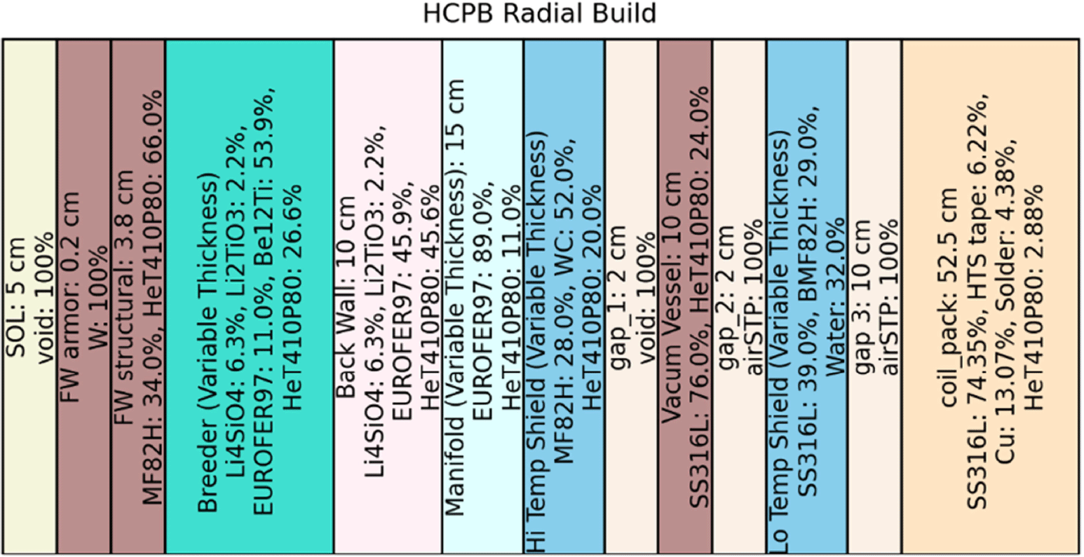
Radial build diagram of the concentric toroidal shell layers in the helium-cooled lead-lithium blanket concept for this high-throughput parametric neutronic study. Material layers are based on those in Aubert et al. (Reference Aubert2018); Jaboulay et al. (Reference Jaboulay, Aiello, Aubert and Boullon2019); Aiello et al. (Reference Aiello, Aubert, Jonquères, Li Puma, Morin and Rampal2014); material compositions provided in volume percent. The manifold layer was kept at a constant multiple of 0.2 times the breeder thickness.
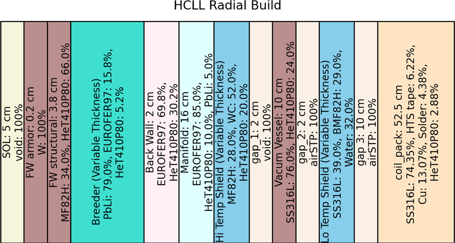
Radial build diagram of the concentric toroidal shell layers in the dual-cooled lead-lithium blanket concept for this high-throughput parametric neutronic study. Material layers are based on those in Davis et al. (Reference Davis, Harb, El-Guebaly, Wilson and Marriott2018); material compositions provided in volume percent.

Radial build diagram of the concentric toroidal shell layers in the self-cooled lead-lithium blanket concept for this high-throughput parametric neutronic study. Material layers are based on those in Kessel et al. (Reference Kessel2015); material compositions provided in volume percent.
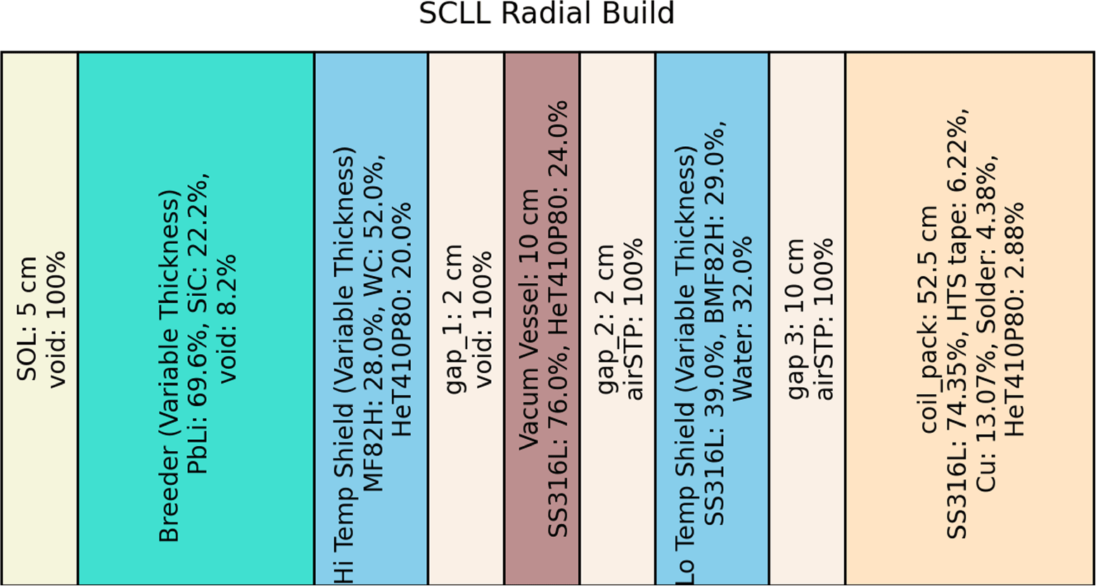
Radial build diagram of the concentric toroidal shell layers in the self-cooled lithium (breeder) vanadium (structure) blanket concept for this high-throughput parametric neutronic study. Material layers are based on those in Kessel et al. (Reference Kessel2015); material compositions provided in volume percent.
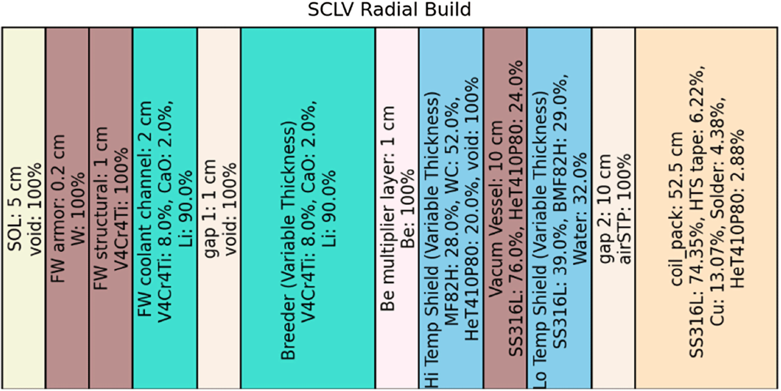
Radial build diagram of the concentric toroidal shell layers in the FLiBe liquid immersion blanket concept for this high-throughput parametric neutronic study. Material layers are based on those in Segantin et al. (Reference Segantin, Testoni, Hartwig, Whyte and Zucchetti2020, Reference Segantin, Meschini, Testoni and Zucchetti2022); Bae et al. (Reference Bae, Peterson and Shimwell2022); material compositions provided in volume percent.

Parametric TFC layouts of (a) separately cooled blanket concepts, (b) dual-cooled concepts and (c) self-cooled concepts.
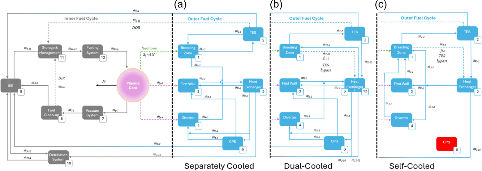
(a) The T-S diagram of Rankine cycle. (b) Scheme of Rankine cycle with reheat.

Three-loop architecture based the EU DEMO preconceptual design.
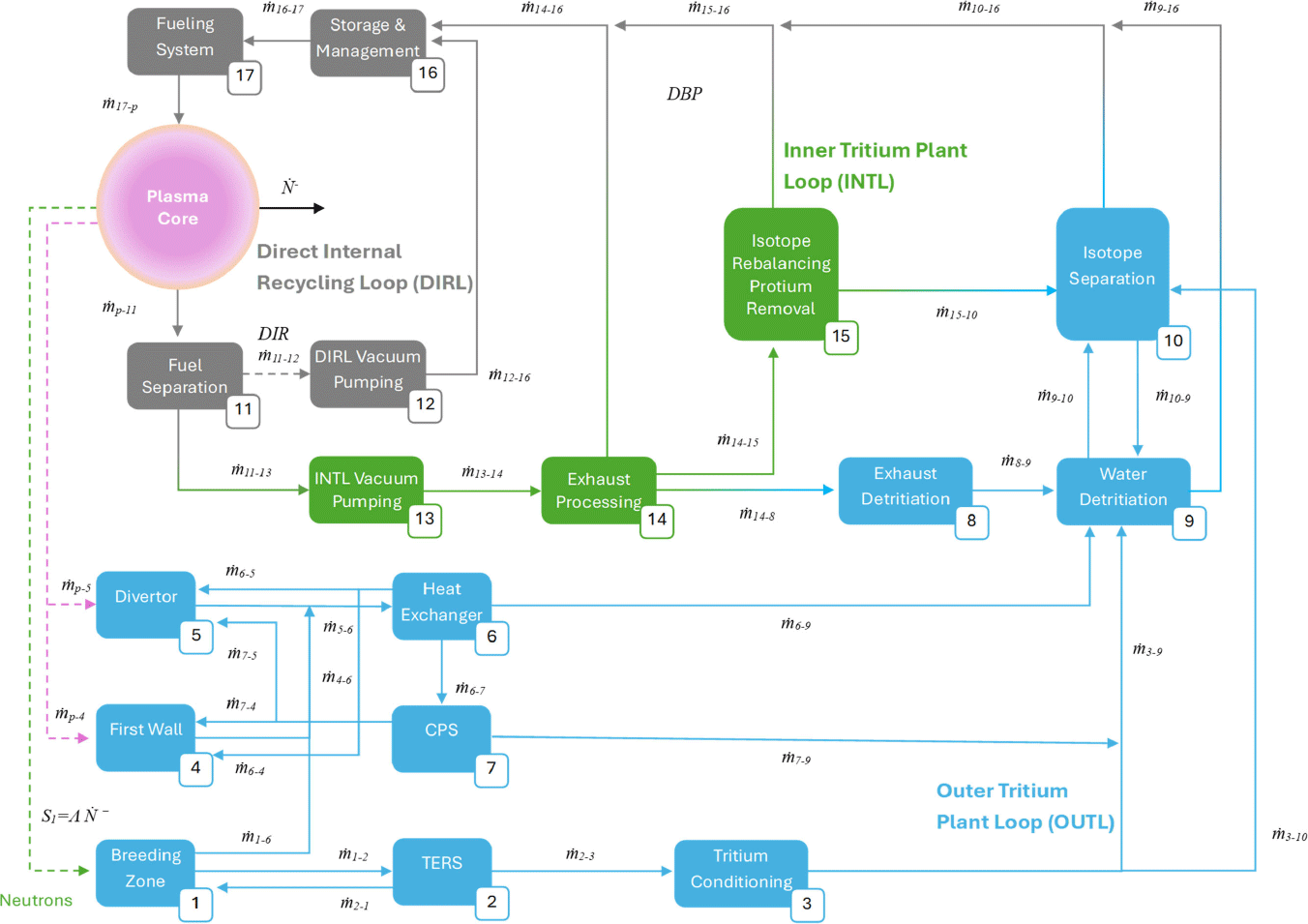


 Open access