


1 Introduction
Recent advances in inertial confinement fusion (ICF) with demonstration of ignition[ Reference Zylstra, Hurricane, Callahan, Kritcher, Ralph, Robey, Ross, Young, Baker, Casey, Döppner, Divol, Hohenberger, Le Pape, Pak, Patel, Tommasini, Ali, Amendt, Atherton, Bachmann, Bailey, Benedetti, Hopkins, Betti, Bhandarkar, Biener, Bionta, Birge, Bond, Bradley, Braun, Briggs, Bruhn, Celliers, Chang, Chapman, Chen, Choate, Christopherson, Clark, Crippen, Dewald, Dittrich, Edwards, Farmer, Field, Fittinghoff, Frenje, Gaffney, Johnson, Glenzer, Grim, Haan, Hahn, Hall, Hammel, Harte, Hartouni, Heebner, Hernandez, Herrmann, Herrmann, Hinkel, Ho, Holder, Hsing, Huang, Humbird, Izumi, Jarrott, Jeet, Jones, Kerbel, Kerr, Khan, Kilkenny, Kim, Geppert, Kleinrath, Kleinrath, Kong, Koning, Kroll, Kruse, Kustowski, Landen, Langer, Larson, Lemos, Lindl, Ma, MacDonald, MacGowan, Mackinnon, MacLaren, MacPhee, Marinak, Mariscal, Marley, Masse, Meaney, Meezan, Michel, Millot, Milovich, Moody, Moore, Morton, Murphy, Newman, Di Nicola, Nikroo, Nora, Patel, Pelz, Peterson, Ping, Pollock, Ratledge, Rice, Rinderknecht, Rosen, Rubery, Salmonson, Sater, Schiaffino, Schlossberg, Schneider, Schroeder, Scott, Sepke, Sequoia, Sherlock, Shin, Smalyuk, Spears, Springer, Stadermann, Stoupin, Strozzi, Suter, Thomas, Town, Tubman, Trosseille, Volegov, Weber, Widmann, Wild, Wilde, Van Wonterghem, Woods, Woodworth, Yamaguchi, Yang and Zimmerman 1 ], along with the emerging field of high-repetition-rate high-energy-density (HED) science[ Reference Remington, Rudd and Wark 2 ], will require the development of laser amplifiers with increasing energies as well as high repetition rates to transform the proof-of-principle results (ignition) to real-world applications (inertial fusion energy (IFE), IFE power plants). In addition, to develop lasers for fast ignition and direct-drive ICF[ Reference Tabak, Norreys, Tikhonchuk and Tanaka 3 ] or to achieve ultrashort pulse duration for high-intensity laser–plasma interactions, the amplifier must also support wide-bandwidth amplification. The requirement for high energy coupled with a high repetition rate increases the heat load, and therefore the temperature rise within the gain medium in the power amplifier section of the laser. The substantial thermal load experienced by laser materials in such high average power laser systems leads to detrimental effects, including wavefront aberrations and stress-induced birefringence. For the latter, the material behaves as a nonuniform polarization retardation element, where the effect on the polarization state of the incoming light varies across the aperture of the beam. This causes beam depolarization, that is, a degradation of the polarization uniformity of a beam propagating through the amplifier head. Low polarization uniformity of the output beam reduces the efficiency of polarization-sensitive processes (e.g., frequency conversion in nonlinear crystals and pulse compression using diffraction gratings) and degrades the beam quality. The next generation of high-energy and high-repetition-rate laser amplifiers will require compensation of the thermally induced depolarization not just for the central wavelength, but also for the full bandwidth of the amplified spectrum. This paper reports on the design of such an amplifier based on multi-slab, two-head architecture. We also present numerical simulations showing the advantages of the new design compared to designs traditionally used for thermally induced depolarization compensation in laser amplifiers.
Schematic diagram of the modeled cavity. EM, end mirror; QR, 90° polarization rotating quartz rotator; P1 and P2: passes 1 and 2.

2 Modeling methodology
A laser amplifier typically consists of a gain medium (or multiple gain media) with appropriate cooling (gas, liquid or conductor) and a cavity to propagate the seed beam multiple times through the gain medium. An effective way to improve the cooling of the gain medium is to increase the number of surfaces by splitting a bulk gain medium into multiple slabs and flowing coolant between the slabs. One such architecture was proposed by Bayramian et al. [Reference Bayramian, Armstrong, Ault, Beach, Bibeau, Caird, Campbell, Chai, Dawson, Ebbers, Erlandson, Fei, Freitas, Kent, Liao, Ladran, Menapace, Molander, Payne, Peterson, Randles, Schaffers, Sutton, Tassano, Telford and Utterback 4 ] at the Lawrence Livermore National Laboratory (LLNL) in the Mercury project, where a gas-cooled multi-slab amplifier at room temperature was first demonstrated utilizing ytterbium-doped strontium fluorapatite (Yb:S-FAP) as the gain medium. Energy in excess of 50 J at 10 Hz was extracted using one amplifier head. Cryogenic gas cooling was introduced by Rutherford Appleton Laboratory for an ytterbium-doped yttrium aluminum garnet (Yb:YAG) gain medium and an energy of 150 J at 10 Hz was demonstrated at a temperature of 145 K[ Reference Divoký, Pilař, Hanuš, Navrátil, Denk, Severová, Mason, Butcher, Banerjee, De Vido, Edwards, Collier, Smrž and Mocek 5 ]. The thermally induced depolarization losses for the cryogenic gas-cooled Yb:YAG amplifier was reported as 9%[ Reference Slezák, Sawicka-Chyla, Divoký, Pilar, Smrz and Mocek 6 ], which was further optimized to 3%[ Reference Smrz, Divoky, Pilar, Slezak, Vojna, Hanus, Navratil, Denk, Severová, Paliesek, Mason, Phillips, Clarke, Butcher, Banerjee, De Vido and Mocek 7 ] at 146 J, 10 Hz operation for second and third harmonic generation.
Traditionally, thermally induced depolarization compensation within a laser cavity is achieved via the introduction of a quartz rotator (QR) between two amplifier heads to rotate the polarization state of the beam emerging out of the first amplifier head by 90° before injecting it into the second head[ Reference Koechner and Rice 8 ]. This approach assumes identical heat loads and temperature profiles, and thus the same induced stresses in both the amplifier heads, along with zero multiplexing angles inside the laser cavity. However, the above conditions are not achievable in experiments due to the multiplexing angle of the multi-pass amplifier cavity, pump nonuniformity and cooling conditions of the heads, as well as the nonuniform extraction of the amplifier heads. Furthermore, the polarization rotation of the QR is wavelength-dependent, and the QR is designed and cut to a thickness that will rotate the polarization of only the central wavelength of the seed spectrum by 90°. Wavelengths at the extremes of the seed spectrum experience non-optimal polarization rotation, thus reducing the thermally induced depolarization compensation effectiveness. Mason and De Vido[ Reference Mason and De Vido 9 ] described a laser amplifier module for a multi-slab amplifier architecture where the polarization optics (i.e., a QR) are placed at the center of the amplifier head with an equal number of laser gain material slabs placed on each side. Although this laser amplifier design compensates the thermally induced depolarization of the groups of slabs before and after the QR, it does not address multiplexing angle and broad-bandwidth effects on depolarization.
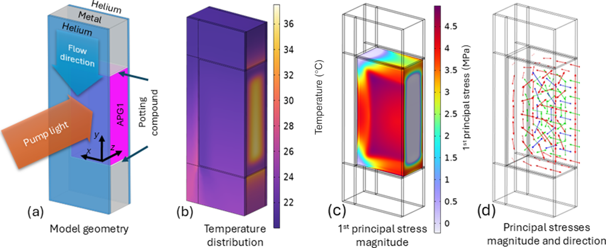
Finite-element method analysis: (a) model geometry, (b) temperature distribution, (c) distribution of the first principal stress magnitude, and (d) principal stresses magnitude and direction with first principal stress in red, second principal stress in green and third principal stress in blue. Only half of the laser slab is simulated due to symmetry.
In this paper, a two-head image-relayed angular and polarization multiplexed amplifier cavity is modeled and analyzed. The seed beam propagates through both the amplifier heads for two passes using an image-relayed far-field angular multiplexing scheme and the polarization of the beam is rotated by 90° to separate the first two passes from the subsequent two additional passes, totaling a four-pass cavity. As the polarization state of the beam is reset after pass 2 (when the beam propagates through a polarizer), to estimate the thermally induced depolarization losses, the cavity was modeled (for simplification) as a two-pass, two-head angularly multiplexed cavity only. Figure 1 shows a schematic diagram of the modeled cavity, using a 4f-image relay telescope.
Theoretical simulations were performed to estimate the depolarization losses within this cavity for a Nd:APG-1 based diode pumped multi-slab amplifier operating at 10 Hz. The central wavelength of amplification was chosen as 1060 nm with a 30 nm bandwidth, while the multiplexing angle and the pump beam size were chosen to be 15 mrad (0.86°) and 80 mm × 80 mm, respectively. The two amplifier heads were end-pumped from both the sides (pumping not shown in Figure 1) by 880 nm diodes. A Frantz–Nodvik-based laser energetics model was used to compute spatially-resolved, time-averaged heat loads in every slab. The spatial shape of the pump was a weighted average pump profile at the center of each slab (computed from Zemax OpticStudio simulation of the pump delivery system). Further, absorption within slabs as a function of time was computed by pumping in a series of temporal steps and allowing the excited state populations to evolve between steps. The model assumes a peak pump power of 2.6 MW for each amplifier head. The spatial shape of the seed beam was approximated as a 20th-order super-Gaussian. After extraction, the remaining excited state populations were allowed to decay to the end of the shot cycle. All decay models incorporated fluorescence branching ratios and non-radiative decay. Finally, the heat loads were time-averaged over the period determined as the reciprocal of the laser system repetition rate. The computed volumetric heat loads were then passed to a finite-element model in COMSOL Multiphysics. The model assumed a fixed gas flow (100 m/s) of room temperature helium gas coolant and a reference pressure of 8 bar. A ‘k-ε’ turbulent flow model was used in the numerical simulation to approximate the turbulent kinetic energy and its dissipation. The steady-state temperature distribution was calculated using a conjugate heat transfer solver, which integrates the non-isothermal flow model to couple the conductive and convective heat transfer in the gas, with conductive heat transfer in the solids. Finally, thermal stresses in the laser slab were computed using a thermal expansion coupling. In this calculation, we simulated only the thermal expansion of the laser slab, which is held by a compliant potting compound within a rigid frame. As the stresses generated in the cladding are de-coupled from the gain medium, due to the elasticity of the potting compound, the cladding stresses and thermal management are outside the scope of this paper. Finally, the spatially varying stress tensor was exported to MATLAB, where the stress-optics law[ Reference Dally, Riley and Kobayashi 10 ] was used to calculate the three orthogonal components of the refractive index.
Figure 2 shows the model geometry, temperature distribution, first principal stress magnitude and the three-principal stress magnitude and direction for a representative gain slab. Within each mesh element of the finite-element model, the two eigenpolarization states were calculated assuming the k-vector parallel to z-axis, for which the solution to the eigenvalue problem is described in Ref. [Reference Saleh and Teich11]. A Jones matrix for each mesh element of a slab was then expressed as follows:
 $$\begin{align*}J=R\left(\alpha \right)\left(\begin{array}{cc}\exp \left(\frac{i2\pi {n}_1\varDelta z}{\lambda}\right)& 0\\ {}0& \exp \left(\frac{i2\pi {n}_2\varDelta z}{\lambda}\right)\end{array}\right)R\left(-\alpha \right),\end{align*}$$
where R is a two-dimensional (2D) rotation matrix, α is the angle between the fast linear eigenpolarization vector and the x-axis and n 1, n 2 are the refractive indices of the fast and slow axes, respectively. Finally, the 2D resolved Jones matrix of each slab was calculated as a product of individual mesh-element Jones matrices along the beam propagation direction.
The seed beam’s incident electric field was horizontally polarized with a flat-top energy distribution and a unit amplitude. The spatial polarization distribution of the beam was calculated at each stage of propagation through the laser cavity using the Jones calculus formalism. The effects of angular multiplexing (oblique beam propagation) were simulated by sampling the Jones matrix of each slab at the local (x, y) coordinates of each obliquely incident ray as it walks through the amplifier head. The oblique angle calculations consider only the spatial shifts caused by the angular multiplexing, but not the small change in the Jones matrix of each mesh element due to off-axis propagation, which we believe is a reasonable simplification under the assumption of small multiplexing angle. The change in polarization state induced by a QR is strongly angle-dependent, with oblique rays experiencing a combination of optical activity and birefringence. This effect was incorporated into the model using a numerical ray-tracing algorithm[ Reference McClain, Hillman and Chipman 12 ] based on measurements of the wavelength-dependent rotary coefficient[ Reference Katzin 13 ] and ordinary and extraordinary refractive indices[ Reference Radhakrishnan 14 ] of quartz. The local depolarization, defined here as the fraction of energy that remains horizontally polarized after two passes through the amplifier heads, was calculated at the output plane. The energy loss as a function of beam width was calculated by integrating the local depolarization over centered square sub-apertures of different sizes.
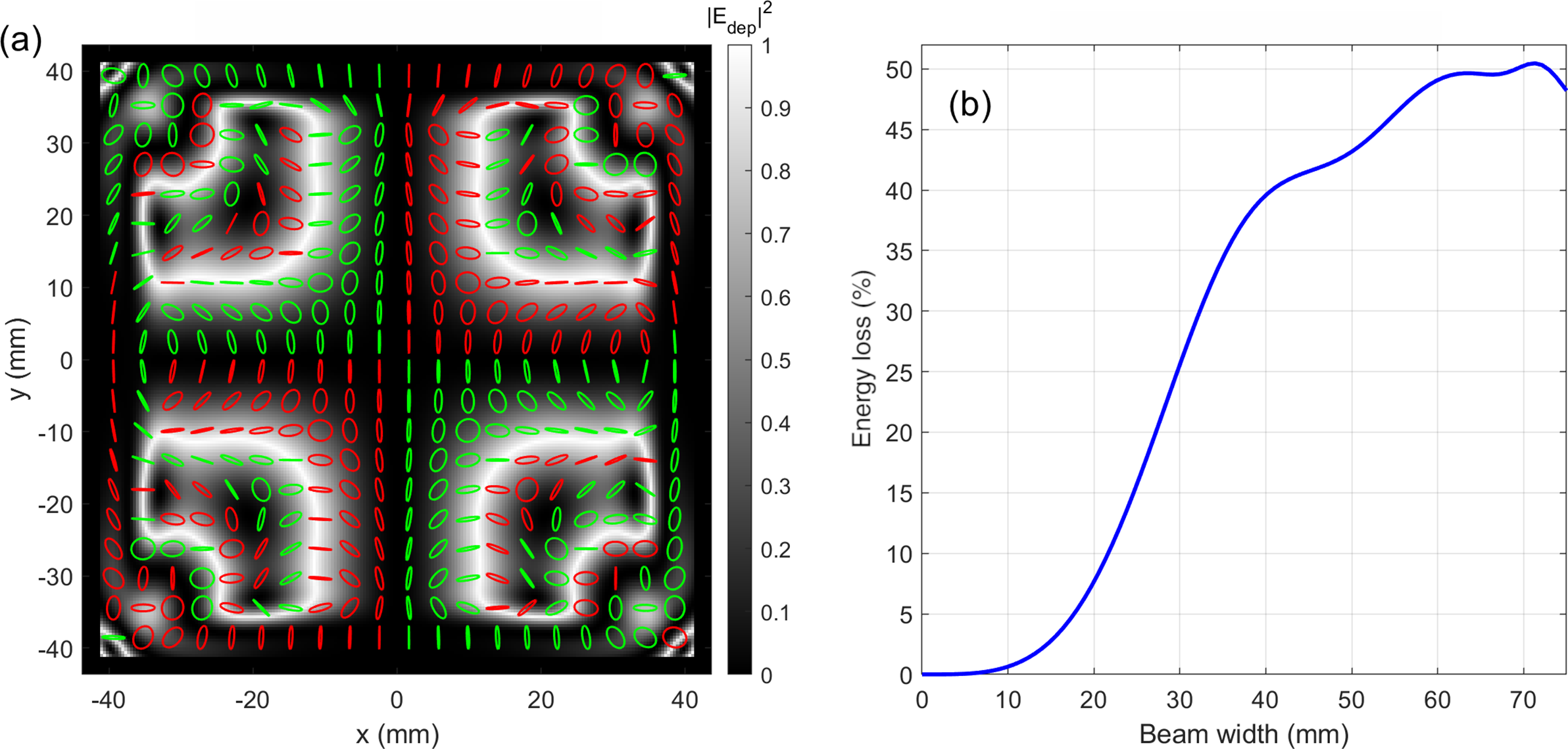
Simulation results for depolarization loss at 1060 nm with linear polarization propagating through a two-amplifier head cavity (as shown in Figure 1) without any compensation mechanism.
3 Results and analysis
Figure 3 shows the estimated depolarization loss for the central wavelength (1060 nm) if no compensation mechanisms are implemented in the cavity. In Figure 3(a) the spatial variation of the local polarization state after two passes is visualized by a grid of polarization ellipses, with green and red ellipses representing right- and left-handed polarization states, respectively. The ellipses are overlaid on a grayscale image of the local depolarization, that is, the energy that is rejected by the polarizer after the second pass, with a value of 1 representing 100% energy loss. Figure 3(b) shows the cumulative integrated energy loss as a function of beam width. The depolarization loss generally increases with the aperture of the beam for a fixed multiplexing angle. Note that the beam after propagating through the two amplifier heads for two passes without any compensation mechanism experiences approximately 50% depolarization-induced energy loss for a 70 mm beam.
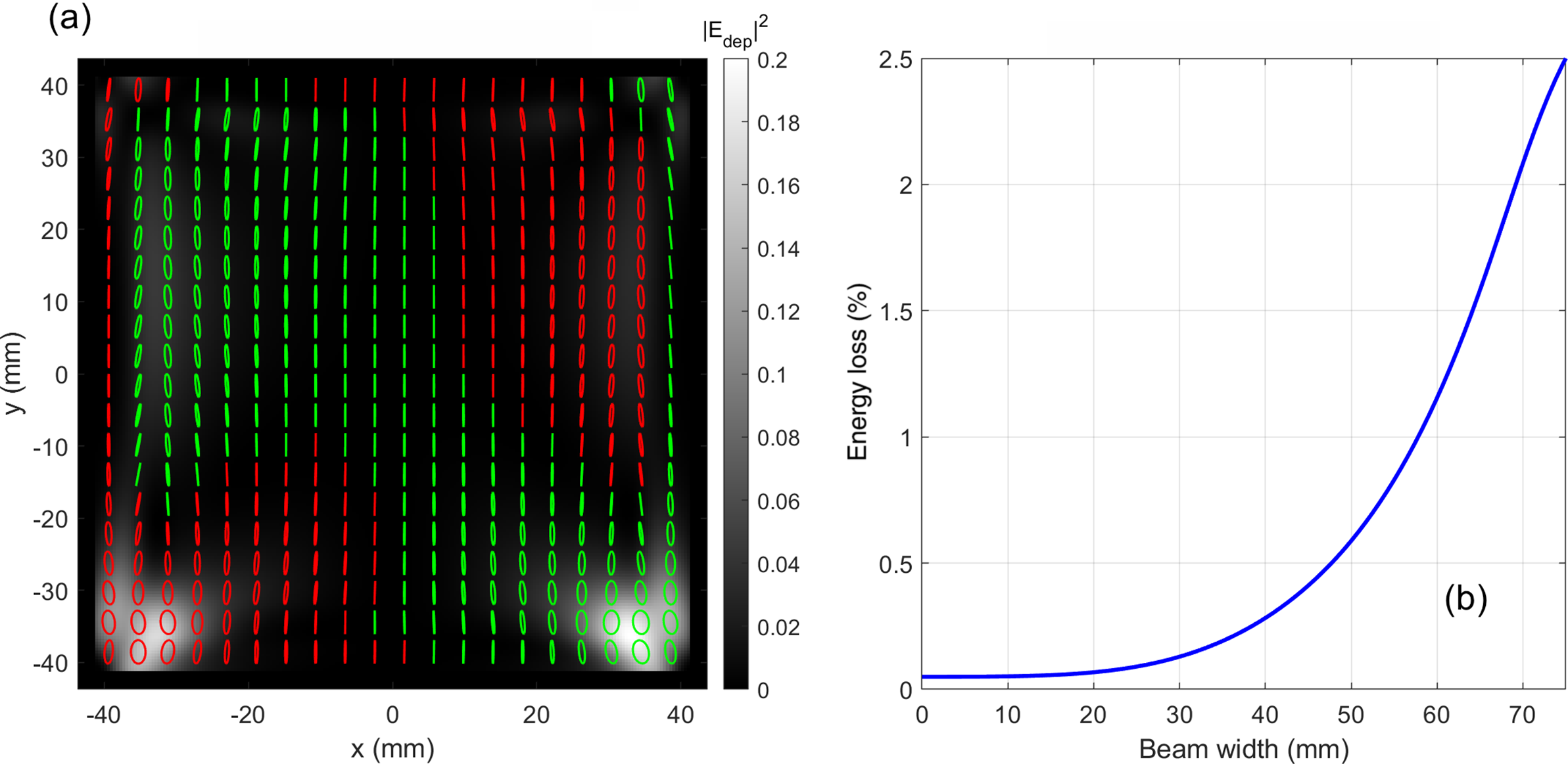
Traditionally, a polarization rotation optic (90° QR) is introduced between two identical amplifier heads to compensate the thermally induced depolarization of the first amplifier with equivalent depolarization of the second. The spatially varying polarization direction exiting the first amplifier is rotated by 90° and propagated through the second amplifier. Figure 4 shows the results of a numerical model for a two-pass cavity with two amplifier heads for the central wavelength only. Although a substantial reduction in depolarization losses is observed with the introduction of a QR between the amplifier heads, the compensation is far from optimized due to the multiplexing angle. Furthermore, even though the model accounts for the multiplexing angle, it assumes perfect alignment, pump uniformity, and no manufacturing imperfections, resulting in identical heat loads and temperature profiles in both the heads, which is not true in a real laser cavity. Depolarization-induced energy loss exceeding 2% is calculated for a 70 mm beam at a 15 mrad multiplexing angle at 1060 nm.
Simulation results for depolarization loss at 1060 nm with a quartz rotator placed between the two amplifiers and cut at a thickness to rotate the central wavelength’s polarization by 90°.
Simulation results for depolarization loss at 1060 nm with a quartz rotator placed inside of both the two amplifiers and cut at a thickness to rotate the central wavelength’s polarization by 90°.
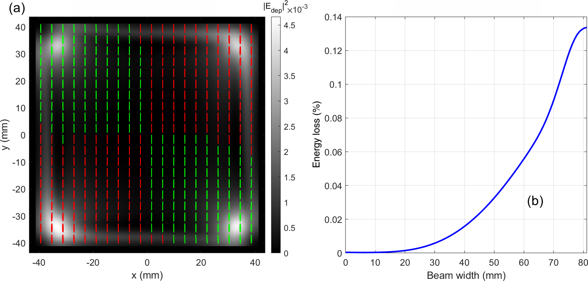
The introduction of QRs inside each amplifier head (instead of a QR placed between the heads), as described by Mason and De Vido[ Reference Mason and De Vido 9 ], further improves the depolarization losses by an order of magnitude. This is owing to the advantage of compensating each amplifier head individually (thermally induced depolarization from the first half of each amplifier head is compensated by its second half). This also reduces the strict requirement of having identical heat loads and temperature profiles between the two amplifier heads. Figure 5 shows the calculated depolarization loss for a 15 mrad multiplexing angle at 1060 nm wavelength only. However, the QRs used inside the amplifier heads have wavelength-dependent rotation of polarization for a fixed thickness (for example, a QR cut for 90° rotation at 1060 nm will have 92.7° rotation at 1045 nm and 87.4° rotation at 1075 nm) and it is important to model the effect of non-optimal polarization rotation at the extremes of the amplified spectrum and predict the depolarization loss at those wavelengths.
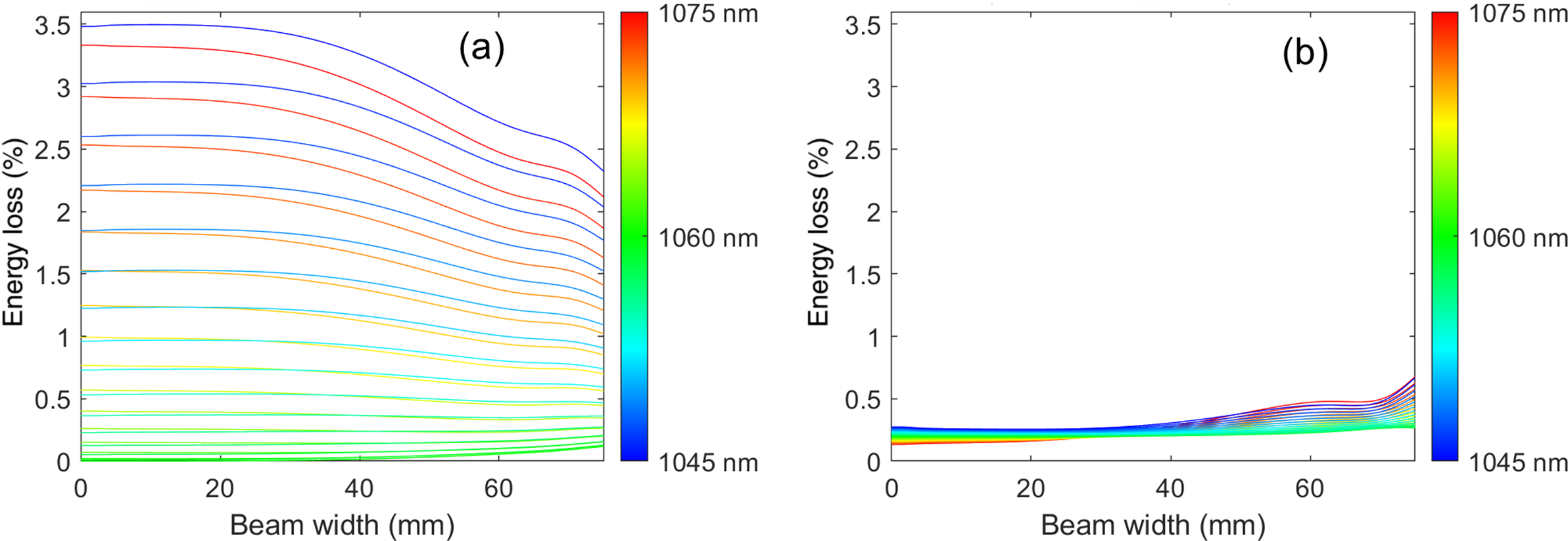
Wavelength dependence of depolarization losses as a function of beam width for wavelengths ranging from 1045 to 1075 nm at 15 mrad multiplexing angle. (a) Both heads contain a right-handed QR. (b) Opposite-handed QRs in the two heads.
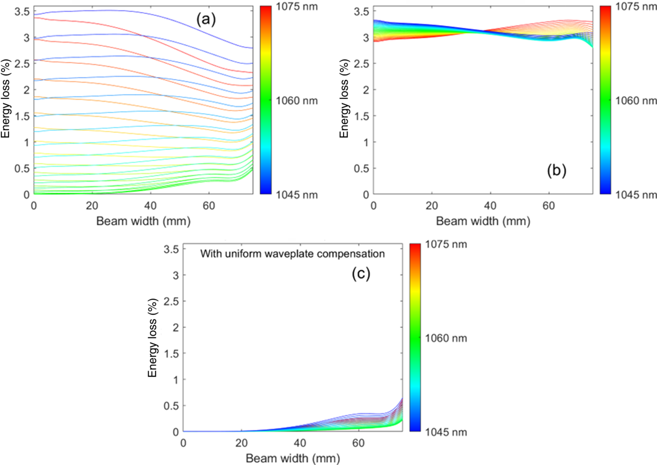
Wavelength dependence of depolarization as a function of beam width for wavelengths ranging from 1045 to 1075 nm at a 30 mrad multiplexing angle. (a) Both heads contain a right-handed QR. (b) Opposite-handed QRs in the two heads. (c) Same case as (b) with additional uniform waveplates for compensation.
A spectrally resolved model was run to understand the wavelength dependence of the QRs and the effect it has on the effectiveness of cavity depolarization compensation. Figure 6 shows the wavelength and beam-width dependent depolarization loss for the cavity when the QRs in the two amplifier heads have the same (Figure 6(a)) or opposite (Figure 6(b)) handedness. Note that the right-handed QRs in both amplifier heads (Figure 6(a)) show significantly higher depolarization losses towards the wings of the spectrum (3.5% at 1045 nm) compared to the central wavelength (0.1% at 1060 nm). This will reduce the useful energy available for experiments and alter the spectral content going to the compressor. However, when a right-handed QR is inserted in head 1 and a left-handed QR is inserted in head 2, the imperfect, ≠90° counterclockwise rotation of polarization by one is compensated by an identical clockwise rotation by the other QR at any given wavelength, thus nearly completely compensating the overall rotation within the cavity for the full spectrum (see Figure 6(b)).
To understand the impact on the depolarization loss with increasing multiplexing angles, the model was re-run with a 2× larger multiplexing angle of 30 mrad (1.72°). Figure 7 shows the modeling results for wavelength-dependent depolarization losses at 30 mrad multiplexing angle. Note that an increase in multiplexing angle introduces an increase of depolarization losses at higher beam sizes for the same-handed QR in both the amplifier heads (Figure 6(a) compared to Figure 7(a)). Furthermore, the longer wavelengths within the spectrum experience lower depolarization losses compared to the shorter wavelengths. This can be attributed to the interaction between the QR rotation and the stress birefringence that the ray experiences as it walks off-axis through the slabs (at high multiplexing angles). Since the stress birefringence has a directional preference (fast and slow axes), it will have different effects on polarization states that are over- or under-rotated by the same amount. It is important to note that with no multiplexing (colinear propagation), the wavelengths at the two extreme ends of spectrum have identical performance.
For the case with opposite-handed QRs in the two amplifier heads, the overall depolarization losses increase from 0.5% to 3.5% for all wavelengths. However, the output polarization is nearly the same for all the wavelengths in the spectrum. Therefore, this static, spatially uniform polarization error can be compensated by a fixed retardation to all spectral components (i.e., by using a combination of achromatic half-wave and quarter-wave plates).
Figure 7(c) shows the result when uniform waveplates are utilized for compensation of the static polarization error for the output shown in Figure 7(b). The same technique will not compensate for the depolarization loss shown in Figure 7(a) as the rotation of polarization changes with wavelength for a same-handed QR in both heads. These modeling results indicate that the utilization of opposite-handed QRs in different heads for a two-head design will compensate thermally induced depolarization for large angular multiplexing angles and large beam sizes compared to using QRs with the same-handedness in both amplifier heads. This is also true for small beam size, rod-type broad-bandwidth amplifiers.
4 Conclusion
In summary, we report on a method for thermally induced depolarization compensation for the generation of high energy, wide bandwidth and high repetition rate simultaneously in a two-head laser amplifier cavity. Theoretical modeling predicts an order-of-magnitude reduction in depolarization losses for the central wavelength when a QR is added in the center of each amplifier head. Further, a spectrally resolved simulation shows significant reduction in the depolarization losses for all wavelengths within the amplified bandwidth when opposite-handed QRs are utilized inside the amplifier heads.
Acknowledgements
This work was performed under the auspices of the U.S. Department of Energy by Lawrance Livermore National Laboratory under Contract DE-AC52-07NA27344, with funding provided by the Department of Energy Office of Fusion Energy Sciences. LLNL-JRNL-869299.


 Open access