





Introduction
A key trend in “5G and beyond technology” lies in the exploitation of high-frequency bands, particularly millimeter-wave (mmWave) frequencies in the range of 24 GHz and above. These bands offer access to vast amounts of undivided spectrum, enabling unprecedented data rates and enhancing the quality of service across a wide range of applications. However, a significant challenge associated with mmWave signals is their poor penetration through materials, which results in severe path loss and consequently heavily limits the link range in both indoor and outdoor-to-indoor (O2I) scenarios [Reference Kodra, Barbiroli, Vitucci, Fuschini and Degli-Esposti1]. Ensuring reliable indoor connectivity at mmWave frequencies has therefore become a critical concern, especially considering that most high-data-rate applications take place indoors and that modern buildings employ thermal and acoustic insulation solutions that further hinder signal penetration. Several innovative approaches have been explored to mitigate these issues. Advanced beamforming techniques, network densification, and the incorporation of active repeaters and antenna-embedded walls [Reference Vähä-Savo, Haneda, Icheln and Lü2, Reference Vähä-Savo, Veggi, Vitucci, Icheln, Degli-Esposti and Haneda3] have been proposed as potential solutions. Nevertheless, one particularly promising approach that has gained significant attention is the use of Reconfigurable Intelligent Surfaces (RISs) [Reference Kitayama, Hama, Goto, Miyachi, Motegi and Kagaya4, Reference Zhang and Blough5].
A RIS is an engineered two-dimensional thin structure composed of a substrate with a distribution of sub-wavelength metallic or dielectric patches (called unit cells) printed on it [Reference Simovski and Tretyakov6]. The shape and size of these patches vary across the surface to achieve the desired effect on the wavefront of the re-radiated wave [Reference Di Renzo, Danufane and Tretyakov7]. By controlling the phase, amplitude, and polarization of the re-radiated wave, RIS enables functionalities that were previously unattainable with natural materials. The real-time reconfigurability of RIS is achieved through the integration of tunable components [Reference Feng, Hu, Qu, Yang, Zheng and Chen8, Reference Merluzzi and Clemente9], thereby positioning RIS-assisted networks as a key enabling technology for future  $6G$ communication systems [Reference Zhu and Huang10].
RIS can either anomalously reflect or transmit (refract) waves based on its configuration. In a reflective RIS, the surface re-radiates the wave toward the intended user when both the base station (BS) and the user are on the same side. In contrast, transmissive RIS is used to transmit a wave through the surface when the BS and user are located on opposite sides, such as in O2I scenarios [Reference Zeng, Zhang, Di, Tan, Han, Poor and Song11]. Although the transmissive mode is important for improving indoor coverage, much of the existing research has primarily focused on reflective RIS [Reference Tang, Chen, Chen, Dai, Han, Di Renzo, Zeng, Jin, Cheng and Cui12–Reference Oliveri, Zardi, Tosi and Massa14]. Only recent studies have started to investigate transmissive RIS and their potential to enhance indoor coverage [Reference Li, Hu, Zhang and Zhang15–Reference Oliveri, Zardi, Gottardi and Massa19]. When strategically positioned on walls or windows, transmissive RIS can concentrate (focus) and reroute the signal through openings toward the desired spot, thereby mitigating signal blockage and offering a promising solution to indoor coverage challenges. The power efficiency of RIS, as reported in several studies [Reference Zhu and Zhou20–Reference Liu, Qi, Che and Yin24], is a key performance metric that quantifies how effectively the surface can direct energy toward a designated point. Reported efficiencies typically range from 40% to 65%, depending on the RIS physical dimension and focal distance. Building on these insights, this work further investigates the feasibility of employing a focusing transmissive RIS for enhancing O2I coverage.
Based on previous work on macroscopic modeling of RIS [Reference Kodra, Vitucci, Barbiroli, Albani and Degli-Esposti25], a realistic RIS is designed and simulated using the macroscopic model in [Reference Kodra, Prete, Bernardi, Fuschini, Barbiroli, Vitucci and Degli-Esposti26] combined with the RIS simulation for O2I coverage improvement. This work investigates the use of ventilation holes – standardized openings in European buildings – as natural locations for embedding RIS/Smart Skins to enhance O2I coverage. It is worth noting that the RIS considered here is not reconfigurable; it is a low-cost, fixed-functionality “Smart Skin,” sufficient to demonstrate the effectiveness of its introduction in enhancing O2I coverage. The O2I coverage is evaluated without and with RIS, using the proposed model in [Reference Kodra, Prete, Bernardi, Fuschini, Barbiroli, Vitucci and Degli-Esposti26]. Furthermore, the feasibility of employing a focusing RIS for O2I coverage enhancement is discussed, with the RIS parameters derived from dedicated electromagnetic simulations of a realistic deployment scenario.
An earlier version of this paper was presented at the 19th European Conference on Antennas and Propagation and was published in its Proceedings [Reference Kodra, Prete, Bernardi, Fuschini, Barbiroli, Vitucci and Degli-Esposti26].
Transmissive RIS
RIS macroscopic modeling
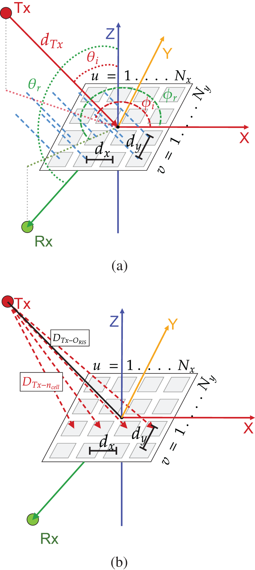
In the reference macroscopic model developed in [Reference Kodra, Vitucci, Barbiroli, Albani and Degli-Esposti25, Reference Degli-Esposti, Vitucci, Renzo and Tretyakov27], the RIS is viewed as a two-dimensional array of antenna elements. Specifically, the surface is divided into  $N_\mathrm{X} \times N_\mathrm{Y}$ elements of area $\Delta S$, each of which can be seen as an aperture antenna that receives an incident power $P_i$ and re-radiates the fraction of it, $P_m$ (see [Reference Kodra, Vitucci, Barbiroli, Albani and Degli-Esposti25, Reference Degli-Esposti, Vitucci, Renzo and Tretyakov27] for more details). The position in space of the generic $n$-th element is defined by the coordinates $(x_n, y_n) = (\Delta l \cdot u, \Delta l \cdot v)$, where $\Delta l$ represents the interspace between the individual elements ( $\simeq \lambda/2$), and $(u, v)$ are the indices identifying them. The reference system used for this work is shown in Fig. 1. RIS is positioned in the $XY$ plane with its center located at the origin. The position of the transmitter (Tx) and receiver (Rx) is defined using spherical coordinates: $( \theta_{i,r}, \phi_{i,r}, d_{Tx,Rx})$ where the angles $\theta_i$, $\phi_i$ and $\theta_r$, $\phi_r$ represent the direction (with respect to the center of the RIS) of incidence and re-radiation, respectively. $d_{Tx}$ is the Tx-RIS distance and $d_{Rx}$ is the Rx-RIS distance.
Reference scheme for an RIS illuminated by an incident wave. In 1(a), under plane wave incidence, traveled distance – and therefore phase – from the Tx to each RIS element varies linearly, whereas in the spherical wave scenario shown in Figure 1(b), traveled distance varies in a non-linear fashion. (a) Incident plane wave. (b) Incident spherical wave.

Figure 1 Long description
The image A shows an incident plane wave on a surface. The surface is divided into elements with coordinates labeled as u equals 1 to N subscript x and v equals 1 to N subscript y. The axes X, Y and Z are marked. The transmitter (Tx) and receiver (Rx) are shown with angles theta subscript i, theta subscript r, phi subscript i and phi subscript r. Distances d subscript x and d subscript y are indicated. The image B shows an incident spherical wave on a similar surface. The transmitter (Tx) and receiver (Rx) are positioned with distances D subscript Tx minus O subscript RIS and D subscript Tx minus n subscript cell. The same axes and element coordinates are labeled as in the first diagram.
Since the RIS aims to re-radiate the incident wave in a desired direction by reducing specular reflection and scattering, it imposes a certain spatial modulation (in phase and in some cases also amplitude ) on the reradiated wave on the surface. In order to obtain the phase shift of the RIS for a given functionality, first, the phase shifts of the incident and desired re-radiated wave need to be determined. In case of an incident plane wave, i.e. when the Tx is farther than the Fraunhofer distance 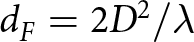 $d_F = 2D^2/\lambda$, with D being the maximum linear dimension of the RIS, the phase of the incident wave at the generic $n$-th element is expressed as:
 \begin{equation}
\chi_{i \, \text{pw}} = \beta\sin(\theta_i)\left( x_n\cos(\phi_i) + y_n\sin(\phi_i) \right),
\end{equation}
\begin{equation}
\chi_{i \, \text{pw}} = \beta\sin(\theta_i)\left( x_n\cos(\phi_i) + y_n\sin(\phi_i) \right),
\end{equation}where  $\beta$ is the wavenumber. Referring to Fig. 1, (1) is obtained considering the following constant phase differences between adjacent antenna elements along the $x$-axis $\Delta \chi_{x}$ and $y$-axis $\Delta \chi_{y}$:
 \begin{equation}
\Delta \chi_{x} = \beta u d_x \sin(\theta_i) \cos(\phi_i),
\end{equation}
\begin{equation}
\Delta \chi_{x} = \beta u d_x \sin(\theta_i) \cos(\phi_i),
\end{equation} \begin{equation}
\Delta \chi_{y} = \beta v d_y \sin(\theta_i) \sin(\phi_i),
\end{equation}
\begin{equation}
\Delta \chi_{y} = \beta v d_y \sin(\theta_i) \sin(\phi_i),
\end{equation} where  $u \in 1, \ldots , N_x$ and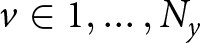 $v \in 1, \ldots , N_y$.
In scenarios where the Tx is closer than the Fraunhofer distance and therefore the plane wave assumption is unacceptable, the incident field phase is calculated using individual distances shown in Fig. 1(b), as:
 \begin{equation}
\chi_{i \, \text{sw}} = - \beta d_{nTx},
\end{equation}
\begin{equation}
\chi_{i \, \text{sw}} = - \beta d_{nTx},
\end{equation}where  $d_{nTx}$ is the distance between Tx and $n$-th element of the RIS.
The macroscopic model used in the present work can efficiently handle both cases of incident waves described above.
Moreover, the phase of the re-radiated wave is calculated based on the desired RIS functionality for the following two different cases:
(1) the case where RIS works as an anomalous reflector re-radiating the wave toward a desired direction. The phase of the re-radiated wave is expressed by:
(5) \begin{equation}
\chi_r = - \beta \sin(\theta_r)(x_n \cos(\phi_r) + y_n \sin(\phi_r))
\end{equation}
\begin{equation}
\chi_r = - \beta \sin(\theta_r)(x_n \cos(\phi_r) + y_n \sin(\phi_r))
\end{equation}(2) the case where RIS works as a focusing lens at a desired near-field reception point. The phase of the re-radiated wave in this case is given by (6):
(6)\begin{equation}
\chi_{r\mathrm{focus}} = -\beta d_{nRx}
\end{equation}


where  $d_{nRx}$ is the distance between Rx and the $n$-th element of the RIS.
Therefore, the phase of the spatial modulation coefficient associated with the  $n$-th element of the RIS for a desired functionality is calculated through the difference between the phase of the re-radiated wave and the phase of the incident wave, as expressed in (7):
 \begin{equation}
\chi_{\text{RIS}} = \chi_{re-radiated} - \chi_{incident},
\end{equation}
\begin{equation}
\chi_{\text{RIS}} = \chi_{re-radiated} - \chi_{incident},
\end{equation}where  $\chi_{re-radiated}$ can be either $\chi_r$ or $\chi_{r\mathrm{focus}}$ depending on RIS functionality and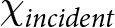 $\chi_{incident}$ can be either $\chi_{i\mathrm{pw}}$ or $\chi_{i\mathrm{sw}}$ depending on if incident wave is plane or spherical.
After obtaining the phase shift generated by RIS, the bilateral power balance in [Reference Kodra, Vitucci, Barbiroli, Albani and Degli-Esposti25] for all the re-radiation modes needs to be satisfied:
 \begin{align}
1=R^2_R \sum_{n=0}^N m_{R_n}+ S^2_{R}\sum_{n=0}^N m_{R_n} \nonumber\\
\quad + R^2_{T} \sum_{k=0}^K m_{T_k} +S^2_{T}\sum_{k=0}^K m_{T_k} + \alpha
\end{align}
\begin{align}
1=R^2_R \sum_{n=0}^N m_{R_n}+ S^2_{R}\sum_{n=0}^N m_{R_n} \nonumber\\
\quad + R^2_{T} \sum_{k=0}^K m_{T_k} +S^2_{T}\sum_{k=0}^K m_{T_k} + \alpha
\end{align} Here  $m_{R}$ and $m_{T}$ are the re-radiation coefficients that determine the fraction of incident power that is re-radiated in one mode in reflection and transmission and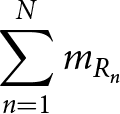 $\displaystyle\sum_{n=1}^N m_{R_n} $ and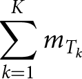 $\displaystyle\sum_{k=1}^K m_{T_k} $ represent the fraction of the total power that is re-radiated for all the modes in the backward (reflection) and forward half-space (transmission), respectively. $\alpha$ is the dissipation parameter that accounts for the percentage of the dissipated power on the substrate, and $R_{T,R}$ and $S_{T,R}$ are the Rayleigh and diffuse scattering coefficients, respectively. In the summations above, the indices $n=0$ and $k=0$ indicate the specular propagating modes.
Once the power balance is satisfied, the total re-radiated field is calculated as the sum of all propagating modes:
 \begin{equation}
E_{\text{tot}}(P) = \sum_{u=1}^{N_x} \sum_{v=1}^{N_y} \Delta E_{m}(P | x_n, y_n)
\end{equation}
\begin{equation}
E_{\text{tot}}(P) = \sum_{u=1}^{N_x} \sum_{v=1}^{N_y} \Delta E_{m}(P | x_n, y_n)
\end{equation}where  $P$ represents the position of the receiver.
Feasibility: Proof of concept for RIS O2I hardware
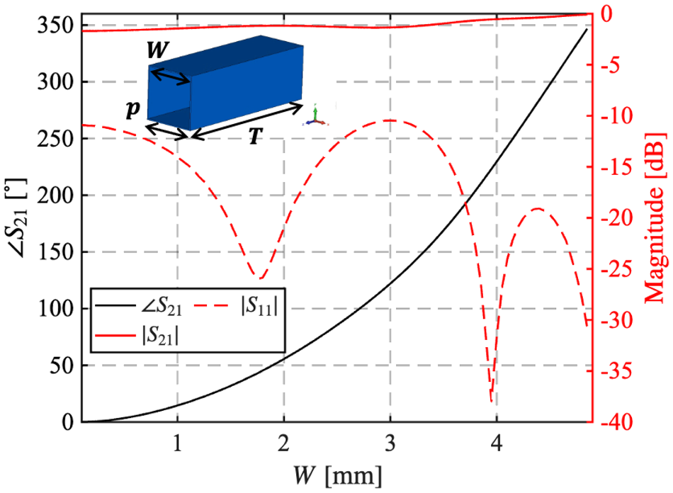
The feasibility of implementing a transmissive RIS for O2I scenarios has been assessed by means of full-wave simulations of realistic, all-dielectric unit cell (UC)-based transmissive surface. This technological choice is motivated by two reasons. First, as already demonstrated in [Reference Massaccesi, Bertana, Beccaria, Marasso, Cocuzza, Dassano and Pirinoli28], such dielectric configurations exhibit a remarkably low dependence on the angle of incidence and ensure that the phase of  $|S_{21}|$ is almost linear over a range of almost $360^{\circ}$. Moreover, all-dielectric cells can be prototyped rapidly with low-cost and easily accessible additive manufacturing techniques. In view of these considerations, a transmissive all-dielectric UC was designed and analyzed.
The selected geometry is the one represented in the inset of Fig. 2: it consists of a perforated square hole UC made of VisiJet M2R-CL, an optically transparent, UV-curable photopolymeric resin, adopted to facilitate architectural integration originally conceived for application to windows, which has already been experimentally characterized in the Ka band [Reference Beccaria, Lupinacci, Massaccesi and Pirinoli29], yielding a relative permittivity of 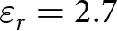 $\varepsilon_r = 2.7$ and a loss tangent of $\tan\delta = 0.017$.
Phase and magnitude of the transmission coefficient  $S_{21}$ and $|S_{11}|$ behavior at 29 GHz. Inset: geometry of the UC.

Figure 2 Long description
The graph displays the phase of the transmission coefficient labeled as left parenthesis angle S subscript 21 right parenthesis in degrees on the left y-axis and the magnitude labeled as vertical bar S subscript 11 vertical bar in decibels on the right y-axis, plotted against the width labeled as W in millimeters on the x-axis. The phase curve is shown in black, starting at 0 degrees and rising to 350 degrees as W increases from 0 to 5 millimeters. The magnitude curve is shown in red, starting at 0 decibels and fluctuating between -10 and -40 decibels as W increases. An inset illustrates a rectangular geometry with dimensions labeled as W, P and T, indicating width, depth and thickness respectively.
The side  $W$ of the central hole is used as the sole degree of freedom to control the response of the cell. The UC periodicity is $p = \lambda_0/2=5\,$mm at the design frequency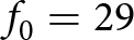 $f_0 = 29\,$GHz in order to avoid grating lobes. The thickness $T$ is the result of a trade-off aimed at simultaneously (i) providing a phase range of variation close to $360^\circ$ and (ii) minimizing the magnitude of the reflection coefficient $|S_{11}|$ over the considered interval of variation for $W$. This choice balances phase agility and matching, yielding low insertion loss and robust manufacturability with the considered resin.
Figure 2 reports the UC response at 29 GHz under normal incidence. The phase  $\angle S_{21}$ exhibits a smooth, nearly monotonic progression with $W$, and covers almost $360^{\circ}$, while the loss remains modest throughout the considered interval, as confirmed by the fact that $|S_{21}|$ is never lower than -1.7 dB, and $|S_{11}|$ never exceeds -11 dB. The analysis has been carried out considering the element embedded in a periodic lattice with CST Microwave Studio™.
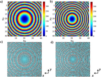
Once the UC has been characterized, two proof-of-concept transmissive RISs have been designed. Although the RIS aims to work as a convex lens, i.e focusing the field impinging field (modeled as a plane wave coming from a BS usually placed in the far-field) in a region close to it, its design can be simplified by exploiting the fact that the transmissive surface is a reciprocal device. In view of this, the RIS can be considered as a transmitarray (TA), with the source of the incident field located in the focus of the RIS, designed to radiate in the direction of arrival of the plane wave impinging on the RIS. In both the considered cases, the surface is a square aperture with side 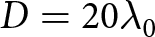 $D = 20\lambda_0$, discretized with $40\times40$ UCs. The lenses were synthesized to radiate a broadside beam when two different focal distances,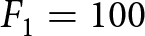 $F_1 = 100\,$mm and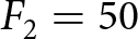 $F_2 = 50\,$mm are considered. They correspond to the ratios of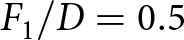 $F_1/D = 0.5$ and $F_2/D = 0.25$, respectively. The feeding point is centered with respect to the transmissive surface.
In Fig. 3(a) and (b), the maps of the required phase distributions for the two configurations are shown, while Fig. 3(c) and (d) present the corresponding layouts.
Phase distributions (top) and corresponding layouts (bottom) of the all-dielectric transmissive RIS at 29 GHz: (a) and (c)  $F_1/D=0.50$. (b) and (d) $F_2/D=0.25$.

Figure 3 Long description
The image A shows a phase distribution map with concentric circular patterns labeled 'Nx' and 'Ny', with values ranging from 0 to 500. The image B shows a similar phase distribution map with values ranging from 0 to 300. The image C shows a layout with a grid pattern labeled 'x' and 'y', corresponding to the phase distribution in image A. The image D shows another layout with a grid pattern labeled 'x' and 'z', corresponding to the phase distribution in image B.
For each design, the radiation efficiency  $\eta_{rad}$ has been evaluated using the standard feed-to-plane configuration in CST Microwave Studio. This metric isolates the material and ohmic losses and is therefore the relevant parameter for the analytical model used in this work.
Table 1 highlights a robust frequency behavior of the radiation efficiency over the considered band, with variations of only a few points. A slightly lower  $\eta_{rad}$ is observed for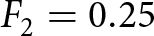 $F_2 = 0.25$ compared with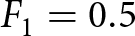 $F_1 = 0.5$. This is expected: focusing the field closer to the transmitting surface requires a greater number of phase jumps, which involves steeper phase transitions from one cell to another, resulting in a break in local periodicity, which in turn causes a slight reduction in radiation efficiency. However, the limited reduction in efficiency confirms the validity of the analytical model considered in this work. $\eta_{rad}$ vs focal ratios and frequency behavior

Table 1 Long description
The table measures radiation efficiency at different focal ratios and frequencies. At a focal ratio of 0.5, the efficiency is highest at 29 GHz and decreases slightly as frequency increases to 31 GHz. Similarly, at a focal ratio of 0.25, efficiency is highest at 29 GHz and decreases at higher frequencies. Comparing the two focal ratios, the efficiency is consistently higher at 0.5 than at 0.25 across all frequencies. This suggests that a higher focal ratio may lead to better radiation efficiency, although the efficiency decreases with increasing frequency for both ratios.
Use case and discussion
To evaluate the impact of RIS on indoor coverage, the authors propose to take advantage of the ventilation holes commonly found in European buildings, serving to ensure air flow in kitchens, boiler rooms, and windowless bathrooms. According to the Italian standard UNI 10738 [30], each ventilation opening must measure at least  $10\,cm\times10\,cm$ – or, if circular, have a diameter of at least 11.3 cm. Their consistent presence and standardized sizing make such openings excellent locations for integrating RIS with minimal structural disruption (refer to Fig. 4 for the schematic setup). To assess their effectiveness, a comparative O2I study is conducted using ray tracing (RT) simulations at 29 GHz considering two cases: one without RIS and one with RIS. The detailed simulation parameters are summarized in Table 2.
Schematic simulation scenario with RIS.

Figure 4 Long description
The diagram illustrates a base station on the left transmitting signals towards a building on the right. Between the base station and the building, a RIS panel is positioned, redirecting the signals. The signals are shown as waves moving from the base station to the RIS panel, which then reflects and redirects them towards the building. The building facade is depicted with a grid pattern and the signals are shown entering through a highlighted section, indicating the point of reflection and redirection. Arrows illustrate the direction of the redirected signals within the building.
Simulation parameters
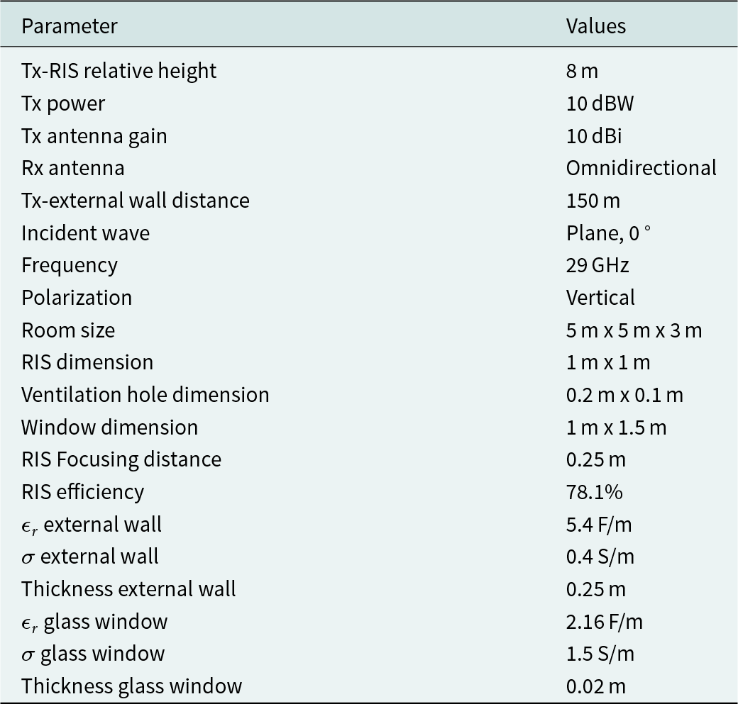
Table 2 Long description
The table outlines various simulation parameters for a wireless communication setup. Key data points include a transmitter power of 10 decibel watts and a transmitter antenna gain of 10 decibels isotropic. The receiver antenna is omnidirectional, and the incident wave is plane with zero degrees angle. The room measures 5 meters by 5 meters by 3 meters, while the RIS dimension is 1 meter by 1 meter. The RIS efficiency is noted at 78.1 percent. Comparatively, the external wall has a relative permittivity of 5.4 farads per meter and a conductivity of 0.4 siemens per meter, whereas the glass window has a relative permittivity of 2.16 farads per meter and a conductivity of 1.5 siemens per meter. The thickness of the external wall is 0.25 meters, and the glass window is 0.02 meters thick.
Case without RIS
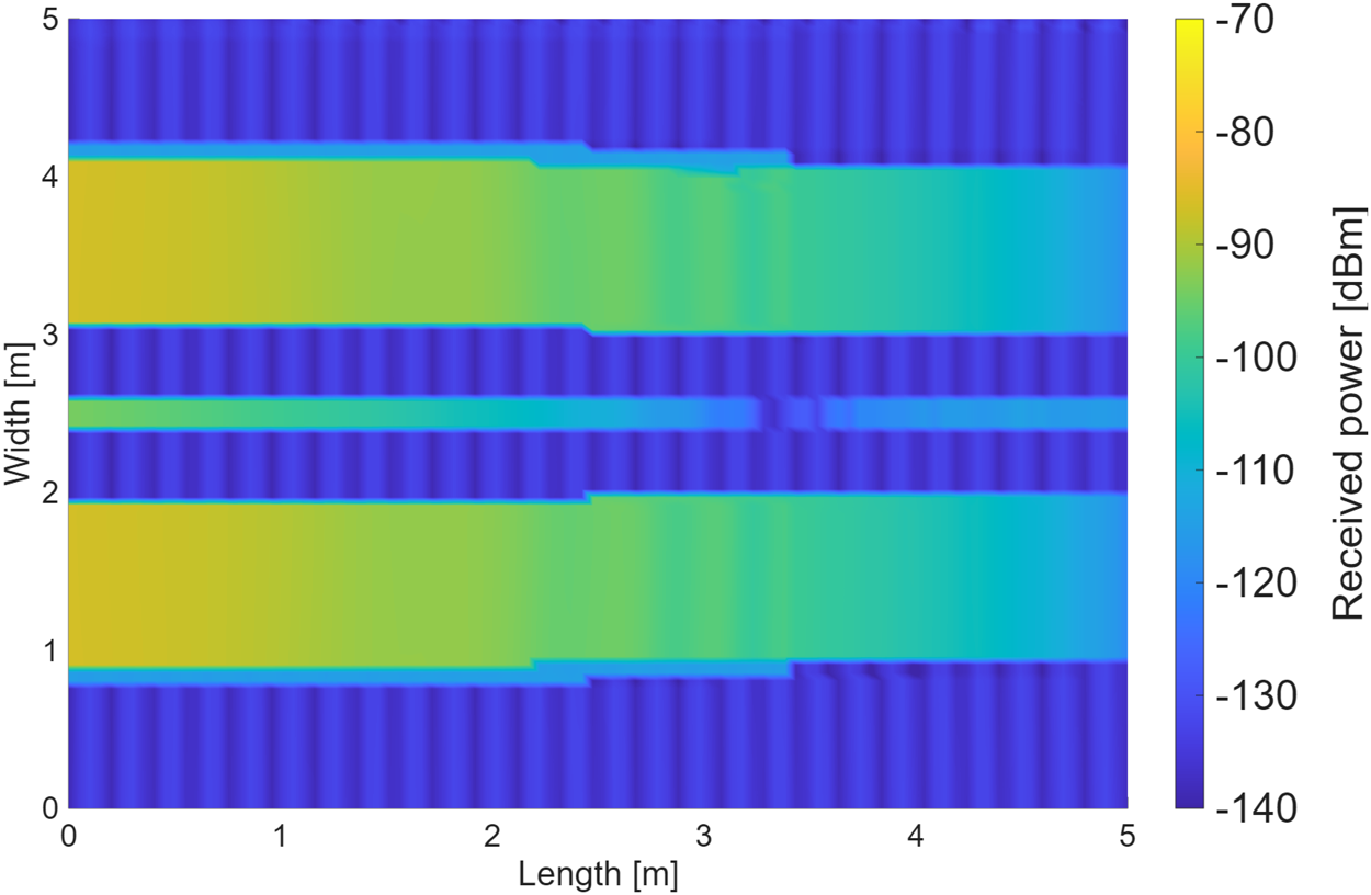
In the first scenario, the RT simulation between Tx and Rx was performed without the presence of RIS. The Tx was placed in the far field (quasi-normal plane wave incidence), illuminating the external wall of a building composed of a room only for simulation overhead reduction. The façade was initially modeled without windows and subsequently modified to include them (see Table 2 for window details), ensuring a more realistic representation of typical building conditions. A dense grid of receivers at different heights was placed inside the room in order to obtain insight into the received power throughout the room. The external wall is a brick wall with its permittivity and conductivity taken from [31]. A central ventilation hole is present in the external wall at a height of 40 cm from the floor, representing a realistic position. The objective of this simulation was to evaluate signal penetration through the wall and its spatial distribution within the indoor environment. Figure 5 illustrates the received power inside the room, including the presence of windows, at a height of  $1 m$ from the floor, which corresponds to a typical user height. As seen from Fig. 5, it was confirmed that the indoor received power in the case of no RIS was notably low (in most locations below -90 dBm), with a higher received power only in the region directly in front of the ventilation hole and the windows. This behavior results from the rays entering the room through these openings from the Tx. The high attenuation elsewhere in the room is due to the high attenuation of the external wall at 29 GHz.
Indoor coverage without RIS (room with windows).

Figure 5 Long description
A heatmap illustrating received power in decibels-milliwatts across a 5 by 5 meter area. The x-axis is labeled ‘Length’ in meters, ranging from 0 to 5. The y-axis is labeled ‘Width’ in meters, also ranging from 0 to 5. The color scale on the right indicates received power levels from negative 140 to negative 70 decibels-milliwatts, with variations in color representing different power levels across the area.
Case with RIS
In the second scenario, a RIS was integrated into the RT simulation discussed above, combining it with the model described in Section II.
The proposed approach exploits small ventilation holes commonly found in most European buildings by placing a focusing RIS on the external part of the wall. Thanks to the phase profile generated according to Section II, the RIS collects the impinging power and focuses it toward the center of the ventilation hole, using a power efficiency value of  $78.1\%$ as given in Table 1 for the frequency of interest. After propagation through the hole (properly coated with a metal film waveguide), the wave spreads into the indoor environment, therefore offering enhanced coverage compared to the scenario without RIS. The simulation scenario is illustrated in a schematic way in Fig. 4. The dimensions of the RIS, the ventilation hole, and the focusing distance from the RIS surface were chosen with careful consideration in order to reflect realistic conditions and practical fabrication limitations for a low-cost RIS realization (refer to Table 2 for more details). However, it is important to mention that with very advanced manufacturing techniques, much larger Smart Skins (even $2\,m^2$) could be produced, leading to greater performance in terms of coverage improvement. Furthermore, although the present study focuses on a fixed-functionality Smart Skin, the proposed parametric model in Section II and its integration within the RT framework are inherently independent of the specific surface implementation. Reconfigurability can be naturally accommodated by updating the surface parameters for each configuration, without requiring any modification to the underlying formulation.
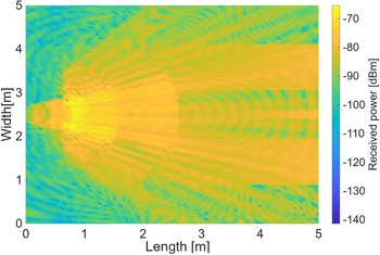
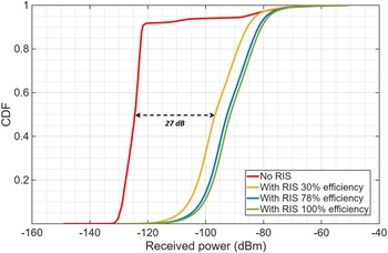
Figure 6 shows the received power distribution at a height of  $1\,m$ from the floor when RIS is used in a room with windows. It can be observed that RIS effectively spreads coverage into the room in a fan-shaped area, creating a well-covered region (around -70 dBm) near the center of the $x$-coordinate of the room that is aligned with the position of the ventilation hole. As expected, power decreases with distance from the focal point, showing a smooth gradient toward the edges of the room. Figure 7 shows the Cumulative Distribution Functions (CDF) of the received power obtained from the 3D grid of receivers placed throughout the room without windows. The CDFs are presented for the cases without RIS and with RIS considering three different power efficiencies: 30% (as already discussed in [Reference Kodra, Prete, Bernardi, Fuschini, Barbiroli, Vitucci and Degli-Esposti26]), 78.1% (as proposed in Section II B), and the ideal case of 100%. It can be observed that in the case with RIS, the overall received power is around 27 dB higher and more uniform across the environment. On the contrary, without RIS, coverage is confined to the area directly aligned with the ventilation hole, where the direct path from the BS exists. This is reflected by the higher probability of receiving power below -140 dBm. At high CDF values, the curves converge because those correspond to receiver points directly after the ventilation hole, where the direct Tx-Rx rays dominate, and the gain of the RIS becomes negligible compared to the strong direct signal.
Indoor coverage with RIS (room with windows).

Figure 6 Long description
A heatmap illustrating the received power distribution in a room. The x-axis is labeled ‘Length’ in meters, ranging from 0 to 5. The y-axis is labeled ‘Width’ in meters, also ranging from 0 to 5. The color scale on the right indicates received power in decibels milliwatt, ranging from negative 70 to negative 140. The distribution forms a fan-shaped pattern, with higher power levels concentrated near the center and decreasing towards the edges.
Power CDF with and without the RIS (room with no window).

Figure 7 Long description
A graph showing the Cumulative Distribution Function (CDF) of received power in decibel-milliwatts (dBm) with and without Reconfigurable Intelligent Surface (RIS). The x-axis is labeled ‘Received power (dBm)’ ranging from negative 160 to negative 40. The y-axis is labeled ‘CDF’ ranging from 0 to 1. Four curves are plotted: ‘No RIS’ in red, ‘With RIS 30 percent efficiency’ in orange, ‘With RIS 78 percent efficiency’ in green and ‘With RIS 100 percent efficiency’ in blue. The graph indicates a 27 dB difference in received power between the ‘No RIS’ and ‘With RIS’ scenarios. The curves with RIS show higher received power and more uniform distribution compared to the ‘No RIS’ curve, which is confined to lower power levels.
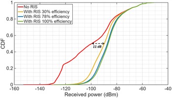
Figure 8 presents the corresponding CDFs for the scenario with windows included in the façade. In this case, the overall received power increases for both the RIS and non-RIS configurations due to the additional transmission paths provided by the glass openings. Nevertheless, the gain achieved with the RIS remains evident, though less pronounced than in the windowless case, since part of the signal already penetrates through the windows. The RIS still contributes to a higher and more uniform power distribution inside the room. At high CDF values, the curves converge, as in the case of the room with no windows. However, for both the case with and without windows, the gain in coverage from 30% to 78.1% in the RIS efficiency is around 3–4 dB, while the difference between 78.1% and the ideal 100% case is negligible, indicating that near-optimal focusing performance can already be achieved with a realistic fabrication.
Power CDF with and without the RIS (room with window).

Figure 8 Long description
A graph showing the cumulative distribution function (CDF) plotted against received power measured in decibels-milliwatts (dBm). The x-axis is labeled ‘Received power (dBm)’ ranging from negative 160 to negative 40 and the y-axis is labeled ‘CDF’ ranging from 0 to 1. Four curves are depicted: a red curve for ‘No RIS’, a yellow curve for ‘With RIS 30 percent efficiency’, a blue curve for ‘With RIS 78 percent efficiency’ and a green curve for ‘With RIS 100 percent efficiency’. The curves show how the received power changes with different RIS efficiencies, with a noted difference of 11 decibels between certain curves. The graph illustrates the impact of RIS on power distribution efficiency.
The main focus of this study is to propose a new approach to indoor coverage improvement by the aid of a RIS/Smart-Skins and to compare performance in a simple case with and without the integration of RIS. Looking ahead, the development of modern buildings with low thermal emission and highly insulating materials is expected to further hinder mmWave propagation. As a result, the use of RIS or Smart-Skin technology can be considered a promising and cost-effective solution to mitigate these future propagation issues and enhance indoor signal penetration.
Conclusions
In this work, a realistic RIS has been designed and simulated to demonstrate its capability to enhance O2I coverage by focusing the impinging field through a ventilation opening. The proposed all-dielectric transmissive surface, designed for architectural compatibility and high power efficiency, was modeled using the macroscopic model proposed in this work and was integrated into an RT simulation to assess its impact on indoor coverage. The results show that strategically placing a focusing RIS over a ventilation hole can increase the average indoor received power by several tens of dBs. The improvement is particularly evident in scenarios without windows, where the RIS effectively compensates for the lack of natural transmission paths. Moreover, the analysis of different power efficiencies shows that increasing the RIS efficiency from 30% to 78.1% results in a coverage gain of about 3–4 dB, while the difference between 78.1% and the ideal 100% case is negligible, confirming that near-optimal focusing can be achieved under realistic design conditions. Future work will extend the analysis to more realistic building layouts as well as the electromagnetic synthesis of suitable RIS microstructure for the realization of large-scale intelligent skins with low focal lengths and practical implementation constraints.
Funding statement
This work was supported in part by the European Union - Next Generation EU under the Italian National Recovery and Resilience Plan (NRRP), Mission 4, Component 2, Investment 1.3, CUP.J33C22002880001, partnership on “Telecommunications of the Future” (PE00000001 - program “RESTART”), in part by the Italian Ministry of University and Research (MUR) within the framework of the PRIN 2022 project INSIDE-NEXT (“INdoor Smart Illuminator for Device Energization and Next-generation communicaTions”), CUP.J53D23000900006, in part by the EU Project 6G-SHINE (6G short range extreme communication in entities), Horizon Europe Programme, Grant No. 101095738, and in part by the EU COST Action INTERACT (Intelligence-Enabling Radio Communications for Seamless Inclusive Interactions), Grant CA20120.
Competing interests
The author(s) declare none.

Silvi Kodra received the M.Sc. degree in telecommunications engineering from the University of Bologna and the M.Sc. degree in electronics and communication engineering from Tongji University, Shanghai. She also got her Ph.D. degree in Telecommunications Engineering with the University of Bologna in March 2025. She has served as the young researcher representative for COST CA20120 Interact from 2024 to 2025. Her activity is focused on the research topic in reconfigurable intelligent surfaces, channel characterization for mm-wave and sub-THz frequencies, and propagation losses in indoor environments. She is currently involved as Student Chair in the organization of several conferences.

Elena Bernardi received the B.S. degree in electronics engineering and the M.S. degree in electronics and telecommunications engineering, in 2019 and 2022, respectively, from the University of Bologna, Italy, where she is currently pursuing the Ph.D. degree in electronics, telecommunications and information technologies engineering. From 2022 to 2025, she was with the National Inter-University Consortium for Telecommunications, Wireless Laboratory (WiLab), working on massive multiple access and channel characterization at mmWave and subTHz. Her research interests include channel propagation analysis, measurements across different propagation environments, ray tracing, and reconfigurable intelligent surfaces.

Franco Fuschini received the M.Sc. degree in telecommunication engineering and the Ph.D. degree in electronics and computer science from the University of Bologna, Italy, in March 1999 and July 2003, respectively. He is currently an Associate Professor with the Department of Electrical, Electronic and Information Engineering “Guglielmo Marconi,” University of Bologna. He has authored or coauthored more than 50 journal articles on electromagnetic wave propagation and wireless systems design. His main research interests are in the area of radio systems technologies, radio propagation theoretical modeling, and experimental investigation. In April 1999, he received the “Marconi Foundation Young Scientist Prize” in the context of the XXV Marconi International Fellowship Award.

Marina Barbiroli received the Laurea degree in Electronic Engineering and the Ph.D. degree in Computer Science and Electronic Engineering at the University of Bologna, in 1995 and 2000, respectively. She is currently an Associate Professor at the Department of Electrical, Electronic and Information Engineering “G. Marconi” of the University of Bologna. Her research focuses on radio system design through theoretical and experimental modeling of the wireless propagation channel. The research activity includes participation in European research and cooperation programs.

Enrico Maria Vitucci (Senior Member, IEEE) is currently an Associate Professor in applied electromagnetics, antennas, and propagation with the Department of Electrical, Electronic and Information Engineering “Guglielmo Marconi,” University of Bologna, Italy. He is the Head of the Cesena-Forli Unit of the Center for Industrial Research on ICT (CIRI-ICT) of the University of Bologna. In 2007, he was a Visiting Scholar at Aalto University, Finland. From 2015 to 2016, he was an Invited Researcher at Polaris Wireless, Inc., Mountain View, CA, USA. He is the author of more than 140 technical articles in international journals and conferences, and co-inventor of 5 international patents. He is a Senior Member of the IEEE and a Senior Member of the International Union of Radio Science (URSI). He served as Academic Editor, Associate Editor, and Guest Editor for several international journals. He participated in the European research and cooperation actions COST 2100, COST IC1004, COST IRACON, and COST INTERACT, in the European Networks of Excellence NEWCOM and NEWCOM++, and in several EU projects of the FP7, H2020, and Horizon Europe programmes. He has been appointed as a Teacher in several editions of the courses on Mobile Radio Propagation and Short-Range Propagation of the European School of Antennas (ESoA). His research interests are in deterministic and hybrid wireless propagation modeling, machine learning applied to radio propagation, macroscopic electromagnetic models for metasurfaces/RIS, and dynamic ray tracing techniques for high-mobility radio channels.

Paola Pirinoli (Member, IEEE) received the M.S. (Laurea) and Ph.D. (Dottorato di Ricerca) degrees in Electronic Engineering from the Politecnico di Torino, Italy, in 1989 and 1993, respectively. Since 2018, she has been a Full Professor in the Department of Electronics and Telecommunications of Politecnico di Torino. She was a Visiting Research Fellow at the University of Nice (F) from 1996 to 1997 and at Tsinghua University, Beijing (China) from 2014 to 2015. She is a Member of the board of the IEEE AP/ED/MTT North Italy Chapter, and a Member of the TPC and the organizing committee of several international conferences. She serves as a Reviewer for several international journals and conferences. Her most recent research activities include the development of innovative and efficient global optimization techniques, particularly suitable for the optimized design of antennas and microwave circuits; the design of planar and conformal reflective/transmitting surfaces, working from microwave to sub-THz frequencies, and designed resorting to both conventional and additive manufacturing techniques. In 2000, she received the Best AP2000 Oral Paper on Antennas Prize at the Millennium Conference on Antennas and Propagation, and in 1998, she was the recipient of a URSI International Young Scientist Award at the URSI International Symposium on Electromagnetic Theory, and of the Barzilai Prize for the Best Paper at the National Italian Congress of Electromagnetic (XII RiNEm).

Michele Beccaria (Member, IEEE) received the B.Sc., M.Sc., and Ph.D. degrees (cum laude) in Electrical, Electronic, and Telecommunication Engineering from Politecnico di Torino, Italy, in 2013, 2015, and 2019, respectively. Since 2023, he has been an Assistant Professor with the Department of Electronics and Telecommunications at Politecnico di Torino, where he was previously a Research Fellow from 2019 to 2022.
In February 2026, he was appointed as an Associate Professor (Maitre de Conférences) at Télécom SudParis (Institut Mines-Télécom, Institut Polytechnique de Paris), France.
His research interests include the design, optimization, and manufacturing of advanced reflectarrays, transmitarrays, and smart electromagnetic surfaces.
From 2017 to 2018, he was a Visiting Researcher at Tsinghua University, Beijing, China, under the supervision of Prof. Fan Yang. Dr. Beccaria has coauthored more than 60 scientific publications, including journal papers, conference proceedings, and invited book chapters. He is regularly involved in major international conferences, such as the IEEE International Symposium on Antennas and Propagation (AP-S/URSI), the USNC-URSI Radio Science Meeting, and the European Conference on Antennas and Propagation (EuCAP). He was the recipient of several awards, including the 2019 IEEE AP/ED/MTT North Italy Chapter Best Ph.D. Thesis Award (Antennas and Propagation Society), the TICRA Travel Grant for EuCAP 2025, and the 2025 Young Scientist Award from URSI Commission B.
He has served on the Technical Program Committee of the IEEE International Conference on Communications and Electronics (ICCE) since 2018 and is currently an Editorial Board Member of Scientific Reports (Nature Portfolio).

Vittorio Degli Esposti (Senior Member, IEEE) is currently a Full Professor with the Department of Electrical Engineering of the University of Bologna. He was a Post-Doc at Brooklyn Polytechnic University (now NYU Tandon School of Engineering), Visiting Professor at Aalto University, Finland, in 2006, at Tongji University, China, in 2013, and Director of Research at Polaris Wireless Inc., USA, from 2015 to 2016. He has been General Chair of the conference URSI EMTS 2025, Vice-Chair of EuCAP2010 and EuCAP 2011, Short-Course and Workshops Chair of EuCAP 2015, and Convened Sessions Chair of EuCAP 2023. He is Co-Chair of the Working Group WG1 “Radio Channels” of the European COST Action 20120 “Interact.” He is an Editor for the IEEE Transactions on Vehicular Technology. He has authored or coauthored more than 170 peer-reviewed technical papers and is a co-inventor of 7 international patents in the fields of applied electromagnetics, radio propagation, and wireless systems. He was the recipient of the “2023 EurAAP Propagation Award.”









 Open access

