


1. Introduction
Shock waves are mechanical waves that move supersonically with respect to the fluid ahead of them and across which flow properties change abruptly. They play a dominant role in most mechanical flow problems characterised by high-rate drive. Their existence has been observed in a wide range of scales, from microscopic structures to astronomic events and in the four states of matter (Glass Reference Glass1974; Krehl Reference Krehl2009; Fortov Reference Fortov2021). A deep understanding of how these sudden compressions form, evolve and interact with the surrounding flow and the shocked medium has been pivotal in the progress of many areas, including aerodynamics, propulsion, detonation science, ballistics, inertial confinement fusion or astrophysics, to name a few.
In most practical applications that involve high-Mach-number shocks, the flow is seldom free from disturbances as these perturbations can arise from various sources, including the inlet conditions, the presence of boundary layers, surface roughness or other imperfections. Then, it is natural to wonder whether these disturbances can affect the shock front dynamics and ultimately trigger an instability in the shock evolution, producing a wrinkled or rippled shock front shape or its decomposition into other flow structures. The shock fronts in atmospheric air and shock pressures accessible with supersonic projectiles, such as bullets or shock tubes, turned out to be stable, which means that perturbations of their shape decay with time. This is evidenced by the remarkably smooth and regular shapes of observed shock fronts, starting from the earliest images of shock fronts in the air recorded by Mach & Salcher (Reference Mach and Salcher1887). This is true even when the supersonic flow producing the shock wave is very non-uniform, such as the rupture of the diaphragm in a shock tube, see figure 66 in Glass (Reference Glass1974). Shock stability theoretical studies started in the 1940s (Roberts Reference Roberts1945; Freeman Reference Freeman1955; Zaidel’ Reference Zaidel’1960; Nikolaev Reference Nikolaev1965) established that the ripples on a planar steady shock front driven by a piston into a uniform ideal gas with a constant adiabatic exponent  $\gamma$ decay with time as $t^{-3/2}$, or $t^{-1/2}$ in the strong-shock limit. The consideration of nonlinear disturbances may lead to different results in what concerns the evolution of a corrugated planar shock, see Majda & Rosales (Reference Majda and Rosales1983), Clavin (Reference Clavin2013) and Clavin & Searby (Reference Clavin and Searby2016). Recent studies, such as those conducted by Lodato, Vervisch & Clavin (Reference Lodato, Vervisch and Clavin2016) and Shen et al. (Reference Shen, Pullin, Samtaney and Wheatley2021), have examined planar shocks driven by a weakly nonlinear corrugated piston moving in an ideal gas. These studies have found that the shock may undergo a transformation that leads to the formation of triple points, which propagate in the transverse direction at a phase velocity that is similar to the speed of sound in the shocked gas. If the initial disturbances are small enough, the linear ideal-fluid theory remains valid within its applicable range since the emergence time of the Mach stems from the triple points is inversely proportional to the initial shock corrugation amplitude.
If the shocked material's equation of state (EoS) differs from that of an ideal gas, then the stability of the shock front cannot be guaranteed as the shape of the Rankine–Hugoniot (RH) curve, which sets the stability boundaries, varies according to the EoS, as explained in the following. The shock-front instability criteria were derived in the pioneering works of D'yakov (Reference D'yakov1954) and Kontorovich (Reference Kontorovich1957). They identified two possible kinds of instability. For one, D'yakov and Kontorovich (DK) predicted an exponential growth of perturbations, whereas the other featured a neutral stability. The latter is referred to as a special form of shock wave instability, ‘although there is here no instability in the literal sense: the perturbation (ripples), once created on the surface, continues indefinitely to emit waves without being either damped or amplified’ Landau & Lifshitz (Reference Landau and Lifshitz1987), and for this specific property this regime is also coined spontaneous acoustic emission (SAE). As Landau & Lifshitz (Reference Landau and Lifshitz1987) noted, SAE implies that the reflection coefficient of the sonic waves incident on the shock front from downstream becomes infinite for certain values of the incidence angle. This is an important aspect to consider as undamped sonic waves that are reflected from the shock greatly enhance acoustic coupling, leading to a significant amplification of the supporting mechanism's influence on shock dynamics.
A necessary but not sufficient condition for the shock stability, which must be satisfied for any EoS, is that it has to be evolutionary, i.e. the upstream and downstream Mach numbers in the shock-stationary reference frame must satisfy  ${\mathcal {M}}_1>1$ (supersonic upstream) and ${\mathcal {M}}_2<1$ (subsonic downstream), respectively. The EoS-dependent stability criteria are expressed via the DK parameter
 \begin{equation} h=\left. \frac{p_2-p_1}{V_1-V_2}\frac{{\rm d} V_2}{{\rm d} p_2}\right|_{RH} =\left.-u_2^2\dfrac{\partial \rho_2}{\partial p_2}\right|_{RH}={-}\dfrac{\tan \beta_{RM} }{\tan \beta_{RH}} \end{equation}
that measures the slope of the RH curve ( $\beta _{RH}$) (later referred to simply as Hugoniot) relative to the Rayleigh–Michelson straight line ( $\beta _{RM}$) on the $\{V,p\}$ plane, as depicted in figure 1. Here, $p$,
$p$,  $\rho$, $V=1/\rho$ and $u$ denote the pressure, density, specific volume and fluid velocity with respect to the shock front, respectively, subscripts 1 and 2 refer to pre- and post-shock states, and the derivatives are calculated along the Hugoniot curve with the pre-shock pressure and density fixed. For an ideal-gas EoS, $h=-1/{\mathcal {M}}_1^2$, which means that $h$ is bounded by $-1$ and $0$ in the weak and strong shock limits, respectively. For different EoS, we refer to the appendix in Huete et al. (Reference Huete, Velikovich, Martínez-Ruiz and Calvo-Rivera2021), where the evaluation of the function $h$ is done for a van der Waals (vdW) EoS and for the three-term EoS for simple metals, including aluminium and copper.

Figure 1. Qualitative example of an arbitrary RH curve. The angles of the RH curve  $\beta _{RH}$ and the Rayleigh–Michelson line $\beta _{RM}$ are identified.
Stability of the shock front is predicted if  $-1< h< h_c$, where
 \begin{equation} h_c = \dfrac{1-{\mathcal{M}}_2^2\left(1+{\mathcal{R}}\right)}{1-{\mathcal{M}}_2^2\left(1-{\mathcal{R}}\right)}, \end{equation}
and  ${\mathcal {R}}=\rho _2/\rho _1$ is the shock density compression ratio. Shock fronts are exponentially unstable if $h<-1$ or $h>1+2{\mathcal {M}}_2$. For the range $h_c< h<1+2{\mathcal {M}}_2$, shock perturbations with certain wavevectors are predicted to oscillate at constant amplitude, generating SAE downstream from the shock front. For an ideal-gas EoS, $h_c=-1/(2{\mathcal {M}}_1^2-1)$, and the stability criterion is satisfied for any value of $\gamma$ and any finite shock strength ${\mathcal {M}}_1$, which is fully consistent with the experimentally established stability of shock front in air and other gases, see above. In fact, no examples of EoS satisfying the instability criteria were known at the time of the original DK work, which prompted Landau & Lifshitz (Reference Landau and Lifshitz1959) to note that the shock-front instability ‘can occur only for certain very special forms of the shock adiabatic, which seem hardly ever to occur in Nature’.
The research that followed revealed quite a few examples of realistic EoS satisfying the instability criteria within specific parameter ranges. In the following, we do not discuss the exponential instability. As noted by Gardner (Reference Gardner1963) and elaborated on by Menikoff & Plohr (Reference Menikoff and Plohr1989) and Kuznetsov (Reference Kuznetsov1989), it corresponds to an instant splitting of a single unstable shock front into a sequence of stable simple waves, typically linked to a shock-induced phase transformation. Instead, we focus on the parameter range corresponding to non-decaying, neutrally stable shock ripple oscillations and SAE. The first example of a realistic EoS satisfying the neutral instability criterion was discovered by Bushman (Reference Bushman1976) near copper's liquid–vapour transition. Other examples have been found since for condensed materials near the liquid–vapour transition, including water (Kuznetsov & Davydova Reference Kuznetsov and Davydova1988), a fluid approximated by the vdW EoS (Bates & Montgomery Reference Bates and Montgomery2000) and magnesium (Lomonosov et al. Reference Lomonosov, Fortov, Khishchenko and Levashov2000; Konyukhov et al. Reference Konyukhov, Likhachev, Fortov, Khishchenko, Anisimov, Oparin and Lomonosov2009); for ionising shock waves in inert gases (Mond & Rutkevich Reference Mond and Rutkevich1994; Mond, Rutkevich & Toffin Reference Mond, Rutkevich and Toffin1997); for shock waves dissociating hydrogen molecules (Griffiths, Sandeman & Hornung Reference Griffiths, Sandeman and Hornung1976; Bates & Montgomery Reference Bates and Montgomery1999); for Gbar and Tbar pressure range shocks in solid metals, where the shell ionisation affects the shapes of Hugoniot curves (Rutkevich, Zaretsky & Mond Reference Rutkevich, Zaretsky and Mond1997; Das, Bhattacharya & Menon Reference Das, Bhattacharya and Menon2011; Wetta, Pain & Heuzé Reference Wetta, Pain and Heuzé2018); for shock fronts producing exothermic reactions, such as a detonation (Huete & Vera Reference Huete and Vera2019; Huete et al. Reference Huete, Cobos-Campos, Abdikamalov and Bouquet2020; Calvo-Rivera, Huete & Velikovich Reference Calvo-Rivera, Huete and Velikovich2022). The latter is found to occur only when net heat release is positively correlated with the shock intensity or in non-ideal EoS. If those conditions are not met, for instance, in the case of a regular detonation travelling at the Chapman–Jouget regime, there is no SAE as the acoustic wave propagates in the direction parallel to the undisturbed shock, see pages 539–543 in Clavin & Searby (Reference Clavin and Searby2016). Analytical examples of non-ideal EoS satisfying the DK instability criteria have been constructed ad-hoc specifically for theoretical studies of shock instabilities, see Ni, Sugak & Fortov (Reference Ni, Sugak and Fortov1986), Konyukhov, Levashov & Likhachev (Reference Konyukhov, Levashov and Likhachev2020) and Kulikovskii et al. (Reference Kulikovskii, Il'ichev, Chugainova and Shargatov2020).
The isolated-shock stability analysis (D'yakov Reference D'yakov1954; Kontorovich Reference Kontorovich1957; Erpenbeck Reference Erpenbeck1962; Swan & Fowles Reference Swan and Fowles1975) assumes that the piston maintaining the shock steadiness is far away downstream and does not affect the shock-front behaviour. Stability analysis of a shock wave driven with a rippled piston (Roberts Reference Roberts1945; Freeman Reference Freeman1955; Zaidel’ Reference Zaidel’1960; Nikolaev Reference Nikolaev1965) is formally inconsistent with this assumption because of the acoustic coupling between the shock and the piston assured by the evolutionarity condition,  ${\mathcal {M}}_2<1$. However, in the parameter range identified by DK as exponentially stable, $-1< h< h_c$, the presence of a piston does not change the conclusion about the shock-front stability (Wouchuk & Cavada Reference Wouchuk and Cavada2004; Bates Reference Bates2012, Reference Bates2015). Similarly, for the exponentially unstable ranges, $h<-1$ and $h>1+2{\mathcal {M}}_2$, a single unstable shock wave is not a meaningful solution to the Riemann (piston) problem (Gardner Reference Gardner1963; Menikoff & Plohr Reference Menikoff and Plohr1989; Kuznetsov Reference Kuznetsov1989), so the conclusion about its instability is not changed either. Still, the above contradiction has to be resolved for the neutrally stable, SAE range, $h_c< h<1+2{\mathcal {M}}_2$. In this parameter range, a perturbed shock front emits a constant flux of sonic energy downstream. Whether the shock-driving piston is visualised as a rigid surface (Roberts Reference Roberts1945; Freeman Reference Freeman1955; Zaidel’ Reference Zaidel’1960) or a free surface, where a constant pressure is maintained (Nikolaev Reference Nikolaev1965), the sonic waves reflected back are incident upon the shock front. Interaction with these incident sonic waves is not accounted for in the DK analysis, cf. Landau & Lifshitz (Reference Landau and Lifshitz1987), Clavin & Searby (Reference Clavin and Searby2016) and Fortov (Reference Fortov2021). Can it change the DK conclusion about the neutral stability of the shock front? With the reflection coefficient diverging for certain incidence angles at $h>h_c$ and exceeding unity for normal incidence at $1< h<1+2{\mathcal {M}}_2$, this is at least conceivable.
This problem has been investigated before, and there has yet to be a consensus. On the one hand, Wouchuk & Cavada (Reference Wouchuk and Cavada2004), who studied this problem for  $h_c< h<1-2{\mathcal {M}}_2^2$, did not find any qualitative difference in the shock-front perturbation behaviour when a piston is involved. On the other hand, some studies indicate that the piston creates genuine instability. Fowles & Swan (Reference Fowles and Swan1973) and Kuznetsov (Reference Kuznetsov1984) predicted a power-law instability growth for $h>1$. Bates (Reference Bates2015) found that the presence of a piston leads to a linear growth of shock perturbations in the whole range $h_c< h<1+2{\mathcal {M}}_2$. For the same range, Egorushkin (Reference Egorushkin1984) demonstrated that the reflection of spontaneously emitted sonic waves from entropic and vortical perturbations left downstream leads to an explosive nonlinear instability of a neutrally stable (in the linear approximation) shock front. Huete et al. (Reference Huete, Velikovich, Martínez-Ruiz and Calvo-Rivera2021) studied the linear stability of steady accretion shock waves in spherical and cylindrical geometry, where the centre or axis of symmetry plays the role of a rigid piston, and the shock steadiness is maintained by the implosion of a pre-shock material at a constant velocity. We found a power-law growth of shock ripples for $h_c< h<1+2{\mathcal {M}}_2$, with the power index increasing from zero to infinity as the DK parameter $h$ varies from the lower to the upper boundary of this range. While this study concentrates on steady planar shocks, we have made an effort to conduct a thorough comparison with steady cylindrical and spherical shocks throughout the text. To avoid any potential confusion in terminology, it is important to note that the terms planar, cylindrical and spherical are utilised to characterise the base-flow configurations. In contrast, one-dimensional is used to describe perturbations along the shock propagation direction, whereas two- or three-dimensional disturbances refer to perturbations along coordinates that are perpendicular to the shock propagation direction.
The present paper revisits the problem in a planar geometry, hoping to put the controversy to rest. For this purpose, we use three independent approaches for solving the appropriate initial value problem in the linear regime. First, the linear Euler equations are numerically integrated with the method of characteristics, providing the spatiotemporal dependence of all the variables of interest, in particular, the pressure field in the whole domain. Second, the Euler equations are analytically solved using the Laplace transform as in Wouchuk & Cavada (Reference Wouchuk and Cavada2004). This method enables the calculation of both transient and long-time asymptotic expressions through the inverse Laplace transform and Bessel series. Third, an analytical solution is obtained through a Taylor series in time, as done by Velikovich (Reference Velikovich1996) and Cobos-Campos & Wouchuk (Reference Cobos-Campos and Wouchuk2017), which exhibits excellent agreement with all analytical and numerical solutions. Based on our analysis, we have drawn conclusions that are outlined in figure 14 and summarised in the following.
(i) A solid piston does not change qualitatively the character of the oscillatory solution with two-dimensional perturbations in the whole range $h_c< h<1+2{\mathcal {M}}_2$, although its presence can create additional oscillation frequencies. Resonances may appear when the piston itself oscillates at a constant frequency, affecting the shock. This resonant excitation induces a linear growth of the shock ripple amplitude.
(ii) The power law instability at
$1< h<1+2{\mathcal {M}}_2$ described by Fowles & Swan (Reference Fowles and Swan1973) and Kuznetsov (Reference Kuznetsov1984) manifests itself only for planar shocks with one-dimensional perturbations, characterised by sonic waves whose wavenumber vector is aligned with the shock propagation direction.


The paper is organised as follows. Section 2 presents the problem formulation of the linearised Euler equations subject to the piston and shock boundary conditions. Section 3 provides the solution of the pressure perturbations at the shock and at the piston surface for some distinguished cases. Section 4 addresses the initial value problem trough the Laplace transform technique. Both direct inverse transformation and the solution via Bessel series, with the solution placed in Appendix A, are obtained and compared with the numerical results. In some cases, the analytic solution is expanded in Taylor series in time. The possibility of shock resonance is studied in § 5. Finally, an overall chart of the solutions is offered in the conclusions in § 6, which includes the pure one-dimensional problem analysed in Appendix B.
2. Problem formulation
Let us consider first the case of a piston moving to the right with velocity  $U_p$, as sketched in figure 2, supporting a planar shock that moves with velocity $D$, both velocities measured in the laboratory reference frame ( $x_l,t$). In the absence of perturbations, the planar shock changes the uniform upstream properties of the gas (subscript 1) to uniform conditions downstream (subscript 2), with that change being determined by the RH relationships given by for the mass, momentum and energy conservation equations, namely
 $$\begin{gather} \rho_1 D = \rho_2 (D-U_p), \end{gather}$$
 $$\begin{gather}p_1+\rho_1 D^2 = p_2 + \rho_2 (D-U_p)^2, \end{gather}$$
 $$\begin{gather}E_1+\frac{p_1}{\rho_1}+\frac{1}{2}D^2 = E_2+\frac{p_2}{\rho_2}+\frac{1}{2}(D-U_p)^2, \end{gather}$$
where  $\rho$, $p$ and $E$ refer to density, pressure and internal energy functions, respectively. In the shock reference frame, the velocities are conveniently denoted by $u_1=D$ and $u_2=D-U_p$. Assuming that internal energy is a known function of pressure and density $E(p,\rho )$, and so is the speed of sound $c(p,\rho )$ by the corresponding EoS, the RH equations determine the post-shock variables on condition that one shock property is known. In the case of a piston-driven shock, the relevant information is obtained from the piston velocity $U_p$. However, in different contexts, other parameters may be more appropriate, such as pressure $p_2$ for blast waves or $D$ for steady shocks encountering a known supersonic free stream. Regardless of the case, some dimensionless parameters that characterise the flow can be identified: the upstream Mach number ${\mathcal {M}}_1=u_1/c_1>1$, post-shock Mach number ${\mathcal {M}}_2=u_2/c_2<1$, the density jump ${\mathcal {R}}=\rho _2/\rho _1$ and the pressure jump ${\mathcal {P}}=p_2/p_1$.

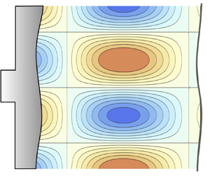
Figure 2. Sketch of the shape-modulated piston driving a rippled shock.
Let us now consider a corrugated piston in the form  $\psi _p(y)=\psi _{p0} \cos (k y)$, where $k=2 {\rm \pi}/\lambda$ is the perturbation wavenumber and $\psi _{p0}$ is the perturbation amplitude. Under the linear theory, the small parameter $\epsilon =\psi _{p0}k\ll 1$ determines the order of magnitude of the perturbations at the shock front and those in the compressed gas. Then, the shock perturbation amplitude can be defined as $\psi _s(t,y)= \psi _s(t)\cos (k y)$, where $\psi _s(t)$ measures the deviation from planarity of the shock front. Similarly, the streamwise and transverse velocity components in the post-shock gas reference frame, the post-shock pressure and density are expanded to first order in $\epsilon$ as
 $$\begin{gather} u(x,y,t)=\epsilon c_2 \bar{u}(x,t)\cos(k y), \end{gather}$$
 $$\begin{gather}v(x,y,t)=\epsilon c_2 \bar{v}(x,t)\sin(k y), \end{gather}$$
 $$\begin{gather}p(x,y,t)=p_2+\epsilon \rho_2 c_2^2 \bar{p}(x,t)\cos(k y), \end{gather}$$
 $$\begin{gather}\rho(x,y,t) =\rho_2+\epsilon \rho_2\bar{\rho}(x,t)\cos(k y), \end{gather}$$
respectively, with  $\bar {u}$, $\bar {v}$, $\bar {p}$ and $\bar {\rho }$ representing the dimensionless order-of-unity fluctuations. Variables are evaluated in the reference frame moving with the post-shock gas $x=x_l - U_p t$.
The linearised Euler conservation equations of mass, streamwise momentum, transverse momentum and energy read as
 $$\begin{gather} \frac{\partial \bar{\rho}}{\partial \tau} +\frac{\partial \bar{u}}{\partial \bar{x}}+\bar{v}=0, \end{gather}$$
 $$\begin{gather}\frac{\partial \bar{u}}{\partial \tau} +\frac{\partial \bar{p}}{\partial \bar{x}}=0, \end{gather}$$
 $$\begin{gather}\frac{\partial \bar{v}}{\partial \tau} -\bar{p}=0, \end{gather}$$
 $$\begin{gather}\frac{\partial \bar{p}}{\partial \tau} = \frac{\partial \bar{\rho}}{\partial \tau}. \end{gather}$$
In this notation, the space and time coordinates have been non-dimensionalised with the perturbation wavenumber and the post-shock speed of sound to give
 \begin{equation} \bar{x}=k x,\quad \bar{y}=k y,\quad \tau=k c_2 t, \end{equation}
so that the linear Euler equations become parameter free. The continuity, momentum conservation and energy conservation equations can be combined into a single, two-dimensional periodically symmetric wave equation for the post-shock pressure fluctuations, namely
 \begin{equation} \frac{\partial^2 \bar{p}}{\partial \tau^2}= \frac{\partial^2 \bar{p}}{\partial \bar{x}^2}-\bar{p}. \end{equation}
Equation (2.5), also known as the Klein–Gordon/telegraphist equation, is integrated for  $\tau \geq 0$ within the spatiotemporal domain bounded by the piston surface, $\bar {x}= 0$, and the shock front moving to the right $\bar {x}= {\mathcal {M}}_2\tau$, as depicted in figure 2.
The boundary conditions at the shock front are obtained from the linearised RH jump equations that read as
 $$\begin{gather} \frac{{\rm d} \xi_s}{{\rm d} \tau} = \frac{ {\mathcal{R}} \left(1+h\right)}{2 {\mathcal{M}}_2 \left({\mathcal{R}}-1\right)}\bar{p}_s , \end{gather}$$
 $$\begin{gather}\bar{u}_s =\frac{1-h}{2 {\mathcal{M}}_2}\bar{p}_s, \end{gather}$$
 $$\begin{gather}\bar{v}_s = {\mathcal{M}}_2 \left({\mathcal{R}}-1\right)\xi_s, \end{gather}$$
 $$\begin{gather}\bar{\rho}_s ={-}\frac{h}{{\mathcal{M}}_2^2}\bar{p}_s, \end{gather}$$
where  $h$ is the DK parameter defined in (1.1). In (2.6) $\xi _s = k\psi _s/\epsilon$ is the order-of-unity dimensionless shock displacement, whereas $\bar {p}_s$, $\bar {\rho }_s$, $\bar {u}_s$ and $\bar {v}_s$ are, respectively, the dimensionless fluctuations of pressure, density, streamwise velocity and transverse velocity immediately downstream of the shock front. The corresponding boundary condition at the piston surface is simply given by $\bar {u}(x=0,t)=0$. Note that two other canonical boundary conditions associated with the free surface and the isolated shock cases could be easily adopted. The former is simply given by considering $\bar {p}(x=0,t)=0$, as there is no force exerted on the free surface. The latter, on the other hand, changes the integration domain bounded by the leading reflected sonic wave travelling downstream, $\bar {x}= -\tau$, and the shock $\bar {x}= {\mathcal {M}}_2\tau$, where the isolated shock assumption reduces to neglecting the effect of the acoustic waves reaching the shock front from behind.
To solve the initial value problem described above for any EoS, three different methods will be employed. First, we numerically integrate the post-shock flow using the method of characteristics with the moving boundary condition at the shock. Second, an analytical approach is used, involving the transformation of the differential equations into algebraic equations in the Laplace variable space. The goal is to obtain the temporal evolution through the corresponding inverse Laplace transform, as demonstrated by Wouchuk & Cavada (Reference Wouchuk and Cavada2004). In addition, a linear stability analysis is conducted by expanding the self-similar solution associated with the one-dimensional perturbations to a planar shock case. This approach is particularly useful for determining shock stability when  $h>1$.
3. Numerical resolution by the method of characteristics
The linearised Euler equations in (2.3) can be rewritten in characteristic form as follows:
 $$\begin{gather} \frac{\partial \bar{j}^+}{\partial \tau} +\frac{\partial \bar{j}^+}{\partial \bar{x}}={-}\bar{m}, \end{gather}$$
 $$\begin{gather}\frac{\partial \bar{j}^-}{\partial \tau} -\frac{\partial \bar{j}^-}{\partial \bar{x}}={-}\bar{m}, \end{gather}$$
 $$\begin{gather}\frac{\partial \bar{m}}{\partial \tau} =\frac{ \bar{j}^{+}- \bar{j}^-}{2}, \end{gather}$$
where  $\bar {j}^{\pm }=\bar {u}\pm \bar {p}$ correspond to the Riemann invariants and $\bar {m}=(\partial v)/(\partial \bar {y})(\varepsilon c_2)^{-1}$ measures the transverse derivative of the lateral velocity perturbation. In (3.1a)–(3.1c), we have made use of the periodic symmetry of the flow when writing $\bar {m}$, since $v=\varepsilon c_2\bar {v}(\bar {x},\tau ) \sin (\bar {y})$. Similarly, the right-hand side in (3.1c) that includes the transverse pressure derivative yields $\bar {p}=(\bar {j}^+ - \bar {j}^-)/2$. It is worth noting that unlike one-dimensional flow, the values of $\bar {j}^+$ and $\bar {j}^-$ cannot be considered invariant functions due to the presence of transverse velocity perturbations $\bar {m}$ in the flow. The first two equations dictate that the functions $j^\pm$ evolve along the trajectories $\bar {x}\pm \tau =\textrm {constant}$, proportionally to the lateral velocity function $\bar {m}$, which also evolves by the corresponding transverse pressure gradient along the trajectory $\bar {x}=0$. The aftermath is that pressure perturbations can decay as they move away from the shock, in contrast to the one-dimensional case.
The integration of (3.1a)–(3.1c), which must be initiated with the conditions  $j^+_0=j^-_0=0$ and $\bar {m}_0={\mathcal {M}}_2({\mathcal {R}}-1)$ at $\tau =0$, calls for the corresponding boundary conditions, which take the form
 \begin{equation} \bar{j}^-=- \bar{j}^+ \end{equation}
at the piston  $\bar {x}=0$ and
 $$\begin{gather} \bar{j}^-=\mathscr{R}_s \bar{j}^+, \end{gather}$$
 $$\begin{gather}\frac{{\rm d}\bar{m}}{{\rm d} \tau} = \mathscr{T}_s (\bar{j}^+-\bar{j}^-) \end{gather}$$
at the shock front evaluated along the trajectory  $\bar {x}={\mathcal {M}}_2\tau$. The coefficients read as
 \begin{equation} \mathscr{R}_s = \frac{1- (1-h)/(2 {\mathcal{M}}_2)}{1+(1-h)/( 2{\mathcal{M}}_2)} \quad \text{and}\quad \mathscr{T}_s= {\mathcal{R}}\frac{1+h}{4}, \end{equation}
with the former standing for the reflection coefficient for an acoustic wave normally incident on the shock front from behind. This reflection coefficient has also been studied in the field of magnetohydrodynamics (MHD) by Rutkevich & Mond (Reference Rutkevich and Mond1992) in § 5. For  $h=1$, we have $\mathscr {R}_s=1$. If $1< h<1+2{\mathcal {M}}_2$, we have $\mathscr {R}_s>1$, so acoustic waves are amplified upon reflection from the shock front, indicating instability for planar geometry, in agreement with Fowles & Swan (Reference Fowles and Swan1973) and Kuznetsov (Reference Kuznetsov1984).
The consideration of a free surface modifies the boundary condition in (3.2), where the equation must be simply changed to  $\bar {j}^-= \bar {j}^+$ along the $\bar {x}=0$ trajectory. For the isolated shock case, the equation reduces to $j^+=0$ along the trajectory $\bar {x}=-\tau$. A sketch of the integration domain and the characteristics trajectories is offered in figure 3, where the absence of a supporting mechanism in the isolated shock case translates into omitting the effect of the reflected waves moving along the trajectory $\bar {x}-\tau =\textrm {constant}$.

Figure 3. Sketch of the modulated piston driving a rippled shock.
Direct numerical integration of the characteristic equations provides the results displayed in figure 4 for the particular case of  ${\mathcal {R}}=3$ and ${\mathcal {M}}_2=1/2$ (that renders $h_c=0$), and for different values of $h$ corresponding to the following cases: $h=-0.25$ (figure 4a,b), $h=0$ (figure 4c,d), $h=0.25$ (figure 4e, f), $h=0.75$ (figure 4g,h), $h=1.25$ (figure 4i,j) and $h=1.75$ (figure 4k,l). Both pressure disturbances at the shock $\bar {p}_s(\tau )=\bar {p}(\bar {x}={\mathcal {M}}_2\tau,\tau )$ (panels on the left) and at the piston $\bar {p}_p(\tau )=\bar {p}(\bar {x}=0,\tau )$ (panels on the right) are computed.

Figure 4. Numerical solution of the pressure evolution at the shock front  $\bar {p}_s(\tau )$ and at the piston surface $\bar {p}_p(\tau )$ for ${\mathcal {R}}=3$ and ${\mathcal {M}}_2=1/2$. The DK parameter in each panel is (a,b) $h=-0.25$, (c,d) $h=0$, (e, f) $h=0.25$, (g,h) $h=0.75$, (i,j) $h=1.25$ and (k,l) $h=1.75$.
Two primary conclusions can be drawn from the computations presented in figure 4. First, the shock dynamics can involve more than one frequency, depending on the value of  $h$. Second, the condition $h>h_c$ does not necessarily result in the growth of perturbations, even in cases where $h>1$. Note also that the slope of the pressure perturbations at $\tau \rightarrow 0$ grows with $h$ in figure 4(a–j). On the other hand, the initial slope turns positive for the largest $h$ considered, see figure 4(k,l). This can be theoretically anticipated with use made of (2.3) and (2.6) evaluated at the instant $\tau =0^+$ to give
 \begin{equation} b_0=\left.\frac{{\rm d}\bar{p}_s(\tau)}{{\rm d}\tau}\right|_{\tau=0}=\left.\frac{{\rm d}\bar{p}_p(\tau)}{{\rm d}\tau}\right|_{\tau=0} =\frac{2 {\mathcal{M}}_2^3 ({\mathcal{R}} - 1)}{h - 1 - 2 {\mathcal{M}}_2^2}, \end{equation}
which diverges for
 \begin{equation} h=h_m= 1 + 2 {\mathcal{M}}_2^2, \end{equation}
corresponding to  $h=1.5$ for ${\mathcal {M}}_2=1/2$. Note that this value is smaller than the limit $h=1 + 2 {\mathcal {M}}_2$, one of the values that indicates an absolutely unstable range $h>1+2{\mathcal {M}}_2$, the other is $h<-1$, for which the exponential growth of shock-front perturbations is associated with conditions that render multivalued (Erpenbeck Reference Erpenbeck1962; Kuznetsov Reference Kuznetsov1984) or multiwave (Kuznetsov Reference Kuznetsov1989; Menikoff & Plohr Reference Menikoff and Plohr1989) solutions of the planar Riemann/piston problem. The outcome of the numerical computations is a result of the acoustic reverberation and the two-dimensional character of the perturbation field. A more comprehensive explanation of the shock behaviour is presented in the following, with the assistance of corresponding theoretical analysis.
4. Resolution via the Laplace transform
To gain a deeper understanding of the initial value problem, we can utilise the Laplace transform method, similar to the approach taken by Wouchuk & Cavada (Reference Wouchuk and Cavada2004). Manipulation of the linearised RH equations leads to the following system of equations for the shock boundary conditions:
 \begin{equation} \dfrac{{\rm d}\xi_s}{{\rm d}\tau} =\sigma_a\bar{p}_s \end{equation}
and
 \begin{equation} \left(\sigma_b +{\mathcal{M}}_2 \right)\frac{\partial \bar{p}_s }{\partial \tau} +\left.\left(\sigma_b {\mathcal{M}}_2+ 1\right)\frac{\partial \bar{p}}{\partial x}\right|_{ x={\mathcal{M}}_2 \tau}={-}{\mathcal{M}}_2^2 \left({\mathcal{R}}- 1\right)\xi_s, \end{equation}
to be employed when integrating the Euler equations in the compressed gas. The factors accompanying the pressure perturbation in (4.1) and (4.2) are conveniently expressed in terms of the parameters
 \begin{equation} \sigma_a = \dfrac{{\mathcal{R}}}{{\mathcal{R}}-1}\dfrac{1+h}{2{\mathcal{M}}_2} \quad\text{and}\quad \sigma_b = \dfrac{1-h}{2{\mathcal{M}}_2}. \end{equation}
Following the same mathematical treatment as employed originally by Zaidel’ (Reference Zaidel’1960), the following hyperbolic transformation
 \begin{equation} x = r \sinh \chi, \quad \tau = r \cosh \chi \end{equation}
is employed, which serves to stretch out the integration domain in the origin, thereby transforming the initial value problem into a boundary value problem. The linearised RH equations are rewritten as
 $$\begin{gather} \dfrac{{\rm d}\xi_s}{{\rm d}r} =\dfrac{\sigma_a}{\sqrt{1-{\mathcal{M}}_2^2}}\hat{p}_s, \end{gather}$$
 $$\begin{gather}\hat{l}_s={-}\sigma_b \frac{\partial \bar{p}_s}{\partial r}+\sigma_d\xi_s \end{gather}$$
in these new coordinates  $r,\chi$, with the auxiliary function
 \begin{equation} \hat{l}_s=\dfrac{1}{r}\left.\frac{\partial \bar{p}}{\partial \chi}\right|_{ \chi_s} \end{equation}
that accounts for the pressure gradient being evaluated at the shock front. The initial tangential velocity created behind the shock at  $\tau =0$ is measured with the auxiliary function
 \begin{equation} \sigma_d ={-} \dfrac{{\mathcal{M}}_2^2 ({\mathcal{R}} - 1)}{\sqrt{1-{\mathcal{M}}_2^2}}. \end{equation}
Applying (4.4a,b) to the sound wave (2.5) gives
 \begin{equation} r\frac{\partial^2 \bar{p}}{\partial r^2} + \frac{\partial \bar{p}}{\partial r} + r \bar{p} = \frac{\partial \bar{l}}{\partial \chi}. \end{equation}
 The analysis continues by applying the Laplace transform on the functions  $\hat {p}$ and $\hat {l}$, which renders
 \begin{equation} \varPi = \int_0^\infty \bar{p}(r,\chi)e^{{-}s r}\,{\rm d}r \quad \text{and} \quad \varLambda = \int_0^\infty \bar{l}(r,\chi)e^{{-}s r}\,{\rm d}r, \end{equation}
respectively. Then, the sound wave equation (4.8) and the function  $\hat {l}(r,\chi )$ (not evaluated at the shock) can be written in terms of the variables $s=\sinh q$ and $\chi$, namely
 $$\begin{gather} \dfrac{\partial }{\partial q}\left(\cosh q\, \varPi\right)+\dfrac{\partial \varLambda}{\partial \chi}=0, \end{gather}$$
 $$\begin{gather}\dfrac{\partial }{\partial \chi}\left(\cosh q\, \varPi\right)+\dfrac{\partial \varLambda}{\partial q}=0. \end{gather}$$
After some straight algebra, the above system of equations can be integrated to provide
 $$\begin{gather} \varPi(\chi,q)=\dfrac{F_-(q-\chi)+F_+(q+\chi)}{\cosh q}, \end{gather}$$
 $$\begin{gather}\varLambda(\chi,q)=F_-(q-\chi)-F_+(q+\chi), \end{gather}$$
where the function  $F_-$ represents the sound perturbations radiated by the shock backwards into the compressed gas and $F_+$ indicates the sonic waves impinging on the shock front from behind. The relationship between the functions $F_-$ and $F_+$ arises from the specific choice of boundary conditions. When a rigid piston pushes the shock wave at $x=0$, the condition $F_- - F_+ = 0$ holds. On the other hand, for a free surface at $x=0$, the condition $F_- + F_+ = 0$ applies. For isolated shock waves, the boundary condition reduces to $F_+=$constant, thereby being defined by the initial condition $F_+=0$ since $\bar {p}(\tau =0)=0$.
In the Laplace variable  $q$, the boundary condition at the shock takes the form
 \begin{equation} \sinh q \varLambda_s(q) + (\sigma_b \sinh^2 q+ \sigma_c)\varPi_s(q)=\sigma_d, \end{equation}
where the parameter  $\sigma _c = \sigma _a{\mathcal {M}}_2^2({\mathcal {R}}-1)/(1-{\mathcal {M}}_2^2)$ has been introduced for convenience.
A simple form to obtain the evolution of the pressure field at the shock, and the associated shock ripple, is to exploit the solution of the sound wave equation. In particular, separation of variables yields Bessel functions as the family of solutions that satisfies (4.8), namely
 \begin{equation} \hat{p}(r,\chi)=\sum_{\nu=0}^{\infty}[A_{\nu}e^{\nu\chi}+B_{\nu}e^{-\nu\chi}] {\rm J}_{\nu}(r), \end{equation}
provided that Bessel functions of the second type must be excluded to avoid a divergent behaviour at the origin. At the shock, defining  $P_\nu =A_{\nu }e^{\nu \chi _s}+B_{\nu }e^{-\nu \chi _s}$, we have
 \begin{equation} \hat{p}_s(r,\chi)=\sum_{\nu=0}^{\infty}P_\nu {\rm J}_{\nu}(r), \end{equation}
where the coefficients  $P_\nu$ must be calculated with the aid of the boundary condition at the shock. The associated Laplace transform of (4.14) in the variable $q$, evaluated at the shock $\chi _s$, reads as
 \begin{equation} \varPi_s(q)=\sum_{\nu=0}^{\infty}P_{\nu} \frac{e^{-\nu q}}{\cosh q}, \end{equation}
where coefficients  $P_{\nu }$ can be expressed as a recurrence relationship using the Laplace transform $\varPi _s(q)$ obtained below, which requires knowledge of the corresponding boundary conditions behind the shock.
4.1. Isolated-shock boundary condition
To comprehend the effect of the piston on the evolution of the perturbed shock, it is convenient to examine first the shock evolution in the absence of the effects of the driving mechanism, i.e. the isolated shock boundary condition. For an isolated shock, the equation governing the pressure field at the shock can be expressed explicitly in terms of the Laplace variable  $s=\sinh q$ as follows:
 \begin{equation} \varPi_s(s) = \dfrac{\sigma_d}{s\sqrt{s^2+1}+\sigma_b s^2 + \sigma_c}, \end{equation}
provided that  $\varLambda _s(q)=\cosh q \varPi _s(q)$ holds when acoustic reverberations do not occur.
The values of the complex Laplace parameter  $s$ corresponding to the poles of the expression (4.16) denoted as $s^*=s_{R}^* + {\rm i}s_{I}^*$ in the complex plane are related by $\omega '=i s^* \surd {\smash [b]{(1-{\mathcal {M}}_2^2)}}kc_2$ to the solutions of $\omega '$ of the dispersion equation obtained through the normal-mode analysis (i.e. Fourier transform), see (90.10) in Landau & Lifshitz (Reference Landau and Lifshitz1987). The primed symbol $\omega '$, not present in Landau & Lifshitz (Reference Landau and Lifshitz1987) formulation, is used here to avoid confusion with the dimensionless $\omega$ function defined below.
The isolated case is useful to determine the shock fundamental frequencies, which are determined by the nature of the poles. In particular, the value of  $\sigma _b$ relative to $\sigma _c$ defines the distinguished limits. The acoustic nature of the post-shock field is responsible for the term $\sqrt {\smash [b]{s^2+1}}$ in (4.16), which introduces a branch cut in the complex plane of the Laplace variable $s$. As a direct consequence, not all purely imaginary poles that are roots of this equation are translated into undamped oscillations on the long time scale (Clavin & Searby Reference Clavin and Searby2016). The condition that sets the limits for stable oscillations is $s=\pm {\rm i}$, which occurs when $\sigma _b=\sigma _c$. This condition, which is equivalent as saying that $h=h_c$, reduces the dispersion relationship to $\sqrt {\smash [b]{s^2+1}}(s+\sigma _b \sqrt {\smash [b]{s^2+1}})=0$. The physical implication is that shock perturbations decay in the form $\tau ^{-1/2}$ (Fraley Reference Fraley1986), instead of the regular decay rate $\tau ^{-3/2}$ found for $h< h_c$ (or $\sigma _b>\sigma _c$). There exist, as noted in Bates (Reference Bates2004), Clavin & Searby (Reference Clavin and Searby2016) and Huete & Vera (Reference Huete and Vera2019), two distinguished scenarios for the regular decay case $\sigma _b>\sigma _c$: when $\sigma _b > \sigma _c+ 1/(4\sigma _c)$ (or $h< h_d$), the shock ripple undergoes a faster decay towards planarity than that occurring for $\sigma _c+ 1/(4\sigma _c)>\sigma _b>\sigma _c$, or $h_d< h< h_c$, where
 \begin{equation} h_d= \dfrac{-{\mathcal{R}}{\mathcal{M}}_2^2+(1-{\mathcal{M}}_2^2)^{3/2}\sqrt{1-{\mathcal{R}}^{{-}1}}}{1+{\mathcal{M}}_2^2\left({\mathcal{R}}-1\right)} \end{equation}
stands for DK parameter delimiting the highly damped oscillation regime  $h< h_d$, which corresponds to the limit presented in (12.1.28) in Clavin & Searby (Reference Clavin and Searby2016). It is important to note that while the long-time decay of the oscillations follows a $\tau ^{-3/2}$ pattern, the initial damping is primarily exponential.
A simpler form to picture the role of the poles in the stability analysis is offered in the sketch of figure 5. It depicts the poles in (4.16) by choosing the positive value  $s_{I}^*$ of the actual pair of conjugates that the dispersion relationship yields. In the regular decay regime $s_{R}^*=0$, while $s_{R}^*<0$ is only found for $h< h_d$. Regardless the case, for $h< h_c$ the amplitude of the oscillations decay with time but the frequency of the oscillation is constant, and its branch point given by $\sqrt {s^*\,^2+1}=0$ or $s^*=\pm {\rm i}$. It actually refers to the shock fundamental oscillation frequency, $s_0=1$ in the $r$ domain, or $\omega _0=\surd {\smash [b]{(1-{\mathcal {M}}_2^2)}}$ in the temporal domain measured in a reference frame moving with the shock front $\tanh \chi _s={\mathcal {M}}_2$. This frequency can be estimated by measuring the time required for an acoustic wave to travel a distance equal to one wavelength in the transverse direction. Since the sonic wave moves at velocity $c_2$ and the shock moves with velocity $D-U_p=u_2< c_2$, the distance needed to travel a $\lambda$ unit along the transverse direction is $c_2\Delta t$, while the shock moves frontwards a distance $v_s\Delta t$. We have $\lambda ^2 = (\Delta t)^2 (c_2^2-u_2^2)$ by construction, that finally renders $\lambda /(c_2 \Delta t)=\surd {\smash [b]{(1-{\mathcal {M}}_2^2)}}$.

Figure 5. Sketch of the poles in the complex plane  $s*=s_{R}+\pm {\rm i}s_{I}$.
Permanent oscillations at the shock front occur when  $h>h_c$ (or $\sigma _b<\sigma _c$), that is, when the imaginary poles in (4.16) lie outside the branch cut, i.e. $s_{I}^*>1$. It corresponds to the first non-decaying oscillating mode, whose frequency in the $r$-temporal domain is given by
 \begin{equation} s_{I}^*=s_1= \dfrac{1}{2}\left[\sqrt{q_1}+\dfrac{1}{\sqrt{q_1}}\right], \end{equation}
where
 \begin{equation} q_1=\dfrac{2\sigma_c-\sigma_b+\sqrt{1+4\sigma_c\left(\sigma_c-\sigma_b\right)}}{1+\sigma_b}, \end{equation}
as shown in Wouchuk & Cavada (Reference Wouchuk and Cavada2004) and Huete & Vera (Reference Huete and Vera2019). These two values, which tend to unity in the limit  $h\rightarrow h_c$, can be used to compute the first DK frequency in the $\tau$-temporal domain: $\omega _1= s_1\surd {\smash [b]{(1-{\mathcal {M}}_2^2)}}$. The dispersion relationship of the sound wave equation $\omega _{a1}^2=k_{a1}^2+1$ and the compatibility condition at the shock $\omega _1=\omega _{a1}-{\mathcal {M}}_2k_{a1}$ allow us to write
 \begin{equation} k_{a1}=\dfrac{\omega_1{\mathcal{M}}_2-\sqrt{\omega_1^2-1+{\mathcal{M}}_2^2}}{1-{\mathcal{M}}_2^2}\quad {\rm and} \quad \omega_{a1}=\dfrac{\omega_1-{\mathcal{M}}_2\sqrt{\omega_1^2-1+{\mathcal{M}}_2^2}}{1-{\mathcal{M}}_2^2} \end{equation}
for the longitudinal wavenumber and frequency of the acoustic perturbations in the shocked gas reference frame.
Understanding of the fundamental frequency is crucial as it appears even when there is a supporting mechanism such as a solid piston involved in the shock evolution. For instance, if  $\omega _1>1$, it implies that $k_{a1}<0$, which means that waves travel backwards in the compressed gas reference frame and could reach the potential piston. The reflected waves could then propagate back towards the shock, inducing additional frequencies. It is also convenient to define now the angle between the shock propagation direction $\hat {\boldsymbol{e}}_x$ and the acoustic wavevector $\hat {k}_{a}=(\cos \theta _{a1},\sin \theta _{a1})$, namely
 \begin{equation} \cos \theta_{a1}=\dfrac{\omega_1{\mathcal{M}}_2-\sqrt{\omega_1^2-1+{\mathcal{M}}_2^2}}{\omega_1-{\mathcal{M}}_2\sqrt{\omega_1^2-1+{\mathcal{M}}_2^2}}, \end{equation}
as depicted in figure 6. It is seen that the acoustic wave will move backwards when  $\cos \theta _{a1}<0$, i.e. when $\omega _1>1$, as deduced previously. Note that the angle of the shock fundamental frequency, given by substituting $\omega _1$ for $\omega _0$ in (4.21), is $\cos \theta _{a0}={\mathcal {M}}_2$, thereby indicating that the streamwise component of the sound wave velocity equals the shock velocity relative to the compressed gas, corresponding to evanescent emission as anticipated. The role of the acoustic angle with the shock–piston coupling is discussed in the following.

Figure 6. Sketch of the acoustic wave radiated from the shock and reflected from the piston with the DK frequency.
For completeness, the temporal evolution of the shock front is discussed in the following. One option to obtain it is by computing the pressure perturbations at the shock with the aid of the Bessel series. When (4.16) is rewritten in the variable  $q$, the following recurrence relationship for the coefficients $P_{\nu }$ in (4.15) is obtained:
 \begin{equation} P_\nu = \dfrac{2\sigma_b-\sigma_c}{1+\sigma_b}P_{\nu-2} +\dfrac{1-\sigma_b}{1+\sigma_b}P_{\nu-4}, \end{equation}
which is initiated with only two initial values:  $P_1=2/(1+\sigma _b)$ and $P_3=P_1+P_1^2(2\sigma _b-\sigma _c)$. Then, $P_\nu$ can be used in (4.14) to get $\bar {p}_s(\tau )$. However, Bessel series are not advisable for $\tau \gg 1$ when $h>h_c$, since they exhibit a very slow convergence. Alternatively, one may proceed by performing the inverse Laplace transform of (4.16), namely
 \begin{equation} \bar{p}_s(r)=\frac{1}{2{\rm \pi} \mathrm{i}}\int_{c-\mathrm{i}\infty}^{c+{\rm i}\infty}\varPi_s(s)e^{sr}\,{\rm d}s, \end{equation}
where  $c$ is a real number to the right of the singularities of $\varPi _s$ and $\mathrm {i}=\sqrt {-1}$ is the imaginary unit. The branch-point singularities $s=\pm \mathrm {i}$ represent the generation of evanescent sound wave perturbations that decay asymptotically in time in much the same way as Bessel functions. It finally renders
 \begin{equation}
\bar{p}_s(\tau) = \dfrac{2}{\rm \pi}\int_0^1{\rm
Im}\left[{\varPi_s(-{\rm i}z})\sin(z
\sqrt{1-{\mathcal{M}}_2^2}\tau)\right]\,{\rm d}z + {\rm
Residues}\left[\varPi_s(s)\right]
\end{equation}
\begin{equation}
\bar{p}_s(\tau) = \dfrac{2}{\rm \pi}\int_0^1{\rm
Im}\left[{\varPi_s(-{\rm i}z})\sin(z
\sqrt{1-{\mathcal{M}}_2^2}\tau)\right]\,{\rm d}z + {\rm
Residues}\left[\varPi_s(s)\right]
\end{equation}
that involves the evaluation of the poles in the complex plane. The second term on the right-hand side only appears for  $h>h_c$ and it corresponds to the non-decaying contribution associated with the imaginary poles placed outside of the branch cut, namely
 \begin{align} \lim_{s\rightarrow {\rm i} s_1}(s-{\rm i} s_1)\varPi_s^+(s)e^{s r}+\lim_{s\rightarrow -{\rm i} s_1}(s+{\rm i} s_1)\varPi_s^-(s) e^{{-}s r} =\bar{p}_s^{\infty}\sin(s_1 r)=\bar{p}_s^{\infty}\sin(\omega_1 \tau), \end{align}
where the superscript in  $\varPi _s^\pm$ denotes the sign of the root determination $\pm \sqrt {s^2+1}$ that depends on the position of the pole in the complex plane. The advantage of this method is that we can provide the long-time pressure perturbation amplitude in explicit form, namely
 \begin{equation} \bar{p}_s^{\infty}= \sigma_d\dfrac{ \sigma_b s_1^2-s_1\sqrt{s_1^2-1}-\sigma_c}{s_1\sqrt{1+4\sigma_c(\sigma_c-\sigma_b)}}, \end{equation}
which can be used, along with (4.5a), to get the associated asymptotic shock ripple amplitude.
4.2. The piston-driven shock front
When the shock boundary condition at  $\bar {x}=0$ (or $\chi =0$) is a driving piston, the final expression for the Laplace transform of the pressure at the shock corresponds to the functional equation
 \begin{equation} \varPi_s(q)=\alpha(q) + \beta(q)\varPi_s(q+2\chi_s), \end{equation}
whose explicit solution is still unknown. It dictates that the value of the pressure Laplace function at the shock depends on the value of the pressure Laplace function with a translation of  $+2\chi _s$ units in the frequency $q$ variable, demonstrating the Doppler shift effect between the shock and the reverberating surface. It is important to note that the majority of functional equations, even those that are linear, cannot be solved analytically. However, linear functional equations that are homogeneous and have continuous coefficients can often be solved analytically, such as in the case where $\alpha =\beta -1=0$, where (4.27) indicates that $\varPi _s(q)$ becomes periodic. In our current situation, the coefficients involved are complicated functions in the form of
 $$\begin{gather} \alpha(q)=\dfrac{\sigma_d}{\sinh(q+2\chi_s)}\dfrac{\sinh(q+2\chi_s)+\sinh q }{\sigma_b \sinh^2 q + \sigma_c+\cosh q \sinh q }, \end{gather}$$
 $$\begin{gather}\beta(q)=\dfrac{\sinh q}{\sinh(q+2\chi_s)}\dfrac{\cosh (q+2\chi_s) \sinh (q+2\chi_s) -\sigma_b \sinh^2 (q+2\chi_s) - \sigma_c}{\sigma_b \sinh^2 q + \sigma_c+\cosh q \sinh q }. \end{gather}$$
 Assuming that obtaining an analytical solution is not feasible, it may be possible to make some rearrangements to extract meaningful insights. For instance, if the functional equation allows for a translation in the independent frequency variable  $q\rightarrow q+ 2n\chi _s$, namely
 \begin{equation} \varPi_s(q+2n\chi_s)=\alpha(q+2n\chi_s) + \beta(q+2n\chi_s)\varPi_s[q+2(n+1)\chi_s]. \end{equation}
Equation (4.27) can be alternatively written as an iterative sequence to give
 \begin{align} \varPi_s(q)= \alpha(q) +\sum_{n=1}^\infty\alpha(q+2n\chi_s) \prod_{j=0}^{n-1}\beta(q+2j\chi_s) + \prod_{j=0}^{\infty}\beta(q+2j\chi_s)\lim_{q\rightarrow\infty}\dfrac{\alpha(q)}{1-\beta(q)}, \end{align}
that corresponds to a particular solution of (4.27). The limit in the last term on the right-hand-side actually corresponds to  $\varPi _s(q\gg 1)$, which is found to be zero, even if $\beta \rightarrow 1$, as occurs for $h\rightarrow 1-2{\mathcal {M}}_2^2$, since the function $\alpha (q)$ dominates the decay.
4.2.1. Asymptotic frequency analysis
By examining (4.30), it is easy to investigate whether there may be additional frequencies present in the shock front. The first DK shock oscillation frequency is that observed in isolated-shock conditions,  $q_1$. Any additional frequency must be also a pole (4.30), which translates into finding the zeros in $\sigma _b \sinh ^2 (q+2n\chi _s) + \sigma _c + \cosh (q+2n\chi _s) \sinh (q+2n\chi _s) =0$. The resulting solutions are as follows:
 \begin{equation} q_n = q_{n-1}\mathscr{D}_s^{{-}2} =q_{1}\mathscr{D}_s^{{-}2n}, \end{equation}
that includes the Doppler shift factor
 \begin{equation} \mathscr{D}_s =\dfrac{1+{\mathcal{M}}_2}{1-{\mathcal{M}}_2}>1. \end{equation}
Note that it lowers the value of the subsequent frequencies:  $q_n< q_{n-1}$. In the original Laplace variable, they read as
 \begin{equation} s_n= \dfrac{1}{2}\left[\sqrt{q_n}+\dfrac{1}{\sqrt{q_n}}\right]= \dfrac{1}{2}\left[\dfrac{\sqrt{q_1}}{\mathscr{D}_s^n}+\dfrac{\mathscr{D}_s^n}{\sqrt{q_1}}\right], \end{equation}
and, correspondingly,  $\omega _n= s_n\surd {\smash [b]{(1-{\mathcal {M}}_2^2)}}$ in the dimensionless temporal domain $\tau$. The corresponding values of the DK parameter $h$ at which the additional frequencies appear at the shock front correspond to those satisfying $s_n=1$:
 \begin{equation} \dfrac{\sqrt{q_1(h_{cn})}}{\mathscr{D}_s^{n}}+\dfrac{\mathscr{D}_s^{n}}{\sqrt{q_1(h_{cn})}}=2, \end{equation}
where  $q_1(h)$ is given by (4.19), provided that $\sigma _b$ and $\sigma _c$ are explicit functions of $h$. The first threshold $n=1$ corresponds to the SAE boundary $h_{c1}=h_c$.
The physical explanation for multifrequency shock behaviour is as follows. The piston receives constant-amplitude sonic radiation only when  $\cos \theta _{an}<0$. For the first mode, imposing $\cos \theta _{a1}<0$ is demanding the presence of left-travelling constant-amplitude sonic waves by the DK frequency $\omega _1$. However, the condition for an additional frequency $\omega _{n+1}$ to appear in the shock is harder to meet: the downstream radiated sound wave must be able to reach the shock after reflection from the piston wall, which requires $|\cos \theta _{an}|>{\mathcal {M}}_2$. This is readily seen with the aid of figure 6. Since wall reflection is symmetric, a left-travelling sound wave moving backwards at a velocity of $\boldsymbol {v}_{ax}/c_2=-{\mathcal {M}}_2\hat {\boldsymbol{e}}_x$ (streamwise projection) will reflect upwards with the same velocity projection and opposite sense. This sonic wave could then catch up to the shock from behind.
To illustrate the role of acoustic coupling, let us begin the analysis by gradually increasing the value of  $h$ from $h=h_c=h_{c_1}$, where the relationship between $\cos \theta _{a}$ and $s_1(h)$ determines the dependence on $h$. As stated, when $h\simeq h_c$ the shock radiates constant-amplitude sonic waves in the same manner as in isolated-shock conditions but with a different amplitude. The first distinguished case occurs at $h=h_{p1}$, above which the constant-amplitude sound waves radiated from the shock can reach the piston. This value is given by $\cos \theta _{a1}(h_{p1})=0$ associated with a purely transverse acoustic wave in the piston (or compressed gas) reference frame. At the piston position $\bar {x}=0$, the pressure perturbation function oscillates with lower frequency by the Doppler shift effect, as stated in the condition $\omega _{p1}=\omega _1/(1-{\mathcal {M}}_2\cos \theta _{a1})$. The second distinguished scenario arises when the second oscillation frequency appears at the shock, which occurs at $h=h_{c2}$. This condition is determined by $\cos \theta _{a_1}(h_{c2})=-{\mathcal {M}}_2$, where the wave reflected at the piston reaches the shock. The second oscillation frequency is also determined by the accumulated Doppler shift effect through
 \begin{equation} \omega_2 = \omega_1\dfrac{1+{\mathcal{M}}_2\cos\theta_{a1}}{1-{\mathcal{M}}_2\cos\theta_{a1}}, \end{equation}
which agrees with  $\omega _2=s_2\surd {\smash [b]{(1-{\mathcal {M}}_2^2)}}$ predicted previously by the poles of the Laplace transform in (4.33). The effect is repeated as $h$ increases. If the value of $h$ is high enough to result in high shock oscillation frequencies, the second oscillation frequency at the shock, $\omega _2$, can induce a secondary SAE that can reach the piston when $\cos \theta _{a2}(h_{p2})<0$. To evaluate this condition, (4.21) must be calculated using $\omega _2$. Likewise, the third shock oscillation mode occurs when $\cos \theta _{a2}(h_{c3})=-{\mathcal {M}}_2$, and so on. To prove right the validity of the previous analysis, figure 7 shows the value of the first four frequencies at the shock (solid lines) and at the piston (dashed), along with the fast Fourier transform (FFT) values obtained by the numerical integration in figure 4 (circles). Coloured regions identify the domain with one (blue), two (yellow), three (green) and four (red) frequencies at the shock. Grey circles refer to the FFT values given by the transient contribution, which corresponds to the shock/piston fundamental oscillation frequency. Note, however, that $h\rightarrow 1+2 {\mathcal {M}}_2$ will be associated with an infinite number of frequencies, a token of the change in the character of the solution towards an exponential growth. Note that this criterion, which is equivalent as evaluating the poles in (4.30), makes no use of $\alpha (q)$ nor $\beta (q)$ explicitly, thus being a proof of consistency.

Figure 7. Theoretical prediction of the pressure oscillation frequencies at the shock and at the piston surfaces. Numerical values are those associated with figure 4.
4.2.2. Transient evolution
We can use various methods to calculate the temporary changes in the perturbed shock from  $\tau =0$, as discussed previously in the context of the isolated-shock condition. On one side, we can make use of the Bessel series through (4.14). The corresponding $P_{\nu }$ values can be obtained with the help of (4.15), (4.27) and (4.28), and their values are shown in Appendix A. However, this method has a significant disadvantage: for $h>h_c$, the slow convergence of (4.15) makes it impractical to use for computing long-time shock evolution. Hence, the Bessel-series solution can only be used to calculate short-time transient evolution, as demonstrated below.
Although there is no explicit closed-form equation for  $\varPi _s(q)$, we can still obtain an expression for the transient response by performing an inverse Laplace transform of (4.24). This expression takes into account the decaying contribution associated with the shock fundamental frequency, as well as the potential residues related to frequencies such as $s_1$, $s_2$ and so on. Unlike the isolated-shock case, the function $\varPi _s(q)$ is not a closed expression, see (4.30). It is readily seen that neglecting the decaying contribution in the long time leads to
 \begin{align}
\bar{p}_s(\tau\gg1)&=\sum_{j=1}^n\left[\lim_{s\rightarrow {\rm
i} s_j}(s-{\rm i} s_j)\varPi_s^+(s)e^{s
r}+\lim_{s\rightarrow -{\rm i} s_j}(s+{\rm i}
s_j)\varPi_s^-(s) e^{s r} \right] \nonumber\\ &= \sum_{j=1}^n
\bar{p}_{j}^\infty \sin(\omega_j \tau) = \bar{p}_{1}^\infty
\sin(\omega_1 \tau) + \bar{p}_{2}^\infty \sin(\omega_2
\tau) + \cdots ,
\end{align}
\begin{align}
\bar{p}_s(\tau\gg1)&=\sum_{j=1}^n\left[\lim_{s\rightarrow {\rm
i} s_j}(s-{\rm i} s_j)\varPi_s^+(s)e^{s
r}+\lim_{s\rightarrow -{\rm i} s_j}(s+{\rm i}
s_j)\varPi_s^-(s) e^{s r} \right] \nonumber\\ &= \sum_{j=1}^n
\bar{p}_{j}^\infty \sin(\omega_j \tau) = \bar{p}_{1}^\infty
\sin(\omega_1 \tau) + \bar{p}_{2}^\infty \sin(\omega_2
\tau) + \cdots ,
\end{align}
which accounts the amplitudes and frequencies that may appear depending on the value of  $h$, as depicted in figure 7. For example, for $h_c< h< h_{c_2}$, the asymptotic solution takes the form of a single-oscillation harmonic, $\bar {p}_{1}^{\infty } \sin (\omega _1 \tau )$, much in the same way as the isolated shock, yet additional modes should be incorporated when $h$ is sufficiently high, as found in figure 7. Evaluating the residues of (4.27) yields the following expression for the long-time asymptotic amplitude of the first DK mode:
 \begin{align} \bar{p}_{1}^{\infty} &=\dfrac{\sigma_d}{\sqrt{1+4\sigma_c(\sigma_c-\sigma_b)}}\left\{\dfrac{1}{s_1}+\dfrac{1}{s_1\cosh\chi_s+\sqrt{s_1^2-1}\sinh\chi_s} \right.\nonumber\\ &\quad +\left[\sqrt{s_1^2-1}\cosh\chi_s+s_1 \sinh\chi_s-\sigma_b\left(s_1\cosh\chi_s+\sqrt{s_1^2-1}\sinh\chi_s\right)\right.\nonumber\\ &\quad +\left.\left.\sigma_c\left(s_1\cosh\chi_s+\sqrt{s_1^2-1}\sinh\chi_s\right)^{{-}1}\right]\varPi_s\left[q=\ln\left({\rm i} \left(s_1+\sqrt{s_1^2-1}\right)\right)+2\chi_s\right]\right\}, \end{align}
where the function  $\varPi _s$ can be evaluated from (4.30). Obtaining additional mode amplitudes $\bar {p}_{2}^{\infty }$, $\bar {p}_{3}^{\infty }$ and so on only demands additional relatively long algebra and objectively long expressions, so their final formulae are omitted for the sake of brevity. However, some numerical values are computed in figure 8 for the two first modes: $\bar {p}_{1}^{\infty }$ and $\bar {p}_{2}^{\infty }$. Two different cases have been chosen: the solid line corresponds to ${\mathcal {R}}=3$ and ${\mathcal {M}}_2=1/2$ (in agreement with figure 7), and the dot-dashed line corresponds to ${\mathcal {R}}=6$ and ${\mathcal {M}}_2=0.378$ (corresponding to the strong-shock limit values of air), although the parameter $h$ is used as a free parameter. Clearly, the use of a specific EoS will interrelate the three parameters ${\mathcal {R}}$, ${\mathcal {M}}_2$ and $h$. The two cases in figure 8 are purposely chosen to give $h_c=h_{c1}=0$ to facilitate the analysis.

Figure 8. Theoretical prediction of the first two asymptotic pressure oscillation amplitudes.
The thresholds for the second oscillation mode at the shock are  $h_{c2}=1.059$ (solid) and $h_{c2}=0.6$ (dot-dashed). The qualitative behaviour of the asymptotic amplitudes $\hat {p}_1^{\infty }$ and $\hat {p}_2^{\infty }$ is similar: they grow monotonically up to the vertical asymptote placed at $h=1+2{\mathcal {M}}_2$, corresponding to $h=2$ and $h=1.76$ for the solid and dot-dashed cases, respectively. Another noteworthy observation from figure 8 is that the asymptotic shock pressure amplitudes do not show any significant qualitative differences for $h$ values greater than or equal to $1-2{\mathcal {M}}_2^2$ or $h\geq 1$. The former is associated with the validity of (4.30), where the convergence of this expression may not be guaranteed. The second condition refers to the point at which one-dimensional perturbed planar shocks become unstable due to the cumulative effect of the acoustic shock–piston reverberations. This happens when the reflection coefficient at the shock (as indicated by the parameter $\mathscr {R}_s$ in (3.4a,b)) exceeds unity. A more detailed explanation is offered in the next section. Figure 8 also identifies, through the circle and triangle symbols, the conditions at which the complete temporal solution is given in figure 9.

Figure 9. Numerical values (solid black line), theoretical results via inverse Laplace transform (dashed orange line) and theoretical values through Bessel series (empty circles) of the shock pressure evolution for different shock conditions.
To complete the analysis based on the Laplace transform method, the evolution of the shock pressure perturbations is computed in figure 9 via Bessel series (empty circles) and the inverse Laplace transform (orange dashed lines), and compared with the numerical integration of the Euler equations (black solid lines). The computations are performed for the cases of greatest interest, specifically  $h>h_c$, as the stable solution in this regime is well established, see Zaidel’ (Reference Zaidel’1960) and Briscoe & Kovitz (Reference Briscoe and Kovitz1968). As a general observation, it can be concluded that the Bessel series method accurately predicts the short-to-medium time evolution of the shock, but its range of applicability decreases as the value of $h$ increases. This solution is restricted to the value of $\tau$ above which the solution does not converge. On the other hand, the inverse Laplace transform method provides a solution that agrees perfectly with the numerical solution for the entire time range considered. For the cases shown in figure 9(a–c), only one asymptotic amplitude/frequency remains in the long time, while two asymptotic amplitudes/frequencies are found for cases shown in figure 9(d–f), in perfect agreement with figures 7 and 8. Although not shown explicitly, numerical simulations for $h=-1$ have been also been carried out and contrasted with the theoretical predictions, and it was found that there is an initially linear growth followed by an accommodation region towards a constant-pressure perturbation at the shock. The shock ripple amplitude, as dictated by (2.6a), remains invariant regardless the shock pressure disturbances for $h=-1$. For the limiting case $h=1+2{\mathcal {M}}_2$, the solution exhibits singularity due to the divergence of both the fundamental shock oscillation frequency and the number of frequencies induced by reverberation. For values of $h$ beyond the indicated limits of $h<-1$ and $h>1+2{\mathcal {M}}_2$, represented by the shaded regions in figure 14, numerical calculations reveal that perturbations exhibit exponential growth in the long-time regime, consistent with Fourier analysis in the absence of a piston. However, the presence of the piston results in a retardation of the exponential growth, with linear growth observed up to $\tau$. Note that, in these ranges, as explained by Kuznetsov (Reference Kuznetsov1989), an unstable single-shock solution of the Riemann/piston problem evolves into a stable multiwave flow structure, making questionable the validity of linear analysis.
We have found, with both numerical and analytical methods, that the inclusion of the driving piston does not modify the character of the instability for  $h>h_c$. Moreover, the solution given by the particular solution of the functional equation (4.30) is in perfect agreement with the numerical solution in the whole DK neutrally unstable range, $h_c< h<1+2{ \mathcal {M}}_2$, thereby extending the stability condition beyond the limiting value $h=1-2{\mathcal {M}}_2^2$ studied in Wouchuk & Cavada (Reference Wouchuk and Cavada2004). This result contrasts with Bates (Reference Bates2015), where it was theoretically argued that small perturbations on the shock front are unstable for $h>h_c$ and $h<-1$. It is found that the initial value problem associated with the corrugated planar-geometry case is qualitatively different from that corresponding to cylindrical and spherical steady expanding shocks associated with the Noh problem, addressed in Huete et al. (Reference Huete, Velikovich, Martínez-Ruiz and Calvo-Rivera2021) and Calvo-Rivera et al. (Reference Calvo-Rivera, Huete and Velikovich2022). There it was found that the shock exhibits an unstable power-law evolution when $h>h_c$ and the perturbation mode number is sufficiently high. Although the planar piston-driven shocks and the expanding shocks of the Noh problem are similar in what concerns the steadiness of the shock, the flat profiles in the base-flow variables behind the shock and the acoustic coupling with the solid wall (planar), axis of symmetry (cylindrical) or centre (spherical), there exists a fundamental difference: the formulation of the piston-driven shock demands the inclusion of an external length, and the associated characteristic time.
Insightful information about the coupling effect between the shock and the piston can be obtained from the pressure field behind the shock, as observed in figure 10. Results have been computed with use made of the Bessel series because the analytical treatment is easier. In particular, the post-shock pressure field can be derived with the aid of (4.14) and undoing the hyperbolic variable change carried out in (4.4a,b), namely  $\chi = \tanh ^{-1}(\bar {x}/\tau )$ and $r = \sqrt {\tau ^2-\bar {x}^2}$, to give
 \begin{equation} \bar{p}(\bar{x},\tau)=\sum_{\nu=0}^{\infty}\dfrac{\left(\dfrac{\tau- \bar{x}}{\tau+ \bar{x}}\right)^{{\nu}/{2}}+\left(\dfrac{\tau- \bar{x}}{\tau+ \bar{x}}\right)^{-({\nu}/{2})}}{\left(\dfrac{1- {\mathcal{M}}_2}{1+ {\mathcal{M}}_2}\right)^{{\nu}/{2}}+\left(\dfrac{1- {\mathcal{M}}_2}{1+{\mathcal{M}}_2}\right)^{-({\nu}/{2})}}P_{\nu}{\rm J}_{\nu}(\sqrt{\tau^2-\bar{x}^2}) \end{equation}
for the piston-driven shock, and
 \begin{equation} \bar{p}(\bar{x},\tau)=\sum_{\nu=0}^{\infty}\left[\dfrac{(1+ {\mathcal{M}}_2)(\tau- \bar{x})}{(1- {\mathcal{M}}_2)(\tau+ \bar{x})}\right]^{-({\nu}/{2})}P_{\nu}{\rm J}_{\nu}(\sqrt{\tau^2-\bar{x}^2}) \end{equation}
for the isolated shock, where the coefficients for the former are given by (A9) in Appendix A, and those associated with the isolated case were presented in (4.22).

Figure 10. Pressure field in the compressed gas for  ${\mathcal {R}}=6$, ${\mathcal {M}}_2=0.378$ and $h=0.7$ ( $h>h_{c2}$) for two different boundary conditions corresponding to (a,c) piston-driven planar shock and (b,d) isolated shock. Panels (a,b) show the spatial pressure distribution at different times (solid lines) along with the shock pressure history (dashed lines).
The computations in figure 10, which have been also contrasted with the numerical integration of the Euler equations, have been done with  ${\mathcal {R}}=6$, ${\mathcal {M}}_2=0.378$ and $h=0.7$ ( $h>h_{c2}$) for two different boundary conditions corresponding to (a) a piston-driven planar shock and (b) an isolated shock. The upper plots show the spatial pressure distribution at different times (solid lines) together with the history of the pressure values at the shock along the spatial coordinate representing the shock position (dashed lines). The lower panels show the two-dimensional pressure field at $\tau =29$. It is found that the spatial frequency of the pressure field is much smaller than the frequency associated with the shock oscillations, as derived previously in (4.20a,b). Note that, unlike the case of the self-similar accretion shock discussed in Huete et al. (Reference Huete, Velikovich, Martínez-Ruiz and Calvo-Rivera2021) (see figure 11(a,c) there), the planar shock does not render a standing wave configuration downstream because the associated acoustic frequency $\omega _a$, see (4.20a,b), does not admit a null solution: $\omega _a>0$ for any value of the shock oscillation frequency.
4.2.3. The early-time behaviour
From the definition given in (3.4a,b), it is readily seen that when  $h>1$, the sonic reflection coefficient $\mathscr {R}_s$ exceeds 1. It implies that the amplitude of the sonic wave normally incident at the shock is reflected back with a greater amplitude. Since the piston reflection coefficient is unity, it may be tempting to assume that the positive feedback accumulation should lead to unstable behaviour of the shock front ripple and associated perturbation variables. This is actually true for one-dimensional planar shocks, i.e. independent of the transverse coordinate, perturbations of planar shocks (Fowles & Swan Reference Fowles and Swan1973; Swan & Fowles Reference Swan and Fowles1975; Kuznetsov Reference Kuznetsov1984), as well as for acoustic radial perturbations in spherically and cylindrically expanding steady accretion shocks (Huete et al. Reference Huete, Velikovich, Martínez-Ruiz and Calvo-Rivera2021). In the former case, the one-dimensional nature of perturbations implies normal incidence for all reflections of a reverberating sonic wave. In the latter case, the near-normal incidence is ensured by the scale-free geometry of the perturbation field. In Appendix B the conclusion made first by Fowles & Swan (Reference Fowles and Swan1973) (see their figures 3 and 4) that one-dimensional perturbed planar shocks are actually unstable for $h>1$ is confirmed both numerically and theoretically, the power-law growth is established and the corresponding power index is calculated.
For two-dimensional planar shocks, both Laplace-transform analysis and numerical integration of Euler equations predict no change in the character of the solution, implying the absence of unstable behaviour when  $h>1$. To illustrate the qualitative difference between perturbations in one and two dimensions, we utilise a Taylor expansion analysis that departs from the one-dimensional solution discussed previously by Fowles & Swan (Reference Fowles and Swan1973) and Kuznetsov (Reference Kuznetsov1984). This one-dimensional solution is a representative case when the shock–piston distance is much smaller than the perturbation wavelength. The Taylor expansion method accounts for deviations from the one-dimensional solution at later times that arise due to two-dimensional effects (as depicted in the sketch in figure 11).

Figure 11. Sketch of the quasi-one-dimensional acoustic flow in the early time shock–piston reflection.
We seek the perturbed pressure in the form
 \begin{equation} \bar{p}(\eta,\tau)= \tau^{\sigma}\sum_{j=0}^\infty \phi_j(\eta) \tau^{2j}= \tau^{\sigma}\phi_0(\eta)+\tau^{\sigma}\sum_{j=1}^\infty \phi_j(\eta) \tau^{2j}, \end{equation}
where  $\sigma$ is an eigenvalue to be determined. Such a form of solution, derived in Appendix B, stems from the fact that our perturbation problem is singular. In our small-amplitude approximation, we assume the shock-front ripple amplitude to be much smaller than all the characteristic lengths, including the shock–piston distance, but at $\tau \rightarrow 0$ the latter assumption is apparently violated. Further details can be found in §§ III.A and B of Velikovich (Reference Velikovich1996). It can be found there that the discrete spectrum of eigenvalues for a rigid piston is
 \begin{equation} \sigma = \begin{cases} 1 & \\ \dfrac{\ln \mathscr{R}_s}{\ln \mathscr{D}_s} + {\rm i}\dfrac{2 n {\rm \pi}}{\ln \mathscr{D}_s} , n=0,\pm 1, \pm 2,\ldots, \end{cases} \end{equation}
where  $\sigma =1$ corresponds to the solution addressed before through the Laplace transform. It is also the solution considered by all previous authors, starting from Roberts (Reference Roberts1945). This eigenvalue exists independently of the EoS and shock parameters. For the ideal gas EoS used by these authors, the solution (4.40) with $\sigma =1$ is the only one that is finite in the limit $\tau \rightarrow 0$, which is the heuristic reason why all the other eigenmodes could be discarded. The early-time behaviour of this eigenmode can be characterised by the expression ${\bar p}_s= b_0 \tau + O(\tau ^3)$, where $b_0$ is defined in (3.5). In addition, we have $\xi _s= 1 + O(\tau ^2)$, indicating that the shock front maintains the initial shape of the rippled piston up to terms on the order of $\tau \sim 1$.
The discrete spectrum of  $\sigma$ is given by the bottom-line expression in (4.41), which coincides with that obtained for the one-dimensional perturbed planar shock and presented in (B5a,b). It demonstrates that for $h>1$, implying $\mathscr {R}_s>1$, the real parts of all eigenvalues are positive, $\sigma _{R}>0$. Hence, the corresponding eigenmodes in (4.40) all vanish in the limit $\tau \rightarrow 0$. Since they are no longer singular, they cannot be discarded and must be included in our analysis. Unlike the one-dimensional planar case, which lacks proper scales, we utilise the previously defined dimensionless coordinates $\tau =kc_2 t$ and $\bar {x}=k x$ to construct the self-similar variable $\eta = \bar {x}/\tau$. Introducing this form of pressure perturbations into the sonic wave equation gives
 $$\begin{gather} \sigma(\sigma-1)\phi_0-2\eta(\sigma-1)\dfrac{{\rm d}\phi_0}{{\rm d}\eta}-(1-\eta^2)\dfrac{{\rm d}^2\phi_0}{{\rm d}\eta^2}\nonumber\\ +\displaystyle{\sum_{j=1}^\infty}\left[(2j+\sigma)(2j+\sigma-1)\phi_j-2\eta(2j+\sigma-1)\dfrac{{\rm d}\phi_j}{{\rm d}\eta}-(1-\eta^2)\dfrac{{\rm d}^2\phi_j}{{\rm d}\eta^2}+\phi_{j-1}\right]\tau^{2j}=0. \end{gather}$$
Likewise, the shock and piston boundary conditions can be expressed in terms of the eigenfunctions as
 \begin{align} &\left.\dfrac{1-h+2{\mathcal{M}}_2^2}{2{\mathcal{M}}_2}\sigma \phi_0({\mathcal{M}}_2)+(1-{\mathcal{M}}_2^2)\frac{{\rm d}\phi_0}{{\rm d} \eta}\right|_{\eta={\mathcal{M}}_2}\nonumber\\ &\quad +\sum_{j=1}^\infty\left\{\left[\dfrac{1-h+2{\mathcal{M}}_2^2}{2{\mathcal{M}}_2}(2j+\sigma) \phi_j({\mathcal{M}}_2)+\left.(1-{\mathcal{M}}_2^2)\frac{{\rm d}\phi_j}{{\rm d} \eta}\right|_{\eta={\mathcal{M}}_2}\right](2j+\sigma-1)\right.\nonumber\\ &\quad \left.+\dfrac{{\mathcal{M}}_2{\mathcal{R}}(1+h)}{2}\phi_{j-1}({\mathcal{M}}_2)\vphantom{\sum_{j=1}^\infty}\right\}\tau^{2j}=0 \end{align}
and  ${\rm d}\phi _j/({\rm d} \eta )|_{\eta =0}=0$, respectively. Note that the solution of $\phi _0(\eta )$ corresponds to the purely one-dimensional perturbations described by (B12), with the eigenvalue being determined by $\mathscr {D}_s^{\sigma }=\mathscr {R}_s$, where $\mathscr {R}_s$ denotes the shock reflection coefficient defined in (3.4a,b) and $\mathscr {D}_s$ is the Doppler shift factor provided in (4.32). It describes the effectively planar sonic reflections when the shock is very close to the piston $\tau \ll 1$ and two-dimensional effects have not yet entered into play. The other eigenfunctions corresponding to $j>1$ can be recursively determined by
 \begin{equation} (2j+\sigma)(2j+\sigma-1)\phi_j-2\eta(2j+\sigma-1)\dfrac{{\rm d}\phi_j}{{\rm d}\eta}-(1-\eta^2)\dfrac{{\rm d}^2\phi_j}{{\rm d}\eta^2}={-}\phi_{j-1} , \end{equation}
subject to
 \begin{gather} \left.\dfrac{1-h+2{\mathcal{M}}_2^2}{2{\mathcal{M}}_2}(2j+\sigma) \phi_j({\mathcal{M}}_2)+(1-{\mathcal{M}}_2^2)\frac{{\rm d}\phi_j}{{\rm d} \eta}\right|_{\eta={\mathcal{M}}_2} ={-}\dfrac{{\mathcal{M}}_2{\mathcal{R}}(1+h)}{2 (2j+\sigma-1)}\phi_{j-1}({\mathcal{M}}_2), \end{gather}
 \begin{gather} \dfrac{{\rm d}\phi_j}{{\rm d} \eta}\bigg|_{\eta=0}=0. \end{gather}
 Note that the inhomogeneous terms in (4.44) and (4.45), which involve the term  $\phi _{j-1}$ (or $\phi _0(\eta )$ for $j=1$), account for the multidimensional character of the problem. For example, the factor proportional to $\phi _{j-1}({\mathcal {M}}_2)$ in (4.45) comes from direct combination of the shock ripple perturbation (2.6a) and tangential velocity conservation across the shock (2.6c), while the term $\phi _{j-1}(\eta )$ in (4.44) comes from the $\partial ^2p/(\partial y^2)$ in the sound wave equation.
The solution of our linear problem is presented as an infinite sum of these eigenfunctions with constant coefficients. When  $\tau \ll 1$, i.e. when the distance of the shock from the piston is much smaller than the perturbation wavelength, the solution of this problem is the same as that for planar shock, where the eigenvalue $\sigma$ is determined by (B5a,b). Except for geometry factors, this is equivalent to the eigenvalue that characterises the cylindrical and spherical accretion shocks in the radial limit, see (3.3a) and (3.3b) in Huete et al. (Reference Huete, Velikovich, Martínez-Ruiz and Calvo-Rivera2021). However, in this case, the value of $\sigma$ is analytical, as opposed to the eigenfunction, which must be solved numerically for each mode number $n$ involved in $\sigma _{I}$. In the present case, the solution has been obtained iteratively by considering increasing values of $j$, starting from the one-dimensional solution for $j=0$ and using the given eigenmode $\sigma$. The numerical computation is rather demanding since the values of $\phi _j({\mathcal {M}}_2)$ must be calculated with high accuracy to capture the leading contributing terms for $\phi _j \tau ^{2 n}=O(1)$. For example, the solution of (4.44) and (4.45) is displayed in figure 12 for ${\mathcal {R}}=3$, ${\mathcal {M}}_2=1/2$ (which results in $h_c=0$) and $h=1.1$.


As a check of consistency, we can first evaluate the solution obtained by Taylor expansions with  $\sigma =1$ and compare it with a previously validated solution, such as that obtained using the Bessel series method. This comparison is displayed in figure 12(b), which shows the solution obtained for the same shock parameters: ${\mathcal {R}}=3$, ${\mathcal {M}}_2=1/2$ and $h=1.1$. The Taylor-expansion solution rendered by (4.40) (represented in solid line) is initiated with the eigenfunction $\phi _0=b_0$ that is consistent with the $\sigma =1$ solution for $\tau \rightarrow 0$. The solution via Bessel series (circles) is computed in a similar form as done in figure 9. We observe that there is a perfect agreement between the two methods, which validates the use of (4.40) for computing the shock dynamics even for $h>1$. However, the major advantage of this approach is that it allows the investigation of the full set of eigenvalues, including those that lead to unstable behaviour in purely one-dimensional configurations. For example, figure 12(a) displays the case $\sigma _{R}=0.1826>0$ that results from the same shock conditions as those in figure 12(b) but obtained from (4.41) (bottom-line expression). The solution, which has been computed for $n=\sigma _{I}=0$ and with an arbitrary constant $C_0=1$ in (B12), has demanded 270 figures of accuracy to get the $j_{max}=45$ term, which is enough to capture the evolution of the shock pressure up to $\tau \sim 20$. A longer time solution could not be shown due to numerical limitations. The impact of the two-dimensional effects is readily seen. While the one-dimensional solution exhibits a positive power-law growth, the introduction of two-dimensional terms leads to a function with non-increasing amplitude oscillations. However, since we are also interested in the late-time asymptotic of our solutions, a legitimate question is: Is the decay slower than the powers of time $-3/2$ and $-1/2$ predicted by the classics for moderate-strength and strong shocks, respectively, in ideal gases? Regardless the case, it is the non-decaying contribution associated with the eigenvalue $\sigma =1$ that would dominate in the long-time regime.
For the piston-driven two-dimensional corrugated shock, the early time and the long-time behaviour are unrelated because we can unequivocally define the regimes with the aid of the temporal scale  $1/(k c_2)$. On the other hand, scale-free perturbations follow the same power-law decay or growth throughout their evolution, from the early to the late time. This is true for one-dimensional perturbations in planar geometry, see Appendix B, and for all stable and unstable modes in spherical and cylindrical geometry (Huete et al. Reference Huete, Velikovich, Martínez-Ruiz and Calvo-Rivera2021). A heuristic argument can be made that their late-time asymptotics are the same as for the regular mode. It is based on the observation that each of the reverberation eigenmodes maintains a quasi-classical wave pattern, with a constant number of peaks and valleys between the shock and the piston, tracking the longitudinal mode number. The effective longitudinal wavelength increases as $t$, with the corresponding longitudinal wavenumber decreasing as $k_\parallel \sim 1/t$, whereas the transverse wavenumber $k_\perp =k$ remains constant. Hence, the reverberating sonic waves evolve to a grazing incidence, effectively decoupling the shock from the piston, irrespective of the value of the reflection coefficient $\mathscr {R}_s$ for normal incidence. The above explanation is consistent with the way the situation changes when the piston oscillates addressed in § 5: then the numbers of added peaks and values increase linearly with time, so $k_\parallel$ does not tend to zero, maintaining a finite angle of incidence of the reverberating sonic waves, leading to a non-resonant increase in the shock ripple amplitude with time.
We have commented previously that the particular case  $h=h_m=1+2 {\mathcal {M}}_2^2$ renders an infinite initial slope for the pressure evolution, as seen in (3.5). This stems from the fact that the sonic reflection coefficient for normal incidence $\mathscr {R}_s=\mathscr {D}_s$. In other words, the Doppler-shift weakening of a sonic wave in a single cycle of its reverberation between the shock and the piston, $1/\mathscr {D}_s$, is exactly compensated for by its amplification in the shock reflection, because $\mathscr {R}_s>1$. Then, in this case the eigenvalue becomes degenerate because both top line and bottom line of (4.41) yields the same value $\sigma =1$. Then, the corresponding time dependence for the shock ripple takes the form $\xi _s\sim \ln \tau$, which diverges for $\tau \rightarrow 0$.
5. Forced resonance in the SAE regime
It is found that the initial value problem associated with the corrugated planar-geometry case is qualitatively different from that corresponding to cylindrical and spherical steady expanding shocks associated with the Noh problem, addressed in Velikovich et al. (Reference Velikovich, Murakami, Taylor, Giuliani, Zalesak and Iwamoto2016), Huete et al. (Reference Huete, Velikovich, Martínez-Ruiz and Calvo-Rivera2021) and Calvo-Rivera et al. (Reference Calvo-Rivera, Huete and Velikovich2022). It was demonstrated there that the shock exhibits an unstable power-law evolution when  $h>h_c$ and the perturbation mode number is sufficiently high. The reason for this difference is that in the linear perturbation analysis for the steady expanding shock of the Noh problem, the solution takes the form of $t^\sigma$, where $\sigma$ is the eigenvalue. This solution is valid for the whole temporal domain due to the singular scale-free nature of the perturbed spherical or cylindrical flow. Because of the lack of scales, the pressure field behind the shock is made of a time-dependent standing wave, whose eigenfunction is determined as a function of the self-similar variable $r/(c_2 t)$. There was not any characteristic frequency involved in the acoustic field but rather an instantaneous frequency Im $\{\sigma \}/t>0$ that changed with time correspondingly with the self-similar character of the solution. As a direct outcome, the standing acoustic wave behind the shock resulted in an in-phase feedback between the shock and either the axis of symmetry (in cylindrical geometry) or the centre (in spherical geometry). The planar piston-driven shock problem addressed in this work does not render any in-phase acoustic coupling. As derived from the frequency analysis and supported by the numerical computations, the DK mode can only excite additional lower-frequency modes, thereby composing a multifrequency behaviour at the shock with finite amplitudes for each mode. However, it is worth noting that it is possible to create configurations where in-phase perturbations can appear, but only through external means. One example is the time-dependent wavy piston: an oscillating wall surface in the form $\psi _p(y,t) = \psi _{p0}\cos (k y) \cos (\varOmega _p t)$, which reduces to our previous configuration when the externally forced frequency $\varOmega _p\rightarrow 0$. The problem is similar except that the boundary condition at the piston is
 \begin{equation} \left.\dfrac{\partial \bar{p}}{\partial \bar{x}}\right|_{\bar{x}=0}=\omega_p^2\cos(\omega_p \tau), \end{equation}
where  $\omega _p=\varOmega _p/(k c_2)$ is the dimensionless piston oscillation frequency. Upon performing the same mathematical steps, it was discovered that the functional equation governing the Laplace transform of pressure switches from (4.27) to
 \begin{equation} \varPi_s(q)=\alpha(q) +\gamma(q)+ \beta(q)\varPi_s(q+2\chi_s), \end{equation}
where
 \begin{equation}
\gamma(q)={-}\omega_p^2\dfrac{\sinh^2(q+\chi_s)\sinh
q}{(\sinh q\cosh q +\sigma_b \sinh^2
q+\sigma_c)[\omega_p^2+\sinh^2(q+\chi_s)]}
\end{equation}
\begin{equation}
\gamma(q)={-}\omega_p^2\dfrac{\sinh^2(q+\chi_s)\sinh
q}{(\sinh q\cosh q +\sigma_b \sinh^2
q+\sigma_c)[\omega_p^2+\sinh^2(q+\chi_s)]}
\end{equation}
carries the oscillating piston effects. The particular solution of the functional equation (5.2) can be written as
 \begin{equation} \varPi_s(q)= \alpha(q)+\gamma(q) +\sum_{n=1}^\infty\left[\alpha(q+2n\chi_s)+\gamma(q+2n\chi_s)\right] \prod_{j=0}^{n-1}\beta(q+2j\chi_s) , \end{equation}
from which the residues can be analysed to infer the asymptotic long-time solution of the shock. It is proved convenient to rewrite (5.3) in the Laplace variable  $s$, namely
 \begin{equation}
\gamma(s)={-}\omega_p^2\dfrac{s(s+{\mathcal{M}}_2\sqrt{s^2+1})^2}{(s\sqrt{s^2+1}
+\sigma_b s^2
+\sigma_c)[\omega_p^2(1-{\mathcal{M}}_2^2)+(s+{\mathcal{M}}_2\sqrt{s^2+1})^2]},
\end{equation}
\begin{equation}
\gamma(s)={-}\omega_p^2\dfrac{s(s+{\mathcal{M}}_2\sqrt{s^2+1})^2}{(s\sqrt{s^2+1}
+\sigma_b s^2
+\sigma_c)[\omega_p^2(1-{\mathcal{M}}_2^2)+(s+{\mathcal{M}}_2\sqrt{s^2+1})^2]},
\end{equation}
whose first term in the denominator agrees with the denominator in (4.16), from which the poles associated with the self-induced oscillations for  $h>h_c$ can be withdrawn. The second term in the denominator only introduces an additional frequency to the shock oscillation, due to the oscillating wavy piston. By simple inspection we observe that, for the acoustic waves radiated by the piston to reach the shock, the oscillation frequency must be greater than $\omega _{p,{min}}=1/\surd {\smash [b]{(1-{\mathcal {M}}_2^2)}}$. When this occurs, the pole associated with the second term in the denominator is purely imaginary with amplitude greater than unity. Then, the two poles are placed outside of the branch cut sketched in figure 5 and contribute with a permanent oscillatory function. The frequency at the shock is given by the pair of imaginary poles $s=\pm {\rm i}s_p$, where
 \begin{equation} s_p=\dfrac{\omega_p-{\mathcal{M}}_2\sqrt{\omega_p^2-1}}{\sqrt{1-{\mathcal{M}}_2^2}}, \end{equation}
which stretches to  $s_p \surd {\smash [b]{(1-{\mathcal {M}}_2^2)}}$ in the temporal domain $\tau$. This is relevant because the externally induced frequency can trigger a linear instability at the shock when the self-induced frequency agrees with the externally induced frequency $s_p=s_1$, namely
 \begin{equation} \omega_{p_1}=\dfrac{\omega_1-{\mathcal{M}}_2\sqrt{\omega_1^2-(1-{\mathcal{M}}_2^2)}}{1-{\mathcal{M}}_2^2}. \end{equation}
The linear growth is readily explained by looking at the poles order. When  $s_p\neq s_1$ (or any other pole, if present), then the denominator takes the form $(s^2+s_p^2)(s^2+s_1^2)(s^2+s_2^2)\cdots,$ which translates into the sum of harmonic functions, as carried out before in (4.36). However, when $s_p= s_1$, the order of the imaginary pole of the resonant frequency increases $(s^2+s_p^2)^2(s^2+s_2^2)\cdots,$ thereby modifying the asymptotic solution. Upon direct inspection of the residues, the long-time pressure field in the resonance mode can be expressed as
 $$\begin{gather}
\bar{p}_s(\tau\gg1)=\lim_{s_j\rightarrow {\rm i}
s_p}\dfrac{{\rm d}}{{\rm d} s}\left[(s-{\rm i}
s_p)^2\varPi_s^+(s)e^{s r}\right]+\lim_{s\rightarrow -{\rm
i} s_p}\dfrac{{\rm d}}{{\rm d} s}\left[(s+{\rm i}
s_p)\varPi_s^-(s) e^{{-}s r}\right]\nonumber\\
+\sum_{j=2}^n\left[\lim_{s_j\rightarrow {\rm i} s_j}(s-{\rm
i} s_j)\varPi_s^+(s)e^{s r}+\lim_{s\rightarrow -{\rm i}
s_j}(s+{\rm i} s_j)\varPi_s^-(s) e^{s r}\right] \sim
g_{0}^\infty \tau \sin(\omega_1 \tau-{\rm \pi}/2),
\end{gather}$$
$$\begin{gather}
\bar{p}_s(\tau\gg1)=\lim_{s_j\rightarrow {\rm i}
s_p}\dfrac{{\rm d}}{{\rm d} s}\left[(s-{\rm i}
s_p)^2\varPi_s^+(s)e^{s r}\right]+\lim_{s\rightarrow -{\rm
i} s_p}\dfrac{{\rm d}}{{\rm d} s}\left[(s+{\rm i}
s_p)\varPi_s^-(s) e^{{-}s r}\right]\nonumber\\
+\sum_{j=2}^n\left[\lim_{s_j\rightarrow {\rm i} s_j}(s-{\rm
i} s_j)\varPi_s^+(s)e^{s r}+\lim_{s\rightarrow -{\rm i}
s_j}(s+{\rm i} s_j)\varPi_s^-(s) e^{s r}\right] \sim
g_{0}^\infty \tau \sin(\omega_1 \tau-{\rm \pi}/2),
\end{gather}$$
that involves a linear growth contribution that dominates when  $g_{0}^\infty \tau \gg 1$. After some straightforward but lengthy algebra, the growth rate coefficient can be analytically derived:
 \begin{align} g_0^\infty=\frac{\omega_{p_1}^4\sqrt{1-{\mathcal{M}}_2^2}}{2s_1\sqrt{1+4\sigma_c(\sigma_c-\sigma_b)}}\dfrac{s_1^2\sqrt{s_1^2-1}+\sigma_c-\sigma_b s_1^2 }{s_1^2(1-{\mathcal{M}}_2^2)-\omega_{p_1}^2(1+{\mathcal{M}}_2^2)+{\mathcal{M}}_2^2+2{\mathcal{M}}_2\sqrt{\smash[b]{\omega_{p_1}^2-1}}}, \end{align}
where  $\omega _{p_1}$ depends on $s_1$ (or $\omega _1$) according to (5.7). To verify this claim, two numerical simulations are conducted for the same perturbation-free conditions: ${\mathcal {R}}=6$, ${\mathcal {M}}_2=0.378$ and $h=0.75$, which provides the self-induced oscillation frequency $s_1=1.47416$. The first computation, displayed in figure 13(a), is carried out with an externally piston-exerted frequency $\omega _{p}=\omega _{p_1}=2.03453$, while the second case, shown figure 13(b), is computed with an arbitrary frequency $\omega _{p}=1.6\neq \omega _{p_1}$. The numerical simulation results indicate that only the non-resonant frequency provides a neutrally stable solution. Furthermore, the linear growth factor predicted analytically, $g_{0}^\infty =1.72813$ (orange dotted line), perfectly matches the numerical simulation results (black solid lines).

Figure 13. (a) Resonant and (b) non-resonant behaviour of the shock front when the piston oscillates with frequency  $\omega _p$. Shock conditions are ${\mathcal {R}}=6$, ${\mathcal {M}}_2=0.378$ and $h=0.75$.
Moreover, when more than one frequency are present in the shock because of the reverberations of the self-induced oscillations,  $h>h_{c_2}$, a linear growth could also exist. For that to happen, for the pole associated with the displaced term in (5.3), $\omega _{p_2}^2+\sinh ^2(q+3\chi _s)$ should provide a pole that agrees with $s_2$, thereby changing the order of the imaginary pair of poles. Because of the Doppler shift, this condition is harder to meet. For example, for the case computed in figure 13, $\omega _{p_2}=0.898<\omega _{p,{min}}$, associated with a low-frequency condition whose acoustic waves radiated from the piston cannot reach the shock. Alternatively, an external excitation can be incorporated via periodic disturbances placed ahead of the shock in the form of vorticity, entropy and/or sound as done in Wouchuk, Huete & Velikovich (Reference Wouchuk, Huete and Velikovich2009) and Huete, Velikovich & Wouchuk (Reference Huete, Velikovich and Wouchuk2011); Huete, Wouchuk & Velikovich (Reference Huete, Wouchuk and Velikovich2012), where the resonance possibility was not considered because the approaches were developed under the ideal gas assumption, i.e. $h< h_c$. In summary, a linear growth of the shock ripple amplitude in a two-dimensional planar shock can only occur for $h>h_c$ if an external in-phase perturbation field input is applied.
6. Conclusions
We have conducted an analysis of the stability of a planar shock that is driven by a weakly perturbed piston. The study was carried out utilising three independent methods: direct numerical integration of the Euler equations utilising the method of characteristics; theoretical analysis via the Laplace transform, which was executed through the Bessel series method in accordance with Zaidel’ (Reference Zaidel’1960) and Briscoe & Kovitz (Reference Briscoe and Kovitz1968) and the direct inverse Laplace transform in accordance with Wouchuk & Cavada (Reference Wouchuk and Cavada2004); and Taylor expansion that departs from the one-dimensional planar shock solution as in Velikovich (Reference Velikovich1996). The excellent agreement between the independent methods provides a means of cross-validation for the final results. The main conclusions are summarised as follows.
(i) The presence of a rigid piston driving the shock does not affect the limits nor the character of the instability against two-dimensional perturbations, when compared to the isolated shock case. For
$h< h_c$, the shock perturbation amplitude decays with the power law $t^{-3/2}$, for $h=h_c$ it decays with the power law $t^{-1/2}$, and for $h_c< h<1+2{\mathcal {M}}_2$, the shock dynamics exhibits a constant sustained oscillation. Another distinguished case occurs for $h< h_d$, where the initial damping of the perturbations is exponential, as observed by Bates (Reference Bates2004) and Clavin & Searby (Reference Clavin and Searby2016). The influence of the shock–piston interaction is manifested in the change of the amplitude of the oscillations and, more importantly, the possibility of exciting secondary frequencies that result from the acoustic waves reflected from the piston that can reach back the shock from behind. The conditions at which these secondary frequencies arise can be simply obtained by accounting for the two-dimensional character of the acoustic field and the Doppler effect associated with the moving shock. The asymptotic amplitudes that dominate in the long-time limit are analytically obtained by direct inspection of the residues of the Laplace transform.(ii) As the difference
$h-h_c>0$ grows, the number of secondary frequencies increases, and so does the amplitude associated with each oscillation mode. When $h$ approaches the limit $h\rightarrow 1+2{\mathcal {M}}_2$, the fundamental frequency associated with the DK mode diverges along with the corresponding amplitude. The influence of the piston in this issue is that for $h\rightarrow 1+2{\mathcal {M}}_2$ the number of secondary frequencies and their associated amplitude also diverge. This is a token of the change of the character of the solution, which is found to be an exponential instability for $h> 1+2{\mathcal {M}}_2$ and $h<-1$ (Erpenbeck Reference Erpenbeck1962; Huete & Vera Reference Huete and Vera2019), but that is ultimately associated with the splitting of a single unstable shock front into a sequence of stable simple waves (Kuznetsov Reference Kuznetsov1989; Menikoff & Plohr Reference Menikoff and Plohr1989). The influence of the piston in these unstable ranges is that, at early times, the growth rate is linear because of the constrainment effect of the solid wall.(iii) A true instability, as opposed to the neutral stability discussed above for
$h_c< h<1+2{\mathcal {M}}_2$, is possible in resonant conditions: when the shock is excited with a frequency that coincides with the self-induced oscillation frequency of the DK mode. The excitation can be placed in the upstream flow or in the driving mechanism and the qualitative result is the same: a linear growth of the shock perturbation amplitude $\sim t$. In this work, the excitation that has been placed in the driving mechanism by considering an oscillating wavy piston. Although this may be seen as a very particular case to trigger the shock instability, the outcome is actually important in conditions where the driving mechanism comes with a noisy source that involves a full spectrum of frequencies. In such case, the resonant frequency will dominate the shock dynamics in the long time.(iv) For
$h>1$, the character of the solution of the perturbed two-dimensional shock does not change, but it makes a difference for purely one-dimensional perturbations. Since sonic disturbances hit planarly on the shock surface and on the solid piston, and because there is no change of the incidence angle in subsequent reflections resulting from two-dimensional effects, when the reflection coefficient at the shock is greater than unity ($\mathscr {R}_s>1$) the acoustic reverberation translates into a power-law growth of the perturbations in the form $t^{\sigma _{R}}$, where $\sigma _{R}$ is given in (B5a,b). Likewise, perturbation will decay with a similar power law for any value of the DK parameter in the range $-1< h<1$.


For convenience, all the different regimes of shock perturbation evolution have been depicted in figure 14, they include isolated two-dimensional perturbed shock, piston-driven two-dimensional perturbed shock, oscillating-piston-driven two-dimensional perturbed shock, piston-driven one-dimensional perturbed shock and the spherical or cylindrical expanding accretion shock perturbed in two or three dimensions, with the latter corresponding to the results given in Huete et al. (Reference Huete, Velikovich, Martínez-Ruiz and Calvo-Rivera2021). Hatched regions correspond to conditions that render exponential instability and multiwave solutions of the planar Riemann/piston problem (Kuznetsov Reference Kuznetsov1989; Menikoff & Plohr Reference Menikoff and Plohr1989). It is readily observed that for the shock to be unstable, an in-phase perturbation feedback must occur between the shock and the supporting mechanism, as spontaneously occurs in expanding accretion shocks, whose perturbation field is scale free and externally exerted in the oscillating planar piston case.

Figure 14. Chart of the shock perturbation regimes associated with different steady shock configurations. Hatched regions correspond to conditions that render multiwave solutions of the planar Riemann/piston problem.
All the results presented in this work have been expressed in terms of properties associated with the EoS and the shock intensity. They are the shock compression ratio  ${\mathcal {R}}$, the post-shock Mach number ${\mathcal {M}}_2$ and the DK parameter $h$. Then, they are easily extrapolated to any shock conditions and any fluid EoS, in a same manner as done in Huete et al. (Reference Huete, Velikovich, Martínez-Ruiz and Calvo-Rivera2021) for expanding accretion shocks, where analytical expressions for ${\mathcal {R}}$, ${\mathcal {M}}_2$ and $h$ were derived explicitly for ideal gas EoS, a vdW gas and for simple metals described by a three-terms EoS. A ready example where the condition $h>h_c$ is met is the finite-strength shock moving in a vdW gas with low adiabatic index, see Bates & Montgomery (Reference Bates and Montgomery2000) and Huete et al. (Reference Huete, Velikovich, Martínez-Ruiz and Calvo-Rivera2021).
In the light of the results of Clavin (Reference Clavin2013), Lodato et al. (Reference Lodato, Vervisch and Clavin2016) and Shen et al. (Reference Shen, Pullin, Samtaney and Wheatley2021), which suggest that the formation of triple points and Mach stems in the shock front occurs at  $\tau \sim \varepsilon ^{-1}$ even in ideal gases, further measures can be taken to complete the stability analysis by including weakly nonlinear disturbances. They include the formulation of a theoretical framework that incorporates arbitrary equations of state. In addition, other boundary conditions representing distinguished supporting mechanism may have a significant influence in the triple-point formation.
Acknowledgements
The authors wish to thank Professor J.G. Wouchuk and Dr J.W. Bates for carefully reading the manuscript and for their valuable comments and Professor D. Martínez-Ruiz for his assistance in the numerical analysis.
Funding
The work of A.C.R and C.H. has been supported with project TED2021-129446B-C41 (MICINN/FEDER, UE). The work of C.H. has also received support from the Madrid Government (Comunidad de Madrid-Spain) under the Multiannual Agreement with UC3M (H2SAFE-CM-UC3M). The work of A.L.V. has been supported by the National Nuclear Security Administration of the US Department of Energy.
Declaration of interests
The authors report no conflict of interest.
Appendix A. Bessel-series coefficients
We can follow Briscoe & Kovitz (Reference Briscoe and Kovitz1968) to obtain an analytical solution in the form of Bessel series (4.14), with the aid of (4.15), (4.27) and (4.28) to give
 \begin{align} &\sum_{\nu=0}^{\infty} P_\nu e^{-\nu q}(a_{4,\nu} e^{4 q}+a_{2,\nu} e^{2 q}+a_{0,\nu} +a_{{-}2,\nu} e^{{-}2 q}+a_{{-}4,\nu} e^{{-}4 q})\nonumber\\ &\quad = b_3 e^{3q} + b_1 e^{q} + b_{{-}1} e^{{-}q} +b_{{-}3} +e^{{-}3q}, \end{align}
where the accompanying coefficients read as
 $$\begin{gather} a_{4,\nu}= e^{{-}4\chi_s}[(\sigma_b -1) + (\sigma_b +1) e^{2 \nu \chi_s} ], \end{gather}$$
 $$\begin{gather}a_{2,\nu} = 2(2\sigma_c-\sigma_b)(e^{{-}4\chi_s}+e^{2 \nu \chi_s}), \end{gather}$$
 $$\begin{gather}a_{0,\nu} = e^{{-}4\chi_s}[ \sigma_b +1 -( \sigma_b-1)e^{8\chi_s}]( 1-e^{2 \nu\chi_s}), \end{gather}$$
 $$\begin{gather}a_{{-}2,\nu} ={-}2(2\sigma_c-\sigma_b)(e^{4\chi_s}+e^{2 \nu \chi_s}), \end{gather}$$
 $$\begin{gather}a_{{-}4,\nu} ={-}e^{4\chi_s}[ ( \sigma_b +1) +( \sigma_b -1) e^{2 \nu \chi_s}] \end{gather}$$
for the  $\nu$-dependent functions and
 $$\begin{gather} b_{3} ={-}2\frac{\sigma_c}{\sigma_a} e^{{-}2\chi_s}(1+e^{{-}2\chi_s}), \quad b_{1} ={-}2\frac{\sigma_c}{\sigma_a} e^{2\chi_s}(1+e^{{-}6\chi_s}), \end{gather}$$
 $$\begin{gather}b_{{-}1} = 2\frac{\sigma_c}{\sigma_a} e^{{-}2\chi_s}(1+e^{6\chi_s}), \quad b_{{-}3} = 2\frac{\sigma_c}{\sigma_a} e^{2\chi_s}(1+e^{2\chi_s}) \end{gather}$$
for the inhomogeneous part, respectively. For  $\nu \geq 9$, it is straightforward to write the following recurrence relationship for the coefficients
 \begin{equation} P_\nu ={-} \frac{a_{2,\nu-2}}{a_{4,\nu}}P_{\nu-2} - \frac{a_{0,\nu-4}}{a_{4,\nu}}P_{\nu-4} - \frac{a_{{-}2,\nu-6}}{a_{4,\nu}}P_{\nu-6} - \frac{a_{{-}4,\nu-8}}{a_{4,\nu}}P_{\nu-8} \end{equation}
that can be initiated with the first four odd coefficients
 \begin{equation} \left. \begin{aligned} P_1 & = \frac{b_3}{a_{4,1}}, \quad P_3 = \frac{b_1}{a_{4,3}}-P_1\frac{a_{2,1}}{a_{4,3}}, \quad P_5 = \frac{b_{{-}1}}{a_{4,5}}- P_1\frac{a_{0,1}}{a_{4,5}}-P_3\frac{a_{2,3}}{a_{4,5}} \\ P_7 & = \frac{b_{{-}3}}{a_{4,7}}- P_1\frac{a_{{-}2,1}}{a_{4,7}}-P_3\frac{a_{0,3}}{a_{4,7}}-P_5\frac{a_{2,5}}{a_{4,7}}. \end{aligned} \right\} \end{equation}
The even values for  $P_{\nu }$ have been found to be zero so the recurrence relationship allows obtaining all the required coefficients to compute the pressure field in (4.14).
Appendix B. One-dimensional perturbed planar shocks
Let us propose a planar shock that departs from the flat piston with an initial perturbation that may come, for example, from the piston speed. The one-dimensional Euler equations that govern the flow behind the shock read as
 \begin{equation} \dfrac{\partial \bar{p}}{\partial \tilde{t}}+\dfrac{\partial \bar{u}}{\partial \tilde{x}}=0 \quad \text{and}\quad \dfrac{\partial \bar{u}}{\partial \tilde{t}}+\dfrac{\partial \bar{p}}{\partial \tilde{x}}=0 \end{equation}
provided that temporal variations in density are isentropic. The temporal and spatial coordinates have been reduced with  $\tilde {t}=t/t_0$ and $\tilde {x}=x/(c_2 t_0)$, respectively, where $t_0$ is an arbitrary temporal scale. In form of characteristics, the above equations are
 \begin{equation} \dfrac{\partial \bar{j}^+}{\partial \tilde{t}}+\dfrac{\partial \bar{j}^+}{\partial \tilde{x}}=0 \quad \text{and}\quad \dfrac{\partial \bar{j}^-}{\partial \tilde{t}}-\dfrac{\partial \bar{j}^-}{\partial \tilde{x}}=0 \end{equation}
with  $\bar {j}^{\pm }=\bar {u}\pm \bar {p}$. Observe that, in contrast to (3.1a) and (3.1b), the transverse velocity perturbation does not give rise to any inhomogeneous term. As a result, $\bar {j}^{\pm }$ become genuinely invariant functions along the paths with constant values of $\tilde {x}\mp \tilde {t}$.
The problem formulation completes by defining the piston (placed at  $\tilde {x}=0$) and shock (placed at $\tilde {x}={\mathcal {M}}_2\tilde {t}$) boundary conditions: $\bar {j}_p^{-}=-\bar {j}_p^{+}$ and $\bar {j}_s^{-}=\mathscr {R}_s \bar {j}_s^{+}$, respectively, with $\mathscr {R}_s$ being the shock reflection coefficient defined in (3.4a,b). When the system is in its initial equilibrium state, $\bar {j}^{\pm }(\tilde {t}=0)=0$, and no dynamic response is observed during numerical integration. In order to introduce unsteadiness, we can introduce a weak perturbation in the pressure field at the beginning of the numerical integration.
The outcome of the computation is presented in figure 15 that displays the shock pressure perturbation normalised with the initial perturbation amplitude. In figure 15(a), the numerical solution is shown in solid line for three different values of  $h$, they are $h=0.9$, $h=1$ and $h=1.1$. The maxima of the oscillations are identified with filled circles. Figure 15(b) shows the previously identified maxima for $\ln {\bar {p}_s}$ as a function of $\ln {\tilde {t}}$. It is readily seen that they align along a straight line whose slope corresponds to $\sigma _{R}$, thereby validating the theoretical prediction of the pressure field evolution detailed below: $\bar {p}_s\sim \tilde {t}^{\sigma _{R}}$. Then, as anticipated, the shock is effectively unstable against purely planar disturbances for $h>1$, as predicted by Swan & Fowles (Reference Swan and Fowles1975) and Kuznetsov (Reference Kuznetsov1984), but stable against two-dimensional perturbations, as found in this work. Therefore, we can conclude that the multidimensional perturbation serves as a stabilising mechanism for the instability that is specifically associated with acoustic reverberations.

Figure 15. (a) Numerical solution of the one-dimensional shock pressure dynamics and (b) asymptotic growth rate. The post-shock Mach number is  ${\mathcal {M}}_2=0.5$.
To obtain the growth rate analytically, we integrate the sound wave equation
 \begin{equation} \frac{\partial^2\bar{p}}{\partial \tilde{t}^2}= \frac{\partial^2\bar{p}}{\partial \tilde{x}^2} \end{equation}
that is the one-dimensional version of (2.5). This produces a pressure field of the form  $\bar {p}(\tilde {x},\tilde {t} )= \bar {f}_+(\tilde {t}-\tilde {x})+\bar {f}_-(\tilde {t}+\tilde {x})$, which represents the superposition of forward and backwards propagating sonic waves. Further manipulation renders the following functional equation:
 \begin{equation} \bar{f}(\mathscr{D}_s z)=\mathscr{R}_s\bar{f}( z), \end{equation}
where  $\mathscr {D}_s$ is the Doppler factor defined in (4.32). The solution of (B4) is well known. As multiplying the argument of a function results in a multiplication of the function itself, it follows that $\bar {f}$ is a power of its argument $\bar {f}(z)\sim z^\sigma$. Furthermore, by splitting ${\sigma }={\sigma }_{R}+ \textrm {i}{\sigma }_{I}$, we arrive at
 \begin{equation} \sigma_{R}=\dfrac{\ln \mathscr{R}_s}{\ln \mathscr{D}_s} \quad\text{and} \quad {\sigma}_{I}^{(n)}=\dfrac{2 n {\rm \pi}}{\ln \mathscr{D}_s} . \end{equation}
Hence, the general solution of (B3) particularised at the shock is
 \begin{equation} \bar{p}_s(\tilde{t} )=\tilde{t}^{{\sigma}_{R}} \sum_{n=0}^{\infty}c_n\cos\left(\dfrac{2 n {\rm \pi}}{\ln \mathscr{D}_s}\ln\tilde{t}+\varphi_n\right), \end{equation}
where  $c_n$ and $\varphi _n$ are the dimensionless amplitude and phase, respectively, of the $n$th eigenmode. The terms in the sum over $n$ correspond to the reverberation contribution terms. This expression is also a valid asymptotic solution for (2.5) in the limit $\tau \rightarrow 0$, i.e. when the piston-to-shock reverberation time is much shorter than the communication time between transverse perturbations. At $h>1$, when $\sigma _{R}>0$, this asymptotic solution is finite in the limit $\tau \rightarrow 0$, although not analytic: it features oscillations of decreasing amplitude whose frequency diverges as $1/\tau$. However, since our perturbation problem is singular in this limit, such solutions should not be discarded
For convenience in the description of the early time solution in (4.2.3), we present an alternative form to derive the evolution of the pressure field, provided that the one-dimensional shock lacks spatiotemporal scales (if not externally imposed). It suggests the use of a self-similar variable  $\eta = \tilde {x}/\tilde {t}$ to describe the pressure field. Then, the sonic wave equation (B3) as a function of $\eta$ and $\tilde {t}$ reads as
 \begin{equation} \tilde{t}^2\frac{\partial^2\bar{p}}{\partial \tilde{t}^2} -2\eta \tilde{t} \frac{\partial^2\bar{p}}{\partial \tilde{t} \partial \eta} -(1-\eta^2)\frac{\partial^2\bar{p}}{\partial \eta^2} +2\eta\frac{\partial\bar{p}}{\partial \eta}=0. \end{equation}
The problem formulation is completed with the inclusion of the corresponding shock and piston boundary conditions, which are
 \begin{equation} \left.\dfrac{1-h+2{\mathcal{M}}_2^2}{2{\mathcal{M}}_2}\frac{\partial\bar{p}}{\partial \tilde{t}}\right|_{\eta={\mathcal{M}}_2}+(1-{\mathcal{M}}_2^2)\frac{1}{\tilde{t}}\frac{\partial\bar{p}}{\partial \eta}\bigg|_{\eta={\mathcal{M}}_2}=0 \end{equation}
and  $\partial \bar {p}/(\partial \eta )|_{\eta =0}=0$, respectively. Noting that (B7) is invariant with respect to the time scale (i.e. it is remains valid after the substitution $\tilde {t}\rightarrow \tau$), we can use separation of variables to write
 \begin{equation} \bar{p}(\eta,\tau)=\left(\frac{\tau}{k c_2 t_0}\right)^\sigma [\phi_0(\eta) +\phi_1(\eta) \tau^2+\phi_2(\eta)\tau^4 +\cdots], \end{equation}
where  $\sigma$ is the eigenvalue and $\phi _j(\eta )$ is the $j$th acoustic eigenfunction. The transition to the one-dimensional perturbation limit proceeds by setting $\tau \rightarrow 0$, $k c_2 t_0\rightarrow 0$, while keeping $\tau /(k c_2 t_0)=\tilde {t}$ finite, which reduces (B9) to $\bar {p}(\eta,\tau )= \tilde {t}^\sigma \phi _0(\eta )$. Here, the first eigenfunction $\phi _0(\eta )$ is found from
 \begin{equation} \sigma(\sigma-1)\phi_0(\eta)-2\eta(\sigma-1)\dfrac{{\rm d}\phi_0(\eta)}{{\rm d}\eta}-(1-\eta^2)\dfrac{{\rm d}^2\phi_0(\eta)}{{\rm d}\eta^2}=0 \end{equation}
subject to the shock and piston boundary conditions, namely
 \begin{equation} \dfrac{1-h+2{\mathcal{M}}_2^2}{2{\mathcal{M}}_2}\sigma \phi_0({\mathcal{M}}_2)+(1-{\mathcal{M}}_2^2)\frac{{\rm d}\phi_0}{{\rm d} \eta}\bigg|_{\eta={\mathcal{M}}_2}=0 \end{equation}
and  $\textrm {d}\phi _0/(\textrm {d} \eta )|_{\eta =0}=0$, respectively. Imposing the piston boundary condition in (B10) gives the one-dimensional running wave solution
 \begin{equation} \phi_0(\eta)=C_{0}[(1+\eta)^{\sigma}+(1-\eta)^{\sigma}], \end{equation}
where  $C_0$ is an order-of-unity constant. Upon substitution in (B11) we find $\mathscr {D}_s^{\sigma }=\mathscr {R}_s$ as the dispersion relationship for the eigenvalue $\sigma$, whose solution is given above, see (B5a,b). It is readily seen that, if $h>1$, then $\mathscr {R}_s>0$ and $\sigma _{R}>0$, thereby denoting instability, in agreement with figure 15. It is also interesting to note that $\sigma _{R}$ is symmetric with respect to the deviation of $h$ from unity, since
 \begin{equation} \mathscr{R}_s=\frac{1- (1-h)/(2 {\mathcal{M}}_2)}{1+(1-h)/( 2{\mathcal{M}}_2)} =\left[1 +2\sum_{j=1}^{\infty}\left(\dfrac{1-h}{2 {\mathcal{M}}_2}\right)^j\right]^{{-}1} , \end{equation}
that renders  $\mathscr {R}_s(h=1-a)=\mathscr {R}_s(h=1+a)^{-1}$, with $a$ being an arbitrary value constrained by the global instability limits in the DK parameter $-1< h<1+2{\mathcal {M}}_2$. For example, in figure 15 computed for ${\mathcal {M}}_2=0.5$, $\mathscr {R}_s(h=1.1)=1.2222$ and $\mathscr {R}_s(h=0.9)=0.81818=1.2222^{-1}$, finally renders $\sigma _{R}(h=1.1)=-\sigma _{R}(h=0.9)=0.183$.
The acoustic reverberation instability occurring for  $h>1$ can be also explained in phenomenological terms. The acoustic wave reverberating between the shock front and the piston moves at the speed of sound, $c_2$, whereas the shock front moves away from the piston at velocity $u_2$. Its back-and-forth cycles increase in duration as powers of the Doppler shift factor: $\tilde {t}_1$, $\mathscr {D}_s \tilde {t}_1$, $\mathscr {D}_s^2 \tilde {t}_1$ and so on, cf. figure 3 of Fowles & Swan (Reference Fowles and Swan1973). Since the reflection coefficient from the piston is unity, each cycle multiplies the acoustic wave's amplitude by the shock reflection coefficient, rendering $1$,
$1$,  $\mathscr {R}_s$, $\mathscr {R}_s^2$ and so on. The amplitude thus varies as a complex power of time, with the real part of the power index being given by (B5a,b). Note that $\sigma _{R}$ agrees with the eigenvalue obtained in Huete et al. (Reference Huete, Velikovich, Martínez-Ruiz and Calvo-Rivera2021) for expanding accretion shocks in the radial limit, with the difference that $1/2$ or $1$ must be subtracted from $\sigma _{R}$ when considering cylindrical or spherical divergent shocks, respectively.
The consequences of the unstable behaviour can be explained as follows. If the initial shock pressure perturbation is positive, the shock velocity will increase and so will the perturbation itself. Conversely, if it is negative, the reverse will occur. The point corresponding to the shock front parameters will then move along the Hugoniot curve with two possible outcomes. The value of  $h$ will either decrease until it reaches $h=1$, at which point the decrease stops, or increase beyond $h=1+2{\mathcal {M}}_2$, resulting in the splitting of the shock.


 Open access