


Nomenclature
- B i
-
hinge point on the robot base
- f G
-
gravity force
- J A
-
Jacobian matrix of WDPR
- K
-
stiffness vector of system
- L
-
wire vector L i
- $\tilde{\boldsymbol{L}}$
-
diagonal matrix of L i
- L i
-
length of ith wire
- O g x g y g z g
-
global coordinate system
- O b x b y b z b
-
body coordinate system
- P
-
barycenter of the aircraft model
- P i
-
anchor point on the aircraft model
- V
-
airspeed in wind tunnel, m/s
- r
-
vector in body coordinate system
- R
-
transformation matrix
- R °
-
spinor symmetric matrix of R
- u i
-
unit vector of wire
- W R
-
wretch vector acting on model
- X P
-
pose vector of the aircraft model
-
$\dot{\boldsymbol{X}}_{\omega }$
-
velocity vector of the aircraft model
-
$\varphi$
-
roll angle, degrees
- θ
-
angle of attack, degrees
-
$\psi$
-
yaw angle, degrees
-
$\omega$
-
angle velocity, rad/s


1. Introduction
Wind tunnel testing is an indispensable component in the development of new aerospace vehicles. The model mount is a device that holds a test model in a required position, or controls the position and attitude of the model in the test section of the wind tunnel [Reference Tuttle and Gloss1]. Compared with conventional rigid-link support systems, a wire-driven parallel robot (WDPR) as a model mount system possesses several merits such as negligible flow field interference [Reference Lambert, Vukasinovic and Glezer2], larger workspace [Reference Martin and Juarez3], higher payload-to-weight ratio, and lower manufacturing costs [Reference Berti, Merlet and Carricato4]. In addition, they have received significant interest for use in applications such as very-large radio telescope systems [Reference Tang and Shao5], rehabilitation [Reference Flores-Salazar, Lugo-González, Arias-Montiel and Gallardo-Alvarado6, Reference Ahmadi N, Kamali Eigoli and Taghvaeipour7], and material painting [Reference Duan, Shao, Liu, Zang, Wang and Zhao8].
The use of WDPRs in wind tunnel testing is a burgeoning application. Technical issues of this kind of WDPRs, such as kinematics [Reference John, Paolo, Joseph, Riley, charles and Edward9], singularity [Reference Wang, Ma and Lin10, Reference Wang, Peng, Hu, Chen and Lin11], workspace determination [Reference Wang, Lin, Lei, Shi and Wang12–Reference Chen, Lin, Wei and Ren14], cable tensions distribution [Reference Keum, Yeol and Jae15], trajectory control [Reference Alemdaroglu, Iyigun, Altun, Uysal, Quagliotti and Guglieri16, Reference Peng, Xiao, Chen, Wei, Lin and Zhuo17], and redundancy [Reference Gursul18], have been widely investigated. Given the unidirectional nature of cable tension, maintaining positive tension in all wires is essential for effective load transmission. As a result, the wire tension and the configuration of the support system have perceptible influence on stiffness of the system, which is the key issue for the performance and stability of the suspension system.
The active suspension system for the wind tunnel tests project Suspension active pour essais en soufflerie, one representative example of WDPR, is sponsored by Office National d’Etudes et Recherches Aerospatials and has been utilized in wind tunnel tests in the design of novel fighters [Reference Lafourcade and Llibre19, Reference Farcy, Llibre, Carton and Lambert20]. A wire-driven parallel suspension system with eight wires (WDPSS-8) was developed as a mount mount mechanism and were successfully used in wind tunnel test [Reference Xiao, Lin, Zheng and Liang21, Reference Ji, Peng, Lin and Yin22]. In another study by Yue et al. [Reference Yue, Wang and Lin23], the stiffness of the wire-driven parallel manipulator is theoretically studied, and the results were validated through simulation of the system stiffness matrix. In ref. [Reference Bolboli, Khosravi and Abdollahi24], the stiffness-feasible workspace is introduced based on analyzing in detail the stiffness of the CDPRs. In addition, a planar cable robot is optimally designed with the stiffness-feasible workspace as the performance index. Han Yuan and Eric Courteille et al. [Reference Yuan, Courtielle and Deblaise25] analyzed the dynamic and static stiffness of the CDPRs with a non-negligible cable elasticity and mass. In a study by Xiong et al. [Reference Xiong and Diao26], the influence of the wire tensions on the CDPRs’ stiffness was explored. The simulation results indicated that increasing the antagonistic wire tensions does not increase the CDPRs’ stiffness within a certain set of poses. In another investigation by Xiong et al. [Reference Xiong and Diao27], the influence of the specific stiffness and cable strain on the CDPR stiffness was examined. This led to the proposal of the concept of the stiffness change ratio to reflect how significantly the stiffness can be regulated at a specific pose. Ferravante [Reference Ferravante, Riva, Taghavi, Braghin and Bock28] proposed a modeling strategy for cable-driven parallel robots, in which the finite element method was used for cables modeling in order to account for their mass and stress-dependent stiffness and the relevant dynamics was neglected. Mousavi MR et al. [Reference Mousavi, Ghanbari, Moosavian and Zarafshan29] investigated a noniterative analytical approach to plan the safe wire tension distribution along with the cables in the redundant cable-driven parallel robots. The proposed algorithm considers not only tracking the desired trajectory but also protecting the system against possible failures. Yu et al. [Reference Yu, Tao, Wang, Li and Wang30] established the stiffness model of CDPR. The stability factor was proposed to evaluate the stability of the robot and a stability feasible workspace (SFW) based on the stability requirements of the CDPR and an algorithm based on convex set theory to create the SFW are developed.
Previous research has often overlooked the interplay between a WDPR’s stiffness and tension in the design phase, particularly because these robots were not commonly applied to wind tunnel testing. As a result, although WDPRs were used as a model mount in the last decades, one cannot see clearly how efficiently a WDPR is established. By taking into account the system’s stiffness in the construction of prototype, this study aims to develop a succinct suspension design method of a WDPR. Thus, one can intuitively understand how the geometric structure and the specific wire tension contribute to the stiffness of the WDPR, which is meaningful for the application of the WDPR as a model suspension system in wind tunnel test.
This paper details an efficiency wire-driven parallel suspension system design strategy for wind tunnel test application with the consideration of system stiffness and wire tension. This investigation is based on a previous research [Reference Yue, Wang and Lin23]. Compared to literature [Reference Yue, Wang and Lin23], innovative work in this article includes the mathematically decoupled stiffness model of a general WDPR and the prototype construction method with the consideration of systematic stiffness and system workspace.
This work is structured as follows. Section II provides a detailed description of the supporting mechanism of the WDPR with eight wires (WDPR-8) used in this work. In section III, the suspension scheme and the kinematic relationship analysis of WDPR-8 are established. The development of a mathematical expression stiffness matrix of a WDPR is presented. Section IV presents the force-closure condition for the calculation of stiffness during the following work. In section V, the standard dynamic model (SDM) as suspension model is presented. Four different suspension schemes were constructed under the same wire tension condition, and the stiffness matrix of the suspension manipulator were calculated, and the results were deeply discussed. In section VI, A prototype was established according to the analysis result, and the workspace experiments were conducted. The test data were analyzed, and the result was discussed, validating the system suspension design method with the consideration of the systematic stiffness and wire tension. Finally, the main results of this work were summarized, and some conclusions were delivered in section VII.
2. Description of WDPR-8
A simplified structure of a typical WDPR-8 in this work is illustrated in Figure 1(a), in which a fuselage is suspended in the middle of the framework. Figure 1(b) shows a partial enlarged view of the aircraft model in Figure 1(a) and displays the wire joint points on the model more clearly.
Schematic structure of WDPR-8.

Illustration of the kinematic relationship in WDPR-8.

Considering the symmetry of the aircraft model, 8 wires are used to support the model in this manuscript, as shown in Figure 1(b). One end of each wire is attached, respectively, to $P_{i}$
(i = 1, 2,…, 8) on the aircraft model, and the other end is connected, respectively, to a slider on the ball screw through a universal pulley
$P_{i}$
(i = 1, 2,…, 8) on the aircraft model, and the other end is connected, respectively, to a slider on the ball screw through a universal pulley $B_{i}$
(i = 1, 2,…, 8) fixed on the frame. When the length of the eight suspension wires change, the aircraft model rotates around the axis or translates along the axis.
$B_{i}$
(i = 1, 2,…, 8) fixed on the frame. When the length of the eight suspension wires change, the aircraft model rotates around the axis or translates along the axis.
For the convenience of further analysis, a global coordinate system O g x g y g z g and a body coordinate system O b x b y b z b were set up, as shown in Figure 1(a). In the body coordinate system O b x b y b z b , the origin is set at the barycenter P of the model. The O b x b axis coincides with the axis of the fuselage and is directed toward the nose of the model. The O b y b axis points toward the right wing tip. Finally, the O b z b axis is determined in accordance with the right-hand rule and is perpendicular to the other two axes. The three coordinates of O g x g y g z g are in the same direction as the three corresponding coordinates of O b x b y b z b , and the origin point O g is directly below O b .
3. Stiffness analysis strategy
The kinematic relationship of WDPR-8 is illustrated in Figure 2. For the convenience of expression, the aircraft model is simplified as a bold cross. Its long axis coincides with the main axis of the model fuselage, and the lateral axis is parallel to the direction of the model wingspan. In Figure 2, the vector
r
i $\,=\,\overrightarrow{{O_{b}P_{i}}}$
is defined in body coordinate system O
b
x
b
y
b
z
b
, and the vectors
B
i
$\,=\,\overrightarrow{{O_{b}P_{i}}}$
is defined in body coordinate system O
b
x
b
y
b
z
b
, and the vectors
B
i $=\overrightarrow{{O_{g}B_{i}}}$
,
X
P
$=\overrightarrow{{O_{g}B_{i}}}$
,
X
P $\,=\,\overrightarrow{{O_{g}O_{b}}}$
,
P
i
$\,=\,\overrightarrow{{O_{g}O_{b}}}$
,
P
i $\,=\,\overrightarrow{{O_{g}P_{i}}}$
,
u
i
$\,=\,\overrightarrow{{O_{g}P_{i}}}$
,
u
i $\,=\,\overrightarrow{{P_{i}B_{i}}}$
are defined in the global coordinate system O
g
x
g
y
g
z
g
. In global coordinate, the wire vector
L
i
is defined as
$\,=\,\overrightarrow{{P_{i}B_{i}}}$
are defined in the global coordinate system O
g
x
g
y
g
z
g
. In global coordinate, the wire vector
L
i
is defined as
 \begin{align} \boldsymbol{L}_{i}=\boldsymbol{B}_{i}-\boldsymbol{X}_{P}-\boldsymbol{R}\boldsymbol{r}_{i} \end{align}
where X P (X,Y,Z) T is the coordinate position of the coordinate origin of body coordinate O b x b y b z b in the global coordinate O g x g y g z g ; R is the transition matrix from body coordinate to global coordinate
 \begin{align} \boldsymbol{R}=\left[\begin{array}{c@{\quad}c@{\quad}c} c\theta c\psi & \mathit{s}\mathit{\phi }s\theta c\psi -c\phi s\psi & \mathit{c}\mathit{\phi }s\theta c\psi +s\phi s\psi \\[3pt] c\theta s\psi & \mathit{s}\mathit{\phi }s\theta s\psi +c\phi c\psi & \mathit{c}\mathit{\phi }s\theta s\psi -s\phi c\psi \\[3pt] -s\theta & s\phi c\theta & c\phi c\theta \end{array}\right] \end{align}
where c and s is short for cos and sin, and φ, θ, ψ is the angular displacement of the aircraft model around O g x g -axis, O g y g -axis, and O g z g -axis, respectively.
Let $\boldsymbol{X}=(X_{P},Y_{P},Z_{P},\varphi, \theta, \psi )^{\mathrm{T}}$
be the pose vector of the aircraft model, and
$\boldsymbol{X}=(X_{P},Y_{P},Z_{P},\varphi, \theta, \psi )^{\mathrm{T}}$
be the pose vector of the aircraft model, and ${\dot{\boldsymbol{X}}}_{\omega}, =({\dot{X}}_{P}, {\dot{Y}}_{P}, {\dot{Z}}_{P}, \omega_{X}, \omega_{Y}, \omega_{Z})^{\mathrm{T}}$
be the velocity vector. According to differential kinematics of parallel mechanisms
${\dot{\boldsymbol{X}}}_{\omega}, =({\dot{X}}_{P}, {\dot{Y}}_{P}, {\dot{Z}}_{P}, \omega_{X}, \omega_{Y}, \omega_{Z})^{\mathrm{T}}$
be the velocity vector. According to differential kinematics of parallel mechanisms
 \begin{align} {\dot{\boldsymbol{L}}} = \boldsymbol{J}_{A} {\dot{\boldsymbol{X}}}_{\omega} \end{align}
where $\boldsymbol{J}\ {}_{A}^{\ \,\mathrm{T}}$
is the Jacobi matrix of WDPR-8. It is defined by the parameters of WDPR-8, the expression of which is
$\boldsymbol{J}\ {}_{A}^{\ \,\mathrm{T}}$
is the Jacobi matrix of WDPR-8. It is defined by the parameters of WDPR-8, the expression of which is
 \begin{align} \boldsymbol{J}\ {}_{A}^{\ \,\mathrm{T}}= \left[\begin{array}{c@{\quad}c@{\quad}c} \begin{array}{c} \boldsymbol{u}_{1}\\[3pt] \boldsymbol{r}_{1}\times \boldsymbol{u}_{1} \end{array} & \begin{array}{c} \cdots \\ \cdots \end{array} & \begin{array}{c} \boldsymbol{u}_{8}\\ \boldsymbol{r}_{8}\times \boldsymbol{u}_{8} \end{array} \end{array}\right] \end{align}
The relationship between the pose or velocity of the aircraft model and the wire length L i (i = 1, 2,…, 8) is determined according to Eqs. (1)–(4). The change in the three rotational degrees and the three transitional degrees of the model can be transformed to a variation in the supporting wire length.
The length of L i (i = 1, 2,…, 8) is obtained through the transformation of (1)
 \begin{align} L_{i}^{2}=\left(\boldsymbol{B}_{i}-\boldsymbol{X}_{P}-\boldsymbol{R}\boldsymbol{x}_{Pi}\right)^{\mathrm{T}}\left(\boldsymbol{B}_{i}-\boldsymbol{X}_{P}-\boldsymbol{R}\boldsymbol{x}_{Pi}\right) \end{align}
Differentiate (5) with respect to time
 \begin{align} 2L_{i} {\dot{\boldsymbol{L}}}_{i} = \left( {\dot{\boldsymbol{X}}}_{P} + {\dot{\boldsymbol{R}}} \boldsymbol{x}_{Pi}\right)^{\mathrm{T}}\left(\boldsymbol{B}_{i}-\boldsymbol{X}_{P}-\boldsymbol{R}\boldsymbol{x}_{Pi}\right)+\left(\boldsymbol{B}_{i}-\boldsymbol{X}_{P}-\boldsymbol{R}\boldsymbol{x}_{Pi}\right)^{\mathrm{T}}\left({\dot{\boldsymbol{X}}}_{P} + {\dot{\boldsymbol{R}}}\boldsymbol{x}_{Pi}\right) \end{align}
Formula (6) is simplified as
 \begin{align} 2L_{i} {\dot{\boldsymbol{L}}}_{i}=2\!\left(\boldsymbol{B}_{i}-\boldsymbol{X}_{P}-\boldsymbol{R}\boldsymbol{x}_{Pi}\right)^{\mathrm{T}}\left({\dot{\boldsymbol{X}}}_{P} + {\dot{\boldsymbol{R}}}\boldsymbol{x}_{Pi}\right) \end{align}
 \begin{align} L_{i}{\dot{\boldsymbol{L}}}_{i} = \left(\boldsymbol{L}_{i}\right)^{\mathrm{T}}\left({\dot{\boldsymbol{X}}}_{P} + {\dot{\boldsymbol{R}}}\boldsymbol{x}_{Pi}\right) \end{align}
In addition, the derivative of the rotation and transformation matrix R with respect to time in (2) is
 \begin{align} {\dot{\boldsymbol{R}}}=\boldsymbol{R}^{^{\circ}}\boldsymbol{R} \end{align}
where $\boldsymbol{R}^{^{\circ}}= \left[\begin{array}{c@{\quad}c@{\quad}c} 0 & -\omega _{z} & \omega _{y}\\ \omega _{z} & 0 & -\omega _{x}\\ -\omega _{y} & \omega _{x} & 0 \end{array}\right]$
is the spinor symmetric matrix of
$\boldsymbol{R}^{^{\circ}}= \left[\begin{array}{c@{\quad}c@{\quad}c} 0 & -\omega _{z} & \omega _{y}\\ \omega _{z} & 0 & -\omega _{x}\\ -\omega _{y} & \omega _{x} & 0 \end{array}\right]$
is the spinor symmetric matrix of $\boldsymbol{R}$
, and
$\boldsymbol{R}$
, and $\omega _{x}$
,
$\omega _{x}$
, $\omega _{y}$
,
$\omega _{y}$
, $\omega _{z}$
are the angular velocity of the moving platform around three corresponding coordinate axes.
$\omega _{z}$
are the angular velocity of the moving platform around three corresponding coordinate axes.
Substituting (9) into (8), then
 \begin{align} L_{i}{\dot{\boldsymbol{L}}}_{i} = \left(\boldsymbol{L}_{i}\right)^{\mathrm{T}}\left({\dot{\boldsymbol{X}}}_{P}+\boldsymbol{R}^{^{\circ}}\boldsymbol{R}\boldsymbol{x}_{Pi}\right) \end{align}
In Figure 2, the vector $\boldsymbol{r}_{i}=\boldsymbol{R}\boldsymbol{x}_{P}$
, then
$\boldsymbol{r}_{i}=\boldsymbol{R}\boldsymbol{x}_{P}$
, then
 \begin{align} L_{i} {\dot{\boldsymbol{L}}}_{i} = \left(\boldsymbol{L}_{i}\right)^{\mathrm{T}} {\dot{\boldsymbol{X}}}_{P}+\left(\boldsymbol{L}_{i}\right)^{\mathrm{T}}\left(\boldsymbol{\omega }\times \boldsymbol{r}_{i}\right) \end{align}
Further simplification of (11) is
 \begin{align} L_{i} {\dot{\boldsymbol{L}}}_{i} = \left(\boldsymbol{L}_{i}\right)^{\mathrm{T}} {\dot{\boldsymbol{X}}}_{P}+\boldsymbol{r}_{i}\times {\boldsymbol{L}_{i}}^{\mathrm{T}}\boldsymbol{\omega } \end{align}
Taking all the eight wires of WDPR-8 into consideration, (12) is expressed in matrix form
 \begin{align} \tilde{\boldsymbol{L}}\dot{\boldsymbol{L}} = \tilde{\boldsymbol{J}}_{A}\dot{\boldsymbol{X}}_{\omega} \end{align}
The matrices in (13) are defined as
 \begin{align*} & {\tilde{\boldsymbol{L}}} = diag[L_{1},L_{2},\cdots L_{8}], {\dot{\boldsymbol{L}}} = \left[{\dot{\boldsymbol{L}}}_{1},\overset{\cdot }{L_{2}}, \cdots {\dot{\boldsymbol{L}}}_{8}\right]^{\mathrm{T}}, {\dot{\boldsymbol{X}}}_{\omega} = \left[\begin{array}{l} {\dot{\boldsymbol{X}}}_{P}\\ \boldsymbol{\omega } \end{array}\right] = \left[\begin{array}{l} v\\ \boldsymbol{\omega } \end{array} \right],\\ & {\tilde{\boldsymbol{J}}} {}_{A}^{\ \,\mathrm{T}} = \left[\begin{array}{ccc} \begin{array}{c} \boldsymbol{L}_{1}\\ \boldsymbol{r}_{1}\times \boldsymbol{L}_{1} \end{array} & \begin{array}{c} \boldsymbol{L}_{2}\\ \boldsymbol{r}_{2}\times \boldsymbol{L}_{2} \end{array}\cdots & \begin{array}{c} \boldsymbol{L}_{8}\\ \boldsymbol{r}_{8}\times \boldsymbol{L}_{8} \end{array} \end{array}\right]. \end{align*}
where ${\dot{\boldsymbol{X}}}_{\omega}$
is the velocity vector of the moving platform, including the linear velocity v and angular velocity
${\dot{\boldsymbol{X}}}_{\omega}$
is the velocity vector of the moving platform, including the linear velocity v and angular velocity $\boldsymbol{\omega}$
. (13) is left multiplied by
$\boldsymbol{\omega}$
. (13) is left multiplied by $\tilde{L}^{-1}$
on both sides
$\tilde{L}^{-1}$
on both sides
 \begin{align} \dot{\boldsymbol{L}}=\tilde{\boldsymbol{L}}^{-1}\tilde{\boldsymbol{J}}_{A}\dot{\boldsymbol{X}}_{\omega }=\boldsymbol{J}_{A}\dot{\boldsymbol{X}}_{\omega } \end{align}
Eqs. (14) is the relationship between the velocity vector of driving wire and the velocity vector of the aircraft model. (14) is taken the derivative of time, then
 \begin{align} \ddot{\boldsymbol{L}}=\boldsymbol{J}_{A}\ddot{\boldsymbol{X}}_{\omega }+\dot{\boldsymbol{J}}_{A}\dot{\boldsymbol{X}}_{\omega } \end{align}
Eqs. (12) can be transformed as
 \begin{align} \dot{L}_{i}=\boldsymbol{u}_{i}^{\mathrm{T}}\dot{\boldsymbol{X}}_{P}+\boldsymbol{r}_{i}\times \boldsymbol{u}_{i}^{\mathrm{T}}\boldsymbol{\omega } \end{align}
where
 \begin{align} \dot{\boldsymbol{L}}_{i}=\dot{L}_{i}\boldsymbol{u}_{i}+L_{i}\dot{\boldsymbol{u}}_{i}=\left(\boldsymbol{X}_{P}+\boldsymbol{r}_{i}\right)^{\prime}=\dot{\boldsymbol{X}}_{P}-\boldsymbol{r}_{i}\times \boldsymbol{\omega } \end{align}
 \begin{align} \dot{\boldsymbol{u}}_{i}=\frac{1}{L_{i}}\left[\left(\boldsymbol{I}-\boldsymbol{u}_{i}{\boldsymbol{u}_{i}}^{\mathrm{T}}\right)\dot{\boldsymbol{X}}_{P}-\left(\boldsymbol{I}-\boldsymbol{u}_{i}{\boldsymbol{u}_{i}}^{\mathrm{T}}\right)\!\boldsymbol{r}_{i}\times \boldsymbol{\omega }\right] \end{align}
Through the above derivation, it can be concluded that
 \begin{align} \dot{\boldsymbol{J}}_{A}^{\mathrm{T}}=\left[\begin{array}{llll} \dot{\boldsymbol{J}}_{A1} & \dot{\boldsymbol{J}}_{A2} & \dot{\boldsymbol{J}}_{A3} & \begin{array}{llll} \dot{\boldsymbol{J}}_{A4} & \dot{\boldsymbol{J}}_{A5} & \dot{\boldsymbol{J}}_{A6} & \begin{array}{ll} \dot{\boldsymbol{J}}_{A7} & \dot{\boldsymbol{J}}_{A8} \end{array} \end{array} \end{array}\right] \end{align}
where the expression for any components of (19) is
 \begin{align} \dot{\boldsymbol{J}} {}_{Ai}^{\,\ \mathrm{T}}=\left[\begin{array}{c} \dfrac{1}{L_{i}}\left[\left(\boldsymbol{I}-\boldsymbol{u}_{i}{\boldsymbol{u}_{i}}^{\mathrm{T}}\right)\dot{\boldsymbol{X}}_{P}-\left(\boldsymbol{I}-\boldsymbol{u}_{i}{\boldsymbol{u}_{i}}^{\mathrm{T}}\right)\boldsymbol{r}_{i}\times \boldsymbol{\omega }\right]\\[4pt] \left(\boldsymbol{\omega }\times \boldsymbol{r}_{i}\right)\times \boldsymbol{u}_{i}+\boldsymbol{r}_{i}\times \dfrac{1}{L_{i}}\left[\left(\boldsymbol{I}-\boldsymbol{u}_{i}{\boldsymbol{u}_{i}}^{\mathrm{T}}\right)\dot{\boldsymbol{X}}_{P}-\left(\boldsymbol{I}-\boldsymbol{u}_{i}{\boldsymbol{u}_{i}}^{\mathrm{T}}\right)\boldsymbol{r}_{i}\times \boldsymbol{\omega }\right] \end{array}\right] \end{align}
In WDPR-8, the wire tension matrix T = (T 1, T 2, T 3, T 4, T 5, T 6, T 7, T 8)T and the external forces and wretch vectors W R acting on the model are unified in the formula
 \begin{align} \boldsymbol{W}_{R}=\boldsymbol{J}_{A}^{\mathrm{T}}\boldsymbol{T} \end{align}
Giving a slight variation $\partial \boldsymbol{W}_{R}$
to
W
R
, a corresponding slight variation
$\partial \boldsymbol{W}_{R}$
to
W
R
, a corresponding slight variation $\partial \boldsymbol{X}$
will occur in the pose
X
= (X
P
, Y
P
, Z
P
,
$\partial \boldsymbol{X}$
will occur in the pose
X
= (X
P
, Y
P
, Z
P
, $\varphi$
, θ,
$\varphi$
, θ, $\psi$
)T of the aircraft model.
$\psi$
)T of the aircraft model. $\partial \boldsymbol{X}$
is defined as
$\partial \boldsymbol{X}$
is defined as $\partial \boldsymbol{X}=[\partial \boldsymbol{x}^{\mathrm{T}},\partial \boldsymbol{\mu }^{\mathrm{T}}]^{\mathrm{T}}$
, where
$\partial \boldsymbol{X}=[\partial \boldsymbol{x}^{\mathrm{T}},\partial \boldsymbol{\mu }^{\mathrm{T}}]^{\mathrm{T}}$
, where $\partial \boldsymbol{x}=[\varepsilon _{x},\,\varepsilon _{y},\,\varepsilon _{z}]^{\mathrm{T}}$
is the differential displacement and
$\partial \boldsymbol{x}=[\varepsilon _{x},\,\varepsilon _{y},\,\varepsilon _{z}]^{\mathrm{T}}$
is the differential displacement and $\partial \boldsymbol{\mu }=[\mu _{x},\,\mu _{y},\,\mu _{z}]^{\mathrm{T}}$
is the differential rotation. According to the basic principle of differential transformation, the static stiffness of WDPR is defined as
$\partial \boldsymbol{\mu }=[\mu _{x},\,\mu _{y},\,\mu _{z}]^{\mathrm{T}}$
is the differential rotation. According to the basic principle of differential transformation, the static stiffness of WDPR is defined as
 \begin{align} \partial \boldsymbol{W}_{R}=\boldsymbol{K}\partial \boldsymbol{X} \end{align}
Taking variation at both sides of (21a), then
 \begin{align} \partial \boldsymbol{W}_{R}=\partial \boldsymbol{J}_{A}^{\mathrm{T}}\boldsymbol{T}+\boldsymbol{J}_{A}^{\mathrm{T}}\partial \boldsymbol{T} \end{align}
Taking the derivative of Jacobi matrix
 \begin{align} \dot{\boldsymbol{J}}{}_{A}^{\ \,\mathrm{T}}=\left[\begin{array}{c@{\quad}c@{\quad}c@{\quad}c} \begin{array}{c} \dot{\boldsymbol{u}}_{1}\\[3pt] \left(\boldsymbol{\omega }\times \boldsymbol{r}_{1}\right)\times \boldsymbol{u}_{1}+\boldsymbol{r}_{1}\times \dot{\boldsymbol{u}}_{1} \end{array} & \begin{array}{c} \dot{\boldsymbol{u}}_{2}\\[3pt] \left(\boldsymbol{\omega }\times \boldsymbol{r}_{2}\right)\times \boldsymbol{u}_{2}+\boldsymbol{r}_{2}\times \dot{\boldsymbol{u}}_{2} \end{array} & \begin{array}{c} \cdots \\[3pt] \cdots \end{array} & \begin{array}{c} \dot{\boldsymbol{u}}_{8}\\ \left(\boldsymbol{\omega }\times \boldsymbol{r}_{8}\right)\times \boldsymbol{u}_{8}+\boldsymbol{r}_{8}\times \dot{\boldsymbol{u}}_{8} \end{array} \end{array}\right] \end{align}
Assuming that the endpoint P i of the moving platform generates a slight motion vector, the derivative of wire i direction vector can be expressed as
 \begin{align} \begin{array}{l} \dot{\boldsymbol{u}}_{i} = \dfrac{1}{L_{i}}\left\{\left(\boldsymbol{I}_{3}-\boldsymbol{u}_{i}{\boldsymbol{u}_{i}}^{\mathrm{T}}\right)\dot{\boldsymbol{X}}_{P}-\left(\boldsymbol{I}_{3}-\boldsymbol{u}_{i}{\boldsymbol{u}_{i}}^{\mathrm{T}}\right)\boldsymbol{r}_{i}\times \boldsymbol{\omega }\right\}\\[5pt] =\dfrac{1}{L_{i}}\left[\left(\boldsymbol{I}_{3}-\boldsymbol{u}_{i}{\boldsymbol{u}_{i}}^{\mathrm{T}}\right)-\left(\boldsymbol{I}_{3}-\boldsymbol{u}_{i}{\boldsymbol{u}_{i}}^{\mathrm{T}}\right)\boldsymbol{r}_{i}\times \right]\boldsymbol{D}\dot{\boldsymbol{X}} \end{array} \end{align}
where $\boldsymbol{r}_{i}\times = \left[\begin{array}{c@{\quad}c@{\quad}c} 0 & -r_{z} & r_{y}\\ r_{z} & 0 & -r_{x}\\ -r_{y} & r_{x} & 0 \end{array}\right]$
is the spinor symmetric matrix, and
$\boldsymbol{r}_{i}\times = \left[\begin{array}{c@{\quad}c@{\quad}c} 0 & -r_{z} & r_{y}\\ r_{z} & 0 & -r_{x}\\ -r_{y} & r_{x} & 0 \end{array}\right]$
is the spinor symmetric matrix, and $\boldsymbol{I}_{3}$
is the 3rd order unit matrix.
$\boldsymbol{I}_{3}$
is the 3rd order unit matrix.
Right crossing $\boldsymbol{u}_{i}$
to both sides of (17)
$\boldsymbol{u}_{i}$
to both sides of (17)
 \begin{align} \left(\boldsymbol{\omega }\times \boldsymbol{r}_{i}\right)\times \boldsymbol{u}_{i}=\left(L_{i}\dot{\boldsymbol{u}}_{i}-\left[\begin{array}{l@{\quad}l} \boldsymbol{I}_{3} & \boldsymbol{0} \end{array}\right]\dot{\boldsymbol{X}}\right)\times \boldsymbol{u}_{i} \end{align}
Where $[\boldsymbol{I}_{3}\begin{array}{l@{\quad}l} & \boldsymbol{0} \end{array}]$
is the 3 × 6 partitioned matrices and
0
is three-dimensional zero matrix.
$[\boldsymbol{I}_{3}\begin{array}{l@{\quad}l} & \boldsymbol{0} \end{array}]$
is the 3 × 6 partitioned matrices and
0
is three-dimensional zero matrix.
Substituting (25) into (24), then each term of (23) is expressed as
 \begin{align} \left[\begin{array}{c} \dot{\boldsymbol{u}}_{i}\\[3pt] \left(\boldsymbol{\omega }\times \boldsymbol{r}_{i}\right)\times \boldsymbol{u}_{i}+\boldsymbol{r}_{i}\times \dot{\boldsymbol{u}}_{i} \end{array}\right]=\left[\begin{array}{c} \boldsymbol{U}_{i}\dot{\boldsymbol{X}}\\[3pt] -\boldsymbol{u}_{i}\times \left(L_{i}\boldsymbol{U}_{i}-\left[\begin{array}{l@{\quad}l} \boldsymbol{I}_{3} & \boldsymbol{0} \end{array}\right]\right)\dot{\boldsymbol{X}}+\boldsymbol{r}_{i}\times \boldsymbol{U}_{i}\dot{\boldsymbol{X}} \end{array}\right] \end{align}
where $\boldsymbol{U}_{i}=\dfrac{1}{L_{i}}\left[\left(\boldsymbol{I}_{3}-\boldsymbol{u}_{i}{\boldsymbol{u}_{i}}^{\mathrm{T}}\right)-\left(\boldsymbol{I}_{3}-\boldsymbol{u}_{i}{\boldsymbol{u}_{i}}^{\mathrm{T}}\right)\boldsymbol{r}_{i}\times \right]\boldsymbol{D}$
.
$\boldsymbol{U}_{i}=\dfrac{1}{L_{i}}\left[\left(\boldsymbol{I}_{3}-\boldsymbol{u}_{i}{\boldsymbol{u}_{i}}^{\mathrm{T}}\right)-\left(\boldsymbol{I}_{3}-\boldsymbol{u}_{i}{\boldsymbol{u}_{i}}^{\mathrm{T}}\right)\boldsymbol{r}_{i}\times \right]\boldsymbol{D}$
.
 \begin{align} \partial \boldsymbol{J}_{A}^{\mathrm{T}}\boldsymbol{T}=\sum _{i=1}^{8}\left[\begin{array}{c} \boldsymbol{U}_{i}\\[3pt] -\boldsymbol{u}_{i}\times \left(L_{i}\boldsymbol{U}_{i}-\left[\boldsymbol{I}_{3}\quad\boldsymbol{0}\right]\right)+\boldsymbol{r}_{i}\times \boldsymbol{U}_{i} \end{array}\right]T_{i}\partial \boldsymbol{X} \end{align}
If external forces are acted on the aircraft model, a micro variable $\partial \boldsymbol{L}$
will generates in the wire length vector
L
= [L
1 L
2 …L
8]T. Based on the principle of virtual work, the relationship between
$\partial \boldsymbol{L}$
will generates in the wire length vector
L
= [L
1 L
2 …L
8]T. Based on the principle of virtual work, the relationship between $\partial \boldsymbol{L}$
and
$\partial \boldsymbol{L}$
and $\partial \boldsymbol{X}$
will be
$\partial \boldsymbol{X}$
will be
 \begin{align} \boldsymbol{T}^{\mathrm{T}}\partial \boldsymbol{L}=\boldsymbol{W}_{R}^{\mathrm{T}}\partial \boldsymbol{X} \end{align}
Substituting $\boldsymbol{W}_{R}=\boldsymbol{J}_{A}^{\mathrm{T}}\boldsymbol{T}$
into (28)
$\boldsymbol{W}_{R}=\boldsymbol{J}_{A}^{\mathrm{T}}\boldsymbol{T}$
into (28)
 \begin{align} \partial \boldsymbol{L}=\boldsymbol{J}_{A}\partial \boldsymbol{X} \end{align}
Using K
m to represent the stiffness matrix of the support wires, the slight wire length variable $\partial \boldsymbol{L}$
and the corresponding micro variable of wire tension
$\partial \boldsymbol{L}$
and the corresponding micro variable of wire tension $\partial \boldsymbol{T}$
satisfies
$\partial \boldsymbol{T}$
satisfies
 \begin{align} \partial \boldsymbol{T}=K_{m}\partial \boldsymbol{L} \end{align}
Substituting (29) and (30) into the second term of (22)
 \begin{align} \boldsymbol{J}_{A}^{\mathrm{T}}\partial \boldsymbol{T} = \boldsymbol{J}_{A}^{\mathrm{T}}K_{m}\boldsymbol{J}_{A}\partial \boldsymbol{X}=\boldsymbol{J}_{A}^{\mathrm{T}}diag\!\left(\boldsymbol{v}\right)\!\boldsymbol{J}_{A}\partial \boldsymbol{X} \end{align}
where $\boldsymbol{\nu }=\left[\begin{array}{llll} \frac{k}{L_{1}} & \frac{k}{L_{2}} & \cdots & \frac{k}{L_{8}} \end{array}\right]$
. k is the unit stiffness of wire and L
i
is the length of ith wire.
$\boldsymbol{\nu }=\left[\begin{array}{llll} \frac{k}{L_{1}} & \frac{k}{L_{2}} & \cdots & \frac{k}{L_{8}} \end{array}\right]$
. k is the unit stiffness of wire and L
i
is the length of ith wire.
Substituting (27) and (31) into (22), and combining the result with (21b), the stiffness of WDPR-8 is formulated as
 \begin{align} \boldsymbol{K}=\sum _{i=1}^{8}\left[\begin{array}{c} \boldsymbol{U}_{i}\\[3pt] -\boldsymbol{u}_{i}\times \left(L_{i}\boldsymbol{U}_{i}-\left[\boldsymbol{I}_{3} \quad \boldsymbol{0}\right]\right)+\boldsymbol{r}_{i}\times \boldsymbol{U}_{i} \end{array}\right]T_{i}+\boldsymbol{J}_{A}^{\mathrm{T}}diag\!\left(\boldsymbol{\nu }\right)\!\boldsymbol{J}_{A} \end{align}
Eqs. (32) indicates that the stiffness of WDPR-8 is composed of the follow two parts
 \begin{align} \left\{\begin{array}{c} \boldsymbol{K}_{1}=\sum _{i=1}^{8}\left[\begin{array}{c} \boldsymbol{U}_{i}\\[3pt] -\boldsymbol{u}_{i}\times \left(L_{i}\boldsymbol{U}_{i}-\left[\boldsymbol{I}_{3}\quad \boldsymbol{0}\right]\right)+\boldsymbol{r}_{i}\times \boldsymbol{U}_{i} \end{array}\right]T_{i}\\[7pt] \boldsymbol{K}_{2}=\boldsymbol{J}_{A}^{T}diag\left(v\right)\boldsymbol{J}_{A} \end{array}\right. \end{align}
where K 1 is determined by the wire tension and K 2 is the characteristic parameters of WDPR, which is determined by the geometric arrangement of wires and the position of universal pulleys on the braced frame, as shown in Figure 1(a).
4. Tension solution under the force-closure condition
Force-closure analysis is a commonly employed workspace analysis tool for fully-constrained WDPR [Reference Wen, Yang, Yeo and Mustafa31, Reference Diao and Ma32]. The mathematical description for the force-closure condition is $\boldsymbol{W}_{R}=\boldsymbol{J}_{A}^{\mathrm{T}}\boldsymbol{T}$
, where
$\boldsymbol{W}_{R}=\boldsymbol{J}_{A}^{\mathrm{T}}\boldsymbol{T}$
, where $\boldsymbol{W}_{R}=[\boldsymbol{f}_{G}\quad 0]^{\mathrm{T}}$
is the external wretch exerted on the aircraft model.
$\boldsymbol{W}_{R}=[\boldsymbol{f}_{G}\quad 0]^{\mathrm{T}}$
is the external wretch exerted on the aircraft model.
The necessary conditions to attain force closure are
-
(1) The tension in each wire can always be made positive regardless of the external wrench.
(2) All the wire tension varies between a fixed interval [T min, T max]:
 \begin{align} 0\lt T_{\min }\leq T_{i}\leq T_{\max },i\in \left[1,8\right] \end{align}
According to the Van Hough’s theory, in order to find continuous solution for wire tension, the above conditions can be equivalently transformed into a P-norm optimization problem
 \begin{align} \left\{\begin{array}{l} f\left(T\right)_{\min }=\left\| T\right\| _{P}=\sqrt{\sum\limits_{i=1}^{m}T_{i}^{2}}\\[3pt] T_{\min }\leq T_{i}\leq T_{\max }\\[3pt] W_{i}=- {\sum\limits _{j=1}^{m}}J{}_{Ai}^{\,\ \mathrm{T}},T_{i} \end{array}\right. \end{align}
For any wire tension T i
 \begin{align} \boldsymbol{T}=\boldsymbol{T}_{A}+\boldsymbol{T}_{R} \end{align}
where $\boldsymbol{T}_{A}=(\boldsymbol{T}_{\min }+\boldsymbol{T}_{\max })/2$
, and
$\boldsymbol{T}_{A}=(\boldsymbol{T}_{\min }+\boldsymbol{T}_{\max })/2$
, and $\boldsymbol{T}_{R}$
is a arbitrary vector.
$\boldsymbol{T}_{R}$
is a arbitrary vector.
 \begin{align} \boldsymbol{J}_{A}^{\mathrm{T}}\boldsymbol{T}_{R}=\boldsymbol{W}_{R}-\boldsymbol{J}_{A}^{\mathrm{T}}\boldsymbol{T}_{A} \end{align}
Let $\boldsymbol{J}_{A}^{T+}$
be the pseudo-inverse matrix of
$\boldsymbol{J}_{A}^{T+}$
be the pseudo-inverse matrix of $\boldsymbol{J}_{A}^{T}$
 \begin{align} \boldsymbol{J}_{A}^{\mathrm{T}+}=\boldsymbol{J}_{A}(\boldsymbol{J}_{A}^{\mathrm{T}}\boldsymbol{J}_{A})^{-} \end{align}
Both sides of (36) are multiplied by $\boldsymbol{J}_{A}^{T+}$
from the left
$\boldsymbol{J}_{A}^{T+}$
from the left
 \begin{align} \boldsymbol{T}_{R}=\boldsymbol{J}_{A}^{\mathrm{T}+}(\boldsymbol{W}_{R}-\boldsymbol{J}_{A}^{\mathrm{T}}\boldsymbol{T}_{A}) \end{align}
Substituting (38) back into (35), then the wire tension is
 \begin{align} \boldsymbol{T}=\boldsymbol{T}_{A}+\boldsymbol{J}_{A}^{\mathrm{T}+}(\boldsymbol{W}_{R}-\boldsymbol{J}_{A}^{\mathrm{T}}\boldsymbol{T}_{A}) \end{align}
Substituting (39) into (33), the stiffness of a WDPR will be determined.
5. Design and improvement of WDPR-8 suspension scheme
5.1. Suspension model
The SDM, first introduced by National Aeronautical Establishment (NAE) [Reference Erm33, Reference Alemdaroglu, Iyigun, Altun, Uysal, Quagliotti and Guglieri34], was adopted as the suspension model in this paper. The SDM in this manuscript is 0.36 times the size of the original model of NAE. The maximum length, the fuselage diameter, and the wingspan of the model were 378 mm, 54 mm, and 244 mm, and the mass is 1.093 kg, as shown in Figure 3 and Table I.
Detailed parameters of SDM.

Standard dynamic model (SDM).

The SDM used in this article, which evolved from the F16, retains the basic external characteristics of a fighter including slender fuselage, thin wings, and widely distributed strake wings, making it impossible to arrange wire joint points at the wing tips, fuselage sides, or even nose. According to the characteristics of the complete symmetry between the left and right sides of the fuselage, the arrangement of the suspension wires should be as symmetrical as possible. As shown in Figure 1(b), the four wires in front were attached to four struts evenly around the aircraft model, the extension lines of four struts converge along radial to the point P on the model, which is also the barycenter of the model. The four wires at the tail of the aircraft were tied to the two ends of a horizontal bar connected to the fuselage.
5.2. Design and improvement of suspension scheme for WDPR-8
5.2.1. Suspension scheme 1
Figure 4 is the original suspension scheme, while W
i
(i = 1…8) represents the eight suspension wires. The hinge points $P_{i}$
(i = 1, 2,…, 8) on the aircraft model and the universal pulleys
$P_{i}$
(i = 1, 2,…, 8) on the aircraft model and the universal pulleys $B_{i}$
(i = 1, 2,…, 8) on the prototype are shown in Table II. The position between the origin point O
g
and the original point O
b
is decide by the vector
$B_{i}$
(i = 1, 2,…, 8) on the prototype are shown in Table II. The position between the origin point O
g
and the original point O
b
is decide by the vector $\boldsymbol{X}_{P}$
= (0, 0, −582)T.
$\boldsymbol{X}_{P}$
= (0, 0, −582)T.
Suspension scheme 1 for WDPR -8.

The hinge points Pi and Bi of scheme 1.
As can be seen in Figure 4, the front wires W3 and W4 (W5 and W8) were attached to the same hinge point, respectively, whereas the four rear wires W1 and W6 (W2 and W7) were attached to two ends of a horizontal bar fixed two the aircraft model.
The obvious advantages of suspension scheme 1 are the minimum influence to the fuselage.
Assuming that the wire tension T min = [20, 20, 20, 20, 20, 20, 20, 20]T and T max = [50, 50, 50, 50, 50, 50, 50, 50]T. According to the force-closure condition, the tension of eight wires was calculated, and the system stiffness matrix of WDPR-8 is calculated according to equation (32)
![]()
The six values on the main diagonal in the stiffness matrix represent the three translation stiffness (N/m) along O g x g , O g y g , O g z g and three rotational stiffness (N · m/rad) around the three axis, respectively, and the rest values in the matrix are the coupling stiffness. For the convenience of discussion in the rest of this work, the six values on the main diagonal are selected to form a diagonal matrix
 \begin{align} diag\left(K\right)_{1}=\left[9704,35294,20260,21,310,446\right]^{\prime} \end{align}
The final three values in the matrix correspond to the roll, pitch, and yaw stiffness. Notably, the roll stiffness is significantly lower than the other two, leading to instability during roll testing. The reason of this phenomenon is that W 3 and W 4 are attached to the same point. From the unilateral tension characteristic of the wires, it is not difficult to find out that when the model rotates around O g x g axis, tension of wire 3 and wire 8 will increase, and the tension of wire 4 and wire 5 will decrease, causing a decrease in roll stiffness.
5.2.2. Suspension scheme 2
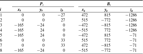
An improvement to suspension scheme 1 was made to testify the analysis above. The detailed parameters of P i and B i are shown in Table III. The four rear wires (W 1 , W 6 , W 2 , and W 7 ) are the same as scheme 1, and the front four wires were evenly attached to the fuselage, as shown in Figure 5.
The hinge points Pi and Bi of scheme 2.

Suspension scheme 2 for WDPR-8.

T min and T max are assigned the same value as in suspension scheme 1, and the diagonal stiffness matrix diag(K)2 of WDPR-8 in Figure 5 is calculated according to (32)
 \begin{align} diag\!\left(K\right)_{2}=\left[9626,35534,21582,28,323,368\right]^{\prime} \end{align}
The result of suspension scheme 2 shows the slight increase of roll stiffness. The front view and the rear view of the suspension wires are shown in Figure 6 and Figure 7, respectively. The thick purple cross in Figure 6 represents the aircraft model, and the thick purple line in Figure 7 denotes a horizontal metal rod fixed to the aircraft model. The solid lines indicate the original position of the wires, and the dashed lines represent the new position of the wires when the aircraft model rotates a slight angle $\eta_{1}\ (\varphi_{1})$
.
$\eta_{1}\ (\varphi_{1})$
.
Front view of suspension scheme 2.

The hinge points Pi and Bi of scheme 3.

Rear view of suspension scheme 2.

Taking wire B
3
P
3
as an example, a reverse torque will act on the model by B
3
P
3
′ while the model rotates slight angle $\eta_{1}$
to reach the dashed line position, as shown in Figure 6, resulting a decrease in the roll stiffness because of the unilateral characteristics of the wires. Similar situations also occur in the four rear wires in Figure 7. When the model rotates a slight angle
$\eta_{1}$
to reach the dashed line position, as shown in Figure 6, resulting a decrease in the roll stiffness because of the unilateral characteristics of the wires. Similar situations also occur in the four rear wires in Figure 7. When the model rotates a slight angle $\varphi_{1}$
to the dotted line position, reverse torques will in the four wires and decrease the roll stiffness.
$\varphi_{1}$
to the dotted line position, reverse torques will in the four wires and decrease the roll stiffness.
Further analysis shows that the rear four wires provide more torque to change the angle of the model, because the attach point P
1 and P
6 (P
2 and P
7) will provide longer force arms compared with P
3 and P
4 (P
5 and P
8), as shown in Figure 6 and Figure 7. When the roll angle $\varphi_{1}$
is greater than
$\varphi_{1}$
is greater than $\varphi_{2}$
, positive torque cannot be provided by the four rear wires for the unilateral tension characteristic of the wires. Thus, the possible improvement direction to raise the roll stiffness is to increase the angle φ
2
between the traction rope and the horizontal support rod, as shown in Figure 7.
$\varphi_{2}$
, positive torque cannot be provided by the four rear wires for the unilateral tension characteristic of the wires. Thus, the possible improvement direction to raise the roll stiffness is to increase the angle φ
2
between the traction rope and the horizontal support rod, as shown in Figure 7.
5.2.3. Suspension scheme 3
Suspension scheme 3 and the corresponding hinge points are designed based on the analysis above as shown in Figure 8 and Table IV. The joint points on the aircraft model (P i ) are the same as in scheme 2, while the hinge points (B i ) on the frame are different.
Suspension scheme 3 for WDPR-8.

Substituting the parameters in Table III into (32), the diagonal stiffness matrix of suspension scheme 3 is calculated
 \begin{align} diag\!\left(K\right)_{3}=\left[23693,16924,44922,83,597,256\right]^{\prime} \end{align}
However increased obviously, calculation result indicates that the roll stiffness was still smaller than pitch and yaw stiffness, so did the pitch workspace. Top view of the suspension was shown in Figure 9 for further analysis, where the long purple line is the fuselage and the short purple line is the horizontal rod fixed on the fuselage.
The hinge points Pi and Bi of scheme 4.

Schematic of pitch workspace for suspension scheme 3.

5.2.4. Suspension scheme 4
As mentioned above, the rear four wires provide more torque to change the angle of the model. If the model is suspended in the form of the dashed line (wire P 1 B 1 ′- P 6 B 6 ′ and wire P 3 B 3 ′- P 5 B 5 ′), the pitch angle θ 1 will approach to θ 2 , which means that the pitch workspace will be greater than 90 degrees. Suspension scheme 4 was designed based on this assumption, as shown in Figure 10, and the corresponding hinge points are shown in Table V. The suspension wires were arranged in symmetrical diamond shape.
Suspension scheme 4 for WDPR-8.

According to Table V, the diagonal matrix of stiffness for scheme 4 is
 \begin{align} diag\!\left(K\right)_{4}=\left[20388,16255,56493,163,1073,734\right]^{\prime} \end{align}
The roll stiffness increased significantly, and the stability of the platform was simultaneously improved, indicating the feasibility of the improvement direction discussed above. At the same time, the workspace in pitch direction exceeds 60° according to the analysis in Figure 9.
5.2.5. Further discussion
The above analysis process was conducted at an angle of attack at 0°. The rotational stiffness in roll, pitch, and yaw direction under different angle of attack was calculated, and the results are shown in Figure 11. As illustrated in Figure 11, along with the angle of attack increases, the roll stiffness ascends, while the pitch and yaw stiffness descends slowly. However, the other stiffness is still greater than the roll stiffness when the angle of attack is under about 57°, and the overall stability of the system is guaranteed.
Stiffness of WDPR-8 under different angle of attack.

The comparison of stiffness under different suspension schemes discussed in previous chapter is in Figure 12. As depicted in Figure 12, the roll stiffness and pitch stiffness of the system gradually increase, while the yaw stiffness begins to decrease, and all the stiffness was significantly promoted in suspension scheme 4, improving stability of the WDPR as a suspension system in wind tunnel test, and validating the manipulator design method in this work, at least for the standard dynamic model in this paper. Besides, the wires were arranged symmetrically around the aircraft model. However, the wires that determine the yaw workspace are different from that of the workspace in other two direction. As a result, the variation trend of yaw stiffness is different from the trend of other two stiffness.
Comparison of rotational stiffness for different suspension schemes.

6. Experiment validation
In order to verify the analysis result of the four suspension scheme, a prototype of WDPR-8 was established for experiments, as shown in Figure 13. The prototype consists of braced frame, eight universal pulleys, eight wires, servo motors, ball screw assemblies, a control cabinet, a aircraft model, as well as a vision measurement system which uses a monocular camera to capture the real-time pose of aircraft model. The aircraft model was suspended in the form of suspension scheme 4, as shown in Figure 10 and the parameters in Table V.The diving wires were arranged in a diamond shape as discussed in suspension scheme 4.
WDPR-8 prototype for experiment.

Worspace test of suspension scheme 4.

The brace frame of the prototype was constructed using aluminum alloy (No. 6060). In Figure 13, there are eight driving components mounted on the eight horizontal bars of the frame, each of which consists of a ball screw assembly, a servomotor, a driving wire, and a universal pulley. The slider on each ball screw assembly moves back and forth, driven by corresponding motors. Cables with excellent tensile strength and a diameter of 0.5 mm were chosen as the driving wires of the prototype. One end of a wire is attached to a joint point on the aircraft model, and the other end is connected to a slider through the universal pulley. The SDM model was suspended in the middle of the prototype using eight driving wires.
The length of eight wires was changed through the eight servo motors to control the attitude of the aircraft model. When the aircraft model rotates around O
b
x
b
, O
b
y
b
, and O
b
z
b
axis, the roll angle $\varphi$
, pitch angle θ, and yaw angle
$\varphi$
, pitch angle θ, and yaw angle $\psi$
were recorded while interference was about to occur between the model and wires, so as to obtain the workspace of the institution, as is shown in Figure 14.
$\psi$
were recorded while interference was about to occur between the model and wires, so as to obtain the workspace of the institution, as is shown in Figure 14.
Figure 14 shows the experimental results of workspace for suspension scheme 4. The experiments confirmed that the workspace in the pitch direction exceeds 60°, corroborating our analytical predictions, validating the analysis results in Figure 9 and the suspension design methods with the consideration of systematic stiffness and workspace.
7. Conclusions
In this study, an eight WDPR was used as an example to analyze the stiffness of the robot, and the stiffness expression determined by both the wire tension and the geometric structure of the suspension system was deduced. In addition, the suspension wire layouts of the robots with four different configurations were discussed in terms of the diagonal stiffness matrix analysis and, finally, a prototype of a WDPR-8 was established based on the analysis result. The workspace experiments were conducted, the test result was analyzed, and the following conclusions were drawn.
(1) In addition to workspace requirements, the stiffness of the system should be taken into consideration during the design procedure of a WDPR suspension system to improve the stability of the system.
(2) It is not suitable to place connecting points on the wings due to the fact that most aircraft models have thin wings. The suspension wires should be arranged as far away from the fuselage as possible to enhance the system stiffness. For models with symmetrical shapes, it is optimal to adopt a spatial symmetrical layout for the suspension wires.
(3) This research underscores the importance of considering both workspace requirements and system stiffness in the design of WDPR suspension systems. The optimal arrangement of suspension wires, particularly the diamond-shaped symmetrical layout, offers a large workspace and enhanced stiffness, making it a viable option for wind tunnel applications.
While the design requirements outlined here are specific to the SDM support scheme discussed in this paper, they can be broadly applied to the development of wind tunnel suspension systems for a range of models. The design procedure based on this can greatly improve the design and study efficiency of a WDPR support system in wind tunnel test, which is of great significance for the engineering application of WDPRs in wind tunnels.
In future study, WDPR-8 with different aircraft models will be installed in a low-speed wind tunnel to test the performance of the suspension system. Besides, the variable stiffness control of the WDPR will be realized based on more efficient wire tension solution. As a result, the stiffness and workspace will be expected to be improved. Possible singularity in workspace will have influence on the function of the robot which also need to be studied. These works will greatly improve the stability and accuracy of the WDPR as a suspension system in wind tunnel test.
Author contribution
Qi Lin conceived and designed the study. Miaojiao Peng designed the experiments and conducted data gathering. Yangfeng Ji performed statistical analyses and wrote the article.
Financial support
The research was facilitated by grants from the National Natural Science Foundation of China (№11472234 and №11072207), the Natural Science Foundation of Fujian Province (№2021J05164), and the Scientific Research Foundations of Jimei University, Chengyi College (JMT00117).
Competing interests
The author(s) declare none.
Ethical standards
The authors assert that all procedures contributing to this work comply with the ethical standards of the relevant national and institutional committees on human experimentation and with the Helsinki Declaration of 1975, as revised in 2008. The authors assert that all procedures contributing to this work comply with the ethical standards of the relevant national and institutional guides on the care and use of laboratory animals.


 Open access