


1 Introduction
The European fusion roadmap (see EUROfusion 2018) envisages the construction of a DEMO (DEMOnstration fusion power plant), which should demonstrate the technical and economic viability of commercial fusion power plants. DEMO is expected to generate between 300 and 500 MW of net electrical power to the grid. In DEMO, heating and current drive systems must be cost-effective and have a high wall plug efficiency. One such system is ion cyclotron resonance frequency (ICRF) heating, whose capabilities have been demonstrated in numerous fusion experiments (ITER Physics Basis Expert Group on Energetic Particles, Heating and Current Drive & ITER Physics Basis Editors 1999). In particular, efficient ion heating in DT plasmas has been demonstrated experimentally on JET and TFTR (Wilson et al. Reference Wilson, Bush, Darrow, Hosea, Jaeger, Majeski, Murakami, Phillips, Rogers and Schilling1995; Start et al. Reference Start, Jacquinot, Bergeaud, Bhatnagar, Cottrell, Clement, Eriksson, Fasoli, Gondhalekar and Gormezano1998, Reference Start, Jacquinot, Bergeaud, Bhatnagar, Conroy, Cottrell, Clement, Ericsson, Eriksson and Fasoli1999; Jacquet et al. Reference Jacquet, Lerche, Mantsinen, Van Eester, Kirov, Mantica, Gallart, Taylor, Kazakov and Monakhov2023). Furthermore, ICRF heating has additional applications such as prevention of high-Z impurity accumulation, sawtooth control, wall conditioning, etc. (Chapman Reference Chapman2010; Lyssoivan et al. Reference Lyssoivan, Douai, Koch, Ongena, Philipps, Schüller, Van Eester, Wauters, Blackman and Bobkov2012; Lerche et al. Reference Lerche, Goniche, Jacquet, Van Eester, Bobkov, Colas, Giroud, Monakhov, Casson and Rimini2016). However, the primary task of the ICRF system in a fusion reactor is to heat the ions sufficiently to bring the plasma (close) to ignition, where heating from the alpha particles is sufficient to sustain the fusion reactions. It has been shown experimentally that it is difficult to reach high central ion temperature with dominant electron heating for medium-sized devices (Beurskens et al. Reference Beurskens, Angioni, Bozhenkov, Ford, Kiefer, Xanthopoulos, Turkin, Alcusón, Baehner and Beidler2021), but it is not yet established how this extrapolates to large devices. It is also an open question whether ICRF heating will be needed for the transition to H-mode (Tran et al. Reference Tran, Agostinetti, Aiello, Avramidis, Baiocchi, Barbisan, Bobkov, Briefi, Bruschi and Chavan2022).
ICRF heating has the potential to provide both dominant ion and dominant electron heating, depending on the plasma scenario and antenna settings. Different ICRF heating scenarios in DEMO have been covered in detail by Van Eester et al. (Reference Van Eester, Lerche, Ragona, Messiaen and Wauters2019). A general trend, however, is that as the plasma temperature increases and approaches fusion relevant temperatures, electron damping increases at the expense of ion damping. This is particularly true in plasmas with large cross-sections, such as DEMO. In principle, the high temperature can be compensated for by lowering the parallel wavenumber $k_\parallel$ to keep the electron damping low, as the electron damping depends on the ratio between the parallel phase velocity $\omega /k_\parallel$
 and the parallel thermal velocity. Nevertheless, the antenna should not excite too low parallel wavenumbers, as this could result in propagating coaxial modes in the scrape-off layer. However, launching the wave along the poloidal component of the magnetic field results in an up- or downshift in the parallel wavenumber, depending on the orientation of the magnetic field, and thus enhances or reduces the electron damping, respectively.
The importance of the effect of the poloidal magnetic field and the resulting shift in $k_\parallel$ has been established by Perkins (Reference Perkins1977), who showed that the finite parallel gradient of the magnetic field gives rise to mode conversion from the fast magnetosonic wave to the ion cyclotron and ion Bernstein waves at the ion–ion hybrid layer. The physics of the up- and downshift has since been incorporated in full-wave solvers such as TORIC (see e.g. Brambilla Reference Brambilla1999) using poloidal Fourier decomposition. The shift in $k_\parallel$
 can also be approximated using simplified models, where the parallel wavenumber is estimated using the gradient of one of the electric field components (Jaun et al. Reference Jaun, Appert, Vaclavik and Villard1995; Hellsten et al. Reference Hellsten, Hannan, Johnson, Eriksson, Höök and Villard2013). Such models may be appropriate for large fusion devices such as ITER and DEMO, where ICRF heating is firmly situated in the minority heating regime and mode conversion is usually negligible. More recently, it has been shown that it is possible to account for both the spectral width and the shift in $k_\parallel$
 by adding correction terms to the wave equation iteratively (Zaar et al. Reference Zaar, Johnson, Bilato and Vallejos2024). This method showed good agreement with TORIC in ITER scenarios with little or negligible mode conversion.
Apart from heating, the ICRF system can be used for fast wave current drive (FWCD) during flat-top operation. Combined with significant bootstrap current, this permits extended pulses or, in principle, even steady-state operation (Federici et al. Reference Federici, Giruzzi, Lowry, Kemp, Ward, Wenninger and Zohm2013). The potential for FWCD in DEMO has been thoroughly investigated by, for example, Kazakov et al. (Reference Kazakov, Van Eester, Wauters, Lerche and Ongena2014) and Brambilla & Bilato (Reference Brambilla and Bilato2015). Kazakov et al. consider FWCD using an antenna mounted in the ceiling of the device and compare it with a more conventional launch position in the equatorial plane. The top launch configuration was able to provide enhanced current drive due to a combination of downshifted parallel wavenumber (resulting in improved current drive efficiency) and dominant electron damping by launching the wave between the ion resonances.
As an alternative to the phased array antennae used in many contemporary tokamaks (Messiaen et al. Reference Messiaen, Koch, Weynants, Dumortier, Louche, Maggiora and Milanesio2010; Durodié et al. Reference Durodié, Nightingale, Mayoral, Ongena, Argouarch, BergerBy, Blackman, Cocilovo, Czarnecka and Dowson2012; Bobkov et al. Reference Bobkov, Balden, Bilato, Braun, Dux, Herrmann, Faugel, Fünfgelder, Giannone and Kallenbach2013; Bourdelle et al. Reference Bourdelle, Artaud, Basiuk, Bécoulet, Brémond, Bucalossi, Bufferand, Ciraolo, Colas and Corre2015; Lin, Wright & Wukitch Reference Lin, Wright and Wukitch2020), it has previously been proposed to use a travelling wave array (TWA) antenna (Ragona & Messiaen Reference Ragona and Messiaen2016; Noterdaeme et al. Reference Noterdaeme, Messiaen, Ragona, Zhang, Bader, Durodié, Fischer, Franke, Smigelskis and Ongena2019; Ragona et al. Reference Ragona, Messiaen, Ongena, Van Eester, Van Schoor, Bernard, Hillairet and Noterdaeme2020). A TWA antenna consists of an array of mutually coupled elements distributed toroidally along the wall of the device, permitting the wave to travel along the extent of the TWA. Due to the distributed array elements, a TWA antenna may have a larger surface area (and thus a lower surface power density for a given voltage) than a port plug antenna. This allows for higher power coupling, larger distance between antenna and plasma, and/or lower electric fields on the antenna, which makes the TWA particularly suitable for large devices. In a reactor such as DEMO, the array elements may be embedded in the breeding blanket, minimizing the effect on the tritium breeding ratio (Ragona et al. Reference Ragona, Maquet, Bader, Batal, Bernard, Chen, Courtois, Delaplanche, Dumont and Durand2023).
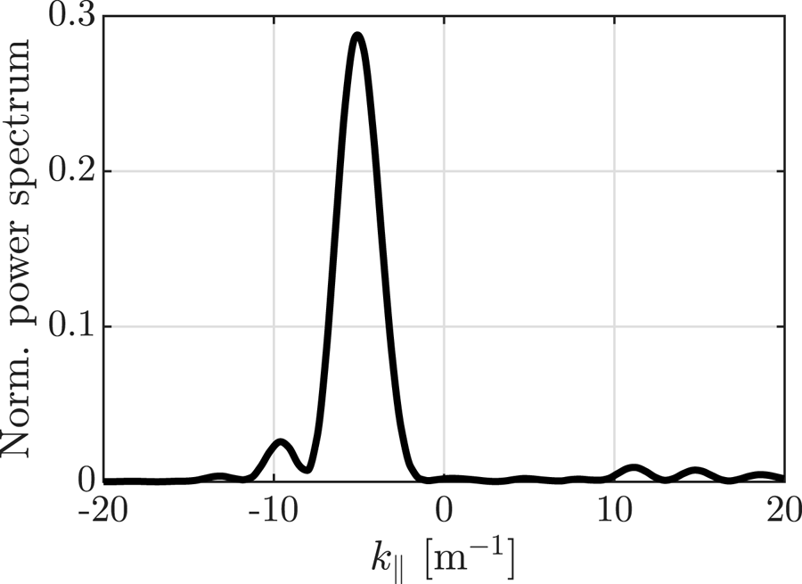
The TWA antenna is characterised by a unidirectional and narrow power spectrum (compared with phased array antennae), making it suitable for both FWCD and localised power deposition in the plasma core (Moeller, Chiu & Phelps Reference Moeller, Chiu and Phelps1992). An example of such a spectrum is shown in figure 1. Note that the spectrum has been tuned to avoid coaxial modes in the scrape-off layer that may arise due to low $|k_\parallel |$ . This particular spectrum comes from the mock-up of the TWA antenna for WEST (Maquet et al. Reference Maquet, Ragona, Durodié, Hillairet and Milanesio2023), but the spectrum can be tuned to better suit the needs of a larger device such as DEMO. Mounting the TWA antenna in an elevated position with respect to the equatorial plane, it is possible to exploit the unidirectional spectrum and downshift the entire incoming wave, hence reducing electron damping. This system would, in principle, be able to couple more power directly to the ions during the ramp-up phase, while also being able to provide FWCD later during flat-top operation. This study aims to exploit the downshift to explore the possibilities of enhanced heating and current drive using a single system.
Normalised power spectrum for a TWA antenna.
The remainder of the paper is organised as follows. In § 2, we investigate the potential for ion heating using a TWA antenna mounted in a few different positions in the poloidal plane. We consider temperatures between 10 and 30 keV and include collisional redistribution of the accelerated ions. We then investigate the prospects for FWCD in § 3 to see if enhanced ion heating can be combined with efficient current drive for these antenna positions. Section 4 contains a summary and discussion of the results.
2 Full-wave modelling of ion cyclotron heating with the TWA
To demonstrate that the downshift in $k_\parallel$ can enhance ion heating and current drive efficiency, we simulate four different mounting positions of the TWA in a large DEMO-like plasma with a major radius of 9.38 m and an on-axis magnetic field of 5.1 T. The antennae are centred at the poloidal angles $0^\circ$
 , $23^\circ$
 , $45^\circ$
 and $67^\circ$
 (with respect to the centre of the vacuum vessel). These positions are referred to as positions 1 to 4, respectively, and are illustrated in figure 2. Note that in this work, the scrape-off layer is modelled as a vacuum, hence the discontinuity in the electric field across the last closed flux surface. With both toroidal field and plasma current oriented clockwise, the wave is upshifted below the equatorial plane and downshifted above the equatorial plane (assuming that $\phi$
 runs anticlockwise and that $n_\phi > 0$
 ). For equatorial launch, the total effect of the shift leads to a broadening of the poloidal wave spectrum, but the effect on power deposition is negligible (Zaar, Johnson & Vallejos Reference Zaar, Johnson and Vallejos2023). As the antenna is moved off the equatorial plane, the whole wave is increasingly downshifted.
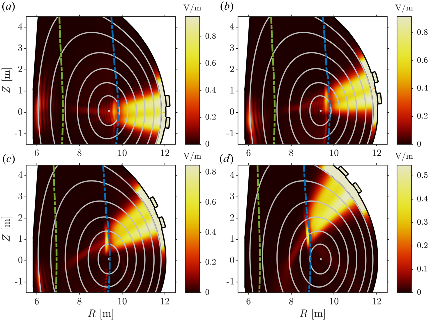
Magnitude of the left-hand polarised component $E_+$ for positions 1–4 shown in panels (a)–(d), respectively. Here, $T_0 = 20\,{\rm keV}$
 and $n_\phi = 43$
 . Green curves denote deuterium cyclotron resonances ($n = 1$
 ) and blue curves denote tritium/helium-3 cyclotron resonances ($n = 2/1$
 ).
).
The effect of the downshifted antenna spectrum on the propagation and damping of the fast magnetosonic wave is quantified using the full-wave solver FEMIC (Vallejos et al. Reference Vallejos, Johnson, Ragona, Hellsten and Frassinetti2019). FEMIC has recently been updated (see Zaar et al. Reference Zaar, Johnson, Bilato and Vallejos2024) with an iterative method to account for the effect of the poloidal magnetic field on the parallel wavenumber
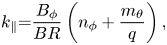
where
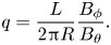
Here, $R$ is the major radius, $L$
 is the circumference of the local flux surface, and $n_\phi$
 and $m_\theta$
 are toroidal and poloidal mode numbers, respectively. Additionally, $B_\phi$
 and $B_\theta$
 denote the toroidal and poloidal components of the magnetic field, and $B = (B_\phi ^2 + B_\theta ^2)^{1/2}$
 . The poloidal mode number $m_\theta$
 is defined through the Fourier decomposition of the electric wave field, such that
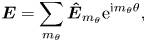
where $\theta$ is an equal-arc-length angle.
To see how efficiently the ions are heated during the ramp-up phase of the plasma, we are considering core temperatures (equal for ions and electrons) between 10 and 30 keV. The plasma consists of equal parts deuterium and tritium with a small $^3$ He minority (1 %) to improve the ion damping. The density is kept constant as the temperature is increased. To avoid excessively energetic ions, the frequency for positions 1 and 2 is tuned to place the cyclotron resonance slightly off-axis, near $\rho _\mathrm {pol} = 0.2$
 in the equatorial plane, which corresponds to the antenna frequency $f = 50\,{\rm MHz}$
 . In this work, $\rho _\mathrm {pol}$
 is used to denote the square root of the normalised poloidal flux. For positions 3 and 4, the antenna frequency is set such that power deposition is as central as possible. This corresponds to $f = 52\,{\rm MHz}$
 and $f =55\,{\rm MHz}$
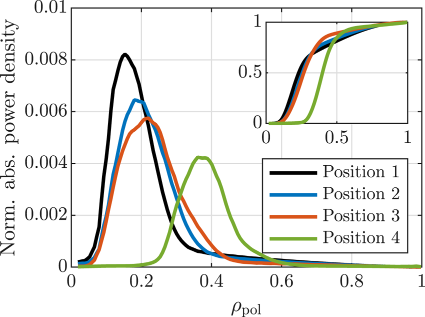
 , respectively. Power deposition profiles for $n_\phi = 43$
 can be seen in figure 3 for positions 1–4. The power deposition profiles are indeed peaked around $\rho _\mathrm {pol} = 0.2$
 for antenna positions 1–3, whereas it is peaked near $\rho _\mathrm {pol} = 0.4$
 for position 4.
Normalised flux surface average of the absorbed power density for $T_0 = 20\,{\rm keV}$ and $n_\phi = 43$
 . Inset shows the integrated power deposition.
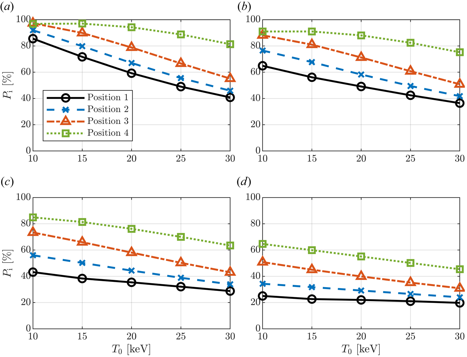
To understand how the downshift affects the electron damping, the fraction of the power absorbed by the ions, $P_\mathrm{i}$ , is plotted versus temperature in figure 4(a). Here, we set $n_\phi = 43$
 , which is one of the dominant toroidal mode numbers in a power spectrum tuned for low parallel wavenumbers. At $T_0 = 10\,{\rm keV}$
 , electron damping is weak and almost all power is absorbed by the ions for all antenna positions. The electron damping then increases with the temperature such that most of the wave energy is damped by the electrons for antenna positions 1 and 2. Electron damping is slightly weaker for position 2 than the equatorial launch due to the modest downshift in $k_\parallel$
 . In contrast, antenna positions 3 and in particular 4 largely retain their ability to deposit the majority of the wave energy on the ions all the way up to $T_0 = 30\,{\rm keV}$
 . In fact, for position 4, even at $T_0 = 20\,{\rm keV}$
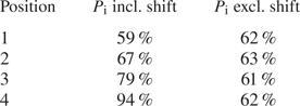
 , approximately 94 % of the power is absorbed by the ions. This is attributed to the stronger downshift, as illustrated in table 1. Here, the fraction of absorbed power for the four antenna positions is summarised for $T_0 = 20\,{\rm keV}$
 and $n_\phi = 43$
 including and excluding the shift in the parallel wavenumber. The importance of the shift is similar for all probed temperatures, and it is evident that accounting for the effect of the poloidal magnetic field is essential for the modelling in this work.
(a) Absorbed power partition and (b–d) power partition after collisional redistribution for (b) 50 MW, (c) 100 MW, and (d) 200 MW coupled power for $n_\phi = 43$ .
.
Fraction of total coupled power absorbed by ions, $P_\mathrm{i}$ , including and excluding the shift in $k_\parallel$
 for $T_0 = 20\,{\rm keV}$
 and $n_\phi = 43$
 .
.
As the energetic minority and tritium ions collide with the background plasma, the plasma is heated. To quantify the collisional power redistribution, electric fields and power deposition profiles from FEMIC are fed into the Foppler code. Foppler is a one-dimensional pitch angle averaged Fokker–Planck solver for ICRF heating that contains Doppler physics and an ad hoc model for the pitch angle distribution, based on the Dendy model (see Dendy et al. Reference Dendy, Hastie, McClements and Martin1995). The distribution function is assumed to be isotropic below the critical energy and becomes exponentially narrower around $\mu = E/B_\mathrm {res}$ , which is the magnetic moment of an orbit with turning points on the unshifted cyclotron resonance. A detailed description of the Foppler code and the pitch angle distribution will be presented in a future publication by Bähner et al. Note that in this work, there is no self-consistent coupling between FEMIC and Foppler.
The collisional power redistribution is evaluated for a few different values of the total coupled power. As shown in figure 4(b–d), position 4 (and to some extent position 3) is able to deliver significantly more ion heating for all probed temperatures and power levels compared with equatorial launch. In particular, for 100 MW and 200 MW of coupled power, the ions are heated more than twice as much by an antenna located in position 4 than position 1. Also for 50 MW, the ions are heated twice as much for higher temperatures, and approximately 50 % more for $T_0 = 10\,{\rm keV}$ and 15 keV. Position 3 also delivers significantly enhanced ion heating, whereas the improvement with position 2 is more modest.
It is evident from figure 4 that absorbed power partition alone does not explain the enhanced ion heating for the downshifted waves. At $T_0 = 10\,{\rm keV}$ , the absorbed power partition is fairly similar for all four launch positions, whereas the ion heating differs significantly. The main contributor to this discrepancy is the flux surface averaged power deposition, as higher absorbed power densities lead to more energetic tails in the distribution functions. Ions with energies above the critical energy are mainly slowed down by (and are thus heating) electrons (Stix Reference Stix1972).
Although the power deposition profiles are peaked near the same flux surface for positions 1–3, we observe in figure 3 that the maximum flux averaged absorbed power density becomes lower as we elevate the antenna. This is partially explained by the alignment of the resonance and the flux surfaces where the wave is absorbed. For position 1, we see in figure 2(a) that the resonance is somewhat tangential to the flux surface where the wave is damped. For position 3, however, we see in figure 2(c) that the resonance is completely perpendicular to the central flux surfaces. This spreads the wave front over a wider range of flux surfaces, lowering the power density. This effect is most prominent at lower temperatures. As the temperature increases, the resonance layers are broadened, widening the power deposition profile for position 1 as well.
At $T_0 \gtrsim 20\,{\rm keV}$ , the enhanced ion heating is mainly explained by the more favourable absorbed power partition. Note that for geometrical reasons, the antenna in position 4 deposits its power around $\rho _\mathrm {pol} = 0.4$
 , rather than $\rho _\mathrm {pol} = 0.2$
 , further reducing the flux surface averaged power deposition compared with the other positions. Heating the plasma this far off-axis may not be desirable.
3 Current drive prospects
The downshift in the parallel wavenumber that permits dominant ion absorption may also be beneficial for FWCD. A higher parallel phase velocity $\omega /k_\parallel$ means that the fast magnetosonic wave resonates with electrons with higher parallel velocity, which in turn have a lower collisionality. However, Landau damping and transit-time magnetic pumping decay exponentially with the parallel phase velocity, as there are fewer electrons to accelerate. Hence, there is a trade-off between current drive efficiency and strong electron damping, which both are desirable for efficient current drive. In this section, we investigate the fast wave current drive prospects for the four mounting positions of the TWA antenna described in § 2.
3.1 Current drive model
In this work, we have implemented a local parametrised current drive (CD) efficiency $\eta = \eta (\psi,\theta )$ (see Ehst & Karney Reference Ehst and Karney1991) on the form
where $f_\mathrm {neo}$ is the neoclassical correction factor for trapped electrons, $\eta ^*$
 is a normalisation constant and $\eta _0$
 is the dimensionless parametrised straight-field CD efficiency. Ehst & Karney (Reference Ehst and Karney1991) evaluate the radio frequency (RF) driven current assuming a ray tracing description of the wave. To adapt their model to a full-wave solution, the driven current density along the magnetic field, denoted by $J_{\parallel,\mathrm {CD}}$
 , is in this work implicitly expressed as
where $V(\psi )$ is the volume contained by the flux surface $\psi$
 , $Q_\mathrm{e}(\psi,\theta )$
 is the RF power density absorbed by the electrons and $\langle \cdot \rangle$
 denotes flux surface average. The flux averaged toroidal RF-driven current density $J_\mathrm {CD}(\psi )$
 can then be written as

where $f_\mathrm {geom}(\psi ) = F(\psi )\langle R^{-2} \rangle /\langle B \rangle \langle R^{-1} \rangle$ is a geometrical factor that depends on the magnetic field geometry and $F(\psi ) = RB_\phi$
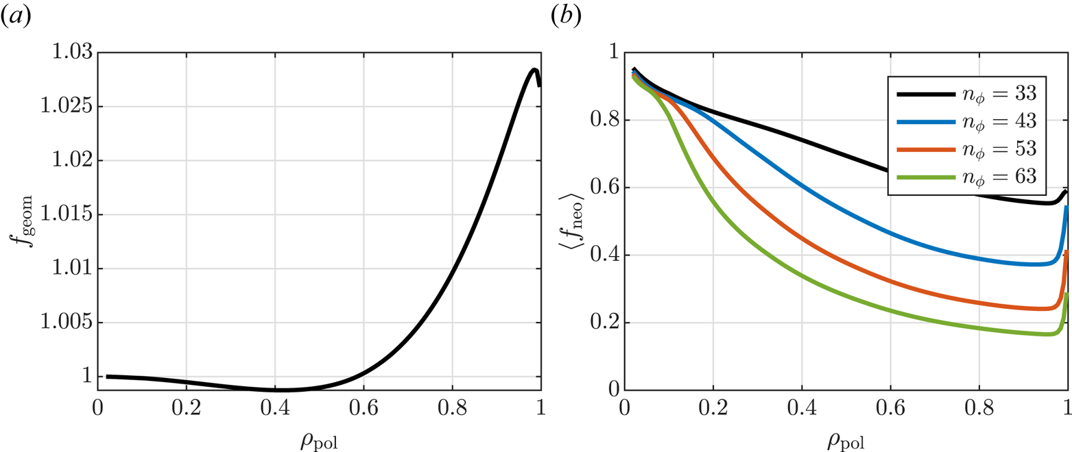
 . The effect of the correction factors $f_\mathrm {geom}$
 and $f_\mathrm {neo}$
 on the current drive efficiency is illustrated in figure 5, where they are plotted as functions of $\rho _\mathrm {pol}$
 . We see that $f_\mathrm {geom}$
 is near unity everywhere, and that $\langle f_\mathrm {neo} \rangle$
 is significantly smaller than unity outside the very centre of the plasma due to the effect of trapped electrons. Here, $f_\mathrm {neo}$
 has been evaluated for $m_\theta = 0$
 . It is apparent that off-axis current drive rapidly becomes less efficient as the toroidal mode number (and thus $k_\parallel$
 ) increases.
(a) Geometric and (b) neoclassical correction factors for current drive efficiency.
When accounting for parallel dispersion, FEMIC evaluates the absorbed power density as

where $\boldsymbol {\hat {\chi }}$ is the quasi-homogeneous susceptibility tensor in Fourier space (see Stix Reference Stix1992; Brambilla Reference Brambilla1998; Swanson Reference Swanson2003), $\boldsymbol {E} = \boldsymbol {E}(\psi,\theta )$
 is the electric wave field and $m_\theta$
 is the poloidal mode number. Here, caret denotes Fourier transform. To include the up- and downshift in the parallel wavenumber when evaluating the FWCD, we use a quasi-homogeneous current drive efficiency $\eta (\psi,\theta,m_\theta )$
 , where $k_\parallel$
 is evaluated using (2.1), hence the dependency on $m_\theta$
 . The flux averaged toroidal RF-driven current density then becomes

3.2 Full-wave modelling results for FWCD
To maximise the single pass electron damping, the antenna frequency is increased to move the second harmonic tritium resonance as far away from the antenna as possible without having the second harmonic deuterium/alpha resonance enter the antenna box. In practice, alpha particles may resonate far away from the ‘cold’ resonance due to significant Doppler shift. Hence, care must be taken such that fast ions are not accelerated in front of the antenna (Hannan, Hellsten & Johnson Reference Hannan, Hellsten and Johnson2013). In this work, we set the antenna frequency to $f = 59\,{\rm MHz}$ for positions 1–3 and $f = 63\,{\rm MHz}$
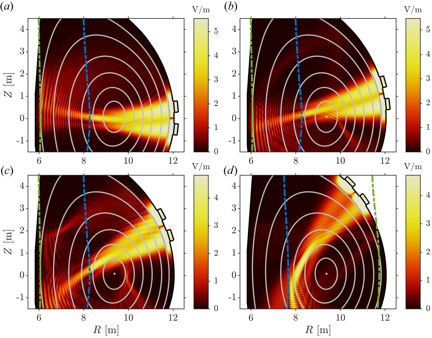
 for position 4. The resulting electric fields are visualised in figure 6. Note that the difference between the frequencies used for heating and current drive operation coincides with the bandwidth of the TWA antenna concept proposed by Ragona et al. (Reference Ragona, Messiaen, Ongena, Van Eester, Van Schoor, Bernard, Hillairet and Noterdaeme2020). As previously stated, increasing the frequency further is not desirable. However, it could be valuable to be able to position the minority resonance further on the low field side during the ramp-up phase.
Electric field norm for positions 1–4 shown in panels (a–d), respectively. Here, $T_0 = 30\,{\rm keV}$ and $n_\phi = 53$
 . Green curves denote deuterium cyclotron resonances ($n = 1$
 in panels a–c and $n = 2$
 in panel d) and blue curves denote tritium cyclotron resonances ($n = 2$
 ).
).
The RF-driven current is computed assuming a plasma consisting of deuterium and tritium in equal parts. Diluting the plasma with helium ashes does not strongly affect the wave propagation properties, but using the scaling relation from Kazakov et al. (Reference Kazakov, Van Eester, Wauters, Lerche and Ongena2014), we find that increasing $Z_\mathrm {eff}$ to 1.2 (corresponding to 10 % helium ash concentration) reduces $\eta$
 by approximately 10 %. At $Z_\mathrm {eff} = 1.5$
 , the current drive efficiency is reduced by approximately 20 %.
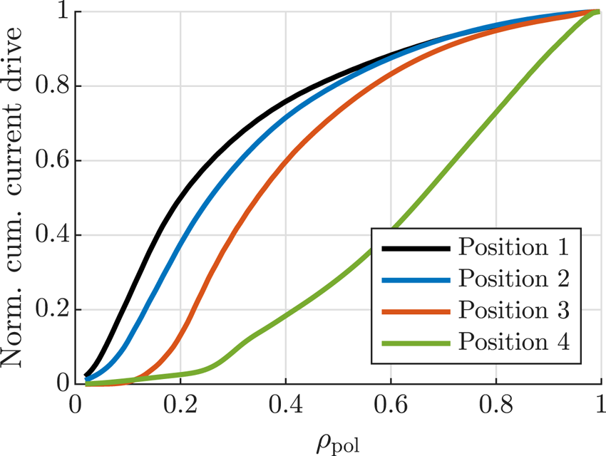
Normalised current drive profiles for positions 1–4 evaluated for $n_\phi = 53$ are shown in figure 7. As expected, moving the antenna off the equatorial plane also moves the RF-driven current off-axis. For position 2, this effect is negligible, 80 % of the current is still driven inside $\rho _\mathrm {pol} = 0.5$
 , compared with $\rho _\mathrm {pol} = 0.45$
 for equatorial launch. For position 4, however, the single-pass electron damping is low due to the downshift in $k_\parallel$
 , and we have significant current drive everywhere from $\rho _\mathrm {pol} = 0.25$
 out to the last closed flux surface. Which current drive profile is the most appropriate for a given scenario depends on the bootstrap current and the availability of electron cyclotron heating.
Normalised integrated current drive profiles for $n_\phi = 53$ .
.
Both electron damping and current drive efficiency are sensitive to the parallel wavenumber. The electron power partition and total driven current are evaluated over a range of $n_\phi$ and shown in figure 8. It is evident that the equatorial plane launch is efficient for driving current at lower toroidal mode numbers. This is possible due to a large fraction of electron absorption combined with high current drive efficiency $\eta$
 (due to low $k_\parallel$
 ). Position 3 (and to a smaller extent, position 2) suffers from weak electron damping due to the downshift in $k_\parallel$
 . This is also reflected in the total integrated current in figure 8(b). Position 4 has significantly better electron damping than position 3 despite the larger downshift. This is attributed to the launch angle of the wave and higher antenna frequency $\omega$
 , which causes the wave to partially miss the tritium resonance, allowing more energy to be absorbed by the electrons. However, as the wave never reaches the innermost flux surfaces (see figure 6d), the current drive efficiency $\eta$
 is limited by trapped electrons (see figure 5).
(a) Electron power partition and (b) total driven current evaluated over a range of $n_\phi$ . The grey dotted curve sketches the power spectrum for a relevant TWA antenna (in arbitrary units).
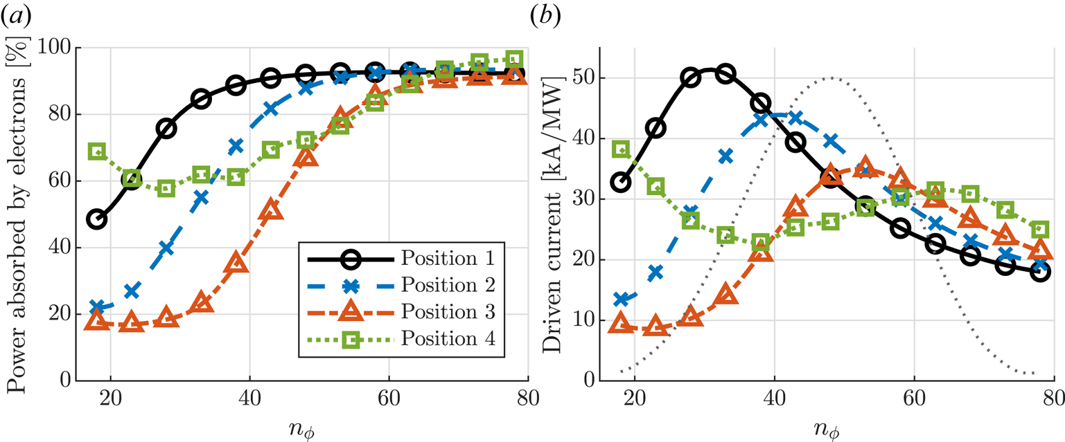
Moving to higher toroidal mode numbers, electron damping increases and a similar fraction of electron absorption $(P_\mathrm{e} > 90\,\%)$ is obtained for all antenna positions. The total driven current is then largely determined by the current drive efficiency, which is highest for antenna positions 3 and 4. It is noteworthy that for position 4, the total driven current does not change much across the most relevant parts of the toroidal spectrum, whereas the total driven current achieved using positions 2 and 3 is clearly peaked around $n_\phi = 43$
 and $n_\phi = 53$
 , respectively. To maximise the RF-driven current for these positions, the antenna spectrum should be tuned so that it peaks around these values of $n_\phi$
 as well.
The total driven current can be estimated by summing over all toroidal modes $n_\phi$ (neglecting coupling between toroidal modes), weighted by the normalised antenna power spectrum. For the spectrum shown in figure 8, we obtain approximately 35, 36, 28 and $27\,{\rm kA}\,{\rm MW}^{-1}$
 for positions 1–4, respectively.
4 Discussion and conclusions
In this study, we demonstrate that it is possible to enhance ion heating in a DEMO-like plasma by launching the ICRF wave from a mounting position elevated off the equatorial plane using a unidirectional antenna spectrum. The enhanced ion heating is made possible due to a downshift in $k_\parallel$ as the wave propagates along the poloidal magnetic field, resulting in decreased parasitic electron damping before the wave reaches the ion cyclotron resonance.
By tuning the frequency, the same system can be used for FWCD during flat-top operation. Whereas phased array antennae use different toroidal spectra for heating and current drive, the antenna spectrum of the TWA antenna is not a free parameter. The spectrum is linked to the dispersion relation of the antenna structure and varies with the frequency (Messiaen & Ragona Reference Messiaen and Ragona2017), but the peak of the spectrum does not change much unless specifically designed to do so. In principle, the phase difference between the array elements can be chosen to increase the dispersion of the antenna spectrum, so that the peak of the spectrum moves across the frequency band. However, this avenue has not yet been fully explored for these applications.
As opposed to the ramp-up phase, strong electron damping is desirable for FWCD. However, the downshift in $k_\parallel$ improves current drive efficiency, hence creating a trade-off between high efficiency and electron absorption. We find that compared with the equatorial launch, this reduces the total driven current for lower toroidal mode numbers and enhances the total driven current for higher mode numbers, where electron damping is sufficiently strong despite the downshift. There is almost an inverse relationship between efficient ion heating and current drive. However, it is noteworthy that depending on the antenna spectrum, position 2 may be a slightly better option for both ion heating and FWCD than position 1. Although position 1 seems to allow for the highest driven current, it may not be possible to realise this potential. That would require an antenna with a power spectrum that peaks around $n_\phi = 30$
 . Furthermore, the power spectrum needs to be narrow to avoid exciting coaxial modes in the scrape-off layer.
Position 4 is qualitatively different from positions 1–3. As the antenna is located higher up, it is possible to increase the frequency further without having the deuterium/alpha resonance too close to the antenna. The wave may then be launched between the second harmonic tritium resonance and the second harmonic deuterium resonance, resulting in better electron absorption than position 3 for example, despite the stronger downshift for position 4. Increasing the frequency as much as possible is important for FWCD in general (Hannan et al. Reference Hannan, Hellsten and Johnson2013; Brambilla & Bilato Reference Brambilla and Bilato2015), but crucial for the success of this configuration. If the antenna frequency is not high enough, the wave will have a tangential resonance and therefore strong ion damping. This configuration is also sensitive to the triangularity of the plasma, as well as the shape of the vessel wall, and may or may not be realisable in a future DEMO machine, depending on the design. Position 4 resembles the configuration studied by Kazakov et al. (Reference Kazakov, Van Eester, Wauters, Lerche and Ongena2014), where the antenna was located in the ceiling. The authors found enhanced current drive compared with equatorial launch, which was possible due to more central electron absorption (and thus higher current drive efficiency) and very little ion damping. However, position 4 allows for ion heating during the ramp-up phase of the plasma, albeit further off-axis than the other configurations for geometrical reasons.
The ramp-up phase is, in this work, modelled using constant density and steady state equations and should rather be seen as a parameter sweep in temperature more than anything else. Ideally, this work should be complemented by a more detailed analysis containing transient effects and appropriate wave forms for DEMO. Moreover, to get a more complete picture of the heating of the plasma, the Fokker–Planck equation should be solved self-consistently with the wave equation to account for the anisotropic and non-Maxwellian distribution functions, as well as with transport equations. However, such analysis is deemed to be outside the scope of this paper.
Acknowledgements
The authors would like to thank L.-G. Eriksson for fruitful discussions and his insightful comments on the manuscript.
Editor P. Ricci thanks the referees for their advice in evaluating this article.
Funding
This work has been carried out within the framework of the EUROfusion Consortium, funded by the European Union via the Euratom Research and Training Programme (Grant Agreement No. 101052200 – EUROfusion). Views and opinions expressed are however those of the authors only and do not necessarily reflect those of the European Union or the European Commission. Neither the European Union nor the European Commission can be held responsible for them.
Declaration of interests
The authors report no conflict of interest.


 Open access