


Introduction
In recent years, the research in the field of joint communication and sensing (JCAS) became progressively more important. JCAS denotes the combination of sensing and communication into a single system. For both applications, the spectrum or even the waveform is shared, as the radio-frequency (RF) spectrum is a scarce and expensive resource. With the advance of software-defined radio, where the signal processing takes place in software, the implementation of the signal processing for both functionalities becomes easier [Reference Thomä, Dallmann, Jovanoska, Knott and Schmeink1]. A further reason for the integration of both functionalities into one system is the increasing sensor density, which entails increased mutual interference. Furthermore, shared hardware is a sustainable and resource efficient solution in the field of RF engineering.
This paper will focus on the integration of communication signals into a frequency-modulated continuous wave (FMCW) radar system with minimal effects on the radar performance. It can be used, e.g., in the field of traffic control and monitoring, especially in the development of driverless cars. It is a great chance to integrate communication signals into radar signals and to acquire another source of information in order to allow a safe traffic [Reference Thomä, Dallmann, Jovanoska, Knott and Schmeink1]. The vehicle-to-vehicle communication can also help to pass on information, e.g., about available parking spaces or short-term road closures and traffic jams [Reference Wild, Braun and Viswanathan2]. A major advantage of the proposed system is that the FMCW radars have a very high resolution but only require an analog-to-digital converter (ADC) with a moderate sampling rate. This makes the JCAS system the preferred choice for low data rates with moderate hardware requirements. This work is an extension of a paper presented at the European Radar Conference 2023 and published in its proceedings [Reference Faghih-Naini, Peters, Kurin, Reissland and Weigel3]. In this work, the setup was extended by introducing the communication receiver to broaden the perspective from the focus on radar analysis to the analysis of a whole JCAS system. Furthermore, the setup was optimized and additional measurements were performed. This paper focuses on the challenges which come along a hardware setup in this scenario. The phase noise, but also the slightly different frequencies of a input oscillator of the phase-locked loop (PLL) and its temperature dependency, influences the setup and the measurements results. The impact of the carrier frequency, the ramp length, and the frequency shift keying (FSK) deviation are evaluated in this paper and also an algorithm to extract the data the FSK data in the receiver is presented.
State of the art of FMCW-based JCAS systems
In literature, there are several approaches which integrate communication in an FMCW radar system. Besides theoretical approaches like [Reference Hossain, Elshafiey and Al-Sanie4, Reference Lampel, Tigrek, Alvarado and Willems5], there are different practical investigations of how to integrate communication into an FMCW radar. One suggestion is frequency multiplex, which means, that the communication uses another frequency band than the FMCW radar [Reference Johannes, Stanko and Kallfass6]. To investigate the approaches and compare them with the proposed system, this section focuses on comparable systems, which use the same waveform for communication and the FMCW radar signaling for this JCAS system.
One approach is to vary the start frequency of the FMCW chirps but stay within the same frequency band. This is proposed by Alabd et al. [Reference Alabd, de Oliveira, Nuss, Wiesbeck and Zwick7] using long-range modulation. For the integration of the communication functionality, the frequency chirps start at a different frequency for each distinct symbol. As soon as the highest frequency is reached, the chirp starts at the lowest frequency of the frequency band and increases again until the start frequency is reached. To detect the symbols at the receiver, the start frequency or the timing of the frequency shift is evaluated, as it is a measure for the sent symbol. In the publication, the concept is validated with measurements but no further investigations were mentioned [Reference Alabd, de Oliveira, Nuss, Wiesbeck and Zwick7].
A second approach involves in-chirp modulation, as published by Schreiblhofer et al. [Reference Scheiblhofer, Feger, Haderer, Scheiblhofer and Stelzer8]. The FMCW chirp is modulated with the communication signal by mixing the modulated FSK data with the transmission ramps. The symbol duration of the communication data is much shorter than the ramp period, which leads to higher data rates in the upper kbit/s range. This work investigates different symbol rates and modulation orders of the FSK signal and its effect on the radar performance. Marin et al. use the same principle in a publication [Reference Marin, Bernhardt, Heino and Riihonen10]. This work investigates the transmission parameter like transmitting power but also the order of the FSK and the symbol period. The last two parameters worsen the radar performance as well as a too low transmission power. Also the influence of a secondary radar as interferer was evaluated [Reference Marin, Bernhardt, Heino and Riihonen10].
Furthermore, JCAS can be realized using time division multiple access (TDMA). This is proposed by Moghaddasi et al. in [Reference Moghaddasi and Wu9]. They use a trapezoidal waveform for the radar signaling. A fourth of the time is reserved for the data transmission with a constant carrier frequency. This allows data rates up to 25 Mbit/s during the data transmission frame, which leads to an overall data rate of 6.25 Mbit/s [Reference Moghaddasi and Wu9]. Their publication focuses on the demonstration of the system, no further investigations are mentioned and discussed.
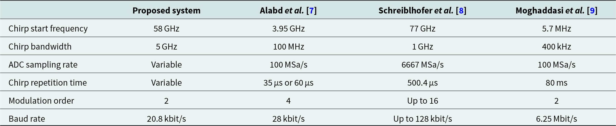
Wang et al. [Reference Wang and Altintas11] propose a short demo of the same approach used in this work: modulation of every FMCW chirp with a frequency shift for the data transmission. In contrast to this publication, they do not present any measurement data. Besides these approaches, there are other chirp modulation based approaches like [Reference Dwivedi, Zoli, Barreto, Sen and Fettweis12], which propose a new modulation signal in a simulation. The system parameters of the three introduced JCAS concepts are summarized in Table 1.
Comparison of the current and other state-of-the-art FMCW-based JCAS systems
Fundamentals
Before introducing the hardware setup, the differences between a typical FMCW radar and an FSK-modulated FMCW radar, which allows data transmission, are elaborated. The frequency of the transmission signal of a single chirp is defined by
 \begin{equation}
f_\text{FMCW}(t) = f_\text{rs} + \mu t,
\end{equation}
\begin{equation}
f_\text{FMCW}(t) = f_\text{rs} + \mu t,
\end{equation} where  $\mu = BW/T_\text{c}$ denotes the slope of the frequency chirp. BW is the bandwidth of the chirp and T c its duration. f rs represents the chirp starting frequency. The transmitted signal is [Reference Gamba13]
 \begin{equation}
s(t) = \cos{\phi_\text{FMCW}(t)}
\end{equation}
\begin{equation}
s(t) = \cos{\phi_\text{FMCW}(t)}
\end{equation}with
 \begin{equation}
\phi_\text{FMCW}(t) = 2\pi \left(f_\text{rs} t +\frac{1}{2} \mu t^2 \right) + \phi_0.
\end{equation}
\begin{equation}
\phi_\text{FMCW}(t) = 2\pi \left(f_\text{rs} t +\frac{1}{2} \mu t^2 \right) + \phi_0.
\end{equation}The FSK modulation adds an additional frequency offset to the frequency of the transmitted signal. The entire frequency term then becomes
 \begin{equation}
f(t) = f_\text{rs} + f_\text{car} + f_\text{FSK}(t) + \mu t.
\end{equation}
\begin{equation}
f(t) = f_\text{rs} + f_\text{car} + f_\text{FSK}(t) + \mu t.
\end{equation} f car is the carrier frequency of the FSK modulation and f FSK the frequency deviation caused by the FSK modulation. These two frequencies can be summarized to  $f_\text{com}(t) = f_\text{car} + f_\text{FSK}(t)$. That leads to the altered phase
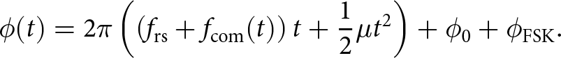 \begin{equation}
\quad \phi(t) = 2\pi \left(\left(f_\text{rs} + f_\text{com}(t)\right) t +\frac{1}{2} \mu t^2 \right) + \phi_0 + \phi_\text{FSK}.
\end{equation}
\begin{equation}
\quad \phi(t) = 2\pi \left(\left(f_\text{rs} + f_\text{com}(t)\right) t +\frac{1}{2} \mu t^2 \right) + \phi_0 + \phi_\text{FSK}.
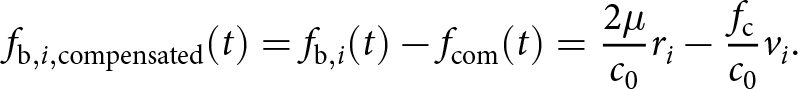
\end{equation}A schematic illustration of the transmitted signal is shown in Fig. 1. The transmitted signal is sent out, is reflected by the target and attenuated by the path loss. Therefore, the received signal r(t) can be described as
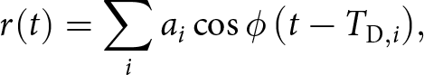 \begin{equation}
r(t) = \sum\limits_i a_i \cos{\phi\left(t-T_{\text{D},i}\right)},
\end{equation}
\begin{equation}
r(t) = \sum\limits_i a_i \cos{\phi\left(t-T_{\text{D},i}\right)},
\end{equation}where i are the indices of different targets which are characterized by a time delay T D and an attenuation a. In the mixer, the received signal is multiplied by the transmitted signal. This signal is filtered. Therefore, higher frequent signal parts can be ignored. The resulting signal is called beat signal and is described as
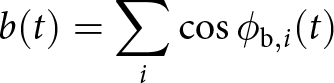 \begin{equation}
b(t) = \sum\limits_i \cos\phi_{\text{b},i}(t)
\end{equation}
\begin{equation}
b(t) = \sum\limits_i \cos\phi_{\text{b},i}(t)
\end{equation}with
 \begin{equation}
\begin{split}
\phi_{\text{b},i}(t) = 2\pi f_\text{rs}T_{\text{D},i}-2\pi\frac{1}{2} \mu T_{\text{D},i}^2+ 2\pi\left(\mu T_{\text{D},i}+f_\text{com}(t)\right)t
+\phi_\text{FSK}.
\end{split}
\end{equation}
\begin{equation}
\begin{split}
\phi_{\text{b},i}(t) = 2\pi f_\text{rs}T_{\text{D},i}-2\pi\frac{1}{2} \mu T_{\text{D},i}^2+ 2\pi\left(\mu T_{\text{D},i}+f_\text{com}(t)\right)t
+\phi_\text{FSK}.
\end{split}
\end{equation} The Doppler frequency  $f_{\text{D},i}=f_\text{rs}v_\text{i}/c_\text{0}$ also influences the beat signal f b. vi is the radial velocity of target i. Considering a moving target, the phase of the beat signal can be described as
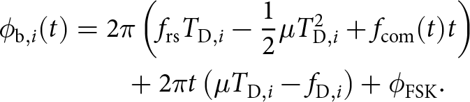 \begin{align}
\phi_{\text{b},i}(t) & = 2\pi\left(f_\text{rs}T_{\text{D},i}-\frac{1}{2} \mu T_{\text{D},i}^2 +f_\text{com}(t)t\right)\nonumber \\ & \qquad + 2\pi t\left(\mu T_{\text{D},i}- f_{\text{D},i}\right)+\phi_\text{FSK}.
\end{align}
\begin{align}
\phi_{\text{b},i}(t) & = 2\pi\left(f_\text{rs}T_{\text{D},i}-\frac{1}{2} \mu T_{\text{D},i}^2 +f_\text{com}(t)t\right)\nonumber \\ & \qquad + 2\pi t\left(\mu T_{\text{D},i}- f_{\text{D},i}\right)+\phi_\text{FSK}.
\end{align}The beat frequency at receiver side is
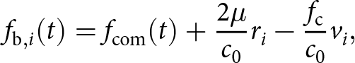 \begin{equation}
f_{\text{b},i}(t) = f_\text{com}(t)+\frac{2\mu}{c_0} r_{i}-\frac{f_\text{c}}{c_0} v_{i},
\end{equation}
\begin{equation}
f_{\text{b},i}(t) = f_\text{com}(t)+\frac{2\mu}{c_0} r_{i}-\frac{f_\text{c}}{c_0} v_{i},
\end{equation}where c 0 is the speed of light and ri the distance of the target i. The communication signal is known at the radar receiver and can be compensated by a frequency shift of f com
 \begin{equation}
f_{\text{b},i,\text{compensated}}(t) =f_{\text{b},i}(t)- f_\text{com}(t) = \frac{2\mu}{c_0} r_{i}-\frac{f_\text{c}}{c_0} v_{i}.
\end{equation}
\begin{equation}
f_{\text{b},i,\text{compensated}}(t) =f_{\text{b},i}(t)- f_\text{com}(t) = \frac{2\mu}{c_0} r_{i}-\frac{f_\text{c}}{c_0} v_{i}.
\end{equation} For the range-Doppler matrix, also a phase compensation of  $\phi_\text{FSK}$ must be done. Afterwards, a typical radar evaluation can be performed.
Schematic illustration of the transmitted signal. It shows FMCW chirps modulated with FSK for the signal transmission. FMCW chirps with no carrier offset are drawn in black. Pink represents the FMCW radar signal shifted by f car, the carrier frequency of the modulated signal. The yellow lines show the transmitted signal while transmitting a “0”, which means a frequency shift by  $-f_\text{FSK}$, the deviation of the FSK symbols. The purple part of the transmitting signal represents a transmitted “1”, where the signal is shifted by f FSK. The transmitted symbol in a 2-FSK is “1011”.
Hardware setup
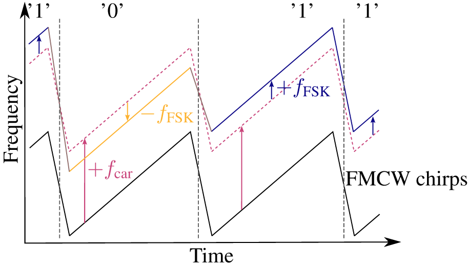
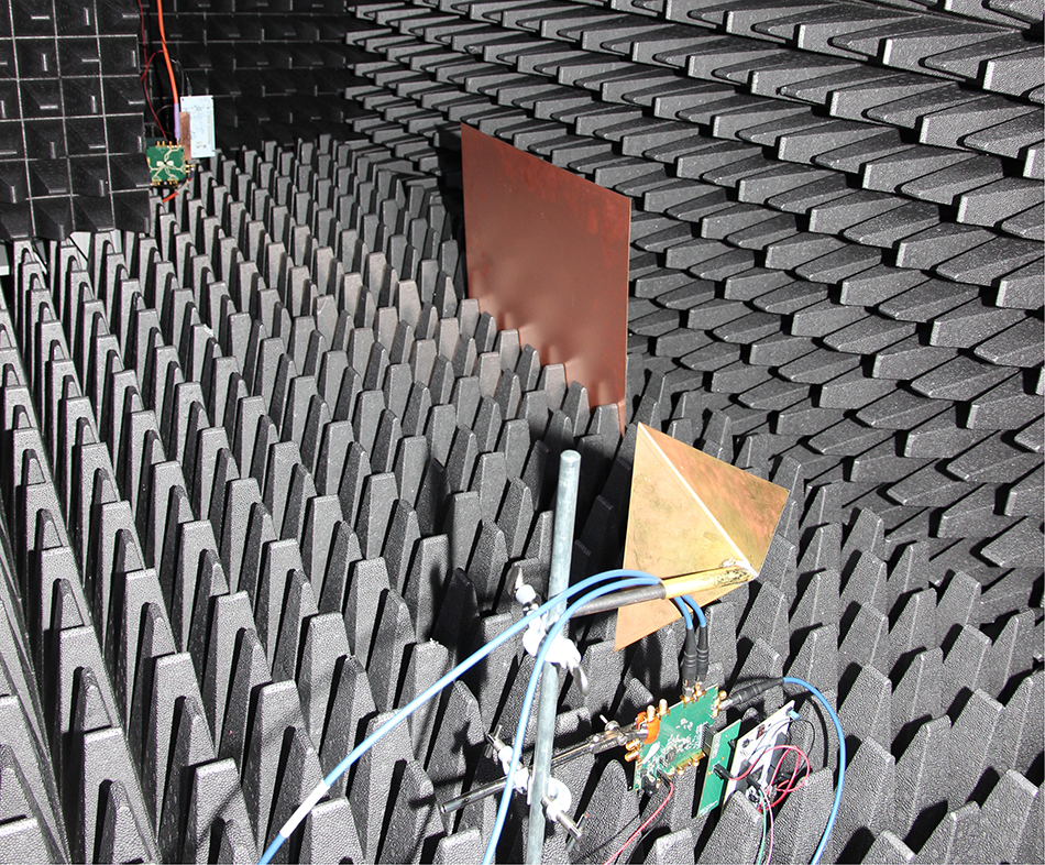
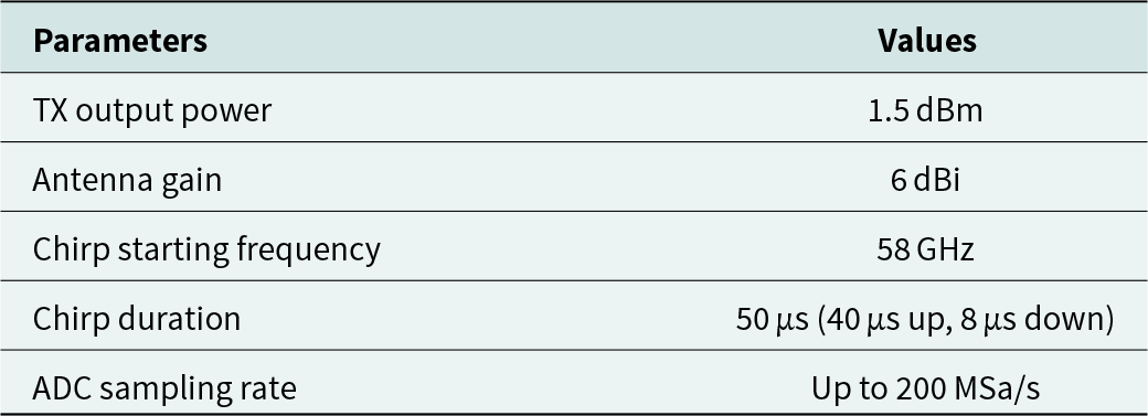
In this section, the hardware setup is explained in detail. A customized evaluation board presented in [Reference Faghih-Naini, Peters, Kurin, Erhardt, Reissland and Weigel14] is used as transceiver. It has in-phase and quadrature (IQ) data inputs in the baseband with a bandwidth of 2 GHz each. The input signals are mixed up to the RF band in the range of 57 GHz to 66 GHz in the transceiver chipset BGT60P and are transmitted via a patch antenna. For the measurements, one BGT60P custom board is used as transmitter and radar sensor. It is connected to the waveform generator 33600A from Keysight and the oscilloscope DSO91204A from Agilent. The waveform generator generates an FSK signal of a pseudo random bitstream with a defined deviation. The RX signal is measured. A second custom board, used as receiver, is connected to the oscilloscope UXR0254A from Keysight. The start of the chirp of the two boards is synchronized for the measurements via an external trigger signal. The two oscillators are also triggered with the same signal. The system parameters are summarized in Table 2. The system is visualized in Fig. 2, while in Fig. 3 the setup in an anechoic chamber is shown.
Schematic of the complete measurement setup.
Measurement setup in the anechoic chamber. Transmitter (in the back) and receiver (in the foreground) are communicating in the line of sight (LOS) and non-line of sight (NLOS) path via a copper panel.
System parameters
The BGT60P custom board includes the PLL LMX2491 from Texas Instruments, which is used to generate the FMCW chirps  $f_\text{FMCW}(t)$. A modulated chirp f(t) is created by mixing this signal with the FSK baseband signal $f_\text{com}(t)$. This is sent out via the patch antenna. It is important to synchronize the FSK signal with the chirps, because it ensures that f FSK stays constant during an upchirp. During the downchirp, the f com is changed if necessary to transmit the next symbol during the next upchirp.
Evaluation
Different measurements are performed to evaluate the functionality and parameters of this JCAS system. All measurements were performed in an anechoic chamber unless otherwise noted.
Chirp slope and duration
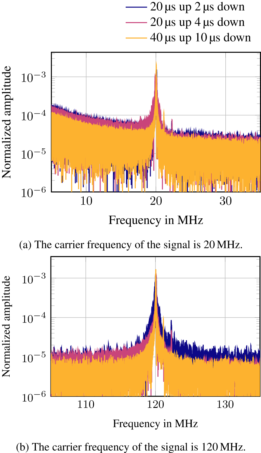
A PLL has a limited chirp rate. Shorter chirps mean a higher frequency change per time which leads to higher phase noise, a smaller signal amplitude, and a higher noise level in the PLL signal. This results in a higher noise floor in the resulting transmitted signal. A short downchirp leads to a noisy chirp start and to a higher noise floor. This behavior is analyzed, e.g., in [Reference Ergintav, Herzel, Kissinger and Ng15]. Figure 4(a) shows the results for the different chirp durations with a constant carrier frequency f car of 20 MHz and Fig. 4(b) shows the same for a carrier frequency of 120 MHz. In both measurements, a corner reflector target with an effective radar cross section of  $68\,\mathrm{m}^{-2}$ was present at a distance of 1.2 m. The dominant peak at the carrier frequency is the spillover between transmitter and receiver. Different chirp durations lead to different beat frequencies for the targets due to the slope of the frequency chirps, which explains the different frequencies of the target peaks, shown in Fig. 4(a) and (b). Due to the concept of using one chirp per bit, the chirp duration is proportional to the data rate. For the following measurements, the upchirp was chosen to be 40 μs and the downchirp 8 μs, because this combination leads to a low noise floor and a high signal-to-noise ratio (SNR), which can be seen in Fig. 4(a) and (b).
Frequency spectrum of three measurements with different chirp durations: 20 μs upchirp and 2 μs downchirp, 20 μs upchirp and 4 μs downchirp, 40 μs upchirp and 8 μs downchirp. A target was present at an distance of 1.2 m. (a) The carrier frequency of the signal is 20 MHz. (b) The carrier frequency of the signal is 120 MHz.
Carrier frequency selection of the FSK signal
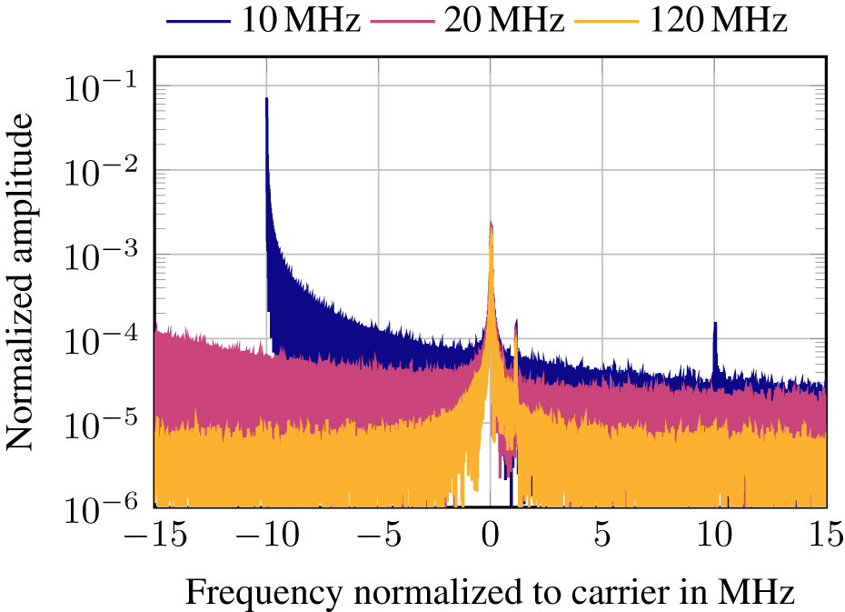
The choice of the FSK carrier frequency is very important. A higher carrier frequency means a lower noise floor of the signal, due to the reduced 1/f-noise. From this perspective, a higher carrier frequency is preferable but requires a higher ADC sampling rate. A further advantage is the greater unambiguous range of the radar signal, which is also limited by the carrier frequency. The maximum detectable distance of the target is f car because the targets are present in the upper sideband of the carrier frequency and its harmonics. To detect a target unambiguously, the beat frequency  $f_\text{b, max, compensated} \lt f_\text{com}(t)$ must be smaller than $f_\text{car}-f_\text{FSK}$. Figure 5 shows the different noise levels for a carrier frequency of 10 MHz, 20 MHz, and 120 MHz. Another aspect is the timing of the symbol transition of the FSK. In the setup used here, only the upchirp is evaluated and analyzed. If the symbol transition takes place within the evaluation signal, there are two possibilities to deal with it. No compensation of the frequency shift would lead to a peak width of $2f_\text{FSK}$, which lowers the resolution of the radar to because only targets with a difference in their beat frequencies greater than $2f_\text{FSK}$ can be distinguished. The better strategy is to compensate the frequency shift caused by the FSK. As the frequency change cannot be fulfilled instantaneously, this transition signal would add additional noise, which widens the target peak. In the proposed setup, the symbol transition during the downchirp avoids this downside. Also a higher f car means a smaller relative frequency transition so that the duration of the frequency change is shorter. This results in a radar signal with a lower SNR for short downchirp durations and less noise.
Comparison of the noise levels of three different carrier frequencies: 10 MHz, 20 MHz, and 120 MHz. A target was present at a distance of 1.2 m. This causes a frequency shift of 1 MHz.
Effect of the FSK modulation on the radar performance
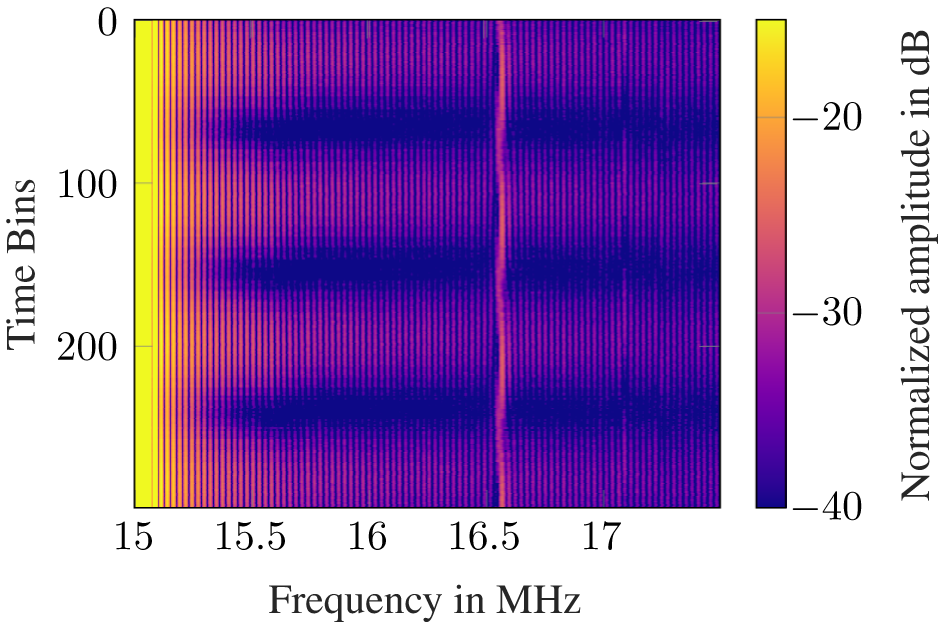
An FSK-modulated FMCW signal leads to a phase change at the beginning of each chirp. This can be seen in equation (9). Due to the FSK modulation frequencies and a fixed chirp duration, it is not possible to find a chirp period, which prevent a varying phase at each chirp start. This phenomenon leads to a slightly changing measured target distance, which is varying in time and needs to be compensated to achieve the best possible resolution. This effect is shown in Fig. 6, where the FMCW radar signal is modulated with a fixed frequency offset. In [Reference Iberle, Rippl and Walter16], this effect is also observed and examined.
Time-frequency map of beat signal modulated with a constant frequency offset of 15 MHz. At that frequency, the spillover of transmitter and receiver is visible. A target is detected at a distance of 1.9 m which leads to a frequency shift of 1.6 MHz. Due to the different phases of the modulated signal at the chirp start, the measured target distance is shifting slightly.
Modulating the FSK signal leads to detectable changes in the receiver signal. Without compensation, the measured beat frequency, which is proportional to the target distance, is shifting with the deviation of the FSK. In Fig. 7, the received signal modulated with a 2-FSK of a pseudo random bit sequence is shown. As the transmitted signals are known at the radar receiver, the frequency shifts can be determined and compensated in order to maintain the radar performance of the system. This is shown in equation (11).
Time-frequency map of beat signal from a target at a distance of 1.9 m measured at the radar receiver. The carrier is 15 MHz.
Data transmission with an FMCW radar
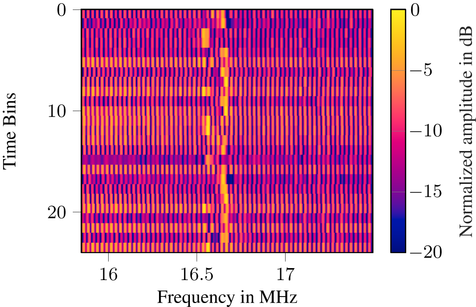
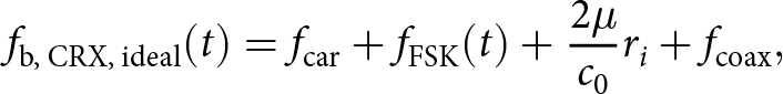
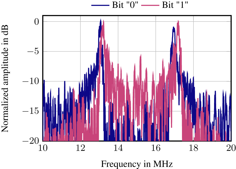
For the evaluation of transmitted data, a pseudo random bit sequence was sent out, detected, and then evaluated at the communication receiver side. A bit change leads to a spectral shift of the FSK frequency. In Fig. 8, the spectrum of two consecutively received chirps with a bitshift is shown. The chirp start on the receiver and transmitter board was synchronized by an external trigger signal. Due to the propagation time of the trigger signal in the coaxial cable, the received spectrum is shifted by this propagation time  $\tau_\text{coax}$, which means that the up-chirp of the receiver radar is started with a delay. More precisely, the beat frequency is
 \begin{equation}
f_\text{b, CRX, ideal}(t) = f_\text{car} + f_\text{FSK}(t)+\frac{2\mu}{c_0}r_{i}+f_\text{coax},
\end{equation}
\begin{equation}
f_\text{b, CRX, ideal}(t) = f_\text{car} + f_\text{FSK}(t)+\frac{2\mu}{c_0}r_{i}+f_\text{coax},
\end{equation} with the delay of the coaxial trigger wire  $\tau_\text{coax}$
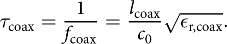 \begin{equation}
\tau_\text{coax} = \frac{1}{f_\text{coax}} = \frac{l_\text{coax} }{c_0}\sqrt{\epsilon_\text{r,coax}}.
\end{equation}
\begin{equation}
\tau_\text{coax} = \frac{1}{f_\text{coax}} = \frac{l_\text{coax} }{c_0}\sqrt{\epsilon_\text{r,coax}}.
\end{equation} f coax is the frequency offset due to the delayed start of the receiver ramp, l coax the length, and  $\epsilon_\text{r,coax}$ the permittivity of the coaxial trigger cable. This looks like a delay in the receiver signal. As the coaxial cable of a length of 15 m is used, it is more than five times as long as the shortest geometric distance between the two evaluation boards, which is 3 m. The frequency shift caused by the coaxial cable dominates. This leads to a peak shift in the lower MHz range in the received spectrum. Due to the oscillator tolerances due to, e.g., fabrication or temperature, the frequency of both chirps is not exactly the same, which causes frequency deviations during the measurements. This is summarized as $\Delta f_\text{PLL}(t)$. To be able to regain this, the offset must be smaller than f FSK
 \begin{equation}
f_\text{b, CRX, real}(t) = f_\text{car} + \Delta f_\text{PLL}(t) + f_\text{FSK}(t)+\frac{2\mu}{c_0}r_{i}+f_\text{coax}.
\end{equation}
\begin{equation}
f_\text{b, CRX, real}(t) = f_\text{car} + \Delta f_\text{PLL}(t) + f_\text{FSK}(t)+\frac{2\mu}{c_0}r_{i}+f_\text{coax}.
\end{equation}Due to the simplified synchronization and static setup of transmitter and receiver, the frequencies around the carrier at 15 MHz can now be extracted and detected in each chirp similar to a maximum search for target detection. The frequency of the maximum is mapped to the corresponding FSK symbol.
Spectrum of the beat signal of the in-phase received radar signal at the communication receiver at a distance of 1.9 m. The TX signal is an FMCW radar signal which was modulated by a 2-FSK.
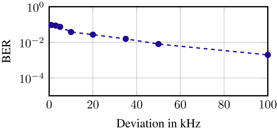
For the measurements, two different scenarios were evaluated: a scenario with a dominant line of sight (LOS) connection between transmitter and receiver and one with a non-line of sight (NLOS) connection. For the evaluation, about 1000 chirps were recorded and evaluated. The LOS distance was 1.92 m and the NLOS signal path had a distance of 2.34 m and a copper plate as the reflector. In the LOS setting, different FSK deviations were evaluated. The results in Fig. 9 show that an increased FSK frequency leads to a decreased bit error rate (BER). With a deviation of 100 kHz, a BER of 2 × 10⁻³ is achievable. Besides the LOS scenario, the received signal was also evaluated in an NLOS scenario with a BER of 4 × 10⁻³. A scenario with an LOS and an NLOS signal path could achieve a BER of 8 × 10⁻³. In a measurement scenario outside the anechoic chamber, the received signal in the distance of 2.75 m was evaluated and resulted in a BER of 4 × 10⁻². This shows that the communication signal evaluation works very well but its signal processing needs to be more complex in a real application scenario. At this point, reference is made to the existing literature on FSK demodulation methods.
Decrease of bit error rate (BER) with higher FSK deviation in the measurement distance of 1.9 m.
Measurement with moving targets
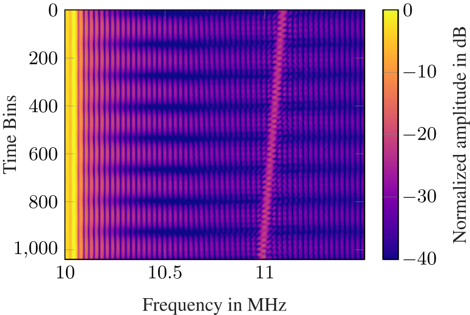
To prove the radar functionality with moving targets, dynamic measurements are performed. The challenge is to compensate the effects of the FSK modulation, especially the phase and frequency shift. A measurement with a moving target is performed and shown in Fig. 10. The target is moved toward the radar. The carrier is 10 MHz and an alternating bit sequence is modulated. For the signal evaluation, this needs to be corrected. Nevertheless, the FSK modulation of the signal increases the noise in the received signal, so that small targets cannot be detected.
Time-frequency map of beat signal of a moving target at the radar transceiver which is currently sending out alternating bit sequence. At 10 MHz, the carrier is visible due to the spillover between transmitter and receiver. The target starts at a distance of 1.2 m and moves continuously toward the radar sensor to a final distance of 1.1 m.
Discussion
In this work, a possibility to include a communication link into an FMCW radar is presented and evaluated. The approach is to modulate a whole frequency chirp with a specific frequency shift to transmit a bit. At the radar receiver, this frequency deviation is detected. It leads to a shifting beat frequency of a specific target. If not compensated, this seems like a shifting target. The frequency modulation leads to a varying chirp starting phase in the transmitted signal, which is attributable to the FSK modulation. In addition, this effect can be compensated because it is known at the transmitter and radar receiver side. Alternatively, a previously unmentioned approach is to generate the FSK signal with the PLL. This leads to a direct compensation of the FSK at the radar receiver side. At the communication receiver, the received signal is dechirped with an unmodulated chirp.
Different key design parameters were evaluated: chirp duration, carrier frequency of the FSK signal, and FSK deviation. The chirp duration must be chosen in order to allow the PLL to generate a phase and frequency stable chirp. Otherwise, the noise level increases. Therefore, less targets are visible as the SNR decreases. The chirp duration directly affects the data transmission rate. To increase it, the chirp duration must be kept short. The chirp duration in this system is 40 μs up and 8 μs down and leads to baud rates of 20.8 kbit/s, assuming a continuous repetition of the chirps. The higher the FSK carrier frequency, the lower the 1/f-noise of the signal. This comes at the expense of the need for an ADC with a higher sampling rate to meet the Nyquist–Shannon sampling theorem. The FSK signal shift due to a bit change must be done during the downchirp. In this setup, an FSK carrier frequency of 15 MHz was chosen. For the FSK deviation, different values were evaluated. A minimum deviation is necessary to be able to differentiate between bits. This is evaluated to be 50 kHz to achieve a BER of less than 10−2. A 2-FSK was evaluated in this work, but also a higher modulation order FSK M can be used. The effects stay the same for higher orders. The BER can be improved with more complex signal processing algorithms like equalization and forward error correction (FEC).
Limits of the system setup
In this work, the synchronization was realized with wires. For a practical system, a wireless synchronization needs to be implemented. This could be realized by using a common communication preamble and starting the modulated chirps and radar measurement after the synchronization. For further synchronization aspects, please refer to the literature [Reference Proakis and Salehi17]. A systemic limit of this JCAS system is the low data rate, due to its dependence of the chirps. One possibility to enhance the data rate is to implement a higher order FSK. With this higher deviation, the radar bandwidth needs to be limited, as the overall bandwidth stay constant  $const = BW + M f_\text{FSK}$. For a higher data rates, JCAS systems with other signal processing techniques must be used like orthogonal frequency division multiplex (OFDM) or code division multiple access (CDMA) based JCAS systems. This is, therefore, a compromise in terms of hardware complexity, as these high data rate systems require digital-to-analog converters and ADCs with sampling rates in the GSa/s range, which is not the case here. Furthermore, there is a not-negligible phase noise in the proposed system, which is attributed to the generation of the FSK signal. By generating the FSK directly in the PLL, the radar data are not influenced by the FSK modulation.
Comparison with other systems
In “State of the art of FMCW-based JCAS systems” section, various other communication systems are presented. They vary in the RF range with effect on the available bandwidth and range of the system. The ADC sampling rates are in the range of 7 MSa/s to 100 MSa/s. The proposed system uses a sampling rate of 200 MSa/s, which is higher than the sampling rate of the other approaches. However, the sampling rate can be reduced depending on the chosen carrier frequency of the FSK. This system employs a 2-FSK modulation which can be, e.g., increased to 16-FSK. This would increase the data rate to 83 kbit/s. Moghaddasi et al. use the TDMA technique, which allows an optimization of the communication performance but has the disadvantage of no radar measurements during the communication time slots. Schreiblhofer et al. [Reference Scheiblhofer, Feger, Haderer, Scheiblhofer and Stelzer8] can reach higher sampling rates due to the transmission of several bits during a chirp. This was also tested in the proposed system, but the system performed better with a higher modulation order instead of changing the bit during the frequency chirp. The reason for this is a noisy frequency change, which worsens the radar performance. Nevertheless, this proposed system offers a much greater bandwidth compared to all other ones. This leads to a very high radar resolution for measurements in centimeter range. Alabd et al. use a much shorter ramp of 30 μs upchirp and 5 μs downchirp. Furthermore, a part of the ramp cannot be used for the range estimation because of the frequency shift during the chirp. This also matters in the Doppler estimation. Due to these reasons, the method discussed in this work is preferable.
Conclusion
This paper shows a possible integration of a communication signal into existing radar systems. By modulating the FMCW radar chirps, bits can be transferred to a receiver without using new infrastructure or transmission hardware. This work verifies the measurement setup, in which the FMCW radar data were modulated by FSK to modulate the signal and transmit data. Measurements were performed to evaluate hardware aspects especially the impact of the behavior of the PLL with different setup parameters. The optimal carrier frequency is 15 MHz with a upchirp duration of 40 μs and the downchirp duration of 8 μs, respectively. The radar data were evaluated and the target could be detected clearly. The BER of the data transmission strongly depends on the FSK deviation, e.g., a deviation of 100 kHz results in a BER of 4 × 10⁻³ without advanced signal processing, like, e.g., equalization and FEC. This shows that the proposed JCAS system is suitable for data transmission in scenarios in which a data rate in kbit/s range is sufficient.
Acknowledgements
The authors would like to thank Infineon Technologies for providing the transceiver integrated circuit (IC) BGT60P and for supporting and funding this project.
Competing interests
The authors report no conflict of interest.

Samira Faghih-Naini received her B.Sc. degree in biomedical engineering and M.Sc. degree in biomedical and electrical engineering from Friedrich-Alexander-University Erlangen-Nürn-berg, Germany, in 2019 and 2021. In 2021, she joined the Institute for Electronics Engineering, Friedrich-Alexander-University Erlangen-Nürnberg, as a research assistant, where she is currently working toward the Ph.D. Her research interests are focused on signal processing and algorithms for joint communication and sensing systems and on RF communications and radar systems.
Michael Schneider received his B.Sc. degree in mechatronics engineering from the University of Applied Science Ulm, Germany, and his M.Sc. degree in mechatronics engineering from Friedrich-Alexander-University Erlangen-Nürnberg, Germany. He wrote his master thesis in 2023 on communication systems using FSK on an FMCW radar as a transmitter. After his Master in 2023, he returned to Ulm, where he joined the Microelectronics Research Group as a research assistant. Currently, he is working toward the PhD, focusing on the fusion of geophysical sensors.
Sebastian Peters received his B.Sc. and M.Sc. degree in electrical engineering from Friedrich-Alexander-University Erlangen-Nürnberg, Germany, in 2018 and 2021. In 2021, he joined the Institute for Electronics Engineering, Friedrich-Alexander-University Erlangen-Nürnberg, as a research assistant, where he is currently working toward his Ph.D. His research interests are focused on digital radar systems, including system architecture and radar signal processing.
Robert Weigel received all his academic degrees (Dipl.-Ing., Dr.-Ing., and Dr.-Ing. habil.) from the Munich University of Technology, Germany (TUM), where he has been appointed a Professor for RF Circuits and Systems in 1994. During 1996 to 2002, he has been Full Professor and Director of the Institute for Communications and Information Engineering at the Johannes Kepler University Linz, Austria (JKU). In Linz, in August 1999, he co-founded the company DICE, meanwhile split into an Infineon Technologies and an Apple company (in between it has been an Intel company). Since 2002, he is Full Professor and Director of the Institute for Electronics Engineering at the Friedrich-Alexander-University Erlangen-Nürnberg, Germany. There, in 2012, he co-founded the company eesy-ic, devoted to RF and mixed signal circuits, which now is a Bosch company. Dr. Weigel has been engaged in research and development of microwave theory and techniques, electronic circuits and systems, and communication and sensing systems.

Torsten Reissland completed his Bachelor’s degree in computer science and systems engineering at Ilmenau Technical University in 2013. He successfully completed his Master’s degree in electrical engineering at Friedrich-Alexander-University Erlangen-Nürnberg in March 2016. From May 2016 to July 2023, he worked as a research assistant at the Institute for Electronics Engineering (LTE) at FAU Erlangen-Nuremberg. From May 2022 to July 2023, he also headed the Circuits, Systems and Hardware Test group at this institute. In July 2023, he completed his doctorate with distinction. Since November 2023, he is working at the Chair of Electrical Smart City Systems, Freidrich-Alexander-Universität Erlangen-Nürnberg as group leader of the Digital Signal Processing and IC Design group.


 Open access