


Introduction
Metasurfaces [Reference Elineau, Loison, Méric, Gillard, Pagani, Mazé-Merceur and Pouliguen1, Reference Tretyakov2] have made possible a great quantity of electromagnetic wavefront manipulation types over the last decade [Reference Glybovski, Tretyakov, Belov, Kivshar and Simovski3]. In the field of radar, they spread their capabilities over various applications such as camouflaging techniques or radar cross-section (RCS) reduction [Reference Cacocciola, Ratni, Mielec, Mimoun and Burokur4, Reference Su, Yu, Yin, Guo, Xiao and Li5], backscattering enhancement [Reference Srour, Gillard, Méric and Seetharamdoo6], or anomalous reflection [Reference Yepes, Faenzi, Maci and Martini7, Reference Díaz-Rubio, Asadchy, Elsakka and Tretyakov8].
Historically, a very simple optical physics principle gave rise to phase gradient metasurfaces [Reference Yu, Genevet, Kats, Aieta, Tetienne, Capasso and Gaburro9]. The introduced generalized Snell's law allowed the design of anomalous reflectors of great simplicity, regarding either the underlying physics or the realization process. However, the inherent translation invariances of these structures raise spurious diffraction modes, which forced the community to find a more elaborated physical framework by incorporating Floquet theory to it. Periodic structures are very common in various physical domains, such as condensed matter physics where the Floquet–Bloch theory is already a very usual tool [Reference Yin, Galiffi and Alù10]. Applied to electromagnetic control, several research domains have emerged such as glide symmetric structures [Reference Quevedo-Teruel, Chen, Mesa, Fonseca and Valerio11], or metagratings [Reference Popov, Lepetit, Boust and Burokur12, Reference Ra'Di, Sounas and Alù13] where the objective is to channel the power from one Floquet mode into an other.
In the domain of anomalous reflection metasurfaces, it has been shown that it is difficult or even impossible to produce efficient passive reflective surfaces without considering non-local designs or polarization conversions [Reference Asadchy, Albooyeh, Tcvetkova, Díaz-Rubio, Ra'Di and Tretyakov14, Reference Kwon and Tretyakov15].
In this context, we propose an efficient optimization approach to shape the bistatic RCS of anomalous reflection metasurfaces. It relies on the method presented in [Reference Díaz-Rubio and Tretyakov16] which merges gradient metasurface approach and Floquet analysis. We build a fast predictive tool and use it in an optimization routine to design anomalous reflection metasurfaces with mitigated spurious diffraction modes.
The paper is organized as follows: section “Classical synthesis and its limitations” discusses the classical synthesis procedure and its limitations that are overcome by the use of Floquet analysis as presented in section “Floquet analysis.” An optimization process, taking advantage of the introduced considerations, is described in section “Metasurface optimization.” The application of the method is discussed and illustrated through specific study cases presented in section “Further examples.”
Classical synthesis and its limitations
Anomalous reflection configuration
The chosen anomalous reflection configuration is the one depicted in Fig. 1.
Anomalous reflection of a TM plane wave occurring in the Oyz plane, with an ideal or a discretized linear phase gradient lying in the Oxy plane.

A plane wave coming from the direction θ i impinges on a surface lying in a Oxy plane and is converted into an other plane wave reflected in the direction θ r. Both waves are transverse magnetic polarized (TM, H⊥Oyz). The anomalous reflection is made possible by the presence of a linearly varying reflection phase distribution along uy at the reflecting surface [Reference Yu, Genevet, Kats, Aieta, Tetienne, Capasso and Gaburro9].
A solution to synthesize such a phase gradient is to discretize it by using reflective cells. The discretization choice here is such that each gradient spatial period D y is covered with a same periodically distributed supercell, composed itself of three cells of size d. The phase law can be written in three equivalent ways to express the useful dimensions:

where k and λ are the wave number and wavelength at a given frequency f, θ i the direction of the incoming plane wave, and θ r the direction of the reflected one. For f = 8 GHz, θ i = 0°, and the anomalous reflection angle being set, for our example, to θ r = 60°, the two other dimensions are deduced: D y ≈ 43.3 mm and d ≈ 14.43 mm.
Phase law synthesis
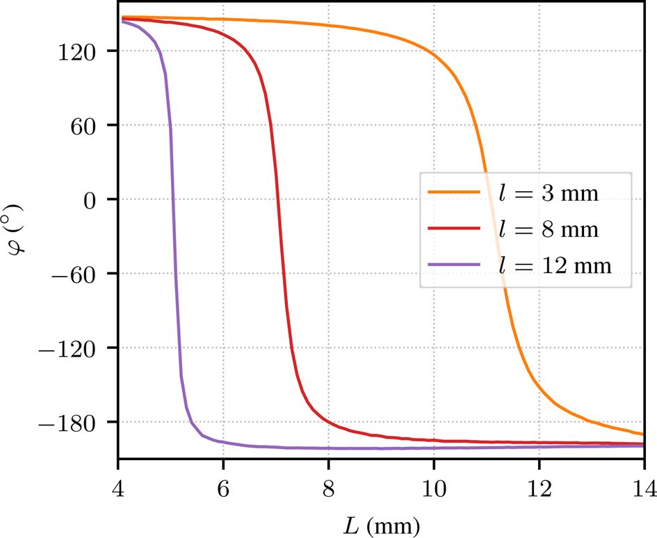
To produce the desired phase law, H shape patch cells studied in [Reference Haddad, Loison, Gillard, Harmouch and Jrad17] are used. The cells consist of a perfect electric conductor (PEC) patch on top of a dielectric substrate of relative permittivity ${\epsilon _r = 2.17}$ , backed by a PEC plane. Figure 2 presents the geometrical parameters of the cells as well as a phase response as a function of one parameter: the patch length L.
Variation of the phase response of the H cell versus L in infinite periodic environment for l = 3 mm. Fixed parameters are h = 1.6 mm, d = 14.43 mm, and W = 2 mm.

The three cells constituting the supercell must produce regularly spaced phase responses to create the linear phase variation. The needed geometrical parameters for each cell p ∈ {1, 2, 3}, highlighted on the trace of Fig. 2 by crosses, are listed in Table 1, as well as their phase response.
Geometrical parameters of the initial supercell

The supercell is then replicated nine times in the uy direction to produce an approximate array length of 10 λ. The array is studied in full-wave simulation using HFSS with absorbing boundary conditions along uy and a perfect magnetic conductor along ux to ensure infinite periodicity along the ux direction of TM polarization. The radiated fields are used to calculate a bistatic RCS pattern [Reference Knott, Shaeffer and Tuley18] that is shown in Fig. 3 in solid line.
Bistatic RCS for θ i = 0° of the initial surface compared to the analytical one used to design the surface.

The structure mainly radiates in the desired direction θ = 60°, but also shows noticeable radiation levels in two other main directions : θ = 0° and θ = −60°.
Limitations of the approach
During the synthesis procedure the surface is considered as an array of cells only characterized by their reflection coefficients ${\Gamma _p = e^{j \varphi _p}}$ , in such a way they are hosting a source field

E 0 being a unitary amplitude and φp taking only the three possible values presented in subsection “Phase law synthesis” with φp = φp+3. This source field can be converted into current densities and used in radiating integrals [Reference Balanis19] to calculate the field created by a vacuum-surrounded aperture hosting this source field. The obtained field is summed over all the 27 contributing cells to obtain a bistatic RCS diagram that is compared to the simulated one in Fig. 3.
This basic synthesis approach does not take into account the two parasitic radiation directions as only the main lobe at θ r = 60° is predicted by the analytical model. It is worth mentioning that, despite the simplicity of this approach, the main lobe level is well estimated by the analytical model, with only 0.4 dB difference with respect to the full-wave HFSS simulation.
Floquet analysis
Expected behavior
The periodicity of the array, obtained by the replication of the supercell, is the cause of the parasitic reflections. To understand this phenomenon, we study the structure with the help of Floquet analysis. The total three main radiation directions are predicted by Floquet analysis [Reference Bhattacharyya20]. They correspond to every m that provides real solutions to the equation

where

with k y0 and k ym the components along uy of the k0 and km wave vectors respectively. The first one is associated to the fundamental Floquet mode and the second one is associated to one harmonic Floquet mode. In the considered case, as the incoming and reflected waves propagate in the same medium, ${\lVert {\bf k}_0\rVert = \lVert {\bf k}_m\rVert = k}$ . Writing down k y0 = ksin (θ 0) and k ym = ksin (θ m) in (4) leads to

which is the generalized reflection law, written in (1), where θ m is the intended reflection direction after an illumination in the θ 0 direction. Performing anomalous reflection, with the help of the generalized reflection law, while setting the structure periodicity equal to the gradient periodicity is strictly equivalent to satisfy the m = 1 Floquet mode propagation condition. We also verify that in our case the modes m = −1 and m = 0 are propagative and correspond to the directions of the parasitic radiations observed in the previous section.
Usage of the Floquet-type simulation
In the light of the previous analysis, the anomalous reflection structure can be seen as a reflecting surface that has a conversion capability between the different propagative modes. To understand its behavior, the supercell can be simulated in a Floquet environment, as depicted in Fig. 4.
The supercell in Floquet-type simulation.

The supercell is infinitely replicated by the mean of master/slave pairs defined along the ux and uy directions. This allows to define a Floquet port that can be used to excite the structure.
Simulating such a structure gives access to a multimode coupling matrix whose elements are the S m,n complex parameters defined as

where E m is the complex field amplitude in a m reflected mode while the structure is studied under a n exciting mode of field amplitude E n. The parameters of interest in our example are the S m,0 because they correspond to an excitation with the n = 0 mode, which corresponds to an incidence of θ = 0°.
The S m,0 parameters of the simulated supercell used to create the initial array are reported in Table 2. The S −1,0 parameter is highlighted as it will be useful to be compared in the coming study of section “Metasurface optimization.”
S m,0 parameters of the initial supercell

It can already be noticed that the weights in decibels attributed to each mode roughly follow the same hierarchy than the corresponding lobe levels observed on the RCS diagram.
Incorporation of Sm,0 parameters in the model
As described in subsection “Limitations of the approach,” a radiated field can be obtained considering source fields on the surface. This time, the surface is not seen as an array of cells any more, but in its entirety, hosting three different source fields for the three possible values of m

Each source field is of unitary amplitude E 0 with a weighting S m,0, obtained from Table 2, and a phase variation corresponding to the considered Floquet mode. Source fields are again converted into current densities and used in radiation integrals. The three radiated fields are summed and give the bistatic RCS shown in Fig. 5 in dashed line.
Bistatic RCS for θ i = 0° of the initial surface compared to the analytical one using S m,0 simulation parameters.

The new source fields correctly reproduce the behavior of the simulated surface. Each main lobe level is well predicted, while the nine-supercell array is finite along uy, in contrast with Floquet-type simulation. This conclusion gives credit toward a representation of the surface with using only the S parameters associated to the supercell, thus avoiding the burdensome simulation type required to solve the whole structure. Taking advantage of this situation, we propose to perform S parameter optimizations, obtained with effortless simulations, that are expected to have a quantitative repercussion on the bistatic RCS of the complete structure.
Metasurface optimization
Process
The geometrical parameters of the cells (l p, L p) are chosen to be the optimization input variables and the objective is to minimize the level of the S −1,0 parameter. This definition is arbitrary and suits a particular application, the method is not restricted to it and can be used for other specifications. One may want to work for example with any S −n,n parameter, corresponding to backscattering that is of specific interest for numerous RCS applications. Indices m and n can also be larger than 1, if the supercell length is set accordingly. Our proposed approach can theoretically be extended to the optimization of such supercells with more higher-order Floquet modes. The formalism using S parameters remains basically the same and so does the power-transfer mechanism between propagative modes. Of course, the optimization problem gets more complex and more degrees of freedom might be needed to solve it. The cost function to be minimized is then

The aim is then to increase the difference between the lobe levels associated to the modes m = −1 and m = 1, avoiding the solutions where both of them are low, and without having a particular interest in handling the mode m = 0.
Starting a gradient type optimization process from the first supercell dimensions as an initial guess, the solution is expected to be close to the initial one, as it is already shaped from the phase gradient. In the same spirit, the cells used in the array are obviously in a different environment than the infinite periodic one used to obtain their phase response. The proposed optimization process can thus be seen as a way to better take into account the neighborhood of each cell, as the whole supercell is simulated.
Finally, based on our observations, we experience that some parameters are more sensitive than others. For example, as the L dimension is oriented along E, it shows a greater influence on S parameters than l. Hence, the critical dimension L can be first used in a rough analysis and l can be used afterwards for a fine tuning. A similar reasoning process can be applied to deal with sensitive cells, that are close to resonance, before others.
Results
Carrying the optimization process previously described leads to optimized S parameters presented in Table 3 and associated to the optimized dimensions presented in Table 4. New phase responses can be obtained by simulating the optimized cells (constituing the optimized supercell) in an infinite periodic environment, they are also presented in Table 4.
S m,0 parameters of the optimized supercell

Geometrical parameters of the optimized supercell

The $\vert S_{-1, 0} \vert$ level drops by a significant amount, while the two others are maintained. This already announces a more efficient mode conversion capability of the surface, for our specific application. It can also be seen that the new phase responses drifts out from the resonance region, where it is expected that they are more stable once in an array. This phenomena is illustrated in Fig. 6 where it can be seen that new phase responses now escape the φ = 0° region where the slope is greater. These geometrical variations are also very small, barely more than half a millimeter in most cases. This observation brings more confidence in the choice of the initial simple phase gradient, so it only needs a small adjustment to perform well.
Evolution of phase responses of the cells after an optimization process. The three new phase variations with L are computed the same way than the already presented one (in black), each one for the three optimized values of l.

New Es,m can now be computed using the optimized S m,0 parameters and then be used to calculate the expected RCS of the optimized array. This RCS is plotted in Fig. 7 where the initial calculated RCS is reminded.
Bistatic RCS for θ i = 0° of the optimized surface compared to the one of the initial surface. Both of them are obtained using their S m,0 associated simulation parameters.

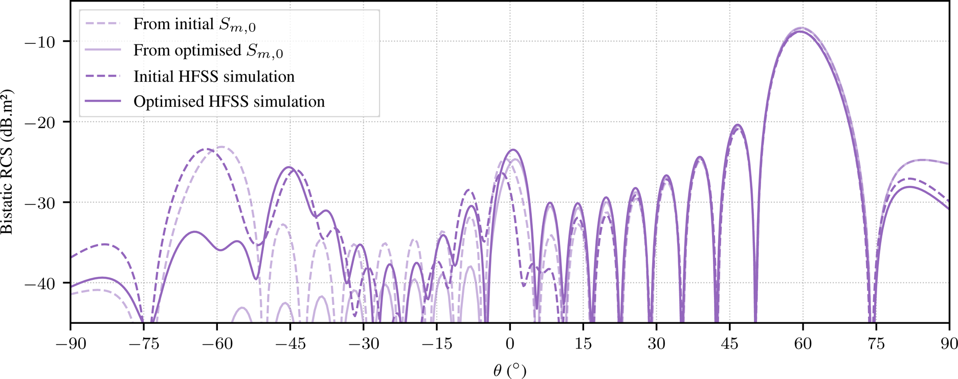
It must still be verified that the new array has the expected behavior with a rigorous simulation. The optimized geometry is put in the same full-wave environment than the initial one so they can be compared. Figure 8 shows the performances of the initial and optimized array as well as their predicted behavior by the use of S parameters. The global comparison is a way to check that the method is predictive as expected.
Bistatic RCS for θ i = 0° of the optimized surface compared to the one of the initial surface, in rigorous simulation and by using S parameters.

Indeed, the model correctly predicts both the initial and optimized structure behaviors. A 7.5 dB decrease of the parasitic lobe level is obtained while maintaining other radiation directions at a similar level.
Further examples
This section presents the optimization results of two others anomalously reflecting surface, where the initial l values are chosen to be 8 and 12 millimeters.
Case of l = 8 mm
Since the complete procedure has already been discussed, we propose here to only give concluding results and to comment them. Tables 5 and 6 give the geometrical variations and S m,0 parameter evolutions through the optimization process. Figure 9 shows the global bistatic RCS comparisons.
Bistatic RCS for θ i = 0° of the optimized surface compared to the one of the initial surface, in rigorous simulation and by using S parameters. Case l = 8 mm.

Evolution of the supercell dimensions during the optimization process

Case l = 8 mm.
Evolution of the supercell S m,0 parameters during the optimization process

Case l = 8 mm.
The $\vert S_{-1, 0} \vert$ level drastically decreases, but one should carefully keep in mind that the initial level was lower compared to the previous case. In contrast, the $\vert S_{0, 0} \vert$
 level raises as the optimization process does not handle it. Geometrical variations of the supercell are smaller than in the first l = 3 mm case and so it is for phase response evolution. The largest geometrical variation for this case is 4% of the initial cell size and is in contrast about 32% for the first presented case. The optimized array performance is greatly improved, by an attenuation of 15 dB on the parasitic lobe level. Nevertheless, the model is less quantitative in this region where the RCS quantities are very low on the decibel scale.
Case of l = 12 mm
In the same way, concluding results for another case where the starting l value for optimization is 12 mm can be found in Tables 7 and 8 and in Fig. 10.
Bistatic RCS for θ i = 0° of the optimized surface compared to the one of the initial surface, in rigorous simulation and by using S parameters. Case l = 12 mm.
Evolution of the supercell dimensions during the optimization process

Case l = 12 mm.
Evolution of the supercell S m,0 parameters during the optimization process

Case l = 12 mm.
The $\vert S_{-1, 0} \vert$ value drops by a great amount as well and the expected RCS diagram shows very low lobe levels for the θ = −60° direction. Even if the bistatic RCS diagram shows a 10 dB reduction performance in the θ = −60° direction, the model is less accurate in this angular region, where RCS values are lower. Cell geometry variations are even smaller in this case, actually going under manufacturing precision. Still corroborating the viability of the used technique, this last example could however be unrealistic for practical implementation.
Global results commentary
The three pairs of presented structures exhibit a radiation peak around the −45° area. They also share a lot of their properties, such as array lengths, substrate thickness, cells, and patch shapes for example. It surely goes beyond the scope of the model presented in this publication, but exploring the shared properties of the surfaces should lead to discriminate the origin of this particular radiation.
All the presented structures use the same patch geometry and same degrees of freedom for optimization, but converge to different optimal values. This obviously proves that at least two of them are not global optimums. This is not a surprising conclusion since they all use an initial guess from which it is intended to not deviate too much. This is a way to keep the computing resources needed for optimization very low.
Figure 11 compares phase variations of the cells used in the three initial cases, with respect to L. Globally, the absolute value of the slope at resonance grows as l increases. This gives an explanation about the smaller geometrical variations observed through the three cases, as l is larger for each case.
Phase response, in infinite periodic environment, of the H-shaped patch cells versus L for the three studied cases.
The case for which l = 3 mm shows a smoothly varying phase response with L, but the phase range being in greater L region the resulting cells are wider and then closer to their neighbor in array environment. This could expose them more to coupling effects. In a complementary way, the case for which l = 12 mm shows really sensitive phase response regarding L but giving huddled and then isolated cells once in an array. The Floquet-type simulation takes into account the coupling effects between cells in a supercell and between supercells in infinite array. Nevertheless, we may expect slight deviations in the case of a realistic finite array as we have here. The case for which l = 8 mm then results in a good trade-off for supercell stability. It is actually the case where the optimized array shows the best performance in attenuating the level of the S −1,0 corresponding lobe.
Finally, applying the process to several cases showed the robustness of the proposed method while giving some synthesis advices for this kind of structures.
Conclusion
In this publication we proposed a method that takes advantage of translation invariance usually found in metasurfaces, by using results of Floquet analysis and simulation. After showing the limitations of the classical approach we chose to exploit S m,n simulation parameters to better represent the physical behavior of the structure. After being incorporated in an analytical model, these parameters were manipulated in an optimization process. One first optimization process proved the efficiency of the method and two other cases showed that the method is repeatable, and quantitative with respect to the predicted RCS levels, especially in regions with large RCS returns. In all cases, the proposed optimization method drastically reduced the targeted parasitic radiation. The last discussions also raised some advices, limitations, and tracks for the synthesis of this kind of structure. As the method was tested in simulation environments, future work will focus on experimental validations. In particular, the predicted RCS gains will be verified in the context of a practical implementation with limited manufacturing precision.
Acknowledgements
This work is funded by the French organizations Commissariat á l’Énergie Atomique (CEA) and Agence Innovation Défense (AID).
Conflict of interest
None.
 Matthieu Elineau is currently pursuing Ph.D. at the National Institute of Applied Sciences (INSA) of Rennes, France. His research activities with the Institut d’Électronique et des Technologies du numérique (IETR; Rennes, France) and the CEA (Le Barp, France) are on the use of metasurfaces for radar applications.
 Renaud Loison is a professor at the National Institute of Applied Sciences (INSA), Rennes, France. He carries out his research activity at the Institut d’Électronique et des Technologies du numérique (IETR) and works on reflectarrays, metasurfaces, and more generally on periodic and quasi-periodic surfaces.
 Stéphane Méric (M’08) simultaneously graduated in 1991 from the National Institute of Applied Sciences (INSA), Rennes, France, with an electrical engineer diploma and from the University of Rennes 1, with an M.S. in signal processing and telecommunications. He obtained Ph.D. (1996) in electronics from INSA and Habilitation á Diriger des Recherches (HDR) from the University of Rennes 1 in 2016. Since 2000, he is an assistant professor at INSA, and in 2005, he joined the SAPHIR team (IETR–CNRS UMR 6164, Rennes). He was interested in using SAR data in radargrammetric applications. Furthermore, he is currently working on radar system (CW, FMCW) dedicated to specific SAR applications (radar imaging in motorway context, remote sensing, MIMO configuration, and passive radar imaging) and remote-sensing applications. His education activities are about analog electronics, signal processing, radar and radar imaging, and electromagnetic diffraction.
 Raphaël Gillard obtained Ph.D. in 1992. He first worked as a research engineer in a company, developing full-wave simulators for microwave circuits and antennas. He joined the National Institute of Applied Sciences (INSA), Rennes, France, in 1993. Since 2001, he has been a full professor with the INSA. His main research interests are computational electromagnetics, reflectarrays, array antennas, dielectric resonator antennas, and periodic structures.
 Pascal Pagani obtained M.Sc. in communication systems and signal processing from the University of Bristol, UK, in 2002, Ph.D. in electronics from the National Institute of Applied Sciences (INSA), Rennes, France, in 2005, and habilitation degree from the Université de Bretagne Occidentale, Brest, France in 2016. From 2002 to 2012, he conducted research with Orange Labs in the fields of in-home high data rate communications. He was a recipient of the Grand Prix Général Ferrié in 2013 for his research on transmission over power lines. From 2012 to 2016, he was an associate professor at the graduate engineering school Telecom Bretagne, Brest, France, where he worked on long-haul radio wave propagation and advanced wireline communications. He is currently with the Commissariat á l'Energie Atomique, Le Barp, France, where he specializes in the field of wave-matter interaction in the context of radar, in particular for RCS characterization and reduction.
 Geneviève Mazé-Merceur obtained Dipl. Eng., D.E.A., and Ph.D. from École Nationale Supérieure d’Électronique et de Radioélectricité de Grenoble, France, in 1988, 1988, and 1991, respectively. She received Habilitation á Diriger des Recherches from Université de Savoie, France, in 1999. Since 1991, she has been with the Commissariat á l’Énergie Atomique, Le Barp, France. Her research interests include the modeling of electromagnetic wave problems, microwave characterization of materials, and radar cross-section measurements.
 Philippe Pouliguen obtained M.S. in signal processing and telecommunications, Ph.D. in electronics, and Habilitation á Diriger des Recherchesé from the University of Rennes 1, Rennes, France, in 1986, 1990, and 2000, respectively. In 1990, he joined the Direction Générale de l'Armement (DGA), DGA Information Superiority (DGA/IS), Bruz, France, where he was a senior expert in electromagnetic radiation and radar signatures. He was also in charge of the Expertise and ElectoMagnetism Computation (EMC) Laboratory, DGA/IS. From 2009 to 2018, he was the head of the “acoustic and radio-electric waves” scientific domain at DGA, Paris, France. Since 2018, he has been the innovation manager of the “acoustic and radio-electric waves” domain at the Agence Innovation Défense (AID), Paris. His research interests include electromagnetic scattering and diffraction, radar cross-section (RCS) measurement and modeling, asymptotic high-frequency methods, radar signal processing and analysis, antenna scattering problems, and electronic bandgap materials.


 Open access