


INTRODUCTION
Pressurised meltwater beneath glaciers and ice sheets is believed to have a major effect on ice sheet dynamics, as well as deformation and sedimentary processes (e.g., Boulton et al., Reference Boulton, Dent and Morris1974; Boulton and Caban, Reference Boulton and Caban1995; Hiemstra and van der Meer, Reference Hiemstra and van der Meer1997; Rijsdijk et al., Reference Rijsdijk, Owen, Warren, McCarroll and van der Meer1999; Phillips and Auton, Reference Phillips and Auton2000; Boulton et al., Reference Boulton, Dobbie and Zatsepin2001; Khatwa and Tulaczyk, Reference Khatwa and Tulaczyk2001; Baroni and Fasano, Reference Baroni and Fasano2006; Kjær et al., Reference Kjær, Larsen, van der Meer, Ingólfsson, Krüger, Benediktsson, Knudsen and Schomacker2006; Phillips et al., Reference Phillips, Merritt, Auton and Golledge2007; van der Meer et al., Reference van der Meer, Kjær, Krüger, Rabassa and Kilfeather2009; Sole et al., Reference Sole, Mair, Nienow, Bartholomew, King, Burke and Joughin2011; Moon et al., Reference Moon, Joughin, Smith, Broeke, Berg, Noël and Usher2014). Increased porewater pressures can cause accelerated flow (basal sliding) attributable to decoupling between the ice and its bed, as well as enhanced sediment remobilisation and deformation because of reduced sediment shear strength (e.g., Piotrowski and Tulaczyk, Reference Piotrowski and Tulaczyk1999; Boulton et al., Reference Boulton, Dobbie and Zatsepin2001; Fischer and Clarke, Reference Fischer and Clarke2001; Phillips et al., Reference Phillips, Everest and Reeves2012, Reference Phillips, Cotterill, Johnson, Crombie, James, Carr and Ruiter2018; Evans, Reference Evans2018). Deformation influenced by elevated water pressures can either result in the pervasive weakening of the sediment pile or be focused along discreet, water-lubricated detachments (Alley, Reference Alley1989; Fischer and Clarke, Reference Fischer and Clarke2001; Kjær et al., Reference Kjær, Larsen, van der Meer, Ingólfsson, Krüger, Benediktsson, Knudsen and Schomacker2006; Phillips and Merritt, Reference Phillips and Merritt2008). The development of such low-friction detachments/décollements is thought to have a considerable effect on the style and magnitude of glaciotectonics facilitating the transport of large thrust blocks of sediment and/or bedrock (Aber and Ber, Reference Aber and Ber2007; Phillips and Merritt, Reference Phillips and Merritt2008; Burke et al., Reference Burke, Phillips, Lee and Wilkinson2009; Rüther et al., Reference Rüther, Andreassen and Spagnolo2013; Vaughan-Hirsch et al., Reference Vaughan-Hirsch, Phillips, Lee and Hart2013) leading to the construction of large thrust-block or composite moraines (Croot, Reference Croot1987; Bennett, Reference Bennett2001; Pedersen, Reference Pedersen2005; Aber and Ber, Reference Aber and Ber2007; Benediktsson et al., Reference Benediktsson, Möller, Ingólfsson, van der Meer, Kjær and Krüger2008; Phillips et al., Reference Phillips, Everest, Evans, Finlayson, Ewertowski, Guild and Jones2017; Vaughan-Hirsch and Phillips, Reference Vaughan-Hirsch and Phillips2017; Sigfúsdóttir et al., Reference Sigfúsdóttir, Benediktsson and Phillips2018).
It has been argued that the presence of a well-developed permafrost layer in front of the advancing glacier above the detachments can aid in the construction of large thrust-block moraines as it allows stress to be transmitted far into the forefield of the glacier (Aber et al., Reference Aber, Croot and Fenton1989; Evans and England, Reference Evans and England1991; Boulton and Caban, Reference Boulton and Caban1995; Boulton et al., Reference Boulton, Van der Meer, Beets, Hart and Ruegg1999; Bennett, Reference Bennett2001, or the base of the frozen layer acts as a focus for detachment above which deformation occurs (Burke et al., Reference Burke, Phillips, Lee and Wilkinson2009; Benediktsson et al., Reference Benediktsson, Schomacker, Johnson, Geiger, Ingólfsson and Guðmundsdóttir2015).
Furthermore, it has been argued that the freezing of sediments and/or bedrock to the base of the glacier is important for transportation of detached, largely intact thrust blocks (or rafts/megablocks) (Clayton and Moran, Reference Clayton, Moran and Coates1974; Banham, Reference Banham1975; Bluemle and Clayton, Reference Bluemle and Clayton1984; Ruszczynska-Szenajch, Reference Ruszczynska-Szenajch1987; Aber, Reference Aber and Croot1988). However, it has increasingly been shown that overpressurised water within the substratum can cause the detachment and emplacement of large, unconsolidated thrust blocks without the ground being frozen (Moran et al., Reference Moran, Clayton, Hooke, Fenton and Andriashek1980; van der Wateren, Reference van der Wateren1985; Broster and Seaman, Reference Broster and Seaman1991; Aber and Ber, Reference Aber and Ber2007; Benediktsson et al., Reference Benediktsson, Möller, Ingólfsson, van der Meer, Kjær and Krüger2008; Phillips and Merritt, Reference Phillips and Merritt2008; Benn and Evans, Reference Benn and Evans2010; Phillips et al., Reference Phillips, Everest, Evans, Finlayson, Ewertowski, Guild and Jones2017; Vaughan-Hirsch and Phillips, Reference Vaughan-Hirsch and Phillips2017). Such sediment blocks can be transported over long distances; for example, thrust-bound rafts of glaciomarine sediments in Clava, Scotland, were shown to have been transported subglacially at least 50 km from their origin aided by fluid flow along the décollement surfaces (Phillips and Merritt, Reference Phillips and Merritt2008).
However, a detailed understanding of the processes occurring along the major detachments formed during glaciotectonism has yet to be established, including how input of pressurised water controls variations in deformation styles and how that relates to the evolution of a large thrust-block complexes. This article presents the results of a micro- and macroscale investigation of the detachments developed within two thrust-block moraines in Melasveit, western Iceland. As these moraines were formed in a submarine environment, it can be assumed that the sediments were unfrozen at the time of deformation. This study uses micromorphology to investigate the changing style of deformation during the transport and emplacement of the thrust blocks. The factors controlling the style and magnitude of deformation are discussed—in particular, the effect of the introduction of pressurised water along the bounding thrusts during this process. The results of this study are presented in a conceptual sequential model and discussed in the wider context of the interrelationships between glacier dynamics, submarginal hydrology, and glaciotectonics.
Location of the study area and its geologic context
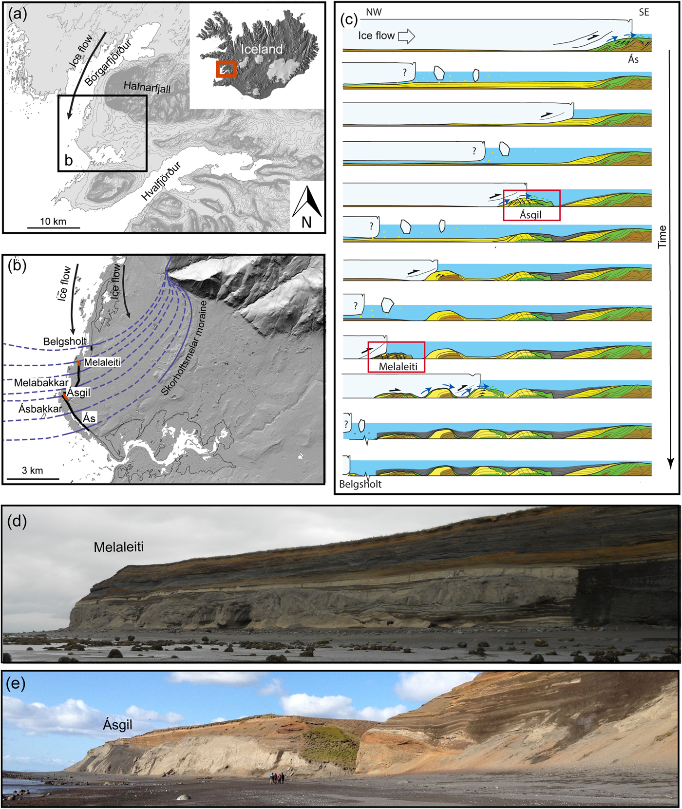
The Melasveit district of western Iceland is a coastal lowland area situated between the fjords of Borgarfjörður and Hvalfjörður (Fig. 1a). The geology of the area is dominated by a >30-m-thick sequence of Late Weichselian to Holocene glaciomarine to deltaic sediments overlying a striated bedrock surface (Ingólfsson, Reference Ingólfsson1987, Reference Ingólfsson1988; Sigfúsdóttir et al., Reference Sigfúsdóttir, Benediktsson and Phillips2018). The bedrock in the Melasveit area is mainly composed of Neogene basaltic lava flows, which are thought to have largely originated from the extinct Hafnarfjall-Skarðsheiði central volcano located to the northeast (Franzson, Reference Franzson1978).
(a) The location of the Melasveit study area (black box) in western Iceland. The arrow indicates the direction of ice flow into the area during the Late Weichselian. (b) A digital elevation model (Arctic DEM) of Melasveit. Thin black line represents the present coastline, and the thick black lines denote the Melabakkar-Ásbakkar coastal cliffs. The red lines indicate the location of the Melaleiti and Ásgil thrust-block moraines in the cliffs. The curved, solid blue lines indicate the extent of the Late Weichselian glacier from the north based on the configuration of the Skorholtsmelar end moraine and the location of the buried moraines in the coastal sections. The dashed lines are the interpreted lateral extent of the ice margins (Sigfúsdóttir et al., Reference Sigfúsdóttir, Benediktsson and Phillips2018). (c) A conceptual sequential model showing the formation of the glaciotectonic moraines that are exposed in the Melabakkar-Ásbakkar and Belgsholt coastal cliffs. Each moraine inside (to the left of) the outermost moraine (Ás-Skorholtsmelar) marks a readvance of the glacier during an active retreat. The red boxes highlight the formations of the Ásgil and Melaleiti moraines. Black arrows indicate displacement; blue arrows, water flow; brown, preexisting glaciomarine sediments (unit A); green, meltwater deposits (units B and F); yellow, syntectonic glaciomarine sediments (units C–E); and grey, posttectonic, undeformed glaciomarine sediment (unit G) (Sigfúsdóttir et al. Reference Sigfúsdóttir, Benediktsson and Phillips2018). (d) An overview of the coastal section at Melaleiti. (e) An overview of the coastal section at Ásgil. The moraine is exposed to the north (left side) of the ravine, whereas associated submarine fan and overlying glaciomarine sediments are exposed on the southern side (right side). (For interpretation of the references to colour in this figure legend, the reader is referred to the web version of this article.)
The Melasveit district was covered by ice during the Last Glacial Maximum (LGM) and was subsequently deglaciated rapidly between ca. 15 and 14.7 cal ka BP, following the collapse of the marine-based western sector of the Icelandic Ice Sheet (Ingólfsson, Reference Ingólfsson1987, Reference Ingólfsson1988; Syvitski et al., Reference Syvitski, Jennings and Andrews1999; Jennings et al., Reference Jennings, Syvitski, Gerson, Grönvold, Geirsdóttir, Hardardóttir, Andrews and Hagen2000; Norðdahl et al., Reference Norddahl, Ingólfsson, Pétursson and Hallsdóttir2008; Ingólfsson et al., Reference Ingólfsson, Norddahl, Schomacker, Schomacker, Krüger and Kjær2010; Norðdahl and Ingólfsson, Reference Norddahl and Ingólfsson2015; Patton et al., Reference Patton, Hubbard, Bradwell and Schomacker2017). As a result, the relative sea level in the region was up to at least 125–150 m higher than present (Ingólfsson and Norðdahl, Reference Ingólfsson and Norddahl2001; Norðdahl and Ingólfsson, Reference Norddahl and Ingólfsson2015). Consequently, this low-lying area remained below sea level throughout most of the Late Weichselian leading to the deposition of a thick sequence of glaciomarine sediments.
The relative sea level fluctuated considerably during this time, reaching a maximum during a phase of renewed glacier expansion in both the Younger Dryas (ca. 12.9–11.7 cal ka BP) when the relative sea level was about 60–80 m higher than present and again in the Early Preboreal (ca. 11.7–10.1 cal ka BP) (Ingólfsson, Reference Ingólfsson1988; Norðdahl et al., Reference Norddahl, Ingólfsson, Pétursson and Hallsdóttir2008; Ingólfsson et al., Reference Ingólfsson, Norddahl, Schomacker, Schomacker, Krüger and Kjær2010).
After the initial deglaciation of Melasveit during the Bølling chronozone, a large outlet glacier in Borgarfjörður advanced from the north while the area was still isostatically depressed and culminated in the construction of the Skorholtsmelar end moraine (Fig. 1b) (Ingólfsson, Reference Ingólfsson1987, Reference Ingólfsson1988; Ingólfsson et al., Reference Ingólfsson, Norddahl, Schomacker, Schomacker, Krüger and Kjær2010; Sigfúsdóttir et al., Reference Sigfúsdóttir, Benediktsson and Phillips2018). This also resulted in large-scale glaciotectonic deformation of the glaciomarine sediments exposed in the greater than 5-km-long and up to 30-m-high coastal cliffs of Melabakkar-Ásbakkar and a smaller coastal section at Belgsholt (see Fig. 1b and c) (Ingólfsson, Reference Ingólfsson1987, Reference Ingólfsson1988; Hart, Reference Hart1994; Hart and Roberts, Reference Hart and Roberts1994; Sigfúsdóttir et al., Reference Sigfúsdóttir, Benediktsson and Phillips2018). Building on the pioneering stratigraphic framework of Ingólfsson (Reference Ingólfsson1987, Reference Ingólfsson1988), a detailed investigation of the stratigraphy and glaciotectonic architecture of these coastal sections by Sigfúsdóttir et al. (Reference Sigfúsdóttir, Benediktsson and Phillips2018) showed that a series of at least six buried ice-marginal/proglacial moraines is recorded in the cliffs (Fig. 1c). The internal structure of the moraines records large-scale glaciotectonic thrusting and folding of glaciomarine sediments, usually interleaved with penecontemporaneous, ice-marginal sands and gravels (Fig. 1c). The southernmost and largest moraine, called Ás in the cliffs, is more than 1.5 km wide and is correlated with the Skorholtsmelar moraine ridge a few kilometres farther inland and marks the maximum position of the post-LGM advance in the area (Fig. 1b). Sigfúsdóttir et al. (Reference Sigfúsdóttir, Benediktsson and Phillips2018) suggested that the moraines north of Skorholtsmelar-Ás were formed as the glacier readvanced several times during an overall active retreat. Glaciomarine sediments were continuously being deposited and largely deformed during subsequent advances of the glacier. In general, the moraines become younger toward the north, the Belgsholt moraine being the youngest in the series (Sigfúsdóttir et al. Reference Sigfúsdóttir, Benediktsson and Phillips2018; Fig. 1b and c).
Based on this investigation and previously published radiocarbon ages from the glaciotectonised sediments (Ingólfsson, Reference Ingólfsson1987, Reference Ingólfsson1988; Norðdahl and Ingólfsson, Reference Norddahl and Ingólfsson2015), Sigfúsdóttir et al. Reference Sigfúsdóttir, Benediktsson and Phillips2018 concluded that the readvances and subsequent active retreat of the Borgarfjörður glacier occurred after ca. 13.4 cal ka BP. This suggests that the moraines were formed during the Younger Dryas (Sigfúsdóttir et al., Reference Sigfúsdóttir, Benediktsson and Phillips2018). As the glacier retreated, the sedimentary basins between the moraines were progressively infilled by well-bedded, undeformed glaciomarine sediments (Fig. 1c). The entire glaciogenic sequence is unconformably overlain by littoral sands and gravels of early Holocene age (Ingólfsson, Reference Ingólfsson1987, Reference Ingólfsson1988).
The present study focuses on two of the moraines exposed in Melabakkar-Ásbakkar: Melaleiti and Ásgil (Fig. 1b–e). Both of these moraines show a relatively simple structural architecture with easily identified and accessible basal thrusts, thus allowing the deformation history to be confidently reconstructed. These moraines can be classified as thrust-block moraines (see Benn and Evans Reference Benn and Evans2010 and references therein) and are characterised by a number of stacked, low-angle/subhorizontal thrust blocks (nappes), which show little evidence of large-scale folding. The geometry of the moraines is typical for glaciotectonic landforms formed by low-frictional sliding, supported by the relatively rigid nature of the thrust-block deposits (van der Wateren, Reference van der Wateren1995; Huddart and Hambrey, Reference Huddart and Hambrey1996; Boulton et al., Reference Boulton, Van der Meer, Beets, Hart and Ruegg1999; Bennett, Reference Bennett2001). Based on this macro- to microscale study, a model is proposed that aims to link the microscale processes recorded along the bases of these two thrust blocks to each phase in the structural evolution of the thrust-block moraines.
METHODS
The large-scale glaciotectonics and stratigraphy of the Melabakkar-Ásbakkar cliff section have previously been described by Sigfúsdóttir et al. (Reference Sigfúsdóttir, Benediktsson and Phillips2018), who divided this variably deformed glaciomarine sequence into eight informal sedimentary units (A–H); the same tectonostratigraphic framework has been adopted here. The detailed analysis of the macro- and microscale deformation structures associated with the emplacement of the thrust-bound blocks of glaciomarine sediments into the moraines is focused on the Melaleiti and Ásgil sections (Fig. 1b–e). Particular emphasis is placed on understanding the nature of the deformation associated with the prominent thrust planes, which form the basal detachments to the allochthonous blocks.
A total of 16 orientated samples (Ásgil 1 to 10 from Ásgil and Mel 11 to 16 from Melaleiti) were collected from within these basal detachments for detailed micromorphological and microstructural analysis. Each sample was collected using a 10 × 10 × 5 cm aluminium Kubiena tin. The position of the sample within the thrust zone, its orientation relative to magnetic north, depth, and way up were recorded. The samples were taken from different parts of the basal detachment in order to provide detailed information on the style and intensity of deformation within these glaciotectonic contacts, as well as to examine the role played by pressurised water during the transport and emplacement of the thrust blocks. Each sample was sealed in two plastic bags and kept in cold storage prior to sample preparation at the British Geological Survey's thin section laboratory (Keyworth, Nottingham, UK). Sample preparation involves the replacement of porewater by acetone, which is then progressively replaced by a resin and allowed to cure. Large format orientated thin sections were taken from the centre of each of the prepared samples, thus avoiding artefacts associated with sample collection. Each large format thin section was cut orthogonal to the stratification/bedding within the sediment and parallel to the main ice movement direction in the study area. The thin sections were examined using a standard petrologic microscope and stereomicroscope allowing the detailed study of the microstructures at a range of magnifications. The terminology used to describe the various microtextures developed within these sediments in general follows that proposed by van der Meer (Reference van der Meer1987, Reference van der Meer1993) and Menzies (Reference Menzies2000) with modifications. Detailed maps of the range of sediments and microstructures present within the thin sections were obtained using the methodology of Phillips et al. (Reference Phillips, van der Meer and Ferguson2010) (also see Phillips et al., Reference Phillips, Everest and Reeves2012; Neudorf et al., Reference Neudorf, Brennand and Lian2013; Vaughan-Hirsch et al., Reference Vaughan-Hirsch, Phillips, Lee and Hart2013). Because of the large number of thin sections analysed, microstructural analysis of the 12 most representative thin sections, which illustrate the complete range of structural relationships, are included in this article. However, interpretive diagrams and high-resolution scans of the remaining four thin sections are included as Supplementary Material.
RESULTS
The Ásgil thrust-block moraine
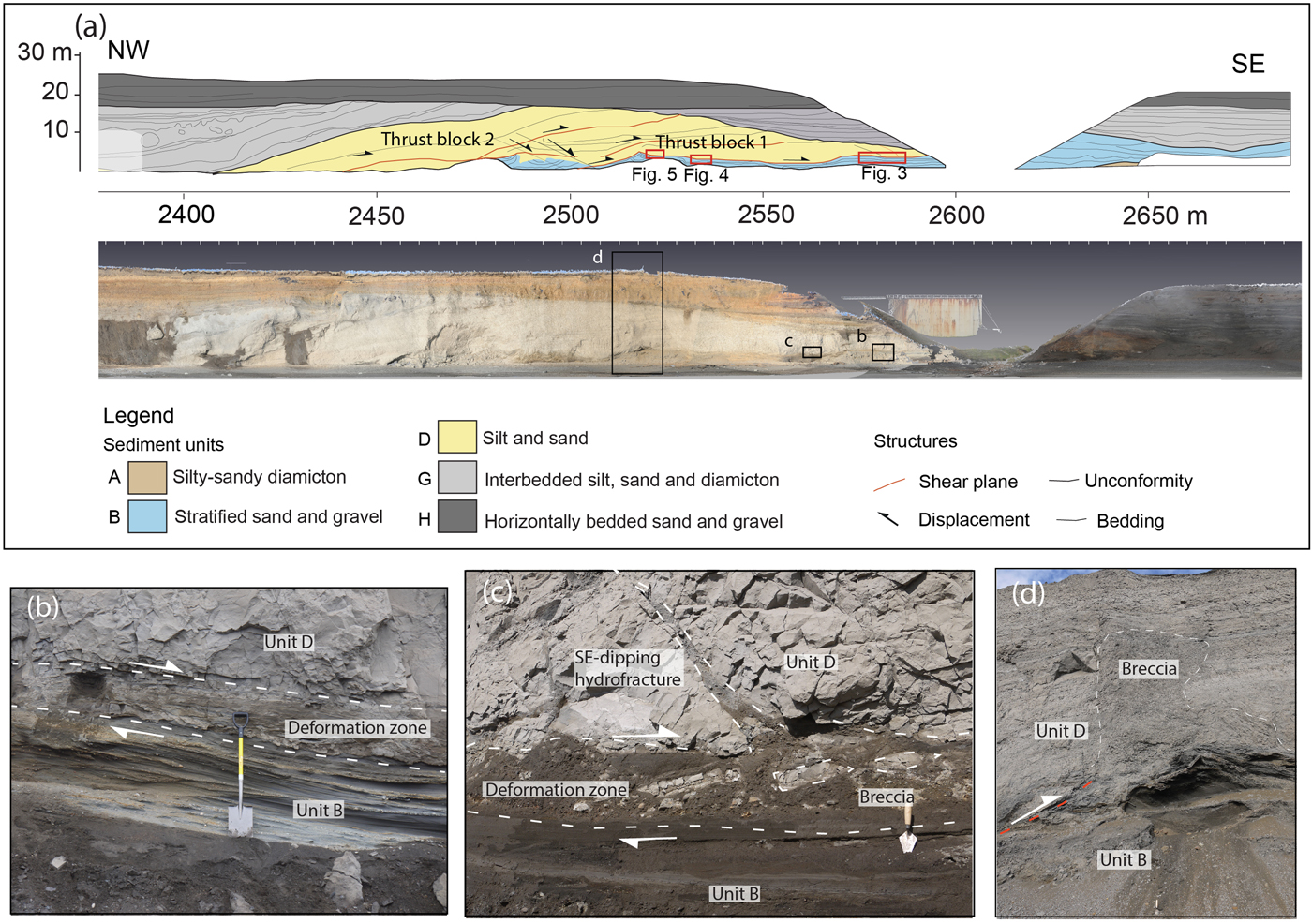
The ice-marginal thrust-block moraine at Ásgil is located approximately halfway across the Melabakkar-Ásbakkar coastal cliffs (2400–2600 m measured from the northern end of the cliffs; Fig. 1b). It comprises at least two stacked, gently northward-dipping thrust-bound blocks of compact, weakly stratified to massive glaciomarine silt and sand (unit D; Fig. 2a; Sigfúsdóttir et al., Reference Sigfúsdóttir, Benediktsson and Phillips2018). The silt is poorly sorted, locally clay rich, massive to weakly laminated, and relatively thickly bedded (the thickest beds are more than 1 m thick). The interbedded sand is sorted and considerably thinner bedded (up to ~10 cm). The silt and sand largely retain their primary bedding, but locally, mainly within the lower thrust block, the sediments have undergone ductile shearing (augen structures and folds) and homogenisation. Each thrust block is more than 150 m long and about 10 m thick and is dissected by a number of steeply inclined joints and southerly dipping normal (extensional) faults.
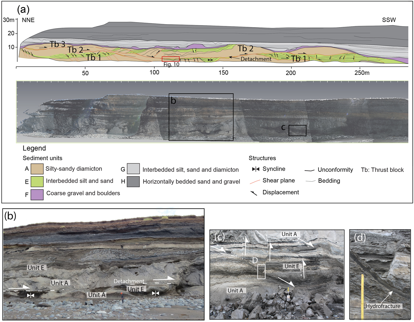
(a) A scale diagram and a LIDAR (light detection and ranging) scan of the Ásgil thrust-block moraine and overlying deposits (modified from Sigfúsdóttir et al., Reference Sigfúsdóttir, Benediktsson and Phillips2018). The scale bar indicates the distance from the northernmost point of the Melabakkar-Ásbakkar coastal cliffs. The red boxes indicate the sample locations and the area covered by Figures 3–5. The black boxes mark the locations of photographs in panels (b)–(d). The photographs show the detachment separating the thrust block from the footwall sand and gravel below. (b) A photo of the basal detachment at southern part of the Ásgil moraine. The deformation is focused within a ~50-cm-thick zone at the base of the thrust block, whereas the underlying deposits are largely undeformed (unit B). (c) A photo taken at ~2570 m showing elongated intraclasts (dashed outlines) within fluidised sand at the base of the thrust block. Hydrofractures infilled by coarse sands extend upward and dissect the overlying thrust block. (d) A photo taken at ~2520 m. The lower boundaries of the thrust block are diffused and deformed by folds and faults. A ~10-m-high and 2-m-thick clastic breccia extends upward into the thrust blocks, evidence of high water pressures. (For interpretation of the references to colour in this figure legend, the reader is referred to the web version of this article.)
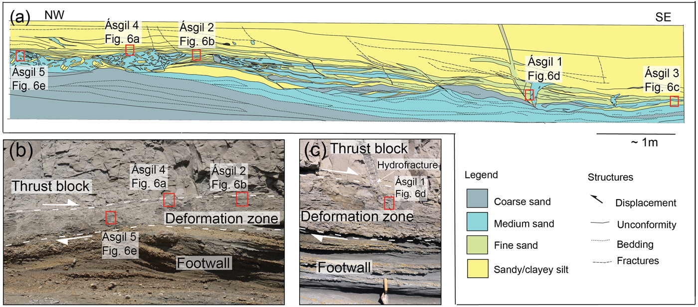
(colour online) (a) A section drawing showing the part of the detachment where samples Ásgil 1–5 were collected. The location is marked in Figure 2a. (b) A part of the detachment where samples Ásgil 2, 4, and 5 were collected. (c) A photograph of location of samples Ásgil 1. Note a trowel for scale.


Although not common, a small number of normal faults were observed crosscutting the detachment separating the thrust blocks, indicating that this phase of faulting postdated the development of the thrust stack. The base of the thrust stack rests on a few-metres-thick unit of stratified sand and gravel (unit B; Fig. 2a). These sands and gravels are folded and faulted and record a southward sense of shearing (based on vergence of folds and displacement along faults). The relative intensity of this deformation decreases toward the south. The sand and gravel can be traced laterally to the south of the thrust stack where they are unconformably overlain by a sequence of coarse gravel and boulders. This coarse-grained clastic sequence forms a greater than 15-m-thick and 200-m-wide multicrested sediment pile located on the ice-distal side of the thrust stack. Based on its sedimentology and stratigraphic location, Sigfúsdóttir et al. (Reference Sigfúsdóttir, Benediktsson and Phillips2018) interpreted this sequence as an ice-contact fan deposited during the same readvance that resulted in the construction of the adjacent thrust stack. Despite some localised folding and faulting, this fan does not exhibit any macroscale glaciotectonic structures indicative of subglacial shearing, which suggests that the fan was not overridden after its formation.
The thrust-block moraine and the ice-contact fan rest on a glaciomarine diamicton (unit A of Sigfúsdóttir et al., Reference Sigfúsdóttir, Benediktsson and Phillips2018), which is exposed in the foreshore at low tide. This silty-sandy diamicton probably directly overlies the underlying basalt bedrock as the latter crops out ~150 m farther toward the northwest. The thrust-block moraine is overlain by an undeformed, glaciomarine sequence of interbedded silts, sands, and diamictons (unit G; Fig. 2a), which were deposited after the glacier had retreated from this recessional limit. The glaciomarine sequence is in turn unconformably overlain by early Holocene littoral sand and gravel (unit H; Fig. 2a) deposited during the isostatic adjustment of the area (Ingólfsson, Reference Ingólfsson1987, Reference Ingólfsson1988).
At Ásgil, the present study has focused on the deformation associated with the transport and emplacement along the basal detachment of the thrust-block moraine
Macroscale description of the basal detachment
Southeast of ~2550 m (Fig. 2a), the lowermost part (~0.5–1 m) of the thrust block is characterised by a distinct deformation zone. This zone exhibits a number of erosive, crosscutting layers of sorted sand and gravel that are either massive or stratified. The crosscutting geometry of these layers is inconsistent with representing a primary (sedimentary) bedded sequence and can most simply be explained as hydrofractures formed by fracturing and subsequent infill by sediments (Rijsdijk et al., Reference Rijsdijk, Owen, Warren, McCarroll and van der Meer1999; van der Meer et al., Reference van der Meer, Kjær, Krüger, Rabassa and Kilfeather2009; Phillips et al., Reference Phillips, Everest and Reeves2012; Ravier et al., Reference Ravier, Buoncristiani, Menzies, Guiraud and Portier2015). These hydrofractures are commonly subhorizontal, formed semiparallel to the base of the thrust blocks and the primary bedding within these sediments (Figs. 2b, 2c and 3). Because of their location along the detachments, it is most likely that these crosscutting sediment-filled hydrofractures were formed as pressurised water exploited the basal detachment of the developing thrust-block moraine (see Microscale deformation structures) (Phillips and Merritt, Reference Phillips and Merritt2008). The largest sills (hydrofractures) are up to ~30 cm thick, have highly erosive margins, and are infilled with coarse sand and granule-sized gravel. The sediments filling these hydrofractures also locally contain angular, elongate to tabular-shaped blocks (up to ~50 cm long and 10 cm thick) of fine-grained silt and sand that are lithologically similar to the marine sediments contained within the overlying thrust block (Fig. 2c).
Although most of the hydrofractures form subhorizontal sill-like features, a number of high-angle to steeply inclined dykes, mostly dipping toward the southwest, were also observed (Fig. 2c). These steeply inclined sediment-filled fractures are up to ~20 cm wide and ~8 m in length and are filled by either a sandy breccia or well-sorted, stratified sand and gravel—the latter often exhibiting layering at an angle to the hydrofracture margins. These dyke-like features are rooted in the deformed basal zone and locally transect the entire thrust block. They are often (but not always) wedge shaped in form with the broadest part at the base of the thrust block, tapering toward the top located higher in the cliff, possibly suggesting that these sediment-filled features propagated upward from the base of the developing thrust stack.
The relative intensity of deformation within the basal detachment of this imbricate thrust stack gradually increases toward the north. Below this relatively thin deformed zone, in the southern part of the section, there is little evidence of glaciotectonic disturbance within the unit B sand and gravel indicating that negligible shear propagated downward into these underlying deposits (Figs. 2b, 2c and 3). In the northern part of the Ásgil section (between ~2450 and 2550 m; Fig. 2a), the contact between the thrust block and the underlying unit B stratified sand and gravel is poorly defined. In this area, these two tectono-sedimentary units appear to have been partially intermixed, possibly because of liquefaction and injection of sand and gravel upward into the base of the thrust block resulting in large-scale brecciation and disruption within the overlying thrust block (cf. Rijsdijk et al., Reference Rijsdijk, Owen, Warren, McCarroll and van der Meer1999) (Figs. 2d, 4 and 5). In the northern part of the section, the hydrofractures and their host deposits of unit D, as well as the underlying unit B sand and gravel, are folded and thrust repeated, with the vergence of the folds recording a sense of shearing toward the south. Both sediment units and the boundary between them are crosscut by minor faults, which cut the sediments at different angles.
Microscale deformation structures
Ten thin sections were collected within the lowermost part of the thrust block at Ásgil at three locations (Figs. 3, 4 and 5; see relative location in Fig. 2) in order to examine the deformation structures developed close to the southern leading edge of the thrust block (at ~2580–2590 m; Fig. 2a, samples Ásgil 1–5; Fig. 3) and farther north at a deeper structural level along the basal detachment (at 2520–2535 m; Fig. 2a, samples Ásgil 6–10; Figs. 4 and 5). In thin section, the fine sand, silt, and sandy diamicton, which not only form the thrust block but also the host sediments within the deformed, basal zone of the thrust stack, are lithologically similar indicating that they were derived from a similar source (provenance).
Microstructures developed close to the leading edge of the basal detachment (samples Ásgil 1–5)
The position of samples Ásgil 1–5 within the deformed zone marking the basal detachment close to the leading edge of the thrust-block moraine is shown in Figure 3. These thin sections reveal that, although on a macroscale this zone appears highly deformed, this deformation is less apparent on a microscale with the samples being largely composed of finely stratified silt and silty clay, with subordinate amounts of fine sand (Fig. 6a–c). The contacts between these layers are undulating to irregular in form and range from sharp to diffuse/gradational. The clay layers commonly possess a moderate to well-developed, layer-parallel plasmic fabric defined by optically aligned clay minerals. In sample Ásgil 4 (Fig. 6a), this birefringent clay (crossed polarised light) is locally fragmented with the fractures filled by homogenised silt and fine sand. In sample Ásgil 2 (Fig. 6b), and, to a lesser extent, samples Ásgil 3 (Fig. 6c) and 4 (Fig. 6a), the stratification is offset by at least one set of gently to moderately northwest-dipping (apparent dip in plane of section provided by the thin sections) normal microfaults and a set of moderately southeast-dipping structures. These small-scale faults (displacements on the order of a few millimetres) appear to show a close spatial relationship to the lenses and layers of coarser-grained sand.
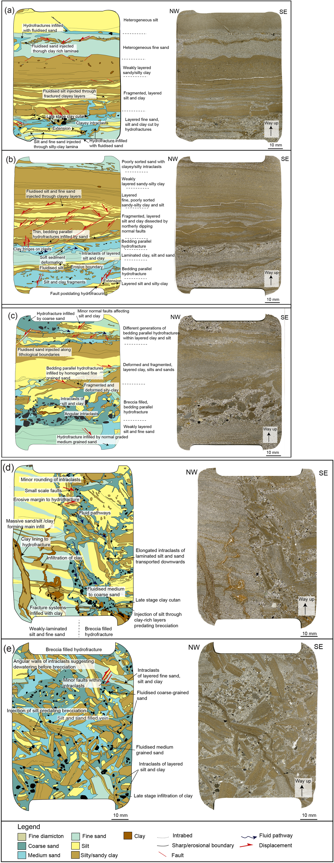
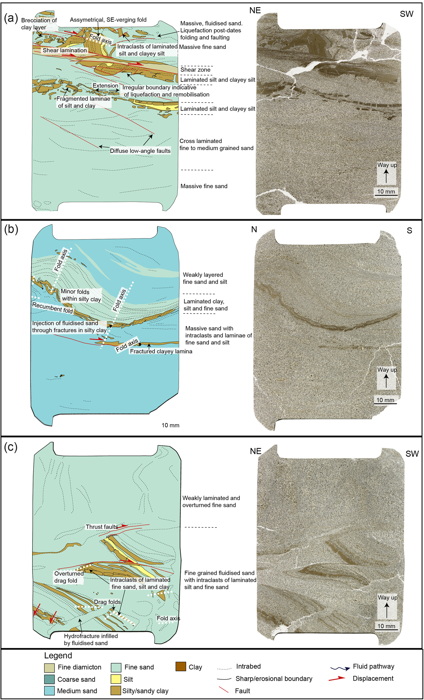
(colour online) Interpretation diagrams and scans of thin sections Ásgil 1–5. These thin sections were collected from a deformed zone at the base of the lowermost thrust block, close to the leading edge of the Ásgil moraine. Their relative location can be seen in Figure 3. These thin sections are dominated by layered, fine-grained sediments that have undergone repeated phases of sediment liquefaction, injection, and hydrofracturing. Samples Ásgil 4 (a), Ásgil 2 (b), and Ásgil 3 (c) are characterised by hydrofractures formed subparallel to the stratification of the fine-grained host deposits. Sample Ásgil 1 (d) shows the margins of a steep, breccia-filled hydrofracture. Sample Ásgil 5 (e) shows the infilling of a subhorizontal, breccia-filled hydrofracture.
The stratification within the fine silts and silty/sandy clays is locally crosscut and disrupted by irregular (erosive) lenses/layers of fine- to coarse-grained sand. These crosscutting relationships indicate that the introduction of these coarser-grained sediments postdated the formation of the stratification within the finer-grained sediments. The coarse sand is matrix poor (low clay content) and varies from massive (homogeneous) to weakly normally graded (fining upward). The coarse-sand grains are typically subrounded to rounded in shape, with the finer sand grains being more angular in appearance. Sand- and gravel-sized particles within these sediments are mainly composed of basaltic rock (lithic) fragments consistent with the predominantly basaltic bedrock in the region. Fresh, angular fragments of basaltic and silicic volcanic glass are also common detrital components. In sample Ásgil 3, the introduction of the coarse sand (see lower part of the thin section; Fig. 6c) resulted in the disruption/fragmentation of the adjacent stratified silt and fine sand. This coarse sand contains angular to irregular fragments of laminated silt and clay that are lithologically similar to, and therefore thought to have been derived from, the adjacent stratified sediments. Some of these clasts are composed of highly birefringent (under crossed polarised light) clay in which the optically aligned clay minerals define a moderate- to well-developed plasmic fabric. In samples Ásgil 2 (Fig. 6b) and 4 (Fig. 6a), the clay clasts within the medium-sand layers are much smaller in size and are more rounded in shape, indicative of a greater degree of rounding (abrasion) during transport. In sample Ásgil 4 (Fig. 6a), the medium-sand layer near the bottom of the thin section is linked to a fine-scale network of fractures (veins) filled by the same sediment. This network is injected into the adjacent clay and comprises two subvertical sand-filled veins connected to a number of subhorizontal veins, which occur parallel to the fine-scale lamination/stratification within the clay. The fine- to medium-sand layer in the upper part of this sample (Fig. 6a) contains a thin clay layer that is broken into a series of tabular segments with the intervening fractures filled by sand. Both the sand and clay layers are crosscut by an irregular vein of pale-coloured, medium-grained, matrix-poor sand. In the lower part of sample Ásgil 2 (Fig. 6b), the boundary between the medium- and fine-grained sand layers is complex and folded by a number of flame-like, asymmetrical disharmonic folds. The shape of these folds is consistent with an apparent sense of shear toward the southeast.
The microtextural relationships described previously suggest that the sand layers were injected into the preexisting stratified silts and clays. This process would have accompanied the brecciation and disruption of these fine-grained host sediments with the fragments dislodged from the walls of the developing sediment-filled hydrofracture being incorporated into the coarse sand during the injection process. The crosscutting relationships observed between the sand layers suggest that there were several phases of injection. Injection of the later coarser-grained sands, prior to the dewatering of the earlier formed sand, may have resulted in the observed soft-sediment deformation (disharmonic folding) in response to shear along the boundary between the two layers. In contrast, the more coherent silts and clays underwent brittle deformation with the normal (extensional) faulting as these stratified host sediments accommodated the expansion (increase in volume) of the sequence occurring in response to the injection of the liquefied coarse sand. In samples Ásgil 2 (Fig. 6b), Ásgil 3 (Fig. 6c), and Ásgil 4 (Fig. 6a), the coarser sand layers occur parallel/subparallel to the stratification within the host silt and silty clay indicating that injection of these sediments exploited this preexisting layering.
Samples Ásgil 1 (Fig. 6d) and Ásgil 5 (Fig. 6e) were taken from larger hydrofractures filled by a mud, clast-rich breccia, which is composed of elongated to irregular clasts of weakly stratified fine sand, silt, and clay set within a matrix of medium- to coarse-grained sand. The sandy matrix to the breccia varies from massive (sample Ásgil 1; Fig. 6d) to “patchy”/“mottled” in appearance because of the variation in its grain size from fine to coarse sand (sample Ásgil 5; Fig. 6e). Sample Ásgil 1 was taken from the margin of a prominent (up to 20 cm wide and 8 m long), steeply southeast-dipping, sediment-filled fracture system that crosscuts fine-grained weakly layered clayey silt, silt, and fine sand at the base of the thrust block (Fig. 3a and c). Sample Ásgil 5 (Fig. 6e) was collected from an approximately 50-cm-wide, subhorizontal breccia-filled hydrofracture that cuts through the finely layered sediments at the base of the thrust block (Fig. 3a and b). The laminated silt and clay intraclasts within the breccia range from being angular to rounded in shape, possibly reflecting a variation in the degree of rounding (abrasion) of the clasts during transport and injection of this coarse-grained sediment into the developing hydrofracture. However, the degree of rounding of these clasts appears to be dependent on lithology, with the sandy intraclasts tending to become more rounded with more diffused clast margins. The orientation of bedding preserved within the large clasts indicates that during transport (injection) they have been rotated (tilted) and possibly overturned. The clay layers within the clasts are locally broken, and the fractures infilled by silt and fine sand, indicating that these sediments have potentially recorded several phases of liquefaction, remobilisation, and injection prior to brecciation associated with the formation of the large-scale hydrofracture system. In sample Ásgil 1 (Fig. 6d), the margins of the hydrofracture are irregular, and it appears that some of the clasts contained within the breccia have been ripped (eroded) from the host sediments of this fracture system. Elongate clasts immediately adjacent to the wall of the hydrofracture show a preferred shape alignment parallel to or at a low angle to the margin of the fracture (Fig. 6d). In contrast, toward the interior of the vein the clasts are apparently more randomly orientated or may possibly define a subhorizontal preferred shape alignment (see Fig. 6d). In the lower, southeastern corner of the thin section, the breccia is cut by a complex network of clay veins. These veins are filled by finely laminated, highly birefringent clay (cutan). The sediments forming the host to this breccia-filled hydrofracture occur on the left-hand (northern) side of the thin section (Fig. 6d). The weakly developed to diffuse stratification developed within these silts and fine sands has an apparent dip toward the southeast. In the lower left-hand corner of the thin section, this stratification is crosscut by two thin (<10 mm) sediment-filled veins composed of clay and sandy clay (Fig. 6d). The larger of these two veins is layered with an outer layer of clay lining the fracture walls and a central infilling of massive clayey sand. A similar clay-filled, southeast-dipping vein was also observed cutting through the breccia within sample Ásgil 5 (Fig. 6e) where it is filled by weakly layered clayey silt and silt with this layering occurring parallel to the fracture walls.
Microstructures developed at a deeper structural level of the basal detachment (samples 6–10)
Thin sections Ásgil 6–10 (Figs. 7 and 8; Supplementary Fig. 1) were collected within the deformed zone associated with the basal detachment at a deeper structural level at the thrust-block moraine (Figs. 4 and 5). Sample Ásgil 9 (Supplementary Fig. 1) was collected from the thrust block and comprises homogenised silts and sands (a diamicton). Samples Ásgil 8 and 10 (Fig. 7) were taken from fine-grained sediments comprising the base of the thrust block and samples. Ásgil 6 and 7 (Fig. 8) were taken from subhorizontal hydrofractures that crosscut these fine-grained deposits (Figs. 4 and 5).
(colour online) Interpretation diagrams and scans of thin sections Ásgil 8 (a) and Ásgil 10 (b). These thin sections were sampled from the base of the lowermost thrust block at a structurally deeper part of the moraine. The location of the thin sections can be seen in Figures 4 and 5. They reveal fine-grain, stratified sediments that have undergone alternating phases of shearing (folding, faulting) and hydrofracturing.
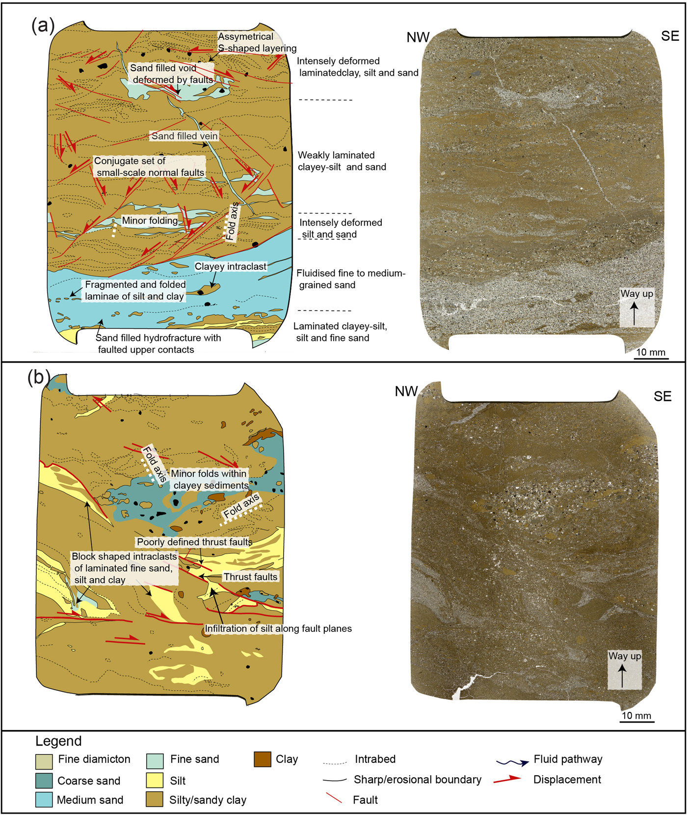
(colour online) Interpretation diagram and scans of samples Ásgil 6 (a) and Ásgil 7 (b). These thin sections were sampled from large hydrofractures dissecting the fine-grained sediment in the base of the lowermost thrust block at a structurally deeper part of the moraine. The locations of the thin sections can be seen in Figure 4.
Thin sections Ásgil 8 and Ásgil 10 (Fig. 7) are dominated by finely stratified silty clay, silt, and very fine sand, which are lithologically similar (grain size, sorting, and stratification) to the finely stratified clay, silt, and sand forming the host to the hydrofracture system in samples Ásgil 1–5 (Fig. 6). However, much more disruption is observed in samples Ásgil 8 and 10 (Fig. 7). The sediments have a mottled appearance as the stratification is diffused/gradational and the beds/laminae are undulating and discontinuous. This may possibly be attributable to an increase in the amount of layer-parallel shear accommodated by the laminated sediments within this structurally deeper and more complex part of the basal detachment. In sample Ásgil 8 (Fig. 7a), the stratification is mostly subhorizontal/weakly folded with the disruption of the layers increasing upward. The stratification is offset by a poorly defined, conjugate set of normal microfaults with apparent dips both toward the northwest and southeast. In the lower part of this finely stratified subunit, the faults have a moderate to steep dip, but in the upper part, the faults tend to have lower dips. In the upper part of sample Ásgil 8 (Fig. 7a), the layers are tilted between two of these low-angle faults resulting in an asymmetrical S-shaped layering between these two faults. The faulted and folded stratified sediments are truncated by an apparently southeast-dipping sand vein (see Fig. 7a). The vein is about 0.5 mm thick with a sharp boundary and a steplike form and is infilled with massive fine-grained sand with high intergranular porosity. The crosscutting, erosive geometry, and sorted infilling is consistent with this sand vein being formed by injection and subsequent deposition of the sand. A larger sand vein/hydrofracture dominates the lowermost part of thin section Ásgil 8 (Fig. 7a). This hydrofracture is seen in the lower ~4 cm of the thin section where it has an apparent dip toward the northwest. The sediments within it comprise medium-grained sand that is lithologically similar to the sands seen in samples Ásgil 6 and Ásgil 7 (see below). The sand typically possesses a high intergranular porosity and low matrix content. The individual sand grains are subrounded to angular in shape. Within the sand are fragmented silt and clay laminae, as well as variably aligned fragments (intraclasts) of silty clay, which define a weakly developed/preserved layering that dips toward the northwest. The intraclasts have smooth edges indicative of rounding during transport. The upper boundary of the hydrofracture is defined by an approximately 1-cm-thick deformed layer of unsorted silt, sand, and clay that is offset by a set of northwest-dipping faults associated with small-scale folds. The faults are crosscut by the sand vein, so the injection of the sand postdated the small-scale faulting of the host sediments. In sample Ásgil 10 (Fig. 7b), the stratification within the clayey silt/silty clay is highly disrupted, and the laminae are tilted, folded, and possibly overturned. In between the clay-rich layers that dominate the thin section are layers of sorted silt and very fine sand with sharp boundaries. In the middle-upper part of the thin section is a lens of coarse-grained sand with diffused edges. All these sediments are dissected by a number of faults. The faults are poorly defined, and some have sand lining possibly deposited by water flowing along the fault walls. The faults have a very gentle to moderate dip toward the southeast (apparent dip), but because of complex deformation of the sample, it was difficult to estimate the direction of offset along the fault planes, although most of them appear to record apparent displacement toward the southeast.
Samples Ásgil 6 and 7 (Fig. 8) were taken from subhorizontal layers of sand with erosional margins, consistent with being hydrofractures (Fig. 4). The thin sections show that the sand within the hydrofractures is weakly stratified to heterogeneous and is interbedded with layers of silt and clayey silt possibly reflecting fluctuations of the velocity of the water flowing through the fractures. The sand is fine to medium grained and possesses an intergranular porosity and variable amounts of a fine-grained matrix. Most of the sand grains are subrounded to angular in shape and composed of a similar range of components as the sand layers in samples Ásgil 1–5 (Fig. 6). The contacts between the layers are irregular, and the silty-clay layers tend to be very fragmented, possibly because of brecciation of the rigid clay layers in response to the liquefaction and ductile deformation of the open-packed silt and sand. Although the alignment of elongate clasts appears to preserve the original stratification within the hydrofractures, some of the clay fragments are randomly dispersed within the sand indicating the longer transport path of these clasts. These “dispersed” fragments tend to have rounded and rather diffuse edges. The weakly preserved stratification is deformed by a number of upright to steeply inclined, asymmetrical, southeast-verging folds (Fig. 8). This indicates that after the hydrofractures formed, the sediments underwent a minor folding, possibly as a result of transmission of shear into the deposits during the thrust-block transport.
Overall, samples Ásgil 6 to 8 and 10 (Figs. 7 and 8) show higher intensity of faulting and folding compared with thin sections Ásgil 1–5 (Fig. 6). This is consistent with the observed, larger-scale increase in complexity and magnitude of deformation toward the northern, structurally deeper part of the detachment. The lithologic similarities and the tectonostratigraphic location of the finely layered silty clay, silt, and sand (see Ásgil 8 and 10; Fig. 7) to those seen at the front of the thrust (Ásgil 1 to 5; Fig. 6) may suggest that these are part of the same deformation/hydrofracture zone. However, the fine-grained host sediments and the crosscutting hydrofracture system seen in thin sections Ásgil 1–5 (Fig. 6) have lost some of their identity because of folding and faulting resulting from increased shearing transmitted into the deposits, probably because of increased overburden pressures during thrust stacking. Shearing was interrupted by events of sediment liquefaction and injection resulting in brecciation and hydrofracturing. The hydrofractures may have developed along weaknesses in the sediments, both parallel to bedding and along preexisting fault planes. The new hydrofractures also underwent faulting and folding to different degrees (Ásgil 6 to 8 and 10; Figs. 7 and 8). This indicates that the level of friction and transmission of shear varied along the detachment, possibly because of fluctuating porewater pressures related to hydrofracturing and water escape.
Melaleiti thrust-block moraine
The thrust-block moraine at Melaleiti is located in the northernmost part of the Melabakkar-Ásbakkar coastal cliffs. It is more than 300 m across and 10 m high and comprises several subhorizontal or gently north-dipping, stacked thrust-bound allochthonous blocks (Fig. 9). Each block is composed of two main sedimentary units—a massive, silty-sandy, very compact, and deformed glaciomarine diamicton of unit A, and unit E consisting of interbedded silt and sand with occasional, thin layers of gravel and diamicton (Sigfúsdóttir et al., Reference Sigfúsdóttir, Benediktsson and Phillips2018). The thrust blocks are dissected by a large number of normal (extensional) faults with a dominant dip toward the southeast (Fig. 9), although some dip toward the northwest. The relative complexity of deformation and intensity of faulting/thrusting decreases to the southwest (ice-distal part). This probably reflects a decrease in strain away from the ice front during the thrust stacking (Sigfúsdóttir et al., Reference Sigfúsdóttir, Benediktsson and Phillips2018).
(a) A scale diagram and a LIDAR (light detection and ranging) scan of the Melaleiti thrust-block moraine (modified from Sigfúsdóttir et al., Reference Sigfúsdóttir, Benediktsson and Phillips2018). The red box indicates the sample locations and the area covered by Figure 10. The black boxes on the LIDAR scan indicate the locations of photos in panels (b)–(d). The numbers on the section diagram indicate different thrust blocks. (b) A photograph taken at ~140 m showing sharp lower contact (white dashed line) between a thrust block above and the deformed silt and sand below. (c) A photograph taken at ~220 m showing faults dissecting the intrabedded silt and sand and the thrust block above. The large normal fault seen in the middle part of the photo is infilled by massive sand. (d) A close-up photograph of the sediment-filled normal fault (hydrofracture) in panel (c). The yellow scale is about 30 cm. (For interpretation of the references to colour in this figure legend, the reader is referred to the web version of this article.)
(colour online) (a) A diagram showing the part of the basal detachment where samples Mel 11–16 were collected. The location is marked in Figure 9a. (b) A photograph of the sampling location.

The moraine is overlain by an up to 2-m-thick unit of coarse gravel (unit F in Fig. 9a). This unit is interpreted as having been deposited under high pressure in a subglacial setting, which indicates that the moraine was overridden by the glacier. However, it is unclear if it was overridden by the same or a younger advance (Sigfúsdóttir et al., Reference Sigfúsdóttir, Benediktsson and Phillips2018). The original structure of the moraine is preserved indicating that it did not undergo extensive subglacial deformation during the overriding. However, some of the normal faults that crosscut (postdate) the thrusts-bound blocks were possibly developed in response to extensional deformation as the glacier overrode the moraine (Sigfúsdóttir et al., Reference Sigfúsdóttir, Benediktsson and Phillips2018).
Macroscale description of the basal detachment
This study focuses on a more than 150-m-long detachment in the southernmost part of the thrust stack (~100–250 m; Fig. 9a). The base of the thrust block is very sharp, and the deposits in the footwall (both units E and A) are variably deformed. The relative intensity of this deformation decreases southward toward the leading edge of the thrust-block moraine. In the northern part, between ~100 and 180 m, the sediments are deformed by numerous folds and boudins, which are crosscut by normal and reverse faults bounded by subhorizontal shears (Fig. 9b). The geometry of these faults suggests that they developed as subhorizontal Reidel shears (Y shears) within the footwall of the basal detachment confining a zone of normal and reverse faults (R and P shears) developed at an angle to the main direction of transport (Phillips and Lee, Reference Phillips, Lee, Phillips, Lee and Evans2011). The majority of the normal and reverse faults do not crosscut the main detachment, indicating that they predated or were developed at the same time as this larger-scale structure. Closer to the leading edge of the thrust-block moraine (between ~180 and 300 m; Fig. 9a), the bedded silts and sands have undergone less penetrative deformation. For example, the bedded unit E sediments are relatively intact, although crosscut by a large number of well-defined, southeast- and northwest-dipping normal faults (Fig. 9c). Based on the observed crosscutting relationships, these faults are interpreted as both predating and postdating the thrust detachment. A small number of the faults are infilled/lined by massive and stratified sand indicating deposition by running water and therefore suggesting that these faults were exploited as fluid pathways/hydrofractures. These hydrofractures are relatively thin (up to ~3 cm), and usually, they crosscut other structures indicating that they were formed during the late stage of the deformation (Fig. 9d).
Microscale deformation structures
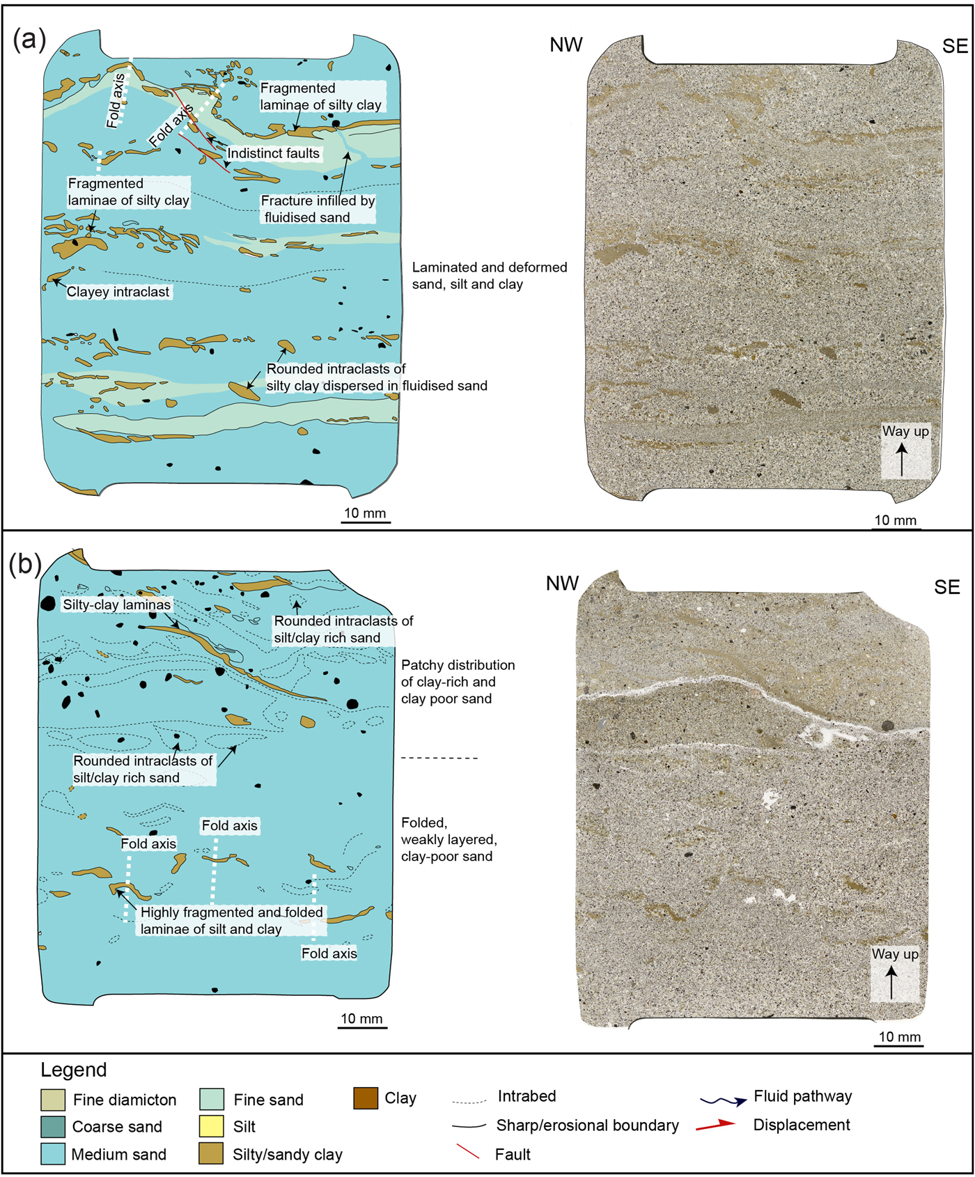
Six thin sections were taken from samples collected at ~110 m (Fig. 9a), from the glaciomarine interbedded silt, sand, and diamictons of unit E located immediately below the southernmost thrust detachment (Fig. 10). Three of them are described subsequently (Mel 11, 14, and 16; Fig. 11), and the remaining three (Mel 12, 13, and 15) are available as Supplementary Material (Supplementary Fig. 2). The Mel 11 to 16 thin sections contain moderately to well-sorted, open-packed, fine- to medium-grained sand (Fig. 11; Supplementary Fig. 2). The sand grains are usually subrounded to angular in shape and mainly consist of basaltic rock (lithic) fragments. Fresh, angular fragments of volcanic glass are also common. The sand layers are interbedded with thinner layers of silt and silty clay. The contacts between well-sorted silt and sand layers are commonly diffusive, and locally they appear interdigitate, which could indicate local liquefaction and subsequent mixing of these sediments. The more rigid, clay-rich layers have undergone brecciation and extension (boudinage), most likely in response to/accompanying the liquefaction of the adjacent sand (Fig. 11). Locally, the clayey intraclasts are dispersed within the fluidised silt and sand (see upper part in sample Mel 16; Fig. 11a), although they usually have sharp edges and are often aligned and partly preserve the primary layering indicating a short transport pathway. The bedded/laminated clays, silts, and sands are locally folded with the vergence of folds recording an apparent sense of shear toward the southwest (see Mel 14; Fig. 11b). In the lower half of thin section Mel 11 (Fig. 11c), the folded, bedded/laminated clay, silt, and sand are crosscut by a vein infilled by open-packed fine sand. Within this sand layer, there are intraclasts of laminated sand, silt, and clay with smooth edges. This relationship suggests that the sand layer was injected into the preexisting interlaminated sediment resulting in hydrofracturing and brecciation of the host sediments. Intraclasts from the host sediments would then be incorporated into the sediments being injected into the developing hydrofracture. As described previously, the deformed unit E sediments are crosscut by a number of shears and faults, some of which are clearly visible in thin section (e.g., Mel 16; Fig. 11a).
(colour online) Interpretation diagram of samples Mel 16 (a), Mel 14 (b), and Mel 11 (c). The samples were collected from bedded/laminated glaciomarine sand and silt/clay located below the thrust-block detachment. The sampling locations are marked in Figure 10. These thin sections reveal that the folded interlaminated sediments are crosscut by hydrofractures and faults/shears.
DEVELOPMENT OF THE ÁSGIL AND MELALEITI THRUST-BLOCK MORAINES: A SEQUENTIAL MODEL AND DISCUSSION
The detailed macro- and microscale study of the detachments within the Ásgil and Melaleiti thrust moraines shows that their development was accompanied by repeated phases of sediment liquefaction, injection, and hydrofracturing. The observed microstructural relationships indicate that these processes occurred during the transport and emplacement of the autochthonous sediment blocks. This sequence of events associated with the detachment, transport, and emplacement of thrust blocks in the moraines can be explained in terms of a detailed four-stage model (Fig. 12).
(colour online) A sequential model explaining the formation of the moraines. See text for detailed description. Stage 1: As the glacier advanced across the seafloor, water pressures rose within the glaciomarine sediments. Porewater pressures build up within silt and sand layers sealed between less permeable deposits. This caused liquefaction of the silt and sand enabling large sediment blocks to decouple from the underling sediments/or bedrock. Stage 2: The sediment blocks were transported forward because of gravity spreading and ice push. Repeated phases of sediment liquefaction and injection occurred along the earlier developed detachment resulting in formation of a complex hydrofracture system along the base of the sediment blocks. The deformation associated with the transport was focused within this relative thin, water-lubricated zone. Stage 3: The dislocated thrust blocks were stacked at the ice margins to form thrust-block moraines. The thrust blocks were accreted on top of highly permeable deposits of sands and gravels. Initially, the thrust blocks slid over the water-saturated sands and gravels without much internal deformation, but with increased sediment draining and elevated overburden pressures, the friction increased. This resulted in folding and faulting separated by events of hydrofracturing and water escape. Stage 4: Further draining of the sediments led to brittle deformation (faulting) and lockup of the thrust blocks. The Melaleiti moraine was subsequently overridden, but the Ásgil moraine was not (Sigfúsdóttir et al., Reference Sigfúsdóttir, Benediktsson and Phillips2018).

Stage 1: detachment
The structural architecture of the moraines exposed in Melabakkar-Ásbakkar indicates that they formed in response to south/southeastward-directed ice push by a glacier advancing from Borgarfjörður (Fig. 1b) (Ingólfsson, Reference Ingólfsson1987, Reference Ingólfsson1988; Sigfúsdóttir et al., Reference Sigfúsdóttir, Benediktsson and Phillips2018). Thus, the thrust blocks comprising the moraines at Ásgil and Melaleiti can be assumed to be derived offshore, north/northwest of the study site. As the moraines were formed in a submarine setting (Ingólfsson, Reference Ingólfsson1987, Reference Ingólfsson1988; Sigfúsdóttir et al., Reference Sigfúsdóttir, Benediktsson and Phillips2018), the sediment blocks that were detached, displaced, and stacked to form the thrust-block moraines were presumably unfrozen and water saturated during glaciotectonism.
The earliest phase of deformation recorded by the thrust-block sediments at Ásgil is the liquefaction of the silt and fine-grained sand layers toward the base of the thrust block, indicative of increasing porewater pressures within the sediments as they are being deformed. Although it is uncertain if the liquefaction occurred during detachment or at a later stage during thrust-stack development, it would have dramatically lowered the shear strength of the sediment facilitating deformation and enabling low-frictional detachments to form within the substratum (Moran et al., Reference Moran, Clayton, Hooke, Fenton and Andriashek1980; Bluemle and Clayton, Reference Bluemle and Clayton1984; Phillips et al., Reference Phillips, Merritt, Auton and Golledge2007; Phillips and Merritt, Reference Phillips and Merritt2008; Burke et al., Reference Burke, Phillips, Lee and Wilkinson2009; Vaughan-Hirsch et al., Reference Vaughan-Hirsch, Phillips, Lee and Hart2013) (Fig. 12, stage 1). Detachments typically develop within weak, sorted sand and silt layers contained (sealed) between more impermeable layers (clay, diamicton, bedrock) enabling porewater pressures to build up within the silts and sands (Bluemle and Clayton, Reference Bluemle and Clayton1984; van der Wateren, Reference van der Wateren1985; Croot, Reference Croot1987; Boulton and Caban, Reference Boulton and Caban1995; Phillips and Merritt, Reference Phillips and Merritt2008; Vaughan-Hirsch and Phillips, Reference Vaughan-Hirsch and Phillips2017) (Fig. 12, stage 1). Consequently, laterally extensive, subhorizontal beds of silt/sand within the glaciomarine deposits at Melasveit are considered to have provided a focus for initial deformation, leading to thrust propagation and the detachment of the slablike sediment blocks.
Elevated porewater pressures within ice-marginal/proglacial sediments are likely to occur because of ice load, tectonic thickening, and basal shear stress applied by the advancing glacier (van der Wateren, Reference van der Wateren1985; Boulton and Caban, Reference Boulton and Caban1995). Also, it is likely that preferential flow of subglacial meltwater toward the ice margin from compressed subglacial deposits farther upglacier and/or external sources (i.e., surface melting) might have contributed to further elevating the water content/pressures within the deforming sequence (Boulton et al., Reference Boulton, Dobbie and Zatsepin2001, Vaughan-Hirsch and Phillips, Reference Vaughan-Hirsch and Phillips2017). Syntectonic subaquatic outwash sediments forming lenticular aprons/fans along the leading edge of some of the moraines in Melasveit (i.e., Ásgil) indicate that the large-scale glaciotectonism at Melasveit was associated with high meltwater fluxes (Sigfúsdóttir et al., Reference Sigfúsdóttir, Benediktsson and Phillips2018). This relationship, as well as evidence for sustained pressurised water flow along the developing detachments (see Stage 2 and 3), may even be used to support that the advances that resulted in the formation of the moraines were a result of accelerated ice flow or possibly surging. This is because a rapid application of glaciotectonic stress would have favoured overpressurisation of the subglacial meltwater and, thus, formation of thrust-block moraines (e.g., Kamb et al., Reference Kamb, Raymond, Harrison, Engelhardt, Echelmeyer, Humphrey, Brugman and Pfeffer1985; Kamb, Reference Kamb1987; Piotrowski and Tulaczyk, Reference Piotrowski and Tulaczyk1999; Fischer and Clarke, Reference Fischer and Clarke2001; Kjær et al., Reference Kjær, Larsen, van der Meer, Ingólfsson, Krüger, Benediktsson, Knudsen and Schomacker2006; Phillips et al., Reference Phillips, Lipka and van der Meer2013, Reference Phillips, Cotterill, Johnson, Crombie, James, Carr and Ruiter2018).
Stage 2: proglacial/ice-marginal thrusting and movement along the décollements
Because of gravity spreading and compression from the rear caused by the weight gradient at the ice margins and the ice flow, respectively (Fig. 12, stage 2) (Rotnicki, Reference Rotnicki1976; Pedersen, Reference Pedersen, Jones and Preston1987; Aber et al., Reference Aber, Croot and Fenton1989; van der Wateren, Reference van der Wateren1995; Bennett, Reference Bennett2001; Pedersen, Reference Pedersen2005; Aber and Ber, Reference Aber and Ber2007; Sigfúsdóttir et al., Reference Sigfúsdóttir, Benediktsson and Phillips2018), the detached sediment blocks were “pushed”/“displaced” forward by the advancing glacier (Fig. 12, stage 2). The transport of the allochthonous sdiment blocks was most likely aided by continued elevated porewater pressures and fluid flow being maintained along the earlier formed detachments. Evidence for this is provided by the repeated phases of liquefaction and injection along these décollement surfaces, thereby minimising the amount of shear being transmitted into the adjacent sediments and facilitating the displacement of the large slabs of unconsolidated sediments by the advancing ice. The detachments would have acted as fluid pathways, focusing water escape within the relatively clay-rich glaciomarine sequence and facilitating the southward migration of water through the deforming sediment pile.
At Ásgil, the complex, crosscutting sets of hydrofractures and associated brecciation of the sediments within a relatively thin “deformation zone” at the base of the thrust block clearly indicate that water pressures within the deforming sediment pile repeatedly exceeded the cohesive strength of these deposits. Crosscutting relationships between different generations of hydrofractures observed in the thin sections imply that the grain size of the sediments infilling this evolving hydrofracture system generally increased (Fig. 12, stage 2). This may be explained by increasing water pressures, widening of the hydrofractures, or simply the increased availability of coarse-grained sediments as the thrust block overrode the subaquatic fan deposited in front of the evolving moraine (see stage 3). Well-defined, sharp, erosive contacts between the hydrofractures show that they were probably formed in response to several phases of injection and fragmentation of the sediments between periods of partial solidification of the deposits rather than gradual changes in flow regime during a single event (Fig. 12, stage 2). These variations could either be because of fluctuations in the submarginal hydrology (water input) or release of hydrostatic pressure because of periodic water escape toward the front of the evolving imbricate thrust stack. This potentially resulted in a stick-slip type of movement along water-lubricated surfaces (subhorizontal hydrofractures) developed along the base of the thrust blocks (Boulton et al., Reference Boulton, Dobbie and Zatsepin2001; Phillips and Merritt, Reference Phillips and Merritt2008). The movement was largely focused along those water-lubricated surfaces that were active at a particular moment but may then have switched following local drainage and activation of new water-lubricated thrusts.
Stage 3: development of the thrust-block moraines
The dislocated thrust blocks were accreted at the ice margin leading to the formation of the glaciotectonic thrust-block moraines (Fig. 12, stage 3). At Melaleiti, the thrust blocks were emplaced on a less compact and permeable sequence of interbedded silt, sand, and gravel of the underlying thrust blocks. Similarly, at Ásgil, the detached thrust blocks were emplaced on a sequence of ice-marginal sands and gravels, which were deposited at an earlier stage during the readvance. Despite the high permeability of these underlying deposits, which would have facilitated drainage of the proposed water-lubricated basal detachments, the lowermost block is thought to have been transported across the coarser-grained sediments in the footwall resulting in little disturbance of these sediments below the leading edge of the thrusts (Fig. 12, stage 2). This is thought to indicate that, initially, the leading edges of the thrust blocks were in effect “decoupled” from the underlying sediments, possibly indicating that the rate of subglacial meltwater being transmitted through the basal detachment temporarily exceeded the rate at which water was dissipated through the footwall sediments. The subaquatic setting may have aided this process because of the water-saturated sediments and relatively low hydraulic gradient at the margins, which may have led to slower meltwater release. Furthermore, consistently high subglacial water pressures are maintained below water-terminating glaciers as the minimum value is determined by the pressure exerted by the proglacial water column (Benn et al., Reference Benn, Warren and Mottram2007; Sugiyama et al., Reference Sugiyama, Skvarca, Naito, Enomoto, Tsutaki, Tone, Marinsek and Aniya2011). All this may have contributed to low effective pressures and facilitated low frictional sliding of the glacier and the thrust blocks.
Eventually, however, the presence/introduction of highly permeable sand and gravel within the footwall of the thrust, possibly coupled with increasing overburden pressures below the evolving thrust-block moraine, resulted in the partial dewatering of this basal detachment and increased effective pressures. This led to an increased cohesive strength of the sediments and frictional drag between the allochthonous thrust block (hanging wall) and the underlying footwall. This process resulted in the locking up of the basal décollement and possibly contributed to further accretion of the thrust block onto the up-ice side of the evolving glaciotectonic landform (Fig. 12, stage 3).
The northward increase in the relative intensity of deformation (folding, faulting) within the up-ice sections of both the Ásgil and Melaleiti (Figs. 2 and 9) moraines is consistent with increased amount of shearing within the structurally deeper parts of the evolving glaciotectonic landforms (Fig. 12, stage 3). Detailed analysis of the thin sections taken from the base of the thrust blocks and the footwall sediments within the structurally deeper parts of the moraines reveal that this deformation involved a complex interplay between ductile shearing (folding and faulting) and sediment liquefaction, injection, hydrofracturing, and brecciation (Fig. 12, stage 3).
Large hydrofractures formed within the Ásgil moraine during this phase of thrust stacking, extending from the sands and gravels in the footwall, and cutting upward into the overlying, rigid thrust block. The upward infilling is consistent with potential formation of these hydrofractures in a submarginal/proglacial setting where the pressurised water at depth is able to escape up toward the surface because of the decrease in overburden pressures (Boulton and Caban, Reference Boulton and Caban1995; van der Meer et al., Reference van der Meer, Kjær, Krüger, Rabassa and Kilfeather2009; Phillips et al., Reference Phillips, Everest and Reeves2012; Ravier et al. Reference Ravier, Buoncristiani, Menzies, Guiraud and Portier2015). Although, the Melasveit moraines were formed in a subaquatic setting, which would have affected the stress gradient at the margins, the development of the hydrofractures most likely followed a similar pattern as recorded in terrestrial settings because of lower overburden pressures toward and in front of the grounded ice margins (Benediktsson et al., Reference Benediktsson, Möller, Ingólfsson, van der Meer, Kjær and Krüger2008, Reference Aber, Croot and Fenton2010; Phillips et al., Reference Phillips, Lipka and van der Meer2013; Ravier et al., Reference Ravier, Buoncristiani, Menzies, Guiraud and Portier2015). The large hydrofractures suggest that the pressures within the subglacial hydrogeologic system temporarily increased during the late stage of the glaciotectonism, possibly because of increasing overburden pressures during the displacement and accretion of the thrust blocks onto the up-ice side of the evolving glaciotectonic landform. Additionally/alternatively, the impermeable sediment within the thrust blocks, coupled with the deposition of an ice-marginal fan/apron, may have impeded the escape of meltwater from beneath the ice margin, resulting in an increased hydrostatic pressure within the subglacial hydrogeologic system. The hydrofracturing led to increased permeability of the thrust stack and possibly facilitated a decrease in water pressures below the evolving thrust-block moraine (Phillips et al., Reference Phillips, Everest and Reeves2012).
Stage 4: emplacement
The fall in water pressures within the deforming sediments coupled with hydrofracturing and fluid escape toward the leading edge of the evolving thrust stack resulted in dewatering of the deforming sediment pile (Fig. 12, stage 4). This, in turn, led to progressive increase in friction between the base of the thrust blocks and the underlying deposits (Phillips et al., Reference Phillips, Merritt, Auton and Golledge2007; Benediktsson et al., Reference Benediktsson, Möller, Ingólfsson, van der Meer, Kjær and Krüger2008, Reference Benediktsson, Schomacker, Lokrantz and Ingólfsson2010) contributing to the cessation of displacement of the allochthonous blocks and their accretion onto the up-ice side of the evolving thrust-block moraine. Field evidence from both Ásgil and Melaleiti indicates that the initial ductile deformation structures (i.e., folds) and hydrofractures are postdated by discrete faulting and thrusting, recording a switch from ductile to brittle deformation associated with the dewatering of the deforming sequence. The crosscutting relationship between the faults and the detachments at the base of the thrust blocks clearly indicates that these moderate to high-angle brittle structures developed both prior to and after the final emplacement of the thrust blocks. At Ásgil, most of the faults are small and only record minor displacement (up to a few decimetres). However, at Melaleiti, a high number of larger-scale faults and subhorizontal shears were observed crosscutting the earlier developed ductile structures within the high-strain zone at the base of the thrust blocks. Most of the faults dip toward the southeast (down-ice) and probably formed initially as down-ice dipping Reidel shears in response to simple shear (cf. Phillips and Lee, Reference Phillips, Lee, Phillips, Lee and Evans2011) related to the riding of the structurally higher thrust block over the underlying thrust block, which had already been emplaced.
CONCLUSIONS
Based on a microscale study of detachments within two ice-marginal thrust-block moraines in Melasveit, western Iceland, we propose a detailed structural model for processes occurring during glaciotectonic thrusting, including the detachment, transport, and accretion of large, rigid sediment blocks.
The initial detachment of the sediment blocks most likely took place in response to ice push and gravity spreading at the margins of the advancing glacier. Overpressurised submarginal/proglacial groundwater led to fluidisation of bedded/laminated glaciomarine sediments and detachment along water-lubricated layers.
The transport of the sediment blocks was aided by elevated porewater pressures along the detachments. This minimised the amount of shear transmitted into the large, unconsolidated, and unfrozen sediment blocks allowing them to be transported by the glacier. Water pressures within the deforming sediment pile repeatedly exceeded the cohesive strength of these blocks during emplacement and accretion resulting in hydrofracturing and fluid escape toward the front of the thrust blocks.
The leading edges of the thrust blocks were in effect “decoupled” from the underlying sediments resulting in only minor disturbance of the footwall. However, the relative intensity of deformation (folding, faulting) increased up-ice, as well as the amount of shearing within the structurally deeper parts of the evolving glaciotectonic landforms.
During the final stages of the formation of the thrust-block moraines, a switch from ductile to brittle deformation was associated with partial dewatering and fall in water pressures. This resulted in the cessation of displacement of the blocks and their accretion onto the up-ice side of the evolving thrust-block moraine.
This study stresses the role of overpressurised porewater within submarginal/pro-glacial sediments in the transport of unfrozen and unlithified thrust blocks during large-scale glaciotectonism. The hydrogeology along with the lithologic characteristics of the deforming sediments were the key factors in controlling the changing style of deformation during the detachment, transport, and accretion of the thrust blocks.
SUPPLEMENTARY MATERIAL
The supplementary material for this article can be found at https://doi.org/10.1017/qua.2019.48.
ACKNOWLEDGMENTS
This project was funded by the Icelandic Research Fund (grant no. 141002-051 to Í. Ö. Benediktsson) and the Royal Physiographic Society in Lund (grants to T. Sigfúsdóttir and Í. Ö. Benediktsson). Additional support was provided by the British Geological Survey (to E. Phillips). We would like to thank Heimir Ingimarsson, Sandrine Roy, and Kim Teilmann for their assistance in the field. Thanks are also due to Rob Storrar and an anonymous referee for constructive reviews that improved this paper. E. Phillips publishes with permission of the executive director of the British Geological Survey.


 Open access