


1. Introduction
The guiding and focusing of intense electromagnetic waves in plasma channels (Ehrlich et al. Reference Ehrlich, Cohen, Zigler, Krall, Sprangle and Esarey1996; Esarey et al. Reference Esarey, Sprangle, Krall and Ting1997; Hubbard et al. Reference Hubbard, Hafizi, Ting, Kaganovich, Sprangle and Zigler2002) have a wide range of applications in fusion plasma, harmonic generation and laser–plasma accelerators (Nishida, Sato & Nagasawa Reference Nishida, Sato and Nagasawa1987; Gibbon & Förster Reference Gibbon and Förster1996; Pukhov, Sheng & Meyer-ter Vehn Reference Pukhov, Sheng and Meyer-ter Vehn1999; Ganguli et al. Reference Ganguli, Tarey, Arora and Narayanan2016; Kaw Reference Kaw2017; Das Reference Das2020). Many of these applications require tight focusing of high-intensity lasers. In vacuum, a high-intensity laser can propagate up to a few Rayleigh lengths $(X_R=\pi r_0^2/\lambda )$
without diffraction, where
$(X_R=\pi r_0^2/\lambda )$
without diffraction, where $\lambda$
is the laser wavelength and
$\lambda$
is the laser wavelength and $r_0$
is radius of the spot size of the laser. It is well known that self-focusing in underdense plasma occurs when a relativistically intense laser pulse propagates through it (Sprangle, Tang & Esarey Reference Sprangle, Tang and Esarey1987). For a sufficiently high-power laser,
$r_0$
is radius of the spot size of the laser. It is well known that self-focusing in underdense plasma occurs when a relativistically intense laser pulse propagates through it (Sprangle, Tang & Esarey Reference Sprangle, Tang and Esarey1987). For a sufficiently high-power laser, $P$
$P$ $\geqslant$ $P_N$
, the laser becomes self-focused in the plasma medium. Here,
$P_N$
, the laser becomes self-focused in the plasma medium. Here, $P_N$
is the critical power required for nonlinear self-focusing. Physically, the ponderomotive force of a focused electromagnetic (EM) wave pushes the electrons out of the high-intensity region. The change in density modifies the refractive index of the medium, resulting in the self-focusing of the high-intensity laser. In the pioneering work of Ren et al. self-focusing and compression of short laser pulses of near-relativistic/relativistic intensities have been shown using a thin plasma slab (Ren et al. Reference Ren, Duda, Hemker, Mori, Katsouleas, Antonsen and Mora2001). However, this process becomes inefficient if the laser intensity is in the non-relativistic regime or if the laser power is less than the critical power. Relativistic self-focusing over longer distances can be improved by choosing a preformed density profile. To overcome the difficulty of periodic focusing/defocusing, a localised upward plasma density ramp has been proposed (Gupta et al. Reference Gupta, Hur, Hwang, Suk and Sharma2007a
,
Reference Gupta, Hur and Sukb
). Recent work on long-chirped pulse compression using a preformed density ramp has also suggested the possibility of reaching exawatt or zetawatt levels (Hur et al. Reference Hur2023). At these intensities, the laser pulse will be self-focused. However, in a preformed plasma density profile, there are energy losses resulting from Raman backscatter at the quarter-critical density
$P_N$
is the critical power required for nonlinear self-focusing. Physically, the ponderomotive force of a focused electromagnetic (EM) wave pushes the electrons out of the high-intensity region. The change in density modifies the refractive index of the medium, resulting in the self-focusing of the high-intensity laser. In the pioneering work of Ren et al. self-focusing and compression of short laser pulses of near-relativistic/relativistic intensities have been shown using a thin plasma slab (Ren et al. Reference Ren, Duda, Hemker, Mori, Katsouleas, Antonsen and Mora2001). However, this process becomes inefficient if the laser intensity is in the non-relativistic regime or if the laser power is less than the critical power. Relativistic self-focusing over longer distances can be improved by choosing a preformed density profile. To overcome the difficulty of periodic focusing/defocusing, a localised upward plasma density ramp has been proposed (Gupta et al. Reference Gupta, Hur, Hwang, Suk and Sharma2007a
,
Reference Gupta, Hur and Sukb
). Recent work on long-chirped pulse compression using a preformed density ramp has also suggested the possibility of reaching exawatt or zetawatt levels (Hur et al. Reference Hur2023). At these intensities, the laser pulse will be self-focused. However, in a preformed plasma density profile, there are energy losses resulting from Raman backscatter at the quarter-critical density $(n_c/4)$
(Hur et al. Reference Hur, Lindberg, Charman, Wurtele and Suk2005, Reference Hur2023). These energy losses could be minimised by choosing a sharp density cutoff at
$(n_c/4)$
(Hur et al. Reference Hur, Lindberg, Charman, Wurtele and Suk2005, Reference Hur2023). These energy losses could be minimised by choosing a sharp density cutoff at $(n_c/4)$
. Thus, the conventional self-focusing of a laser pulse using a plasma medium has limitations, such as the requirement of very high intensity and energy losses due to parametric processes.
$(n_c/4)$
. Thus, the conventional self-focusing of a laser pulse using a plasma medium has limitations, such as the requirement of very high intensity and energy losses due to parametric processes.
The interaction of intense laser pulses with magnetised plasma has recently attracted considerable interest. The laser frequencies being high, the requirement for a magnetic field to elicit a magnetised response from plasma at the laser frequency is quite high. However, for the low-frequency $\rm CO_2$
lasers, a magnetic field of the order of
$\rm CO_2$
lasers, a magnetic field of the order of $\sim\!kT$
(kiloTesla) suffices. It is now technologically possible to generate magnetic fields of this strength in laboratory environments (Nakamura et al. Reference Nakamura, Ikeda, Sawabe, Matsuda and Takeyama2018). Similarly, with the availability of high-power microwave pulses (
$\sim\!kT$
(kiloTesla) suffices. It is now technologically possible to generate magnetic fields of this strength in laboratory environments (Nakamura et al. Reference Nakamura, Ikeda, Sawabe, Matsuda and Takeyama2018). Similarly, with the availability of high-power microwave pulses ( $P\gt 1\,\rm GW$
) (Nevins, Rognlien & Cohen Reference Nevins, Rognlien and Cohen1987; Allen et al. Reference Allen1994; Xiao et al. Reference Xiao, Shi, Wang, Zhang, Gui, Song, Bai, Zhang and Sun2020) interaction of EM waves with magnetised plasma can be explored in the nonlinear regime. Microwave frequencies are in the
$P\gt 1\,\rm GW$
) (Nevins, Rognlien & Cohen Reference Nevins, Rognlien and Cohen1987; Allen et al. Reference Allen1994; Xiao et al. Reference Xiao, Shi, Wang, Zhang, Gui, Song, Bai, Zhang and Sun2020) interaction of EM waves with magnetised plasma can be explored in the nonlinear regime. Microwave frequencies are in the $\sim$
GHz range, which requires
$\sim$
GHz range, which requires ${\sim}0.1{-}1T$
order magnetic field to elicit a magnetised response from electrons. In simulations, both these regimes can be explored in terms of normalised parameters of the plasma and the EM source. There are three possible distinct geometries termed the RL, X and O-mode configurations. In the RL mode the EM wave propagation is parallel to the applied magnetic field; in the X and O modes it is perpendicular. While in the X mode the laser magnetic field is parallel to the applied field; in the O mode it is perpendicular to the same (Chen et al. Reference Chen1984; Stix Reference Stix1992; Swanson Reference Swanson2020). Lately, a number of simulation studies have been carried out for these configurations addressing a wide variety of issues. For instance, study of harmonic generation (Maity et al. Reference Maity, Mandal, Vashistha, Goswami and Das2021; Dhalia et al. Reference Dhalia, Juneja, Goswami, Maity and Das2023), localised energy absorption (Maity et al. Reference Maity, Goswami, Vashistha, Mandal and Das2022; Vashistha et al. Reference Vashistha, Mandal, Maity and Das2023; Juneja, Dhalia & Das Reference Juneja, Dhalia and Das2024; Dhalia, Juneja & Das Reference Dhalia, Juneja and Das2024), ion heating (Vashistha et al. Reference Vashistha, Mandal, Kumar, Shukla and Das2020; Juneja et al. Reference Juneja, Dhalia, Goswami, Maity, Mandal and Das2023), parametric excitation (Goswami et al. Reference Goswami, Dhalia, Juneja, Maity, Das and Das2022) and magnetic transparency of plasma medium (Mandal, Vashistha & Das Reference Mandal, Vashistha and Das2021) and controlled electron beam generation (Choudhary et al. Reference Choudhary, Dhalia, Aparajit, Lad, Dulat, Ved, Juneja, Das and Kumar2023) have been studied.
${\sim}0.1{-}1T$
order magnetic field to elicit a magnetised response from electrons. In simulations, both these regimes can be explored in terms of normalised parameters of the plasma and the EM source. There are three possible distinct geometries termed the RL, X and O-mode configurations. In the RL mode the EM wave propagation is parallel to the applied magnetic field; in the X and O modes it is perpendicular. While in the X mode the laser magnetic field is parallel to the applied field; in the O mode it is perpendicular to the same (Chen et al. Reference Chen1984; Stix Reference Stix1992; Swanson Reference Swanson2020). Lately, a number of simulation studies have been carried out for these configurations addressing a wide variety of issues. For instance, study of harmonic generation (Maity et al. Reference Maity, Mandal, Vashistha, Goswami and Das2021; Dhalia et al. Reference Dhalia, Juneja, Goswami, Maity and Das2023), localised energy absorption (Maity et al. Reference Maity, Goswami, Vashistha, Mandal and Das2022; Vashistha et al. Reference Vashistha, Mandal, Maity and Das2023; Juneja, Dhalia & Das Reference Juneja, Dhalia and Das2024; Dhalia, Juneja & Das Reference Dhalia, Juneja and Das2024), ion heating (Vashistha et al. Reference Vashistha, Mandal, Kumar, Shukla and Das2020; Juneja et al. Reference Juneja, Dhalia, Goswami, Maity, Mandal and Das2023), parametric excitation (Goswami et al. Reference Goswami, Dhalia, Juneja, Maity, Das and Das2022) and magnetic transparency of plasma medium (Mandal, Vashistha & Das Reference Mandal, Vashistha and Das2021) and controlled electron beam generation (Choudhary et al. Reference Choudhary, Dhalia, Aparajit, Lad, Dulat, Ved, Juneja, Das and Kumar2023) have been studied.
In this work, we study the role of magnetic field and shaped plasma targets in self-focusing of electromagnetic waves using particle-in-cell simulations. Analytical investigation of the role of a homogeneous magnetic field on the self-focusing of an intense laser beam in the presence of a transverse as well as axial magnetic field has been carried out by Jha et al. (Reference Jha, Mishra, Upadhyaya and Raj2006, Reference Jha, Mishra, Upadhyay and Raj2007). Under a constant applied external magnetic field along the propagation axis, self-focusing of the circularly polarised wave is reported in Molavi Choobini & Ghaffari-Oskooei (Reference Molavi Choobini and Ghaffari-Oskooei2024). A constant magnetic field can induce self-focusing at the discontinuity of the refractive index, which will occur at the vacuum plasma interface of a homogeneous plasma. However, in a real scenario, the magnetic field may not necessarily be constant throughout the plasma. We explore the impact of the spatial variation of the magnetic field on self-focusing. For this purpose, a two-dimensional particle-in-cell simulation was carried out. Through our simulations, we illustrate a novel mechanism that enables the self-focusing of a high-intensity electromagnetic pulse in the presence of an axially diverging magnetic field. We have chosen a homogeneous, fully ionised underdense plasma for our study. In addition, we have also studied the impact of the plasma target shaping. Both a slab and a plasma target in the form of a convex lens have been considered.
The paper is organised as follows. Section 2 describes the simulation geometry and the choice of parameters. In § 3, we carry out a comparative study of self-focusing in three different configurations: (a) magnetised lens, (b) unmagnetised lens and (c) magnetised slab. Section 3.1 presents analytical calculations for spot size evolution in the chosen geometry and describes the effect of polarisation on self-focusing. In § 4, the energetic electron beam generation is been demonstrated. The discussion on experimental feasibility and practical implications of the proposed scheme is provided in § 5. In § 6, we summarise our findings and conclude. In Appendix A, we discuss the effect of various other kinds of magnetic field profiles on laser pulse focusing.
Figure here demonstrates the schematic representation (not to scale) of the geometry chosen for simulation. Panel (a) shows the magnetic field profile applied in the simulation box. Panel (b) shows the shape of the plasma lens and the pulse profile of the incident EM wave. Panel (c) shows plot of external magnetic field in terms of $\omega _{ce} =eB_0/m_e$
along the centre axis (y = 110
$\omega _{ce} =eB_0/m_e$
along the centre axis (y = 110 $l_N$
) with respect to x.
$l_N$
) with respect to x.

2. Simulation details
The simulation geometry is depicted in figure 1. For our study a two-dimensional particle-in-cell code has been employed using the OSIRIS 4.0 platform (Hemker Reference Hemker2000; Fonseca et al. Reference Fonseca2002, Reference Fonseca, Martins, Silva, Tonge, Tsung and Mori2008). The choice of parameters for this study is provided in table 1. The macroparticles chosen in our simulations are $4\times 4$
= 16 particles per cell. The spatial and temporal resolutions have been taken as
$4\times 4$
= 16 particles per cell. The spatial and temporal resolutions have been taken as $\text{d}x,\text{d}y=0.1c/\omega _{pe}$
and
$\text{d}x,\text{d}y=0.1c/\omega _{pe}$
and $\text{d}t=0.02\omega _{pe}^{-1}$
, respectively. Here
$\text{d}t=0.02\omega _{pe}^{-1}$
, respectively. Here $c$
and
$c$
and $\omega_{pe}$
are speed of light and electron plasma frequency, respectively. The length and time scales are normalised by
$\omega_{pe}$
are speed of light and electron plasma frequency, respectively. The length and time scales are normalised by $l_N \rightarrow c/\omega _{pe}$
and
$l_N \rightarrow c/\omega _{pe}$
and $t_N\rightarrow \omega _{pe}^{-1}$
. The electric and magnetic fields are normalised by
$t_N\rightarrow \omega _{pe}^{-1}$
. The electric and magnetic fields are normalised by $E_N=B_N=m_ec\omega _{pe}e^{-1}$
where
$E_N=B_N=m_ec\omega _{pe}e^{-1}$
where $m_e$
and
$m_e$
and $e$
are electron mass and charge, respectively. The extent of the simulation box has been chosen to be 300
$e$
are electron mass and charge, respectively. The extent of the simulation box has been chosen to be 300 $l_N$
$l_N$ $\times$
200
$\times$
200 $l_N$
for this study. We have considered a fully ionised electron–ion plasma with homogeneous density. The mass ratio of ion to electron is taken
$l_N$
for this study. We have considered a fully ionised electron–ion plasma with homogeneous density. The mass ratio of ion to electron is taken $1836$
. We have performed simulations for three cases in our study for comparison, (a) magnetised plasma lens, (b) unmagnetised plasma lens and (c) magnetised plasma slab. The homogeneous plasma considered in our study is defined in the Cartesian geometry as
$1836$
. We have performed simulations for three cases in our study for comparison, (a) magnetised plasma lens, (b) unmagnetised plasma lens and (c) magnetised plasma slab. The homogeneous plasma considered in our study is defined in the Cartesian geometry as
 \begin{equation} n_e =n_0, \mathrm{Re} \in c_0(y-110)^2 +60 \leqslant x\leqslant -c_0(y-110)^2 +160. \end{equation}
Here, parameter $c_0$
determines the shape of the plasma. For the plasma lens geometry,
$c_0$
determines the shape of the plasma. For the plasma lens geometry, $c_0=0.005$
and
$c_0=0.005$
and $c_0=0$
will give a plasma slab geometry. The plasma region extends from
$c_0=0$
will give a plasma slab geometry. The plasma region extends from $x=60 l_N$
to
$x=60 l_N$
to $x=160 l_N$
and
$x=160 l_N$
and $y=10 l_N$
to
$y=10 l_N$
to $y=210 l_N$
, and the central axis is along
$y=210 l_N$
, and the central axis is along $y=110l_N$
. The incident EM wave has frequency
$y=110l_N$
. The incident EM wave has frequency $\omega _{EM}=1.2\omega _{pe}$
or
$\omega _{EM}=1.2\omega _{pe}$
or $n_0=0.69n_{cr}$
. Here,
$n_0=0.69n_{cr}$
. Here, $\omega _{pe}$
and
$\omega _{pe}$
and $n_{cr}$
represent the normalised plasma frequency and critical plasma density, respectively. The spatial profile of the pulse is Gaussian. The incident laser pulse focused initially at the vacuum plasma interface at
$n_{cr}$
represent the normalised plasma frequency and critical plasma density, respectively. The spatial profile of the pulse is Gaussian. The incident laser pulse focused initially at the vacuum plasma interface at $x=60l_N$
. The pulse duration of the incoming wave is
$x=60l_N$
. The pulse duration of the incoming wave is $50 \omega _{pe}^{-1}$
and the transverse initial spot size has a diameter of
$50 \omega _{pe}^{-1}$
and the transverse initial spot size has a diameter of $80 l_N$
. The vacuum diffraction length of the incoming pulse is
$80 l_N$
. The vacuum diffraction length of the incoming pulse is $k_0r_0^2/2=960l_N$
. Here
$k_0r_0^2/2=960l_N$
. Here $k_0$
represents wave vector corresponding to incident laser. Thus, within the entire simulation box length
$k_0$
represents wave vector corresponding to incident laser. Thus, within the entire simulation box length $(300l_N)$
, the incoming pulse’s spot size remains unchanged until it interacts with the plasma. The spot size initially is taken to be considerably smaller than the transverse extent
$(300l_N)$
, the incoming pulse’s spot size remains unchanged until it interacts with the plasma. The spot size initially is taken to be considerably smaller than the transverse extent $(220l_N)$
of the plasma to minimise the effect of spherical aberration (Li et al. Reference Li, Hu, Zhou, Zhang, Wang, Gu, Sattar, Cheng and Guo2022). The profile of the external magnetic field has the following normalised form:
$(220l_N)$
of the plasma to minimise the effect of spherical aberration (Li et al. Reference Li, Hu, Zhou, Zhang, Wang, Gu, Sattar, Cheng and Guo2022). The profile of the external magnetic field has the following normalised form:
 \begin{equation} \boldsymbol{B}_{N, ext} = \frac {\boldsymbol{B}_{ext}} { (m_ec \omega _{pe}/e)} = [2.2 -\delta (x-110)]\hat {i} + [\delta (y-110)]\hat {j}. \end{equation}
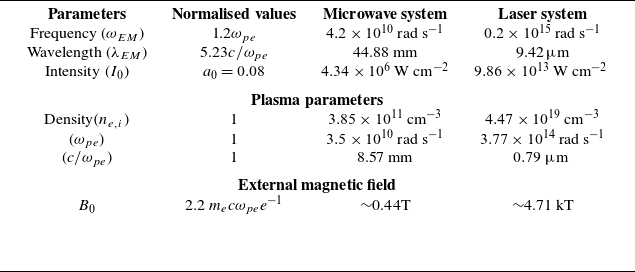
Simulation parameters are shown here in normalised as well as in corresponding SI units.

The chosen external magnetic field profile has a divergent nature from the centre line $y=110 l_N$
, which satisfies the required condition of
$y=110 l_N$
, which satisfies the required condition of $\boldsymbol{\nabla }\cdot\boldsymbol{B}_{ext}=0$
. Here, the value of parameter
$\boldsymbol{\nabla }\cdot\boldsymbol{B}_{ext}=0$
. Here, the value of parameter $(\delta =0.005)$
is chosen such that the associated gyrofrequency
$(\delta =0.005)$
is chosen such that the associated gyrofrequency $(\omega _{ce})$
due to the external magnetic field at the end of the target plasma stays larger than the incident EM wave frequency
$(\omega _{ce})$
due to the external magnetic field at the end of the target plasma stays larger than the incident EM wave frequency $[\omega _{ce}(x=160 l_N) \gt \omega _{EM}]$
, as shown in figure 1(c). This ensures that the group velocity of the EM wave within the plasma stays finite. The simulation run time was
$[\omega _{ce}(x=160 l_N) \gt \omega _{EM}]$
, as shown in figure 1(c). This ensures that the group velocity of the EM wave within the plasma stays finite. The simulation run time was $300\omega _{pe}^{-1}$
. During this time, the ion response is negligible compared with electrons and they merely act as a neutralising background (Dhalia et al. Reference Dhalia, Juneja and Das2024). Thus, the driving source of focusing for the incoming EM wave pulse is associated with the dynamics of the electrons, which, being lighter, respond at such a fast time scale. However, it should be noted that both the electron and ion dynamics have been considered in the simulation. The normalised vector potential of the EM wave is taken to be
$300\omega _{pe}^{-1}$
. During this time, the ion response is negligible compared with electrons and they merely act as a neutralising background (Dhalia et al. Reference Dhalia, Juneja and Das2024). Thus, the driving source of focusing for the incoming EM wave pulse is associated with the dynamics of the electrons, which, being lighter, respond at such a fast time scale. However, it should be noted that both the electron and ion dynamics have been considered in the simulation. The normalised vector potential of the EM wave is taken to be $a_0=0.08$
to stay within a non-relativistic regime. This intensity has been chosen such that the self-focusing due to relativistic nonlinearity can be avoided and we can have a direct comparison of unmagnetised and magnetised plasmas. The chosen normalised parameters can represent both a laser–plasma interaction as well as also microwave–plasma interaction by using appropriate normalisation factors. This is illustrated in table 1.
$a_0=0.08$
to stay within a non-relativistic regime. This intensity has been chosen such that the self-focusing due to relativistic nonlinearity can be avoided and we can have a direct comparison of unmagnetised and magnetised plasmas. The chosen normalised parameters can represent both a laser–plasma interaction as well as also microwave–plasma interaction by using appropriate normalisation factors. This is illustrated in table 1.
The microwave system features a pulse, high-power microwave of spot size 68.56 cm and frequency 6.7 GHz and power of approximately 16 GW incident on a plasma lens of height 171.4 cm and width of 85.7 cm (Nevins et al. Reference Nevins, Rognlien and Cohen1987; Allen et al. Reference Allen1994). The external magnetic field required here is of order $\sim\!0.44T$
or 4.4 kilogauss, which can be generated through a simple permanent magnet or an electromagnet. Similarly, a laser system will feature a moderate power 0.03 TW,
$\sim\!0.44T$
or 4.4 kilogauss, which can be generated through a simple permanent magnet or an electromagnet. Similarly, a laser system will feature a moderate power 0.03 TW, $\text{CO}_2$
laser of spot size 63.2
$\text{CO}_2$
laser of spot size 63.2 $\unicode{x03BC}$
m, incident on a plasma lens of height
$\unicode{x03BC}$
m, incident on a plasma lens of height $158$
$158$ $\unicode{x03BC}$
m and width
$\unicode{x03BC}$
m and width $79$
$79$ $\unicode{x03BC}$
m. The external magnetic field required is of order
$\unicode{x03BC}$
m. The external magnetic field required is of order $4.71 \,\text{kT}$
or 47.1 megagauss (Choudhary et al. Reference Choudhary, Goswami, Aparajit, Lad, Parab, Ved, Das and Kumar2025; Hao et al. Reference Hao, Tang, Arefiev, Kingham, Zhu, Shi and Zheng2025).
$4.71 \,\text{kT}$
or 47.1 megagauss (Choudhary et al. Reference Choudhary, Goswami, Aparajit, Lad, Parab, Ved, Das and Kumar2025; Hao et al. Reference Hao, Tang, Arefiev, Kingham, Zhu, Shi and Zheng2025).
Time evolution of Electromagnetic Field (EMF) energy density in the presence of (i) magnetised plasma lens (first row), (ii) unmagnetised plasma lens (second row) and (iii) magnetised plasma slab (third row) is presented.

3. Magnetic field-induced focusing
An incoming linearly polarised EM wave pulse typically breaks up into right (RCP) and left (LCP) circularly polarised waves while propagating parallel to an applied external magnetic field in a plasma medium. The separation occurs as the R and L-modes have different group velocities. This propagation is depicted in figure 2 by plotting the electromagnetic field energy density at various times as the pulse propagates through three different configurations of a finite-sized plasma target. The first corresponds to a target in the form of a plasma lens immersed in a magnetic field, the second has the same target profile, and no magnetic field is applied. The third corresponds to a plasma slab immersed in a magnetic field.
Figure demonstrates x-averaged EMF energy density with time and y-direction for (a) unmagnetised lens, (b) magnetised lens, (c) magnetised slab. Here, $t_1$
and
$t_1$
and $t_2$
denote times at which the wave pulse enters and leaves the plasma boundary, respectively.
$t_2$
denote times at which the wave pulse enters and leaves the plasma boundary, respectively.

At the vacuum plasma interface, the incoming wave pulse breaks into RCP and LCP wave pulse for the case of magnetised lens. Figure 2(b–d) shows that the spot size of slow RCP wave is decreasing. On the other hand the LCP wave pulse does not get focused and instead it shows divergence. In comparison, in the next row snapshots of the EMF energy density for an unmagnetised lens have also been shown at various times. The unmagnetised lens does not support slow and fast modes and merely follows the dispersion relation of unmagnetised underdense plasma. The EM wave passes through it and does not show focusing inside the plasma. The third case is of a magnetised plasma slab for which snapshots have been presented in the third row of figure 2. In this scenario, the wave again divides into slow RCP and fast LCP waves. However the observation indicates that the focusing of the RCP wave in this case compared with the first case is considerably weak.
Figure 3 shows the space–time ( $y$
vs.
$y$
vs. $t$
) plots of EMF energy averaged over the x-direction for all the three cases. Here,
$t$
) plots of EMF energy averaged over the x-direction for all the three cases. Here, $t_1$
and
$t_1$
and $t_2$
indicate the times when EM wave starts interacting with plasma and exits the plasma surface. It is evident from these plots that, for the unmagnetised case, the pulse EMF energy density was maximum around
$t_2$
indicate the times when EM wave starts interacting with plasma and exits the plasma surface. It is evident from these plots that, for the unmagnetised case, the pulse EMF energy density was maximum around $\sim\!(2\times 10^{-4} m_ec\omega _{pe}e^{-1})$
initially (before interaction) and it diverges in the transverse direction as it interacts with the plasma. Thus, no focusing has been observed in this scenario. On the other hand, for the case of the magnetised lens, laser spot size acquires a minimum spot and maximum EMF energy density
$\sim\!(2\times 10^{-4} m_ec\omega _{pe}e^{-1})$
initially (before interaction) and it diverges in the transverse direction as it interacts with the plasma. Thus, no focusing has been observed in this scenario. On the other hand, for the case of the magnetised lens, laser spot size acquires a minimum spot and maximum EMF energy density $\sim\!(4\times 10^{-4} m_ec\omega _{pe}e^{-1})$
around double it’s initial energy after the pulse has interacted with plasma at a time near
$\sim\!(4\times 10^{-4} m_ec\omega _{pe}e^{-1})$
around double it’s initial energy after the pulse has interacted with plasma at a time near $200 \omega _{pe}^{-1}$
. It is also interesting to notice that, afterwards, the pulse again defocuses and goes out of the simulation box. For the case of a plasma slab, again wave pulse acquires a minimum spot and the peak EMF energy density
$200 \omega _{pe}^{-1}$
. It is also interesting to notice that, afterwards, the pulse again defocuses and goes out of the simulation box. For the case of a plasma slab, again wave pulse acquires a minimum spot and the peak EMF energy density $\sim\!(3.5\times 10^{-4} m_ec\omega _{pe}e^{-1})$
. However, this focusing is not as tight as that for the plasma lens geometry of the target. Here, the spot size does not defocus after the pulse leaves the plasma boundary and remains constant with time.
$\sim\!(3.5\times 10^{-4} m_ec\omega _{pe}e^{-1})$
. However, this focusing is not as tight as that for the plasma lens geometry of the target. Here, the spot size does not defocus after the pulse leaves the plasma boundary and remains constant with time.
Figure shows the time evolution of full width at half maximum (FWHM) of incident wave with (a) unmagnetised lens, (b) magnetised lens, (c) magnetised slab.

Time evolution of net density fluctuation in electron density for three cases of magnetised lens, unmagnetised lens and magnetised slab.

We have also provided a comparison of the evolution of FWHM (full width at half-maximum) for each of the three cases. This has been plotted in figure 4. While for the unmagnetised lens the spot size shows divergence from the beginning itself, in the case of the magnetised lens, it gets focused by a factor of nearly $1/3.5$
and attains the value of
$1/3.5$
and attains the value of $(\sim\!20 c/\omega _{pe})$
. Thereafter, coming outside the plasma surface it again starts defocusing. For the slab geometry the focusing is weaker and it attains a value of
$(\sim\!20 c/\omega _{pe})$
. Thereafter, coming outside the plasma surface it again starts defocusing. For the slab geometry the focusing is weaker and it attains a value of $38 c/\omega _{pe}$
, which is a reduction by a factor of
$38 c/\omega _{pe}$
, which is a reduction by a factor of $1/2$
. It, therefore, appears that the convexity of the plasma profile plays a role in tighter focusing.
$1/2$
. It, therefore, appears that the convexity of the plasma profile plays a role in tighter focusing.
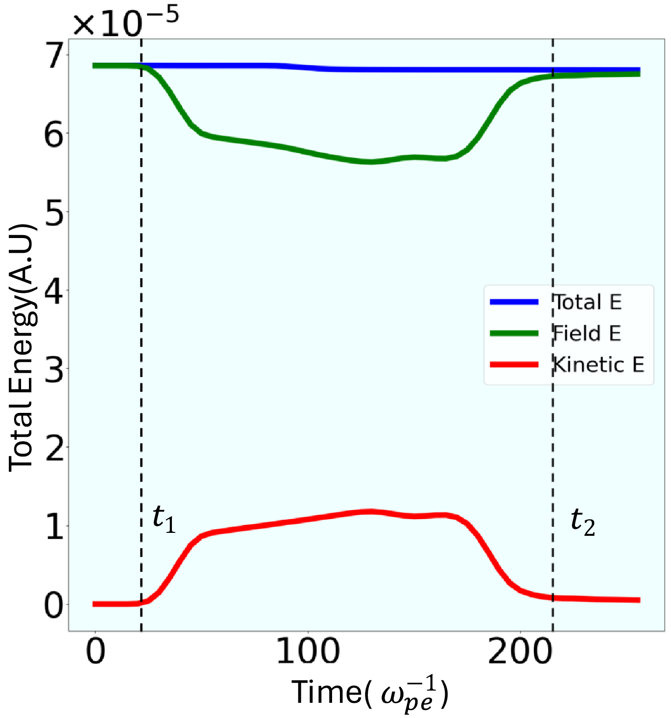
Time evolution of total energy, EMF energy and kinetic energy of electrons for the case of magnetic lens.

Figure 5 shows the comparison of plots for the electron density fluctuation for these three cases. It should be noted that a spatially inhomogeneous electron density distribution results for the two cases in which the magnetic field is present. The electron density bunches change the refractive index and are responsible for efficiently focusing the spot size of the EM wave pulse effectively in these cases.
These studies thus illustrate that both the shape of plasma and the profile of the magnetic field play crucial roles in EM wave pulse focusing. It should be noted that this is a novel approach. The focusing here does not require relativistic intensities of the EM wave pulse. In fact, even a moderately intense pulse can be focused at a desired location. Another important feature is that almost no energy is dissipated into the plasma during this interaction. Figure 6 shows the time evolution of the total energy, field energy and kinetic energy for the case of the magnetic lens. From this plot we observe that the total energy remains almost constant. There is a conversion from field to kinetic energy at the beginning of the interaction. Thereafter, however, the kinetic energy again converts back into field energy. We now try to understand the contrasting responses of focusing displayed by the LCP and the RCP EM waves in the next subsection.
Figures shows x-averaged time(t)–space (y) evolution of (a) LCP wave pulse, (b) RCP wave pulse in the presence of magnetised plasma lens.

(a) Shows the critical power of RCP and LCP waves in the magnetised plasma along the x-direction calculated with analytical expression (3.2), and (b) demonstrates the evolution of the beam waist $r_s$
of RCP and LCP waves in the magnetised plasma along the propagation direction from the analytical expression and simulation data.
$r_s$
of RCP and LCP waves in the magnetised plasma along the propagation direction from the analytical expression and simulation data.

3.1. Interpretation
We have also carried out simulations for an incident wave with a definite RCP and LCP form of polarisation. Here, the waves do not break up into two pulses as expected. However, only the RCP wave shows focusing whereas the wave pulse with LCP shows divergence, as seen from figure 7. This distinctive behaviours of focal spot evolution for the two polarisations are understood analytically by applying a local approximation to the theory put forth for the homogeneous magnetic field by Jha et al. (Reference Jha, Mishra, Upadhyaya and Raj2006, Reference Jha, Mishra, Upadhyay and Raj2007). In their study the source dependent expansion method (Esarey et al. Reference Esarey, Sprangle, Krall and Ting1997) is used to study the evolution of the laser spot. The expression for laser spot evolution in the presence of an axial magnetic field is given as
 \begin{equation} \frac {r_s^2}{r_0^2}= 1+ \left(1 -\frac {P}{P_{c}}\right)\frac {x^2}{X_R^2}. \end{equation}
Here, $r_s$
is the instantaneous beam waist and
$r_s$
is the instantaneous beam waist and $r_0$
is the initial beam waist. Also, P is the power of the EM wave pulse given as,
$r_0$
is the initial beam waist. Also, P is the power of the EM wave pulse given as, $P=(a_0^2r_0^2e^2/4k_0^2c^5m^2)$
and
$P=(a_0^2r_0^2e^2/4k_0^2c^5m^2)$
and
 \begin{equation} P_{c} = \frac {k_0^2c^5m^2 }{2k_{p0}^2e^2S}, \end{equation}
is the critical power required for self-focusing. Here, $k_0$
and
$k_0$
and $k_{p0}= 4\pi e^2 n_0/mc^2$
are wavenumbers of the EM wave and wavenumbers associated with the characteristic plasma frequency, respectively. The nonlinear parameter induced by the external magnetic field in the plasma for the RCP
$k_{p0}= 4\pi e^2 n_0/mc^2$
are wavenumbers of the EM wave and wavenumbers associated with the characteristic plasma frequency, respectively. The nonlinear parameter induced by the external magnetic field in the plasma for the RCP $(\sigma =1)$
and LCP
$(\sigma =1)$
and LCP $(\sigma =-1)$
waves is
$(\sigma =-1)$
waves is
 \begin{equation} S=\frac {\omega _{EM}^4( \omega _{EM}+\sigma \omega _{ce})^4}{(\omega _{EM}^2-\omega _{ce}^2)^4}. \end{equation}
Here, $\omega _{ce}=eB_0/m$
and
$\omega _{ce}=eB_0/m$
and $X_R=(k_0^2r_0^2/2)$
is the Rayleigh length. We have plotted the critical power
$X_R=(k_0^2r_0^2/2)$
is the Rayleigh length. We have plotted the critical power $P_c$
with the help of (3.2) and (3.3) along the axis for the changing magnetic field in our system. The variation of the critical power with distance
$P_c$
with the help of (3.2) and (3.3) along the axis for the changing magnetic field in our system. The variation of the critical power with distance $x$
is shown in figure 8
$x$
is shown in figure 8 $(a)$
. It should be noted from the figure that the value of critical power is very high for the LCP wave, whereas for the RCP wave it is quite low. The power of our chosen EM wave pulse exceeds the critical power for the RCP wave, and hence focusing is observed.
$(a)$
. It should be noted from the figure that the value of critical power is very high for the LCP wave, whereas for the RCP wave it is quite low. The power of our chosen EM wave pulse exceeds the critical power for the RCP wave, and hence focusing is observed.
The role of the inhomogeneous magnetic field and the plasma profile provides a much better focusing than what is predicted by the analytical theory of a homogeneous magnetic field. This is illustrated by figure 8(b) for which the beam waist evolution in space is shown for both LCP and RCP waves through simulation and analytical estimate.
(a) Shows the FWHM of the incident EM wave for four different curvatures of a convex plasma geometry and they are fitted with a second-order polynomial $a_2x^2+a_1x+a_0$
. In (b) we plot the coefficient
$a_2x^2+a_1x+a_0$
. In (b) we plot the coefficient $a_2$
with respect to curvature parameter
$a_2$
with respect to curvature parameter $c_0$
.
$c_0$
.

3.2. Effect of lens curvature on focusing
We established in the preceding section that incident RCP wave pulses are strongly focused under the magnetised plasma lens. Here, we want to demonstrate the effect of plasma lens curvature on magnetic field-induced focusing. For this, we have incident RCP waves on five distinct shapes corresponding to the curvature parameters $c_0=0,0.001,0.003,0.005,0.007$
of plasma and we kept the magnetic field profile
$c_0=0,0.001,0.003,0.005,0.007$
of plasma and we kept the magnetic field profile $(\delta =0.005)$
constant in all five cases. Figure 9(a) shows the evolution of the beam waist
$(\delta =0.005)$
constant in all five cases. Figure 9(a) shows the evolution of the beam waist $r_s$
of an RCP wave pulse through several plasma lenses. This effectively demonstrates that increasing the curvature of the plasma lens improves focusing. The curves fit well on a second-degree polynomial (
$r_s$
of an RCP wave pulse through several plasma lenses. This effectively demonstrates that increasing the curvature of the plasma lens improves focusing. The curves fit well on a second-degree polynomial ( $a_2x^2+a_1x+a_0$
) within the plasma boundary. In the case of
$a_2x^2+a_1x+a_0$
) within the plasma boundary. In the case of $c_0=0.007$
, a minimal spot is observed within the plasma lens, and spot size decreases in a quadratic pattern. It is also worth noting that, for a slab geometry
$c_0=0.007$
, a minimal spot is observed within the plasma lens, and spot size decreases in a quadratic pattern. It is also worth noting that, for a slab geometry $(c_0=0)$
, focusing is lowest and the spot size decreases in a linear fashion. Figure 9(b) demonstrates that, as the curvature
$(c_0=0)$
, focusing is lowest and the spot size decreases in a linear fashion. Figure 9(b) demonstrates that, as the curvature $c_0$
grows, so does the coefficient
$c_0$
grows, so does the coefficient $a_2$
in a linear fashion. Obviously, the curvature parameter should not exceed a particular limit so that the lens height is comparable to or less than the laser spot size; otherwise, spherical aberration will impede the focusing. This concludes that the curvature of the plasma lens provides additional focusing on top of magnetic field-induced focusing.
$a_2$
in a linear fashion. Obviously, the curvature parameter should not exceed a particular limit so that the lens height is comparable to or less than the laser spot size; otherwise, spherical aberration will impede the focusing. This concludes that the curvature of the plasma lens provides additional focusing on top of magnetic field-induced focusing.
4. Magnetic field-induced focused electron beam generation
In the previous section, it has been shown that the RCP wave gets efficiently focused with the help of a magnetised plasma lens. We show here that, by appropriately tailoring the magnetic field profile with the help of the parameter $\delta$
, we can produce an energetic electron beam. We kept the curvature parameter
$\delta$
, we can produce an energetic electron beam. We kept the curvature parameter $ c_0 = 0.005$
for the lens profile. This happens when the magnetic field profile is tailored to have the Electron cyclotron resonance (ECR) lie within the plasma. In our studies we achieve this by choosing the following form of the magnetic field profile with the choice of
$ c_0 = 0.005$
for the lens profile. This happens when the magnetic field profile is tailored to have the Electron cyclotron resonance (ECR) lie within the plasma. In our studies we achieve this by choosing the following form of the magnetic field profile with the choice of $\delta = 0.02$
:
$\delta = 0.02$
:
 \begin{equation} \boldsymbol{B}_{N,ext}= [2.2 -0.02(x-110)]\hat {i}+ [0.02(y-110)]\hat {j}. \end{equation}
Under the application of this profile of the magnetic field, the ECR condition is met at the edge of the plasma lens. This is shown in figure 10. Here, the red dot shows the ECR point where the cyclotron frequency matches the EM wave frequency.
Figure demonstrates the plasma lens $(c_0=0.005)$
situated in a high gradient external magnetic field. The ECR point represent the location at plasma edge where the EM wave frequency matches the electron cyclotron frequency.
$(c_0=0.005)$
situated in a high gradient external magnetic field. The ECR point represent the location at plasma edge where the EM wave frequency matches the electron cyclotron frequency.

Figure shows space–time plots for EMF energy. Panels show $(a)$
y–t plot averaged over the x-dimension;
$(a)$
y–t plot averaged over the x-dimension; $(b)$
t–x plot averaged over the y-dimension;
$(b)$
t–x plot averaged over the y-dimension; $(c)$
t–x plot of kinetic energy averaged over the y-dimension.
$(c)$
t–x plot of kinetic energy averaged over the y-dimension.

The high gradient magnetic field focuses the wave pulse very rapidly and thus a RCP wave pulse with minimum spot size is achieved at the plasma edge. The ECR condition then results in the dumping of the EM wave energy to the electrons very rapidly. This is consistent with one of our earlier studies (Dhalia et al. Reference Dhalia, Juneja and Das2024), where we have shown the conversion of EM field energy to electron kinetic energy at the ECR point. This has also been illustrated from figure 11. In $(a)$
we depict the EMF energy as a function of time and the transverse dimension
$(a)$
we depict the EMF energy as a function of time and the transverse dimension $y$
. We have averaged it over the
$y$
. We have averaged it over the $x$
dimension here. It should be noted that it maximises when the pulse gets focused inside the plasma. However, at a later stage the EMF energy gets weakened. This happens as the EMF energy gets transferred to the electron kinetic energy at the resonance point. This interdependence is clearly depicted in
$x$
dimension here. It should be noted that it maximises when the pulse gets focused inside the plasma. However, at a later stage the EMF energy gets weakened. This happens as the EMF energy gets transferred to the electron kinetic energy at the resonance point. This interdependence is clearly depicted in $(b)$
and
$(b)$
and $(c)$
. Here, we have shown the EMF energy and the electron kinetic energy by colour plots as a function of
$(c)$
. Here, we have shown the EMF energy and the electron kinetic energy by colour plots as a function of $x$
and
$x$
and $t$
. It should be noted that the EMF energy gets weaker at the specific location
$t$
. It should be noted that the EMF energy gets weaker at the specific location $x = x_{ECR}$
, which is the resonance point. Exactly at this location the electrons acquire a huge kinetic energy.
$x = x_{ECR}$
, which is the resonance point. Exactly at this location the electrons acquire a huge kinetic energy.
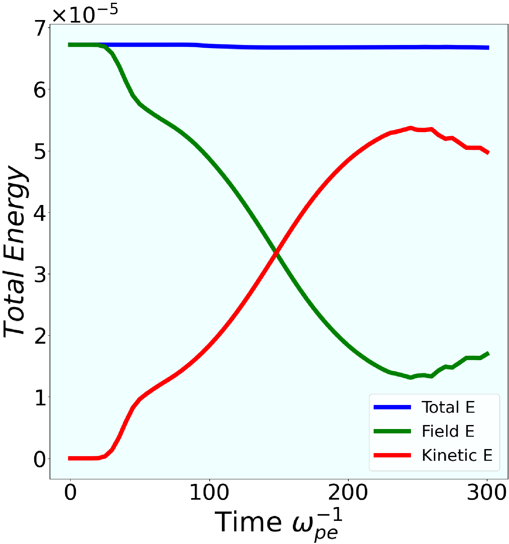
Time evolution of total energy, EMF energy and kinetic energy of electrons for the case of high magnetic field gradient.

Figure 12 also shows the energy evolution with time. The graph shows that nearly $80\,\%$
of the pulse energy has been transferred to electrons. The particle trajectories of these randomly chosen 2000 electrons from the focal spot location are shown in figure 13(a). Panel (a) shows the particle trajectory with time shown on the colorbar. The transverse dimension of the emerging beam is approximately
$80\,\%$
of the pulse energy has been transferred to electrons. The particle trajectories of these randomly chosen 2000 electrons from the focal spot location are shown in figure 13(a). Panel (a) shows the particle trajectory with time shown on the colorbar. The transverse dimension of the emerging beam is approximately $5l_N$
. These ejected particles strongly follow the external magnetic field direction and divide into two electron beams and propagate away.
$5l_N$
. These ejected particles strongly follow the external magnetic field direction and divide into two electron beams and propagate away.
Figure illustrates (a) the trajectory of randomly chosen 2000 electrons for colour axis with respect to time (until $600\omega _{pe}^{-1}$
) and angular distribution of electrons at times (b)
$600\omega _{pe}^{-1}$
) and angular distribution of electrons at times (b) $300\omega _{pe}^{-1}$
and (c)
$300\omega _{pe}^{-1}$
and (c) $450\omega _{pe}^{-1}$
.
$450\omega _{pe}^{-1}$
.

Figure 13(b,c) shows the angular distribution of these particle at times $300 \omega _{pe}^{-1}$
and
$300 \omega _{pe}^{-1}$
and $450 \omega _{pe}^{-1}$
with the colorbar showing the electron counts and the radius of the circle represents the energy in MeV. At
$450 \omega _{pe}^{-1}$
with the colorbar showing the electron counts and the radius of the circle represents the energy in MeV. At $300 \omega _{pe}^{-1}$
, these ejected electrons have almost a directional distribution and are directed along the laser axis. Later in time, they diverge and spread along the perpendicular direction of the laser axis due to the external magnetic field present in the vacuum. Maximum electron energy is approximately
$300 \omega _{pe}^{-1}$
, these ejected electrons have almost a directional distribution and are directed along the laser axis. Later in time, they diverge and spread along the perpendicular direction of the laser axis due to the external magnetic field present in the vacuum. Maximum electron energy is approximately $E\sim 0.78 m_ec^2 =0.4\, \text{MeV}$
against the incident EM wave of the normalised vector potential
$E\sim 0.78 m_ec^2 =0.4\, \text{MeV}$
against the incident EM wave of the normalised vector potential $a_0=0.08$
.
$a_0=0.08$
.
This is an efficient mechanism to produce a highly focused electron beam through the magnetic-field-induced-focusing of an EM wave. Thus, appropriately tailored parameters can be used in experiments for collimated electron beam generation. We have chosen a linearly decreasing type of external magnetic field throughout our study. However, the effect of different magnetic field profiles while keep the curvature parameter fixed has also been discussed in Appendix A.
5. Experimental challenges and practical feasibility
The proposed scheme of the magnetised plasma lens for infrared laser $(\text{CO}_2 \text{ laser } (\lambda =9.42$ $\unicode{x03BC}$
m) is, no doubt, quite a challenge in terms of practical feasibility. However, the recent pace of technological advancement does seem to show promise in overcoming those difficulties. First of all, the generation of a low-density convex-shaped plasma lens
$\unicode{x03BC}$
m) is, no doubt, quite a challenge in terms of practical feasibility. However, the recent pace of technological advancement does seem to show promise in overcoming those difficulties. First of all, the generation of a low-density convex-shaped plasma lens $n_e\sim 5\times 10^{19}\, \text{cm}^{-3}$
. The low-density foam targets have a typical density in this range, approximately
$n_e\sim 5\times 10^{19}\, \text{cm}^{-3}$
. The low-density foam targets have a typical density in this range, approximately $\sim\!10^{20} {-}10^{22}$
(Borisenko et al. Reference Borisenko, Khalenkov, Kmetik, Limpouch, Merkuliev and Pimenov2007; Liu et al. Reference Liu, Campbell, Stein, Jiang, Hund and Lu2018). The recent work by Rosmej et al. has used an advanced plasma target with just 10 times higher density
$\sim\!10^{20} {-}10^{22}$
(Borisenko et al. Reference Borisenko, Khalenkov, Kmetik, Limpouch, Merkuliev and Pimenov2007; Liu et al. Reference Liu, Campbell, Stein, Jiang, Hund and Lu2018). The recent work by Rosmej et al. has used an advanced plasma target with just 10 times higher density $(6.5\times 10^{20}\,\text{cm}^{-3})$
, made up of pre-ionised aerogel foam (Rosmej et al. Reference Rosmej2025). Thus, in the near future, with the advancement in target fabrication methods, shaped plasma targets with such a low density will be possible. The second demand is the requirement of a strong magnetic field. We have used a diverging magnetic field profile, which is similar to what a permanent magnet produces in its vicinity. Recently, high magnetic fields (
$(6.5\times 10^{20}\,\text{cm}^{-3})$
, made up of pre-ionised aerogel foam (Rosmej et al. Reference Rosmej2025). Thus, in the near future, with the advancement in target fabrication methods, shaped plasma targets with such a low density will be possible. The second demand is the requirement of a strong magnetic field. We have used a diverging magnetic field profile, which is similar to what a permanent magnet produces in its vicinity. Recently, high magnetic fields ( $\sim\!kT$
) have been generated over
$\sim\!kT$
) have been generated over $\sim\!nano$
second time scales within experimental environments (Nakamura et al. Reference Nakamura, Ikeda, Sawabe, Matsuda and Takeyama2018; Choudhary et al. Reference Choudhary, Goswami, Aparajit, Lad, Parab, Ved, Das and Kumar2025; Hao et al. Reference Hao, Tang, Arefiev, Kingham, Zhu, Shi and Zheng2025). The required external magnetic field needs only up to a few picoseconds to self-focus the laser pulse under these conditions. Thus, we believe that use of the magnetised plasma lens would be experimentally feasible and needed in achieving extreme intensities.
$\sim\!nano$
second time scales within experimental environments (Nakamura et al. Reference Nakamura, Ikeda, Sawabe, Matsuda and Takeyama2018; Choudhary et al. Reference Choudhary, Goswami, Aparajit, Lad, Parab, Ved, Das and Kumar2025; Hao et al. Reference Hao, Tang, Arefiev, Kingham, Zhu, Shi and Zheng2025). The required external magnetic field needs only up to a few picoseconds to self-focus the laser pulse under these conditions. Thus, we believe that use of the magnetised plasma lens would be experimentally feasible and needed in achieving extreme intensities.
6. Summary
The above discussion shows that when a linearly polarised EM wave pulse propagates through an underdense homogeneous plasma lens embedded in a slowly diverging type of external magnetic field, it divides into RCP and LCP wave pulses, and the spot size of the RCP wave pulse reduces to a minimum size through self-focusing. The electrons in the plasma under the influence of an electromagnetic wave drift along the external magnetic field direction, causing a density compression and depression, which modifies the refractive index of the plasma, and the EM wave focuses along the propagation axis. Our analysis has shown that focusing is also dependent on the shape of the plasma. With just a 79 $\unicode{x03BC}$
m thin shaped plasma lens
$\unicode{x03BC}$
m thin shaped plasma lens $(c_0=0.005)$
, magnetic field-induced focusing reduces the spot size of an incident RCP wave by almost
$(c_0=0.005)$
, magnetic field-induced focusing reduces the spot size of an incident RCP wave by almost $\sim\!1/3.5$
and increases the intensity by almost three times. One of the main advantages of using an underdense magnetic lens is that energy loss in the plasma could be minimal, and a focused wave pulse can be obtained. Further, it is also established that, by increasing the gradient of the magnetic field, a wave pulse can be focused inside the plasma at ECR resonance and can generate a strong, collimated electron beam.
$\sim\!1/3.5$
and increases the intensity by almost three times. One of the main advantages of using an underdense magnetic lens is that energy loss in the plasma could be minimal, and a focused wave pulse can be obtained. Further, it is also established that, by increasing the gradient of the magnetic field, a wave pulse can be focused inside the plasma at ECR resonance and can generate a strong, collimated electron beam.
Contrary to earlier studies with relativistic focusing, here, we demonstrate that an actual curved plasma lens in the presence of a strong magnetic field can focus the non-relativistic laser pulse outside the plasma (Hora Reference Hora1975; Ren et al. Reference Ren, Duda, Hemker, Mori, Katsouleas, Antonsen and Mora2001; Sprangle, Tang & Esarey Reference Sprangle, Tang and Esarey2007). Thus, low-intensity, wider spot size, high-energy (Joule) level pulses can be effectively focused at much higher intensities with the proposed scheme. In addition to the transverse focusing shown here by the RCP laser pulse, it would be interesting to study the effect of a chirped laser profile. A study based on this is also underway to see the simultaneous effects of pulse compression and focusing to reach extreme intensities using magnetised plasma lenses. The theory can find applications in the focusing of strong intense lasers and industrial plasma as well as particle accelerator schemes. Magnetic field-induced focusing can play a major role in inertial confinement fusion as well.
Acknowledgements
The authors would like to thank the IIT Delhi HPC facility for computational resources.
Editor Luís O. Silva thanks the referees for their advice in evaluating this article.
Funding
The authors would like to acknowledge the OSIRIS Consortium, consisting of UCLA and IST (Lisbon, Portugal), for providing access to the OSIRIS 4.0 framework, which is the work supported by the NSF ACI-1339893. A.D. acknowledges support from the Anusandhan National Research Foundation (ANRF) of the Government of India through core grant CRG/2022/002782 as well as her J C Bose Fellowship grant JCB/2017/000055. T.D. also wishes to thank the Council for Scientific and Industrial Research (Grant No. 09/086/(1489)/2021-EMR-I) for funding the research.
Declaration of interest
The authors report no conflict of interest.
Author contributions
T.D. and A.D. planned the research; T.D. derived the theory and performed the simulations; T.D. and R.J. analysed the results; T.D. and A.D. interpreted the results; T.D. and A.D. wrote the manuscript; A.D. supervised the research.
Data availability
The data that support the findings of this study are available from the corresponding authors upon reasonable request.
Appendix A. Laser pulse focusing with different magnetic field profiles
We have shown results so far with a linear decreasing diverging external magnetic field profile represented by (2.2) inspired from magnetic field lines of a permanent magnet. However, we have also performed simulations with other magnetic field profiles for an incident RCP laser of frequency $(\omega _{EM}=1.2\omega _{pe})$
. For an exponentially decaying magnetic field profile, we simulated two cases:
$(\omega _{EM}=1.2\omega _{pe})$
. For an exponentially decaying magnetic field profile, we simulated two cases:
-
(i)
(A1) \begin{align} \boldsymbol{B}_{N,ext} & = 1.9 \cdot [\text{exp}(-(x-160)/160)\hat {i}\nonumber\\& \quad + ((y-160)/160) \cdot \text{exp}(-(x-160)/160)\hat {j}] \end{align}
-
(ii)
(A2)
\begin{align} \boldsymbol{B}_{N,ext} & =2.4 \cdot [\text{exp}(-(x-110)/110)\hat {i}\nonumber\\& \quad + ((y-110)/110) \cdot \text{exp}(-(x-110)/110)\hat {j}] \end{align}


Panels $(a,\!b,\!c)$
show the time evolution of EMF energy density averaged along the x-direction under various applied external magnetic field profiles represented by (A1), (A2) and (A3), respectively. The variation along the x-direction of the
$(a,\!b,\!c)$
show the time evolution of EMF energy density averaged along the x-direction under various applied external magnetic field profiles represented by (A1), (A2) and (A3), respectively. The variation along the x-direction of the $B_x$
component has also been plotted, as shown in
$B_x$
component has also been plotted, as shown in $(d)$
.
$(d)$
.

To consider the effect of only the shape of the plasma lens, a simulation with a constant magnetic field profile has also been performed
 \begin{equation} \boldsymbol{B}_{N,ext}=[2.0 ]\hat {i} .\end{equation}
Figure 14 $(a,\!b,\!c)$
shows the time evolution of EMF energy density under these three magnetic field profiles. This clearly demonstrates that the focusing power of the laser pulse increases with the slope of the magnetic field profile
$(a,\!b,\!c)$
shows the time evolution of EMF energy density under these three magnetic field profiles. This clearly demonstrates that the focusing power of the laser pulse increases with the slope of the magnetic field profile $(B_x)$
. For a constant magnetic field (profile-3), the laser pulse is just focused outside of the plasma, purely due to the convex shape of the plasma, which bends the incoming laser pulse and converges at the focal point of the magnetised plasma lens. Thus, we would like to emphasise that for magnetic field-induced focusing is possible with any type of diverging or constant magnetic field profile applied parallel to the laser propagation and convex plasma lens axis, as long as it satisfies the condition
$(B_x)$
. For a constant magnetic field (profile-3), the laser pulse is just focused outside of the plasma, purely due to the convex shape of the plasma, which bends the incoming laser pulse and converges at the focal point of the magnetised plasma lens. Thus, we would like to emphasise that for magnetic field-induced focusing is possible with any type of diverging or constant magnetic field profile applied parallel to the laser propagation and convex plasma lens axis, as long as it satisfies the condition $(\omega _{ce}\gt \omega _l)$
during the laser interaction.
$(\omega _{ce}\gt \omega _l)$
during the laser interaction.


 Open access