


Introduction
The field of wireless communication has been undergoing a revolutionary change over the last two decades. Invention of mobile phones, wireless local area networks (WLANs), wireless local loops (WLLs), Bluetooth technology, and radio-frequency identification (RFID) devices are only a few to name which can be attributed to this fact. One of the key components of any wireless communication is the antenna. The emerging-market trend of wireless devices is moving toward a nature where they can be used anywhere with similar efficiency. Moreover, the rapid expansion of the wireless communication industry has created a need for connectivity among various wireless devices thus giving freedom from the cable connections. Thus, with the advent of multifunctional wireless gadgets demand for low power, portable, wideband, multiband antennas have increased in leaps and bounds in any mobile communication system. Immense uses of wireless gadgets like cordless phones, Wi-Fi, Bluetooth, WLANs, WLLs, and wireless computer networks have become an essential part of everyday life all over the world, especially in urban areas. Two of the indispensable components of this world of wireless communication are wideband antennas and multi-frequency antennas. As these antennas operate over a wide frequency range or in several frequency bands, the number of antennas required to design a particular system is reduced. Hence the systems become smaller in size, light in weight, and compact in nature. The journey first started with the invention of broadband antennas. Gradually due to applications in various fields of wireless communication people showed interest in multi-frequency antennas also. Finally, the two goals were merged to design wideband multi-frequency antennas which yield benefits of both structures.
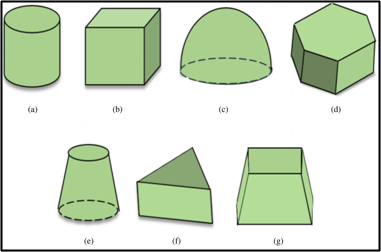
In the last four decades, two classes of novel antennas namely, microstrip patch antennas and dielectric resonator antennas (DRAs) have been investigated and extensively reported on. Both types of antennas are extensively used for the development of modern wireless communication. But as we moved to the higher range of microwave frequencies (100–300 GHz) it was observed that ohmic loss in microstrip antennas increases significantly. Moreover, the amount of power coupled to surface waves also increases. As a result, the efficiency of the antenna diminished significantly. On the other hand, DRAs have some advantages like low loss, low cost, lightweight, small size, high radiation efficiency, etc. compared to microstrip antennas. All these features have made DRAs more suitable for wireless applications. The resonant frequency of the antenna is primarily determined by the dimensions and dielectric constant εr of the resonator block. The radiation patterns are highly dependent on the mode of excitation of the DRA and the feed structure. Generally, a DRA radiates like a magnetic dipole when excited in fundamental mode. Popular feed structures like a coaxial probe, microstrip line, slots, and coplanar waveguide (CPW) are commonly used for the excitation of a DRA. Various shapes of DRAs are shown in Fig. 1.
Various shapes of DRAs: (a) cylindrical, (b) rectangular, (c) hemispherical, (d) hexagonal, (e) conical, (f) triangular, (g) trapezoidal. [Reproduced from Meher, et al., A chronological review of circularly polarized dielectric resonator antenna: design and developments. International Journal of RF and Microwave Computer-Aided Engineering 31 (2021) 22589:1–26.]
To enhance different performance parameters like gain, bandwidth, etc., special feed structures like a conformal strip with a parasitic patch, a special-shaped parasitic patch, and an open half-loop antenna are being used to excite a DRA. Different techniques like stacked resonators, hybrid resonators, the air gap between the substrate and the resonator, parasitic resonators along with the principle resonator, etc. have been adopted by many researchers to produce wideband, multiband DRAs. With innovation and imagination supported by reliable technical theories, the world of DRAs is now rich and varied.
The main advantages and disadvantages of DRAs are listed below by which they have surpassed the conventional microstrip antennas in many aspects.
Advantages of DRAs
• The size of a DR is proportional to λ/εr 1/2 where λ is the wavelength at the resonant frequency and εr is the dielectric constant of the resonator. Hence the size of the DR has reduced compared to its contemporary counterparts like microstrip antennas for the same design frequency.
• The size and bandwidth of the DR can be easily controlled by the proper choice of εr (ranging from 4 to 100). Compact sized DR can be designed with a high permittivity material whereas a wideband is achievable with a low permittivity material. This feature brings high design flexibility.
• As the frequency range of interest gradually moves upward to the millimeter range, the efficiency of any metallic antenna decreases significantly. This occurs due to the conductor loss which becomes severe at such high frequency. Moreover, power coupled to surface waves also increases. Conversely, the only loss for a DRA is due to the imperfect dielectric material, which can be very small in practice. As a result, very high radiation efficiency can be obtained in DRAs.
• DRAs have been designed to operate over a wide frequency range from 55 MHz to 94 GHz which is an enormous coverage compared with other existing antennas in the literature.
• Various shapes of DRs can be used such as rectangular, hemispherical, cylindrical, etc. which provides design flexibility.
• DRAs can be excited by many existing feed structures like slots, probes, CPWs, dielectric image guides, etc. This makes DR amenable to integration with existing technologies.
• DRAs of different shapes can be made to radiate in different modes which have diverse radiation patterns like broadside or conical with high radiation efficiency. As a result, DRAs find applications in various fields of wireless communication.
Disadvantages of DRAs
With many advantages of DRAs being mentioned, certain difficulties that are associated with the practical implementation of a DRA should also be noted:
• The materials of the resonators are generally very hard and it becomes difficult to machine a resonator to the proper shape and size.
• The resonant frequency is very sensitive to the dimensions of a DRA and it often requires the usage of CNC machines and additional care.
• Most of the DR materials having some particular value of permittivity are not easily available in nature. The materials need to be developed industrially maintaining homogeneity throughout the DR block.
• The radiation parameters and gain of the antenna depend on both the DR and the relative position of the DR concerning the feed structure. Hence precision must be maintained while mounting the DR block on or around the feed structure mechanically.
The goal of the work
The main motivation and goal for this work are to discuss the necessity and different applications of wideband and multiband of DRAs. With wireless technology rapidly expanding, the need for wideband as well as multi-frequency antennas is also growing at a fast pace. Researchers are looking forward to multi-frequency antennas and wideband antennas with properties like reduced size, moderate gain in the defined range of frequencies, etc. From the very early days of antenna engineering, it has been a constant challenge to increase the impedance bandwidth of an antenna along with miniaturization of the same. A DRA is equipped to fulfill both the requirements to a great extent. Critical observation reveals that in microstrip antennas with an increase in relative permittivity the size of the antenna decreases along with a decrease in resonant frequency, but its radiation efficiency also gets degraded. Since the resonant frequency of a DRA is inversely proportional to the square root of its permittivity, the size of the DR is reduced compared to its contemporary counterparts like microstrip antennas for the same design frequency, but without any degradation in radiation efficiency. Moreover, various techniques like lowering of Q (quality factor) or coupling of two or more resonant modes have also been adopted and reported by researchers in which DRAs are wideband. A single antenna then can be used for various applications and a communication system then can be compact and in reduced size. For the same reasons, multi-frequency antennas have also become popular in wireless communication systems. The most commonly used bands in wireless communications are the first (2.4–2.5 GHz) and second (5.725–5.875 GHz) ISM bands. The 2.4 GHz frequency band finds extensive use in applications like cordless phones, WLANs, WLLs, wireless computer networks, Bluetooth technology, RFID devices, etc. The 5.8 GHz band is used in various applications like intelligent transport systems which include road to vehicle communication and inter-vehicle Communication systems satellite communication, Wi-Fi, and cordless phones, WLANs, WiMAX, etc. All of these applications use multi-frequency antennas in a practical scenario. Hence various technologies have been adopted to design antennas with multiple resonances.
In this review work our goal is to provide a detailed review on broadband DRAs, then follow the roadmap of various works done to design multi-frequency DRAs, and finally discuss a few works that have been done to invent wide dual-band antennas in four different consecutive sections. The work has been done based on DRAs with a single dielectric resonator (DR), DRAs with multi DRs, and hybrid DRAs. Different subsections have been included under each section to have a detailed insight into the various techniques that have been adapted so far. The work done in the last few years are presented in a nutshell in the last section to give a quick overview of the type of investigations that have been carried out to achieve either broadband or multi-frequency or both. The review work will be extremely helpful to develop the initial idea about DRAs. Moreover, it will also throw light on different techniques which have been adopted so far for developing broadband and multi-frequency DRAs.
Broad classification of wideband antennas
This paper presents a review of a significant number of works done on DRAs from the very beginning to date. Demand for this type of antenna has increased by leaps and bounds and this can be verified by observing numerous papers published in the last few decades. A substantial number of articles has been published on DRAs [Reference Petosa and Ittipiboon1], but the demand and popularity of this type of antenna are undeniable. Various techniques have been adopted so far to enhance the bandwidth of DRAs. Some of the designs have simple structures whereas some have quite complex structures and classification of all of these can be done using various principles. As a DR is the primary component in the antenna structures three categories can be listed if broad classifications of these methods are done on the number of DRs used, namely
• DRAs with a single DR,
• DRAs with multi-DRs,
• Hybrid DRAs.
DRAs with single DR
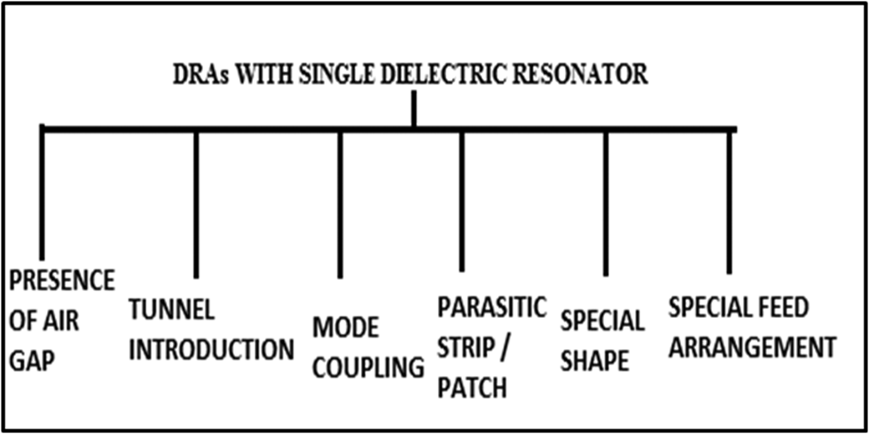
Various techniques that have been adopted to design a wideband antenna with a single DR structure are shown in Fig. 2.
Different techniques adapted for a single DR.
Presence of air gap between the ground plane and DR
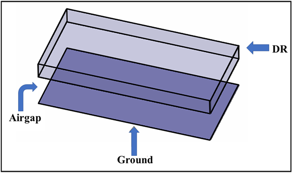
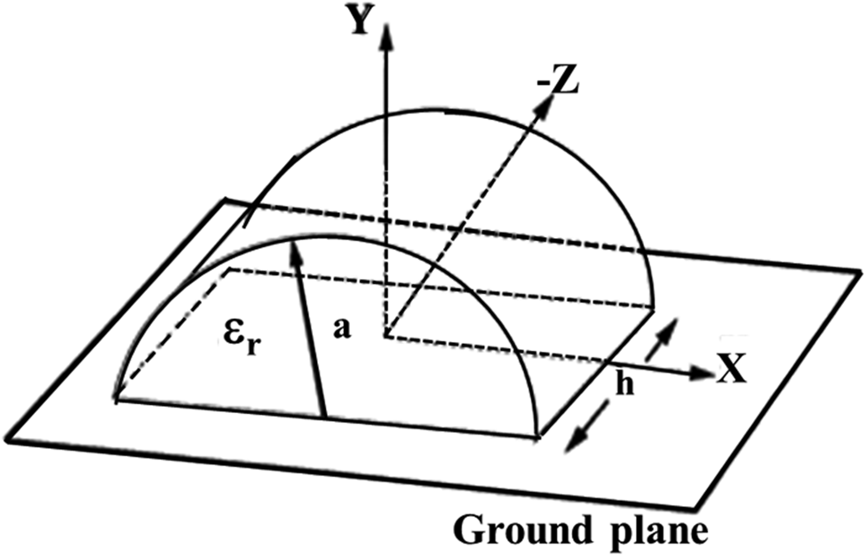
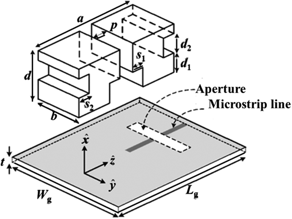
In 1993 Wong et al. used a hemispherical DR antenna of hemispherical shape with an air gap between DR and ground plane as shown in Fig. 3 [Reference Wong, Cheng and Chen2]. The structure was fed by the very popular coaxial probe. The main target was to reduce the effective permittivity, thereby reducing Q (quality factor) and enhancing the bandwidth. Numerical analysis using Green's function showed bandwidth was doubled (24%) as compared to the structure without any air gap. Much later in 2010, Weng et al. carried out numerical and experimental investigations using a similar structure [Reference Weng, Wang, Jiao and Zhang3]. Here the rectangular DRA was moved from the ground thus introducing an air dielectric between itself and the ground. The structure was slot fed and parametric studies showed a very good bandwidth enhancement (61%).
Structure of DR and ground with an air gap between the two. [Reproduced from Z. Weng et al., Wideband rectangular dielectric resonator antenna (DRA) with slot fed design, Progress in Electromagnetics Research Letters 16 (2010) 181–190.]
Removing portions/introducing tunnel within the DR
Removing a portion of DR also affects the Q (quality factor) of the antenna structure and this concept was followed by Ittipiboon et al. in 1996 [Reference Ittipiboon, Petosa, Roscoe and Cuhaci4]. They experimented with a slot-coupled microstrip line-fed rectangular DRA and the center portion of the antenna was removed. The effective ring structure of the antenna achieved a 28% bandwidth.
The same drive to reduce Q and enhance the bandwidth led to the invention of a DRA with a horizontal tunnel within the resonator (see Fig. 4). The antenna was excited by an aperture-coupled microstrip line and the investigation was carried out by Chang et al. in 2008 [Reference Chang, Huang, Su and Kiang5]. In this case, ≈20% bandwidth was obtained.
Front view of a block of rectangular DR with a tunnel within it. [Reproduced from Chang et al., Wideband dielectric resonator antenna with a tunnel. IEEE Antennas and Wireless Propagation Letters, 7 (2008) 275–278.]

Mode coupling
Another technique that was adopted by the researchers was to couple two modes or two resonant frequencies together to enhance the bandwidth. Chair et al. proposed very simple cylindrical DRAs fed by either a probe or aperture-coupled microstrip line [Reference Chair, Kishk and Lee6]. Dual modes were generated and merged by properly choosing the aspect ratio of the antenna. Nearly 27% bandwidth was achieved in this case. De Young and Long pursued a similar type of work with both rectangular and cylindrical structures and achieved 44% bandwidth in both cases [Reference De Young and Long7].
Two resonant frequencies were also merged by placing a low-profile DR near a microstrip-fed inverted-L monopole [Reference Gao, Popov and Ooi8]. The antenna was designed without any ground plane and a bandwidth of 28% was achieved in this case. In some works, the DRs were coated either with dielectric [Reference Chen, Su, Wong and Leung9] or with metal [Reference Chang and Kiang10] to merge two resonant modes and hence achieve a broad bandwidth.
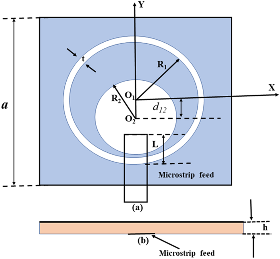
Another wideband rectangular dielectric resonator antenna (RDRA) was reported by Dhar et al. in 2011 (see Fig. 5). The rectangular DRA was rotated by 45° concerning CPW-fed non-resonating inductive slot and orthogonal modes were generated which were merged to give a wide bandwidth of 14.3% [Reference Dhar, Ghatak, Gupta and Poddar11].
Geometry of the rotated DRA. [Reproduced from Dhar et al. International conference on information and electronics engineering, Singapore, Vol. 6 (2011) 91–94.]
DRA with parasitic strip/patch
Li and Sun in 1995 proposed a new method for realizing wideband DRAs (WBDRAs). They placed a parasitic strip on the top side of a cylindrical DRA which introduced self-inductance and capacitance between the strip and the ground plane [Reference Li and Sun12]. The structure was fed by a microstrip line which was placed slightly offset from the center of the DR. This resulted in the generation of higher-order modes along with the fundamental one giving a 12% bandwidth.
In the same year, Li and Leung designed a WBDRA with a rectangular-shaped DR [Reference Li and Leung13] and a parasitic patch connected to one of its sidewalls. The structure was fed by a conductive strip adhered to the middle of one of the sidewalls of the DRA and soldered to the inner conductor of an Sub-Miniature A (SMA) connector. A bandwidth of 43% was obtained along with circular polarization as an additional benefit.
Similar types of work were pursued again with microstrip line-fed cylindrical DRAs [Reference Praveen Kumar, Hamsakutty, Yohannan and Mathew14] and probe-fed rectangular DRAs [Reference Al-Zoubi and Kishk15] and bandwidths of about 15 and 65% were obtained respectively. In the case of microstrip line-fed cylindrical DRAs, the conical beam was obtained as a unique result.
In 2011 the strip-fed technique was again used with an additional parasitic strip connected to the back side of the rectangular DR [Reference Jaoujal, Aknin and El Moussaoui16]. Moreover, two lateral gaps were inserted in the left and right sides of the DR thereby achieving a 50.19% bandwidth.
DRA with specially shaped resonator
Some of the researchers have experimented with various special shapes of DRAs and have been able to enhance the bandwidth to a significant extent. Although the major concept to enhance the bandwidth remained confined to that of mode coupling or lowering the Q of the DR the special shapes need to be categorized separately as it adds to the complexity of the design. It is well known that the resonant frequencies generated are extremely sensitive to the dimensions of a DRA. Due to the hardness of the DR material, it becomes difficult obtain the DRA with precise shape and dimensions, which adds to the overhead cost of the antenna.
This new trend started in 2001 when Kishk and Glisson [Reference Kishk and Glisson17] gave numerical solutions for a split cylinder DRA excited by a coaxial probe (see Fig. 6). They had to adjust different antenna parameters like dimensions of the DRA, position, and height of the probe to obtain a 35% bandwidth.
Geometry of the split cylindrical DRA. [Reproduced from Kishk et al., Bandwidth enhancement for split cylinder dielectric resonator antenna. Progress in Electromagnetics Research, 33 (2001) 97–118.]
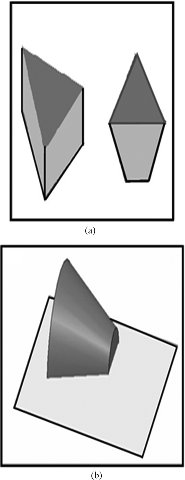
Development of WBDRAs was in full swing by Kishk and his team members at the University of Mississippi. They experimented with various shapes and orientations of probe-fed truncated tetrahedrons [Reference Kishk18]. Maximum broadbanding (40%) was obtained when the narrow base of a tetrahedron was placed on the ground plane (Fig. 7(a)). They also investigated different forms of conical shapes among which the probe-fed split cone gave the maximum bandwidth (50%) [Reference Kishk, Yin and Glisson19] (Fig. 7(b)).
(a) Split cone DRA on ground plane. (b) Truncated tetrahedrons DR blocks. [Reproduced from Kishk et al., Wide-band truncated tetrahedron dielectric resonator antenna excited by a coaxial probe, IEEE Transactions on Antennas and Propagation 51/10 (2003) 2913–2917; Kishk, Yan Yin, and A. W. Glisson, Conical dielectric resonator antennas for wide-band applications, IEEE Transactions on Antennas and Propagation 50/4 (2002) 469–474.]
Stair or step-shaped DRAs were investigated in 2004. Chair et al. designed slot-coupled microstrip line-fed flipped staired pyramid and conical DRAs. The maximum bandwidth obtained was 50% [Reference Chair, Kishk, Lee and Smith20]. In the same year, Pliakostathis and Mirshekar-Syahkal proposed a coaxial probe-fed stepped DRA achieving a 10.1% bandwidth [Reference Pliakostathis and Mirshekar-Syahkal21]. A tile-shaped microstrip-fed DRA of very high permittivity achieved a 25% bandwidth [Reference Bit-Babik, Di Nallo and Faraone22].
In 2007 Chair et al. experimented with stair-shaped DR (see Fig. 7). The structure was fed both by coaxial feed and aperture-coupled microstrip line and a 54.3% bandwidth was obtained [Reference Chair, Kishk and Lee23].
An H-shaped DR had also been studied and the structure was excited by a trapezoidal-shaped patch connected to a microstrip line [Reference Liang and Denidni24]. The impedance bandwidth obtained in this case was 62%.
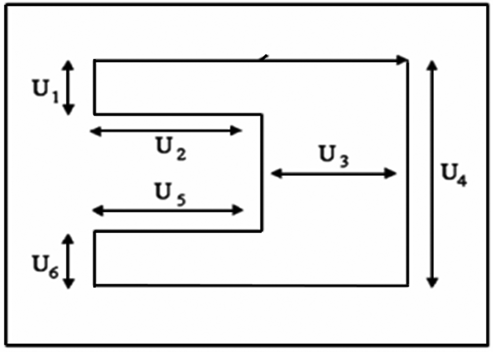
It seems that U-shaped DR drew special attention and several researchers have reported on this particular shape of a DR. Zhang et al. reported elliptical [Reference Zhang, Zhong and Xu25] and triangular patch-fed [Reference Zhang, Zhong and Liang26] U-shaped DR which achieved 74.5 and 84.1% impedance bandwidth. A U-shaped DRA was further reported by Madhuri et al. (Fig. 8) where the antenna was excited by a rectangular ring slot connected to a 50-Ω microstrip line. By properly choosing the parameters of the antenna a wide bandwidth of 58.25% was achieved [Reference Madhuri, Hadalgi and Mallikarjun27].
Top view of U-slot DR showing dimensions of the U-slot. [Reproduced from Madhuri et al., U-slot rectangular dielectric resonator antenna for wideband applications. International Journal of Electronics Engineering, 2/2 (2010) 249–252.]
An overturned L-shaped DRA specially cut from a rod of cylindrical DRA and fed by a conformal strip connected to an SMA connector gave an impedance bandwidth of 66% [Reference Chu, Guha and Antar28].
A very interesting shape of that Bowtie was also investigated by Thamae and Wu in 2010. The shape was obtained by carving out notches from a cylindrical geometry of a DR [Reference Thamae and Wu29]. The antenna when fed by a conventional coaxial probe gave an impedance bandwidth of 49.4%.
In 2012 an asymmetrical T-shaped DRA was excited by an inverted trapezoidal patch. The patch was etched on one side of the DR and connected to an SMA connector through a 50-Ω microstrip line [Reference Gao, Feng and Zhang30]. A pretty good impedance bandwidth of 75.1% was obtained in this case.
Special shaped DRAs like trapezoidal DRA [Reference Danesh, Abdul Rahim and Khalily31] and P-shaped DRA [Reference Khalily, Rahim, Kishk and Danesh32] fed by a microstrip line were also investigated which gave 87.3 and 80% bandwidth, respectively.
DRA with special feed arrangement
Various special feed arrangements had also been used to design WBDRAs. Leung and Leung in 2003 used an innovative excitation method. A cylindrical DRA was excited by a cavity-backed circular aperture fed by a microstrip line with a stub having the shape of a tuning fork. The proposed structure achieved a bandwidth of 38% [Reference Leung and Leung33].
Similar structures were reported again in 2005. A metallic cavity-backed, slot-coupled cylindrical DRA was investigated in the presence of a parasitic rectangular slot in the ground plane. Parametric studies reported a maximum bandwidth of 21% [Reference So and Leung34].
An L-shaped strip-fed rectangular DRA achieved a 17% bandwidth [Reference Menon, Lethakumary, Bijumon, Sebastian and Mohanan35]. In 2009 an L-shaped DRA, excited with a conformal inverted trapezoidal patch feed connected to a microstrip line, achieved a bandwidth of 71.4% [Reference Liang, Denidni and Zhang36].
A new feed of an open half-loop antenna consisting of three strips was investigated by Sulaiman and Khamas in 2011 [Reference Sulaiman and Khamas37]. A rectangular DRA was chosen in this work and a parasitic half-loop was also added to enhance the impedance bandwidth (20%).
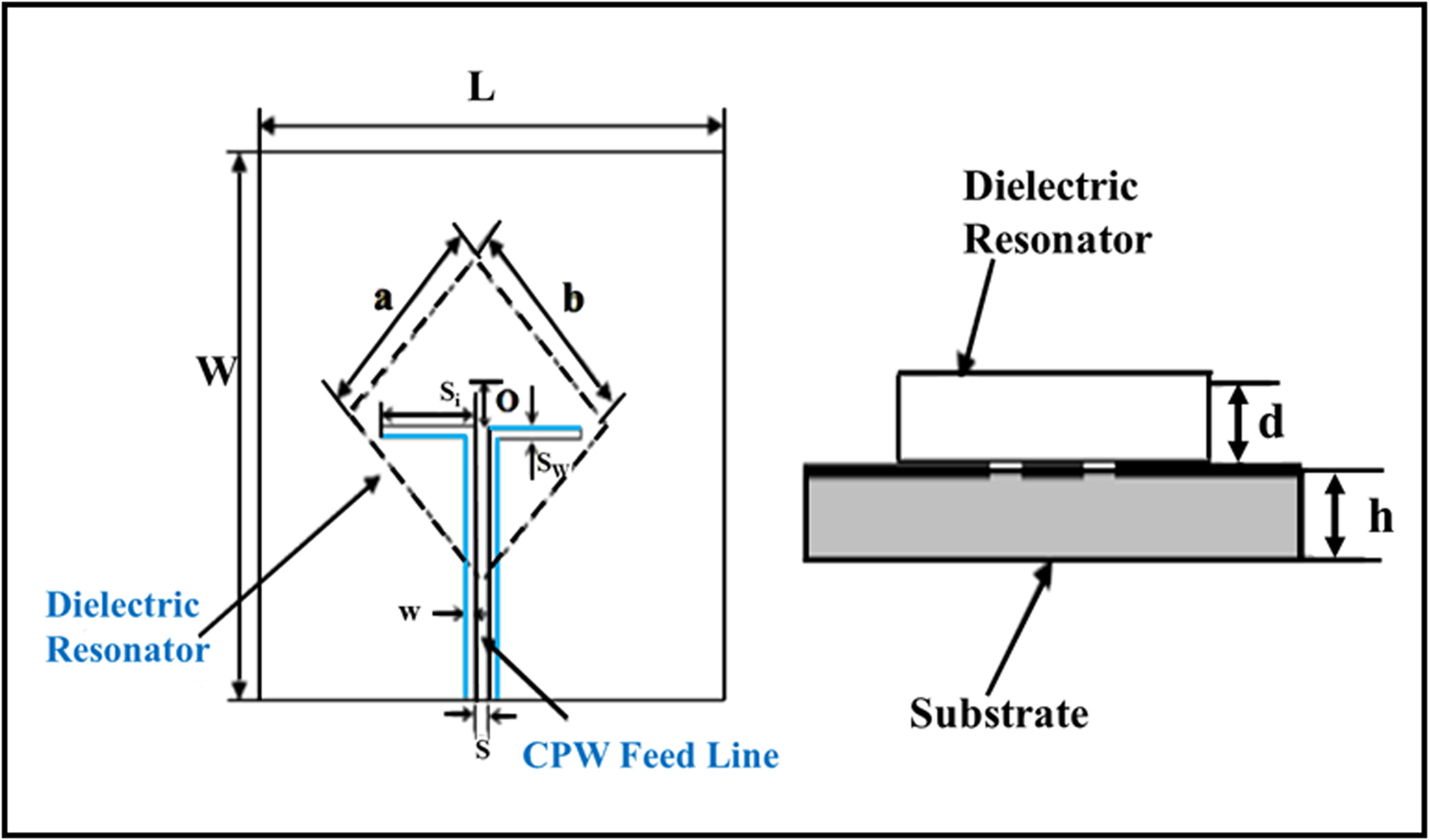
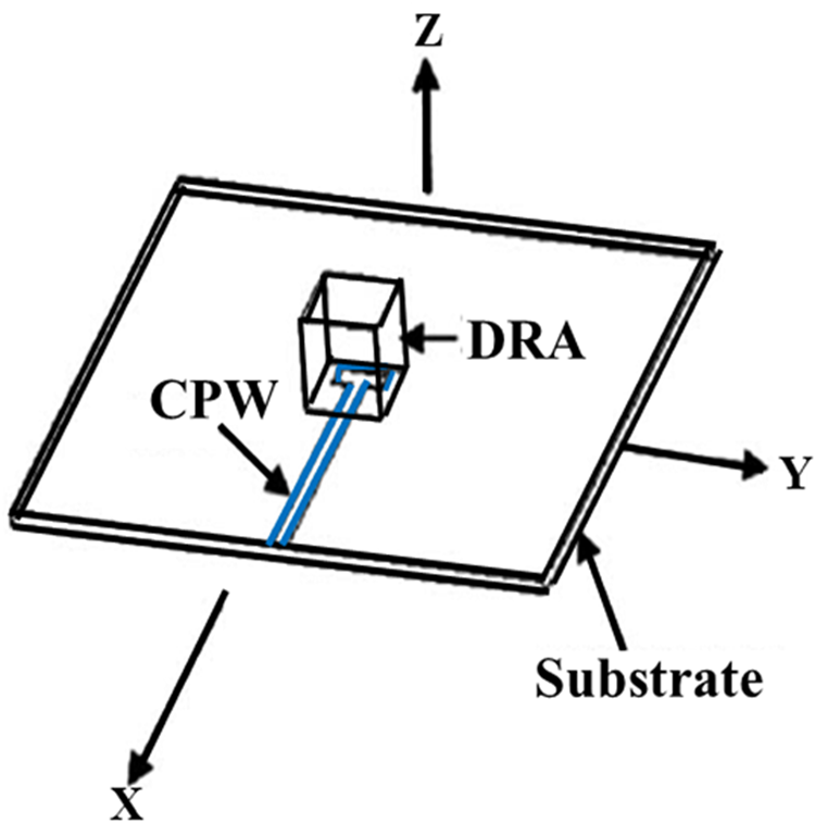
A cylindrical DRA excited by bow-tie cross slots was reported by Patin and Sharma as shown in Fig. 9 [Reference Patin and Sharma38]. For better impedance matching the backside of the substrate had a 50-Ω microstrip line with a small stub at the end. A bandwidth of 17.24% was obtained in this case. A quadrature feed network consisting of a Wilkinson divider and wideband 90° phase shifter, designed with a switched line structure was used to excite the cylindrical DRA to obtain 43.3% bandwidth [Reference Sun and Chen39].
DRA with labels showing important design parameters. [Reproduced from Patin et al., Single feed aperture-coupled wideband dielectric resonator antenna with circular polarization for Ku-band applications, International Journal of Antennas and Propagation, 2012 (2012) 8.]
So, we observe that various techniques have so far been adopted to design wideband antennas in which a single DR block had been used. The most notable impedance bandwidth achieved is 87.3% using a trapezoidal DRA [Reference Danesh, Abdul Rahim and Khalily31] fed by a microstrip line.
DRAs with multi-DRs
The path of bandwidth enhancement technique is long and variant and various research and investigations were also carried out using multiple DR blocks. The subcategories are shown in Fig. 10.
Different techniques adapted for multiple DRs.
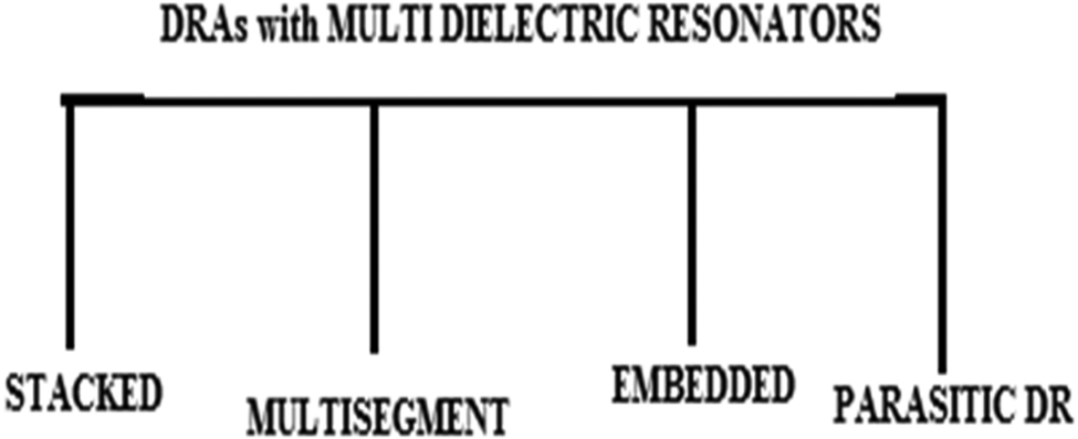
Stacked DRA
The development of WBDRAs was technically started by Kishk et al. involving multiple DRs [Reference Kishk, Ahn and Kajfez40] in 1989 to achieve the broadband although bandwidth enhancement techniques were also reported later using a single DR [Reference Wong, Cheng and Chen2–Reference Sun and Chen39].
Kishk et al., at the University of Mississippi, carried out experiments by placing two cylindrical DRs of different dimensions and permittivity on two layers and excited the structure through a coaxial probe. The resonators were so chosen that they resonate at different frequencies which merge to provide a broad bandwidth of 25%.
The concept of a stacked DRA seemed to be more promising and similar types of investigations were carried out [Reference Kishk, Zhang and Glisson41–Reference Huang and Kishk45] much later also, all of which turned out to be wideband antennas.
In 1995 Shum and Luk experimented with two stacked annular ring DRs excited by the coaxial probe. They also introduced two air gaps in the antenna structure, one between the two DR blocks and another between the lower DR block and the ground plane [Reference Shum and Luk46]. A wideband of 18% was achieved in this case. A similar type of work was carried out again in 1997 [Reference Leung, Luk, Chow and Yung47].
A new type of DRA was proposed to enhance bandwidth in 2005. This structure was made up of 14 layers consisting of alternate dielectric and hexaferrite rectangular slabs with proper values of permittivity and permeability in alternate layers [Reference Buerkle and Sarabandi48]. This special effort was tried out to bring miniaturization into the antenna structure without affecting the bandwidth of the antenna. The structure used two probes for excitation and a 90° hybrid coupler to divide the input power through a microstrip line. An impedance bandwidth of 58% was obtained in this case.
Stacked rectangular DR blocks of different permittivity fed by a 50-Ω coaxial probe with a metallic plate of negligible thickness [Reference Gangwar, Singh and Kumar49], covering the face of the DRA just opposite to the face where the feed was connected was investigated by Gangwar et al. A 50.25% bandwidth was reported in this case.
Furthermore, a triangular-shaped stacked DRA of the same permittivity but different sizes [Reference Kumari, Parmar and Behera50] was excited by a conformal patch connected to a microstrip line, and a 41% bandwidth was obtained.
A four-element three-layered cylindrical DR with a central dielectric cylinder fed by a coaxial probe produced 47% bandwidth [Reference Chaudhary, Srivastava and Biswas51].
Further investigations on stacked DRAs continued and achieved 138% [Reference Ozzaim, Ustuner and Tarim52] and 34.05% [Reference Kakade and Kumbhar53] bandwidth.
Multi-segment DRA
It is well known that the bandwidth of a DRA can be increased by choosing DR material of low permittivity but at the expense of the increased size of the DR block. The problem can be solved by choosing DR material of high permittivity but at the expense of reduced bandwidth. A multi-segment DRA was proposed by many scientists to overcome the difficulty. The technique is similar to that of layered structure to some extent, but here lateral expansion of the area covered by the antenna increases instead of an increase in vertical height.
Moon and Park, in 2000, proposed a novel broadband antenna using this concept. It consisted of two dielectric slabs of low (εr = 9.3) and high (εr = 38) permittivity attached side by side with a thin metallic strip connected to one side of the high permittivity dielectric slab [Reference Moon and Park54]. The structure was placed on a ground plane and excited by a coaxial probe. A 25% bandwidth was achieved in this case.
A multi-segment antenna consisting of four cylindrical DRs [Reference Guha and Antar55], placed around a coaxial probe-fed central dielectric cylinder, was designed by Guha and Antar in 2006. An impedance bandwidth of 29% was achieved in this case.
Development of the wideband antenna was in full swing. Moreover, miniaturization of the antenna was included as one of the additional goals in the process of development of antenna technology. It had already been established that the size of the antenna can be reduced if a metal plate is placed on one side of the DRA [Reference Tam and Murch56–Reference O'Keefe, Kingsley and Saario59]. This concept was used by Rezaei et al. to design a WBDRA. They used a two-segment rectangular DRA separated by a metal plate. When the structure was excited by an open-ended 50-Ω microstrip line the antenna achieved a pretty good bandwidth of 76.8% for a suitable aspect ratio and optimum position of the feed line [Reference Rezaei, Hakkak and Forooraghi60]. A similar type of work was again carried out in 2008 with different dielectric materials fed by a microstrip line which again turned out to be a wideband antenna [Reference Ain, Hassan, Othman, Sreekantan, Hutagalung and Ahmad61]. A wideband of 40% bandwidth was achieved in 2013 by placing dielectric parallelepipeds around a coaxial probe which gave the antenna a bird's nest shape [Reference Pan and Leung62].
Embedded DRA
Another technique that was explored to enhance the bandwidth of DRAs was the embedded structure of DRs. In 1997 Sangiovanni et al. reported on embedded DRAs where two DR blocks of the cylindrical shape of different permittivity and same height were placed one within another [Reference Sangiovanni, Dauvignac and Pichot63]. An air gap was also created between the ground plane and the dielectric blocks and the structure was excited by a coaxial probe that was connected to both the cylinders. For a low-profile antenna structure (a/h = 6) 30% impedance bandwidth was reported in this work. A similar type of investigation was again carried out in 2002 where the realization of omnidirectional radiation pattern was set as an additional goal along with bandwidth enhancement. Numerical analysis was carried out using the method of moments and verified by the finite-difference-time-domain (FDTD) method. A bandwidth of 47% was achieved in this work [Reference Ong, Kishk and Glisson64].
Parametric study of a slot-fed rectangular embedded DRA [Reference Kishk65] achieved a 50% bandwidth in 2005.
A new type of structure where along with embedded, stacked geometry was also used, as reported by Ruan et al. [Reference Ruan, Guo and Shi66]. Here at the bottom a cylindrical DR was embedded within a large annular ring DR and above it, another cylindrical DR was placed to be excited by the coaxial probe. Moreover, an air gap was also created between the bottom DR and the ground plane to escalate the bandwidth to as high as 67%.
Multiple studies on stacked, core plugged embedded (the inner plug is almost 30% of the total volume of the DRA), and embedded stacked geometry were again reported in 2006 by Walsh et al. [Reference Walsh, De Young and Long67]. An impedance bandwidth of up to 68.1% was achieved in this case.
Work on embedded geometry was continued and Chair et al. in 2007 again reported on a WBDRA (28% impedance bandwidth) where an eye-shaped DRA was placed within an elliptical-shaped DRA and fed by a slot in the ground plane connected to a microstrip line [Reference Chair, Kishk and Lee68].
DRA with parasitic DR
As a DR is a high Q cavity, it provides narrow bandwidth when used as a radiating antenna. So, researchers were questing for new techniques to reduce its Q factor to enhance the bandwidth of DRAs. Although the real estate required is more compared to the previously discussed techniques parasitic dielectric blocks were used along with the driving DR to substantially enhance the bandwidth of the antenna. The method was first introduced by Simons and Lee in 1993 [Reference Simons and Lee69]. Here they placed two cylindrical parasitic DRs one on two sides of the driving cylindrical DRA which was excited electromagnetically with a grounded CPW through an aperture in the common ground plane. Good enhancement in bandwidth was obtained in this method also. A similar technique was adopted by Petosa et al. in 1998 where a slot-fed rectangular DRA was used with two parasitic DR blocks [Reference Petosa, Ittipibon, Mantar, Roscoe and Cuhaci70]. The three DR elements were tuned in such a way so that they gave an impedance bandwidth of 17%.
After analyzing all the different techniques, the most significant result in terms of impedance bandwidth is observed in the case of a stacked conical ring DRA which is 138% [Reference Ozzaim, Ustuner and Tarim52].
Hybrid DRA
Another technique was also used to enhance the bandwidth of a DRA. Two different radiating structures were coupled together so that the resonant bandwidths merged to enhance the total bandwidth of the antenna structure. Hence the antenna becomes a hybrid. A WBDRA (impedance bandwidth: 12.3%) was designed by placing a DR at the appropriate position on a patch where both the patch and the DR were resonating structures [Reference Gupta, Sinha, Koul and Bhat71]. A slot-coupled rectangular DR fed by a microstrip line was reported in 2010 [Reference Hadalgi, Madhuri and Mallikarjun72]. Here also both the slot and the DR were resonating structures and the two resonances merged to give a wide bandwidth of 42.1%. A new type of hybrid antenna was proposed by Estelle in 2001. It was referred to as a dielectric resonator on patch. Here the DRA was excited through an upper and lower slot placed above and below the resonating patch on which the dielectric block was placed to couple the electromagnetic energy in an effective way [Reference Esselle73]. A 21% bandwidth was obtained in this work. Later on, in 2005 Esselle and Bird again reported experimental results on the same DRA in which the bandwidth obtained was 23.5% [Reference Esselle and Bird74]. Buerkle et al. reported a technique in which they combined a slot antenna and a DRA to obtain a bandwidth of around 25% [Reference Buerkle, Sarabandi and Mosallaei75]. Hybrid antennas were again reported the very next year. Gao et al. designed a CPW inductive slot-fed RDRA where the two resonances from the two radiators again merged to achieve a 28.9% bandwidth [Reference Gao, Ooi, Ewe and Popov76]. A similar technique was again used by Gao et al. in the same year to achieve a 23.5% bandwidth. But compared to previous works here a back cavity was formed underneath the slot to suppress the backward radiation [Reference Gao, Popov, Ooi and Leong77].
Here the hybrid structure of slot and DR achieved the notable bandwidth of 42.1% [Reference Hadalgi, Madhuri and Mallikarjun72] which was much less than the maximum impedance bandwidth that had been achieved in earlier two cases (DRAs with single DR, DRAs with multi-DRs).
Broad classification of multiband antennas
Several works had been carried out to design multi-frequency antennas also and major categorization is done depending on whether the antennas are
• Dual-band
• Triple-band or multi-band in nature.
Dual-band DRA
The major sub-categories for dual-band DRAs are shown in Fig. 11 and are discussed in detail in the subsequent section.
Different techniques adapted for dual-band DRA.
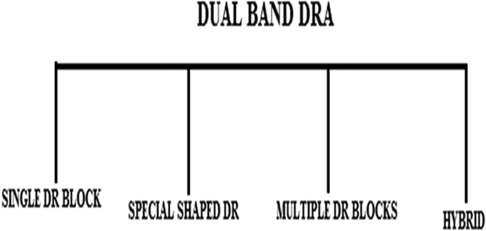
Dual-band DRA with single DR block
In 2003, a dual-band DRA was designed by exciting a cylindrical DR by a pair of concentric C-shaped slots. The structure was fed by a microstrip line placed on a ground plane [Reference Lin and Huang78]. In the next year, Sung et al. proposed a dual-band ring-shaped DRA excited by a simple microstrip feed line [Reference Sung, Ahn and Kim79].
In 2004 Denidni et al. designed a dual-frequency antenna where multi-eccentric rings are used as feeding structures to a hemispheric DRA. Here the inner eccentric ring slot is driven directly by a coaxial cable which in turn electromagnetically couples other ring slots [Reference Denidni, Rao and Sebak80]. These coupled multi-eccentric ring slots finally fed the DRA. Two resonant frequencies were observed at 2.46 and 3.64 GHz. The same technique had been used for a cone-shaped DRA. Again, dual resonances were observed at 2.55 and 3.90 GHz. A similar type of dual-band DRA was designed by Denidni et al. where hemispherical DR was excited by two ring slots [Reference Denidni, Rao and Sebak81]. Two different modes of DR were excited to achieve dual-band operation.
In 2005 a dual-frequency DRA was designed by Li and Sun using an inverse T-shaped parasitic strip [Reference Li and Sun82]. Here a cylindrical DR was fed by a microstrip line. Moreover, an asymmetrical T-shaped parasitic strip was mounted on the DR. Dual resonant frequencies were observed for various lengths of the parasitic strip.
A dual-band antenna with two different radiation patterns was designed in 2009 with a cylindrical DRA [Reference Hady, Kishk and Kajfez83] and the structure was excited simultaneously by a printed microstrip feeding network and a coaxial probe. Experimental verification was carried out and the antenna was found suitable for GPS and WLAN applications.
A slot-coupled microstrip-fed dual-band rectangular-shaped DRA was designed by Fang and Leung in 2011 [Reference Fang and Leung84]. Higher-order modes along with the fundamental mode were generated and the antenna was found suitable for WiMAX and WLAN applications.
Dual-band DRA with special shaped DR block
Just like the case of wideband antennas, different types of shapes had also been investigated to date to achieve dual-band operation. For instance, in 2004 an eye-shaped DRA was proposed by Paul et al. [Reference Paul, Mridula, Mohanan, Bijumon and Sebastian85]. The antenna could be placed in two orthogonal positions on the microstrip feed line and many resonant modes were excited among which two turned out to be very prominent ones.
A dual-band antenna was proposed by Chang and Kiang with a new structure of the DR block [Reference Chang and Kiang86] as shown in Fig. 12. A rectilinear DR block was split and notches were carved out from specific portions of the resonator to obtain a reduced Q and hence an increased bandwidth. The resonating structure was excited by an aperture-coupled microstrip line. Two bands were obtained ranging from 3.375 to 3.93 GHz and 5.08 to 5.415 GHz.
Configuration of split DRA: panoramic view. [Reproduced from Chang et al. Dual-band split dielectric resonator antenna, IEEE Transactions on Antennas and Propagation, 55/11 (2007) 3155–3162.]
A 15% bandwidth was achieved in the first resonant band, but only a 6% bandwidth was obtained in the second one. Shapes, like half-cylindrical DRA [Reference Parmar, Kumara and Behera87] and Z-shaped stepped DRA [Reference Chatila, Bandyopadhyay and Maji88] were also investigated and both of them were suitable for dual-frequency operations.
Dual-band DRA using multiple DR blocks
Reports on multi-resonant antennas date back to 1997 [Reference Fan and Antar89]. In 1997, Fan and Antar used two rectangular DR blocks to achieve dual-band operation. Both the resonators were placed near the two edges of a single aperture-coupled microstrip line and the dimensions of the DRs were so chosen that their resonant frequencies are quite apart from each other. Dual frequency was also obtained using cylindrical DRs of different permittivity, placed one within the other, and excited by the coaxial probe in 2003 [Reference Nannini, Ribero, Dauvignac and Pichot90] as shown in Fig. 13. A similar dual-band embedded structure was experimented during 2011 [Reference Benomar, Hacene, Megnafi and Vaudon91].
3-D view DRA configuration. [Reproduced from Benomar et al., embedded dual-band cylindrical dielectric resonator antenna. International Journal of Communications, Network and System Sciences, 4 (2011) 656–661.]
Dual-band hybrid DRA
Just like WBDRAs, different types of hybrid structures had also been investigated to achieve dual-band DRAs. The basic concept of combining a resonator with a feed arrangement which again itself is a radiator continued to be the same driving logic in the design of the hybrid structures.
In 2004, Denidni and Rao proposed a dual-frequency hybrid rectangular and cylindrical DRA where the feed consisted of a circular slot along with an eccentric ring slot placed on the co-plane ground [Reference Denidni and Rao92] (Fig. 14). The idea was to excite two resonant frequencies, one from the DRA and the other from the resonating feed structure. A hybrid dual-band DRA was suggested by Rao et al. next year where a T-shaped microstrip line acted as a resonator as well as a feed structure to a circular disk DR [Reference Rao, Denidni, Sebak and Johnston93]. Rao et al. designed another hybrid DRA in the same year. The proposed DRA consisted of a disk DR coupled to a rectangular slot fed by a microstrip line [Reference Rao, Denidni and Sebak94]. Moreover, a circular metal sheet partially covered the top of the DR to substantially reduce the size of the antenna compared to a conventional hybrid slot-coupled DR. The journey continued and another hybrid dual-band DRA was designed with a thin circular disk DR excited by a microstrip-fed dog-bone slot [Reference Denidni and Rao95]. Another hybrid DRA was proposed where along with dual-band operation two separate beam patterns were obtained [Reference Rao, Denidni, Sebak and Johnston96]. The antenna consisted of a circular disk DR and a T-shaped microstrip line and produced independently broadside and conical radiation patterns in the first and the second resonant bands.
Proposed antenna: (a) front view and (b) geometry. [Reproduced from Mahender et al., Compact dual-band hemispherical dielectric resonator antenna. International Conference on Electronic Systems (ICES-2011), NIT Rourkela, India, January 7–9 (2011) 252–254.]
A novel hybrid DRA was designed with a CPW inductive feeding slot with a rectangular DR placed on it [Reference Gao, Ooi and Popov97] in 2006. More designs of dual-band DRAs were suggested later on using DRs of various shapes and CPW inductive slots [Reference Lin, Chen and Lin98, Reference Mahender, Kumari and Behera99].
In 2011 Batra et al. proposed a layered structure for a dual-band DRA. The structure is a combination of a slot antenna and a DRA. Here a rectangular-shaped dielectric slab is placed on an inductive slot cut on a ground plane. Below the ground plane, another slab of dielectric having higher permittivity than that of the dielectric slab had been placed with a microstrip feed line below it [Reference Batra, Sharma and Kohli100]. The antenna with its stable gain can be used for C and X band applications.
Two novel types of DRAs were also reported in 2013 which can be used either in wideband mode or dual-band mode [Reference Khalily, Rahim, Murad, Samsuri and Kishk101, Reference Sun and Leung102].
Triple band and multiband DRAs
Reports on triple or multiband DRAs are few and limited. Hence the authors are more interested to present a review on year by year basis.
Multiple elements were used to realize triple resonance in 1998. Here a stack of DR elements was placed on a ground plane and was coaxially fed. The stack started with an annular ring on which two rectangular blocks of DR having the same height and same dielectric constant were placed one above the other. A simulated air gap had also been introduced between the stack and the ground plane with the help of foam placed in between the two. Triple resonances with variable 10 dB bandwidth were achieved with the proposed antenna structure [Reference Sangiovanni, Dauvignac and Pichot103].
Hamsakutty et al. proposed a very simple triple resonant antenna. It consisted of a cylindrical DR with a metal coating at the top which had a circular slot in the middle of the DR block [Reference Hamsakutty, Kumar, Bindu, Thomas, Lonappan, Yohannan and Mathew104]. The antenna was excited by a coaxial probe to obtain triple resonance.
The hexagonal shape of DR was studied and reported by Hamsakutty et al. in 2006 [Reference Hamsakutty, Praveen Kumar, Yohannan and Mathew105]. A coaxial cable was used to excite the specially shaped DR and three resonant frequencies were observed at 1.92, 2.57, and 3.25 GHz.
Two rectangular DR blocks excited by a printed stub on an FR4 substrate, which acted as a printed monopole, were used in 2011 to obtain triple resonance [Reference Huitema, Koubeissi, Mouhamadou, Arnaud, Decroze and Monediere106].
A novel small triple-band rectangular DRA was designed using three-segment thin dielectrics having different sizes, which produce an omnidirectional radiation pattern [Reference Bemani, Nikmehr and Younesiraad107].
A triple-band triangular-shaped DRA array was proposed in 2012. The antenna consists of two triangular-shaped DRA, which were excited by a conformal patch connected to a microstrip line [Reference Kumari and Behera108].
Four resonant frequencies were reported by Hamsakutty et al. in 2006. A hexagonal DRA was excited by a single coaxial probe and four resonant bands were observed in this case [Reference Hamsakutty, Kumar, Yohannan, Bindu and Mathew109]. A hybrid multi-frequency antenna was designed by using a cubic DRA and CPW loop radiator which also acted as a feed to the DRA. Six different resonant frequencies were achieved between 2 and 7 GHz with this compact design with the highest gain (8 dB) being achieved at 4.69 GHz [Reference Bhattacharya (Mitra) and Gupta110] (Fig. 15).
Structure of the proposed antenna. [Reproduced from Bhattacharya (Mitra) et al., A novel multifrequency hybrid antenna. Microwave and Optical Technology Letters, 55/11 (2013) 2712–2715.]
Another quadra-band antenna consisting of three segments of thin dielectric of different sizes and separated by metal plates, fed by a microstrip line, has been reported in 2014 [Reference Younesiraad, Bemani and Nikmehr111].
So, we observe that stacked multiple elements of DR blocks, special shapes like cylindrical DRs with circular slots, hexagonal or triangular-shaped DRs as well as hybrid structures (CPW-fed RDRA) are some of the techniques that had been used to design triple-band and multiband DRAs. The most notable is the one where six different resonant frequencies were obtained with a very simple hybrid structure [Reference Bhattacharya (Mitra) and Gupta110].
Wide dual-band DRA
Having understood the immense necessity of both wideband and multiband antennas researchers moved one step forward to design antennas that are both multiband and wideband. Few works have so far been carried out in this field.
In 2003, Lan et al. proposed a multi-element wide dual-band antenna [Reference Lan, Chaudhuri and Safavi-Naeini112]. It consisted of a rectangular DR, foam former, and a grounded conductor plate. The conductor plate was slotted by L-shape to realize a parasitic inverted-L plate. Moreover, a T-junction was printed on the top of the DR which was connected to a microstrip line through a vertical strip attached to one side of the DR. Electromagnetic coupling took place between the inverted-L plate and the DR. The DR served as a dual role here as a radiator and the feed element to the inverted-L plate. The later one in addition to reducing the DR size acted as an additional radiating element. The dual-band obtained with this antenna ranged from 2.4 to 2.5 and 5 to 6 GHz among which only one band is wide.
In 2006, Rezaei et al. designed a dual WBDRA with a rectangular DR block excited by a microstrip line which had an additional L-shaped feed line [Reference Rezaei, Hakkak and Forooraghi113]. Two different modes having separate resonant frequencies were excited ranging from 5.03 to 5.62 and 6.22 to 7.96 GHz. The first band achieved an 11% bandwidth whereas the second one achieved 24.5%. In the same year, Lim and Leung proposed a dual wideband antenna in which a rectangular DR was excited by an aperture-coupled microstrip line [Reference Lim and Leung114]. An impedance bandwidth of 28% (2.21–2.855 GHz) and 11.9% (4.835–5.455) were obtained in this case.
Latest trends in DRA
DRAs became quite a popular and interesting topic in 2015 and consistent research work is being continued to date to obtain wide banding, high gain, and various other objectives. In 2015, three blocks of dielectric material, each with a different dielectric constant provided a Voltage-Standing-Wave-Ratio (VSWR) bandwidth of 86%. An air gap was introduced in the middle section to obtain this enhanced bandwidth and a peak gain of 5–7 dBi was also achieved with this design [Reference Iqbal and Esselle115]. Generation of higher-order modes and merging of modes technique was adopted to achieve a bandwidth of 8.2 GHz with a gain of 9 dBi using the dual excitation method for RDRA in the same year [Reference Gupta and Yaduvanshi116]. A 124.4% impedance bandwidth was reported in a work where a cylindrical DRA was fed by a rounded bevel-shaped patch. The CPW technique along with a truncated ground plane was also included to achieve the desired result [Reference Prachi and Chaudhary117].
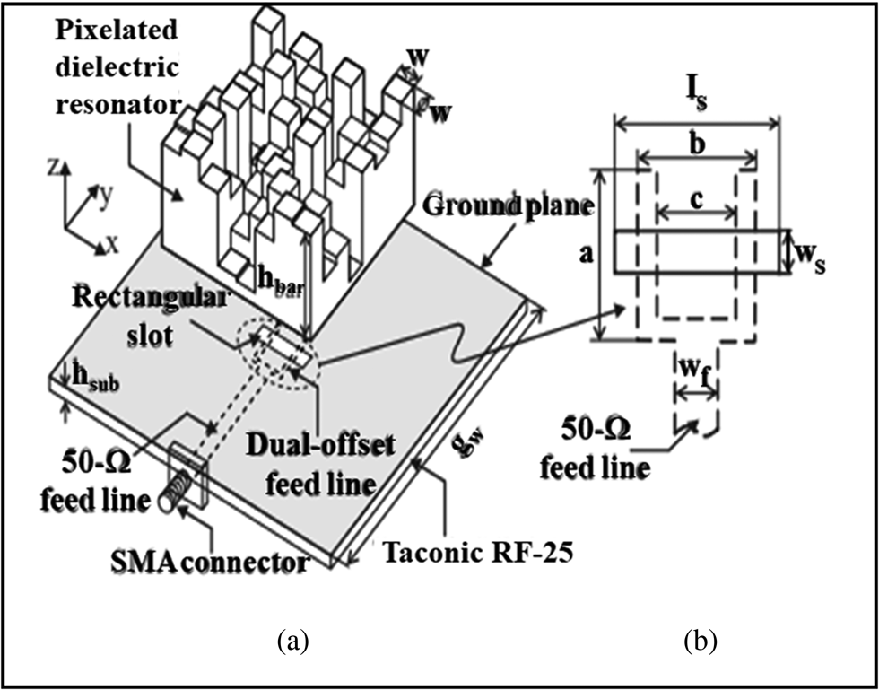
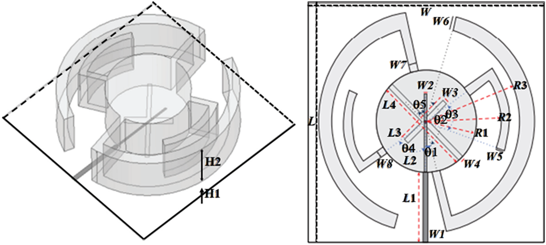
A comprehensive parametric study led to the design of a compact DRA with band-notched characteristics with a −10 dB impedance bandwidth of 23% from 9.97 to 12.558 GHz, and a maximum gain of 7.23 dBi [Reference Majeed, Abdullah, Sayidmarie, Abd-Alhameed, Elmegri and Noras118]. A monopolar-spiral slot fed by a microstrip line consisting of a strip and a half ring was used to obtain a global bandwidth of 30.7% in the case of an RDRA in 2016 [Reference Li, Li and Wang119]. Special geometry like a pixelated DR consisting of 8 × 8 grid DR bars with different heights fed by a narrow rectangular slot was investigated using the genetic algorithm in the same year. The measured 10 dB reflection bandwidth obtained was 32.32% with a peak gain of 6.13 dBi at 3.2 GHz [Reference Trinh-Van, Yang, Lee and Hwang120] (see Fig. 16).
Geometry of the proposed antenna: (a) exploded 3-D view and (b) feeding configuration. [Reproduced from Son et al., A wideband circularly polarized pixelated dielectric resonator antenna, Sensors 16/9 (2016) 1349.]
A Z-shaped hybrid DRA fed by a conformal strip achieved an impedance bandwidth of about 114.5% when two different materials were used to design the antenna (Fig. 17). An average gain of 6 dBi was reported in this work [Reference Trivedi and Pujara121]. The presence of two printed patches with two air layers between the patches and the DR block led to the design of an antenna with a return loss bandwidth of 25.6%.
Proposed antenna configuration. [Reproduced from Ali et al., Stacked conical-cylindrical hybrid dielectric resonator antenna for improved ultrawide bandwidth, Progress in Electromagnetics Research Letters, 79 (2018) 79–86.]
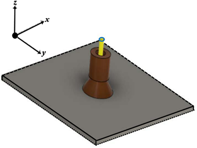
Low cross-polarization levels both in the E and H planes along with gains of 6.3 and 8.2 dBi were reported in this work [Reference Dong, Xu, Lin and Zhang122]. Placing symmetrically tapered sheets on both sides of the feed line, a cylindrical DRA was designed. Circular polarization was triggered and a bandwidth of 16.77% with a peak gain of 5.92 dBi was achieved [Reference Dash and Khan123]. A 59.7% impedance bandwidth was reported in a work where merging of modes was again used for an A-shaped DRA fed by a conformal strip. The reported gain ranges from 5.29 to 7 dBi within the operating range [Reference Sharma, Sarkar and Biswas124]. A coaxial probe-fed dual-segment half-cylindrical DRA was designed to achieve a bandwidth of nearly 98% with a constant gain of 4.8 dBi throughout the operational bandwidth [Reference Ranjan, Gangwar, Singh and Varshney125]. A stacked conical–cylindrical DRA excited by a simple coaxial monopole achieved a ultra-wideband response with an impedance bandwidth of 148.6% and 7.14 dBi peak gain [Reference Al-Azza, Malalla, Harackiewicz and Han126] (Fig. 17). In 2019, an H-shaped DRA was designed which provided an impedance bandwidth of 24%.
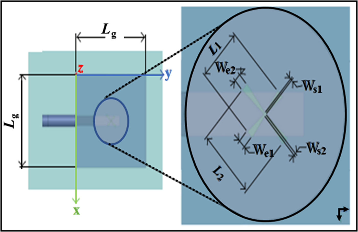
The antenna was probe-fed and achieved a gain of around 6 dB [Reference Gaonkar and Patel127]. A multi-layered RDRA was designed in the same year which was probe-fed and achieved a bandwidth of 90.9% [Reference Wang, Zhang, Sun and Xiao128]. To improve the performance of the antenna partial ground plane multi-stacked technique was adopted along with an air gap between the two DR elements to design a T-shaped DRA. Impedance bandwidth achieved was 84% and the maximum gain achieved was 4.72 and 4.3 dBi at 5.77 and 9.76 GHz, respectively, for this probe-fed antenna [Reference Chauhan and Mukherjee129]. A unique technique of using a copper metal wall along with a narrow RDRA was used in a design in 2019 to achieve broadband (10.95–18.30 GHz) and directive high gain. The antenna was probe-fed and an air gap was also introduced between the antenna and ground plane [Reference Roy and Basu130]. A wideband differential hollow RDRA with an air gap displaced from the center was used to merge higher-order modes which achieved nearly 44 and 46% impedance bandwidth for the single and dual port, respectively. A lower cross-polarized field with a stable broadside radiation pattern was an additional achievement in this design [Reference Fang, Shi and Sun131]. An “OM”-shaped DRA fed by a microstrip feed line along with a p-type transformer was reported in 2020 which achieved a measured impedance bandwidth of 5.25 GHz from 3.8 to 9.05 GHz and 1.5 GHz from 10 to 11.5 GHz and a peak measured gain of 7.68 dB at 10.5 GHz (with an average gain of 4.6 dB) [Reference Yadav and Kaur132]. An S-shaped probe-fed DR with a metalized edge and two rectangular dielectric resonator (RDRs) blocks achieved an impedance bandwidth of approximately 66.8% and a peak gain of about 4.64 dB. The two added RDRs enhance the radiation characteristics and compensate for the beam squint errors [Reference Abedian, Khalily, Singh, Xiao, Tafazolli and Kishk133]. A circularly polarized (CP) DRA loaded with strips has been designed in 2021 where an orthogonal cross-slot along with a stepped microstrip-line is used to couple the electromagnetic energy. The measured impedance bandwidth obtained is 54% [Reference Hao, Wang, Li and Yin134] (Fig. 18).
Structure of the presented CP DRA. [Reproduced from Hao et al., A new wideband circularly polarized dielectric resonator antenna loaded with strips, International Journal of Antennas and Propagation 2021 (2021) 9966495.]
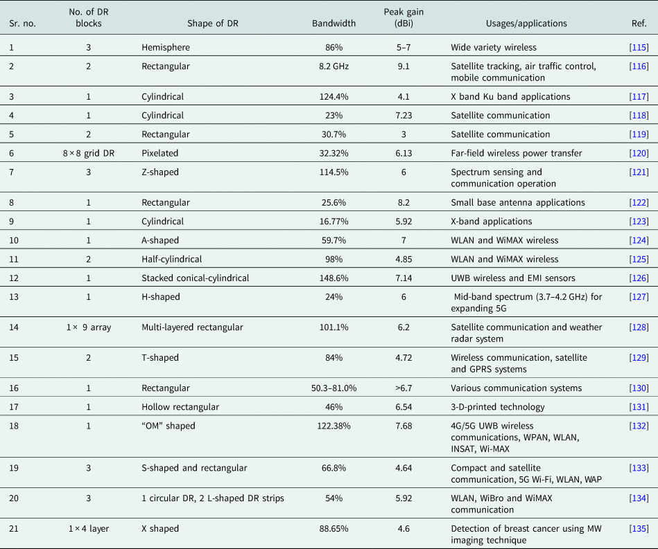
A comparison of the latest trends of DRAs is presented in Table 1 based on the different parameters-based antennas.
Different parameters-based antennas and their applications
Discussion on the challenges of the DRA from design to fabrication
Since the results of the DRA depends on many factors several challenges are to be met. First of all, the dielectric constant of the material should be accurate and homogeneity has to be maintained throughout the DR block. Hence the material has to be procured through some professional manufacturers. This may lead to an unforeseen waiting time before the experimental work can be started. Moreover, the shape and size of the antennas should exactly match the theoretical design to get an accurate result which requires the usage of CNC machines and additional care.
High precision has also to be maintained while connecting the feed system to the antenna so that no unnecessary leakage of energy takes place. Feed systems like CPW are also to be fabricated professionally, which is time-consuming by nature. Mounting the DR block on the substrate is another vital challenge as it has to be done without disturbing the dielectric constant of the DR block. The task becomes more difficult if optimization has been done concerning the position of the DR block and the feed structure to achieve the desired result. Last but not least, a proper anechoic chamber is necessary to get the correct results.
Conclusion
In the last two decades, two classes of novel antennas have been investigated and extensively reported on: microstrip patch antennas and DRAs. Both are highly suitable for the development of modern wireless communications. But DRAs have some advantages like low loss, low cost, lightweight, small size, high radiation efficiency, etc. compared to microstrip antennas. All these features have made DRAs more suitable for wireless applications. Enhancement of impedance bandwidth with high radiation efficiency had been the primary goal from the very beginning of antenna designing. To achieve these primary goals researchers have reported various techniques and various shapes of DRs. A single antenna then can be used for various applications and a communication system then can be compact and reduced in size. For the same reasons, multi-frequency antennas have also become popular in wireless communication systems.
Cutting-edge technology and state-of-the-art design have enriched the world of microwave antennas to a significant level. Considering the importance and numerous applications of both wideband and multi-frequency antennas, the authors were motivated to present a review on DRAs covering the content from a substantial number of published articles from different research groups, and thus covers quite a broad spectrum of the work so far done on DRAs. Similar types of work in the initial years are clubbed together. Hence anyone new to this field will get an exhaustive idea about how the field of DRAs has evolved over years. The latest trend is also noticeable as the work of the last few years is presented in a nutshell. It will not only help to conceive new ideas, but also perform a quick comparative study of the results.
Future scope
The plethora of designs in the case of wideband or multiband DRAs is fascinating but the number is quite limited in the case of dual WBDRAs. New types of hybrid structures coupled with special shapes can be investigated to obtain better performance characteristics. Research can be carried out by using the Goubau line as the feed structure and various characteristics of the antenna can be thoroughly studied. Very special shapes which may look like a lamp-shade or a vase may be designed which will provide multi-frequency and broadband characteristics. These can be used for indoor applications enhancing the acsthetic look of the place and will be easy to camouflage at the same time. Designs should also be done keeping in mind some special applications. New designs can be made so that DRAs become useful in UWB-IoT applications in the 5G range. DRAs can also be designed for applications like near-field probing in EMI-EMC receivers.
Acknowledgements
The authors acknowledge the support and encouragement of their families in writing the paper.
Conflict of interest
The authors declare no competing financial interests and have no conflict of interest.
Disclosure statement
We the author(s), hereby declared that the work presented in this work has not been published nor submitted elsewhere for publication. No conflict of interest was reported by the author(s).
 Dr. Sriparna Bhattacharya (Mitra) has done her B.Tech and M.Tech from the Department of Radio Physics and Electronics, Calcutta University in 1999 and 2005, respectively. She received her Ph.D. from the University of Jadavpur in 2016. Her research area is in broadbanding and multi-frequency in dielectric resonator antennas. Presently, she is very much interested to work on condensed matter materials physics as collaborative work with Prof. SC Ray, Department of Physics, University of South Africa. At present, she is associated with the Department of Electronics and Communication Engineering as an assistant professor at the Heritage Institute of Technology, Kolkata, India. She has a long teaching and research experience and has published a substantial number of articles in different international journals.
 Prof. Sekhar Chandra Ray (Ph.D. University of the North Bengal, India) is the top 2% scientists in the world compiled by Stanford University in 2020 and 2021 (PLoS Biology, October 2020). He is currently a professor of physics at the University of South Africa in experimental condensed matter physics. Prof. Ray hails from India where he completed his doctoral studies which focused mainly on photovoltaic solar-grade materials. He has worked as a research fellow and visiting scientist in Italy (INFM Fellow), Taiwan (NSC Fellow), Spain (ICMM, CSIC, Foreign Researcher Fellow, Ministry of Science and Technology, Spain), South Korea (Brain Pool Research Fellow, Govt. South Korea), and India (IACS, Visiting Scientist). Prof. Ray's research group focuses on carbon nanostructures and their composite materials in electronic structure/magnetic properties for the possible fabrication of spintronic device applications and bioimaging processes. Prof. Ray has also worked on different diluted magnetic semiconductor oxide materials. Prof. Ray is expertise in “synchrotron radiation-based spectroscopy and microscopy” and he is working on it for more than last 20 years. Based on his expertise, Prof. Ray received an 11M rand (≈USD 1.0M) NNEP fund from NRF (South Africa) to establish XPS-UPS dual-type spectrometer machine in the Department of Physics, University of South Africa. Prof. Ray is working with a large number of research groups worldwide. At present, Prof. Ray is working on different 2D-structure materials that include not only graphene-based materials but also stanene, germanene, MoS2, silicene, etc. During his last 25 year research career, he has published more than 175 peer-reviewed research articles, including eight in Nature Publishing Group (NPG) journals with more than 5600 citations in an internationally recognized journal. Prof. Ray has peer-reviewed more than 500 articles for different international journals and he is also an editorial board member of Scientific Reports, NPG journal.


 Open access