


1. Introduction
Bluff body flows at low Reynolds numbers result in a steady laminar regime. With the increase of the Reynolds number past its critical value  $Re_c$, a supercritical Hopf bifurcation gives rise to periodic vortex shedding for canonical geometries such as circular (
 $Re_c=47$) or square (
 $Re_c=46$) cylinders (Provansal, Mathis & Boyer Reference Provansal, Mathis and Boyer1987; Jiang & Cheng Reference Jiang and Cheng2018). The vortex shedding mechanism persists at turbulent regimes as it has been demonstrated experimentally for spanwise-symmetric bodies (cylinders) (Tudball-Smith et al. Reference Tudball-Smith, Leontini, Sheridan and Jacono2012), three-dimensional axisymmetric wakes (Rigas et al. Reference Rigas, Oxlade, Morgans and Morrison2014) and square-back bodies (Grandemange, Gohlke & Cadot Reference Grandemange, Gohlke and Cadot2013). Vortex shedding plays a key role in engineering applications as it can cause a considerable increase in the mean drag and lift fluctuations, structural vibrations, resonance and even acoustic noise. Hence, numerous attempts have been made to control and/or suppress it via passive and active techniques (Choi, Jeon & Kim Reference Choi, Jeon and Kim2008).
Among the various active control methods which have achieved drag reduction are bluff body streamwise or transverse oscillations (Carberry, Sheridan & Rockwell Reference Carberry, Sheridan and Rockwell2003, Reference Carberry, Sheridan and Rockwell2005) and rotational oscillations of the cylinder (Poncet Reference Poncet2002). In the numerical study of Kim & Choi (Reference Kim and Choi2005), spanwise blowing/suction was applied over a circular cylinder to reduce the drag. It was found that in-phase forcing (between the upper and lower blowing/suction profiles) resulted in significant drag reduction for a wide range of Reynolds numbers whereas out-of-phase forcing achieved drag reduction only for high Reynolds numbers. Further, the mechanism responsible for the drag reduction by the in-phase forcing was reported to be the attenuation of the vortex shedding caused by a phase mismatch along the spanwise direction. Contrarily, the drag reduction by the out-of-phase forcing was attributed to the spatial delay of the vortex shedding and the distortion of the separating shear layer.
Wood (Reference Wood1964) and Bearman (Reference Bearman1967) experimentally achieved drag reduction by active base bleed from the trailing edge of the bluff body which resulted in the weakening of the vortex shedding. However, Howell, Sheppard & Blakemore (Reference Howell, Sheppard and Blakemore2003) noted that the positive effects of the base bleed can be negated by the power required to generate the bleed flow for the flow over a bluff body with a car-like shape. Littlewood & Passmore (Reference Littlewood and Passmore2012) reduced (experimentally) the drag of a simplified  $1/4$ scale square-back vehicle by applying steady blowing at various angles on the roof of the trailing edge in order to increase the base pressure. However, it was reported that the large mass flow rates required limit the implementation of the technique to road vehicles.
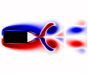
The boat-tail configuration, where fixed flaps are introduced in the rear of the bluff body (Lanser, Ross & Kaufman Reference Lanser, Ross and Kaufman1991), has been extensively studied in the literature. This passive device creates a rear cavity which increases the base pressure and results in a drag reduction by pushing the recirculation bubble downstream and reducing its size (by deflecting the flow inward from the trailing edge), as demonstrated by the experimental and numerical study of Khalighi et al. (Reference Khalighi, Zhang, Koromilas, Balkanyi, Bernal, Iaccarino and Moin2001) and the numerical study of Verzicco et al. (Reference Verzicco, Fatica, Iaccarino, Moin and Khalighi2002). The angle of the flaps can be varied and an optimum angle exists for which the drag reduction is maximum as shown by Browand, Radovich & Boivin (Reference Browand, Radovich and Boivin2005) for field tests with a semitrailer. De la Cruz, Brackston & Morrison (Reference de la Cruz, Brackston and Morrison2017) optimised the lateral flap angles of the flat square-back Ahmed body under cross-wind conditions showing that significant improvement in the drag reduction can be achieved at non-zero yaw angles. Beaudoin & Aider (Reference Beaudoin and Aider2008) experimentally obtained a drag reduction of  $17.6\,\%$ by placing a pair of fixed lateral flaps around the rear slant of a modified Ahmed body at
  $Re=1.4 \times 10^6$, which caused the flow to separate and suppressed the longitudinal vortices.
Successful flow control of turbulent bluff body wakes at high Reynolds numbers has been experimentally obtained through rear forcing applied via harmonically pulsating jets by many researchers. Li et al. (Reference Li, Barros, Borée, Cadot, Noack and Cordier2016) used a feedback controller for the actuated jets in order to symmetrise the turbulent square-back Ahmed body at  $Re=6 \times 10^5$. Li et al. (Reference Li, Borée, Noack, Cordier and Harambat2019) demonstrated that bifrequency control is more effective than the single high-frequency forcing for a square-back Ahmed body and identified that the wake symmetrisation reduces the global production of turbulent kinetic energy in the shear layers. Pastoor et al. (Reference Pastoor, Henning, Noack, King and Tadmor2008) used a zero-net-mass-flux actuation through slots on the upper and lower trailing edges of a D-shaped bluff body for Reynolds numbers ranging between
  $23\,000$ and
  $70\,000$ in order to reduce drag. In-phase forcing synchronised the vortices from the upper and lower edges which significantly delayed the vortex street, increased the base pressure and resulted in considerable drag reduction (
 $15\,\%$). However, the antiphase forcing did not result in an efficient drag reduction. Barros et al. (Reference Barros, Jacques, Noack and Spohn2016a) experimentally forced the turbulent bluff body wake of an Ahmed body by pulsed jets, and identified two resonances. A subharmonic resonance was observed when symmetric forcing was applied and a harmonic one with antisymmetric forcing. Rigas, Morgans & Morrison (Reference Rigas, Morgans and Morrison2017) showed that the subharmonic resonance is due to a triadic interaction between the forcing and the vortex shedding and derived a weakly nonlinear model to capture the behaviour of the forced flow.
Recently, Brackston et al. (Reference Brackston, De La Cruz, Wynn, Rigas and Morrison2016) utilised rear pitching flaps to suppress the symmetry-breaking modes responsible for the bistability of the turbulent Ahmed body wake and obtained a power efficient drag reduction via a feedback controller. The authors also noted that by open loop harmonic forcing, a considerable drag increase could be achieved, and a marginal drag decrease for low frequencies for the specific length of the flaps tested. However, an understanding of the flow mechanisms during the interaction of the pitching flaps with the bluff body wake is lacking, which is a necessary requirement to further improve the aerodynamic performance of bluff bodies.
The flow dynamics past single flapping foils have been extensively studied (Wu et al. Reference Wu, Zhang, Tian, Li and Lu2020) but rarely in the presence of an upstream bluff body wake. For a single pitching foil with high span-to-chord ratio, four different regimes are present depending on the peak-to-peak amplitude of oscillations and the Strouhal number (Godoy-Diana et al. Reference Godoy-Diana, Marais, Aider and Wesfreid2009; Andersen et al. Reference Andersen, Bohr, Schnipper and Walther2017; Lagopoulos, Weymouth & Ganapathisubramani Reference Lagopoulos, Weymouth and Ganapathisubramani2019). In the first regime, characterised by positive drag, the Bénard–von Kármán (BvK) street is observed. In the second regime, characterised by zero drag, the vortices being shed are aligned with respect to the foil span. In the third regime, a reverse BvK appears (De & Sarkar Reference De and Sarkar2021) and in the fourth the reversed BvK street is deflected and an asymmetric wake is produced. The last two regimes are associated with the generation of thrust (propulsion regime). The addition of a second flapping foil (side-by-side) significantly alters the wake dynamics and the propulsive performance (Bao et al. Reference Bao, Zhou, Tao, Peng, Zhu, Sun and Tong2017; Gungor & Hemmati Reference Gungor and Hemmati2020). Martin et al. (Reference Martin, Roh, Idrees and Gharib2017) compared the propulsive performance of the ‘flapping’ motion generated by a single pitching flap and the ‘clapping’ motion generated by periodic contractions of two flaps. The flapping propulsion was identified as the most effective one for Reynolds numbers in the range of  $1880 \le Re \le 11\,260$. However, the effect of the distance between the two flaps on the propulsive performance remains to be in investigated.
In the present study, we investigate the interacting flow dynamics of a bluff body wake generated by a rectangular bluff body with a pair of rear pitching flaps via direct numerical simulations (DNS). This numerical study is focused on low Reynolds numbers  $80 \le Re \le 200$, where the vortex shedding is present but the flow remains laminar. An extensive study of a wide range of the following parameters is performed: aspect ratio of the bluff body; flapping frequency; flap length; pitching amplitude; and Reynolds number. By studying the flapping dynamics in the presence of a laminar bluff body wake, we aim to unravel the fundamental flow mechanisms capable of altering the mean and unsteady drag and lift forces.
The paper is organised as follows. In § 2, the details for the DNS of the flow around the rectangular body with and without flaps are given. Section 3.1 presents the response of the forced flow over a wide range of flapping Strouhal numbers, along with a description of the physical mechanisms responsible for the drag reduction/increase of each forcing strategy. Further, §§ 3.2 and 3.3 cover the effects of the pitching amplitude and Reynolds number dependency, respectively. Section 3.4 proposes a simple scaling parameter of the mean drag reduction based on the geometric and dynamic characteristics of the flaps while § 3.5 examines the performance of each forcing strategy. Finally, the main conclusions are summarised in § 4 along with a description of the future outlook.
2. Numerical modelling
The flow over the rectangular bluff body is described by the incompressible Navier–Stokes equations, solved with high-order finite-difference schemes on a Cartesian mesh. An immersed boundary method is used to represent the effect of the solid boundaries on the fluid. Here, the alternating direction reconstruction immersed boundary method (ADR-IBM) developed by Giannenas & Laizet (Reference Giannenas and Laizet2021) is used. The ADR-IBM allows the simulation of multiple thin and moving boundaries by introducing an extra forcing term  $\boldsymbol {f}$ in the governing equations
 \begin{gather} \frac{\partial \boldsymbol{u}}{\partial t} +\frac{1}{2} [\boldsymbol{\nabla}(\boldsymbol{u} \otimes \boldsymbol{u})+(\boldsymbol{u} \boldsymbol{{\cdot}} \boldsymbol{\nabla})\boldsymbol{u}] +\frac{1}{\rho} \boldsymbol{\nabla} p - \nu \nabla^2 \boldsymbol{u} = \boldsymbol{f}, \end{gather}
 \begin{gather} \boldsymbol{\nabla} \boldsymbol{{\cdot}} \boldsymbol{u} = 0, \end{gather}
where  $\boldsymbol {u}(\boldsymbol {x},t)$ is the velocity field,
  $p(\boldsymbol {x},t)$ is the pressure field,
  $\rho$ is the constant density of the fluid and
  $\nu$ is the kinematic viscosity. The forcing term
  $\boldsymbol {f}$ imposes the required boundary conditions on the velocity field: no-slip boundary condition for the fixed bluff body and a prescribed velocity for the oscillating flaps. Finally, it should be noted that the equations are written in skew-symmetric form in order to reduce aliasing errors (Kravchenko & Moin Reference Kravchenko and Moin1997) and to ensure the conservation of the kinetic energy (in the limit of zero time discretisation error and viscosity).
The high-fidelity open-source flow solver Incompact3d is used for the present simulations. It is one of the high-order finite-difference solvers of the framework Xcompact3d (Bartholomew et al. Reference Bartholomew, Deskos, Frantz, Schuch, Lamballais and Laizet2020) which is dedicated to the study of turbulent flows on a Cartesian mesh. Sixth-order accurate compact finite-difference schemes are employed for the spatial discretisation of the convective and diffusive terms. Their ability to provide accurate results using a moderate number of degrees of freedom when compared with low-order schemes makes them desirable for DNS and large-eddy simulations (LES). A three-step fractional step method is employed for the time integration of the momentum equation (2.1) and a second-order explicit Adams–Bashforth scheme is used for all simulations. In order to obtain the pressure field, a modified (to ensure compatibility with the IBM as detailed in Giannenas & Laizet (Reference Giannenas and Laizet2021)) Poisson's equation is solved in Fourier space on a half-staggered mesh. Strictly equivalent operators to the sixth-order compact schemes (up to machine accuracy) can be defined in Fourier space by leveraging the concept of modified wavenumbers (Lele Reference Lele1992). A validation of the ADR-IBM for the flow over a flat plate undergoing a pitching manoeuvre at  $Re=100$ is presented in Appendix A. A more thorough validation of the ADR-IBM is presented by Giannenas & Laizet (Reference Giannenas and Laizet2021). For further details on the numerical methods implemented in Xcompact3d, the interested reader is referred to Laizet & Lamballais (Reference Laizet and Lamballais2009).
In this study, the velocities are non-dimensionalised with the free stream velocity  $U_\infty$, all lengths with the rectangular body height
  $H_C$, time with
  $U_\infty /H_C$ and frequencies are expressed as Strouhal number
 \begin{equation} St = \frac{f H_C}{ U_\infty}. \end{equation}
The drag and lift coefficients are calculated via a momentum balance in a control volume surrounding the solid body and are defined as
 \begin{equation} C_{D} = \frac{F_D}{\frac{1}{2}\rho U_{ \infty }^{2} H_C}, \quad C_{L} = \frac{F_L}{\frac{1}{2}\rho U_{ \infty }^{2} H_C}, \end{equation}
where  $F_D$ and
  $F_L$ correspond to the drag and lift forces. It should be reported that the size of the control volume used for the calculation of the hydrodynamic coefficients has no influence on the results.
2.1. Natural flow
Here, the natural (unforced) unsteady flow around a rectangular bluff body with varying aspect ratios  $0.25 \le AR=L_C/H_C \le 2.0$ (where
  $L_C$ is the bluff body's length) at a height-based Reynolds number
  $Re = 100$ is studied. At
  $Re_c \sim 46$ (for
  $AR=1$) a Hopf bifurcation gives rise to period vortex shedding (Park & Yang Reference Park and Yang2016; Jiang & Cheng Reference Jiang and Cheng2018; Jiang, Cheng & An Reference Jiang, Cheng and An2018). The flow exhibits a laminar vortex shedding regime at
  $Re_c \lessapprox Re \lessapprox 166$ where the well known von Kármán vortex street can be observed (Sohankar, Norberg & Davidson Reference Sohankar, Norberg and Davidson1998; Bai & Alam Reference Bai and Alam2018). A rectangular computational domain with length
  $L_D=40H_C$ and height
  $H_D=20H_C$ is selected for all simulations. A resolution of
  $n_x \times n_y = 1025 \times 512$ mesh nodes with a stretched mesh in the vertical direction towards the centre of the domain (with the smallest mesh spacing in the vertical direction being
  $\Delta y_{min}=0.026H_C$) is used along with a time step of
  $\Delta t = 5.0 \times 10^{-4}H_C/U_{\infty }$. The selection of the domain size and resolution is based on a convergence study which is presented in the subsequent paragraphs. A uniform velocity is imposed at the inlet and a one-dimensional convection equation is imposed at the outlet which is defined as
 \begin{equation} \frac{\left.\boldsymbol{u}\right|^{t+\Delta t}_{n_{x}} - \left.\boldsymbol{u}\right|^{t}_{n_{x}}}{\Delta t} ={-} U_{\infty} \frac{\left.\boldsymbol{u}\right|^{t}_{n_{x}} - \left.\boldsymbol{u}\right|^{t}_{n_{x-1}}}{\Delta x}, \end{equation}
where  $\boldsymbol {u}|_{n_{x}}$ is the outlet velocity,
  $\boldsymbol {u}|_{n_{x}-1}$ the velocity one mesh node before the outlet and
  $\Delta x$ is the mesh spacing in the streamwise direction. Periodic boundary conditions are imposed in the vertical direction. The velocity flow field is initialised with random noise which follows a Gaussian distribution in space with its peak located at the centre of the domain in the
  $y$ direction (maximum intensity of 0.1 % of
  $U_\infty$). The bluff body is placed at
  $(x_0, y_0)=(10H_C, 10H_C)$ and the simulations are terminated after
  $150$ non-dimensional time-units.
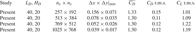
Table 1 summarises the results of a convergence study performed for two different domain sizes ( $L_D, H_D$). In more detail, the mean drag coefficient, lift coefficient r.m.s. (
 $C_L$ r.m.s.) and Strouhal number (
 $St$) are presented for various mesh resolutions and corresponding mesh spacings. As the mesh resolution is increased, a convergence of all quantities can be observed for both computational domain sizes considered. The results obtained with the two finest resolutions are nearly identical for the larger domain (
 $L_D, H_D = 40, 20$). For this study a domain size of
  $L_D, H_D = 40, 20$ and a mesh resolution of
  $n_x \times n_y = 1025 \times 512$ have been selected based on this convergence study.
Mean drag coefficient, root mean square (r.m.s.) lift coefficient and Strouhal number for the flow over a fixed rectangular bluff body ( $AR=1$) at
  $Re=100$ for different domain sizes and mesh resolutions.

Table 2 compares the hydrodynamic coefficients and Strouhal numbers obtained in the present study with the values reported in the literature for the natural flow over a rectangular bluff body with an aspect ratio  $AR=1$ at
  $Re = 80\unicode{x2013}200$. The mean drag coefficient, lift coefficient r.m.s. and Strouhal numbers are in good agreement with the results reported in the literature for all Reynolds numbers considered in the present study.
Mean drag coefficients, lift coefficient r.m.s. and Strouhal numbers for the flow over a rectangular bluff body ( $AR=1$) at
  $80 \le Re \le 200$.
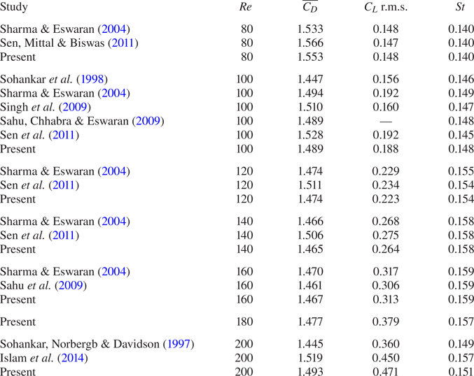
Figure 1 compares the evolution of the Strouhal number,  $\overline {C_D}$ and
  $C_L$ r.m.s. for a wide range of aspect ratios
  $0.25 \le AR \le 4.0$ with the results reported by Yang & Wu (Reference Yang and Wu2013), Islam et al. (Reference Islam, Zhou, Shah and Xie2012) and Sohankar et al. (Reference Sohankar, Norbergb and Davidson1997). Again, the mean drag, lift r.m.s. and Strouhal number are in good agreement with the reported studies.
Strouhal number (a), mean drag coefficient (b) and lift coefficient r.m.s. (c) against aspect ratio  $AR$, for the unforced flow around a rectangular bluff body at
  $Re=100$.

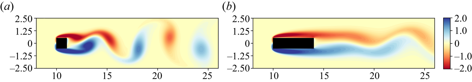
Furthermore, figure 2 shows instantaneous vorticity contours at  $t=150$ for aspect ratios
  $AR=1$ and
  $AR=4$. By increasing the aspect ratio, the shed vortices are weakened and the dead water (recirculation) region is increased, which results in an increase in the base pressure (Sohankar et al. Reference Sohankar, Norbergb and Davidson1997) and a subsequent drag reduction.
Instantaneous vorticity contours for the unforced flow over a rectangular bluff body at  $Re=100$ with aspect ratios
  $AR=1$ (a) and
  $AR=4$ (b) at time
  $t=150$.
To identify the forced flow mechanisms giving rise to a drag reduction (which will be presented in the subsequent sections), we have calculated the reference drag reduction that can be achieved by solely eliminating the vortex shedding. This will be used as a reference in cases where the forcing is sufficiently strong, in order to symmetrise the flow by suppressing the vortex shedding. In the absence of forcing, the mean drag can be decomposed into the base flow drag (the drag of the bluff body at the same Reynolds number with a steady and  $y$-symmetric flow) and the shedding induced drag as described by Protas & Wesfreid (Reference Protas and Wesfreid2002). In this context, the maximum (reference) drag reduction that can be achieved by the elimination of the vortex shedding is limited by the symmetric base drag at the same Reynolds number (i.e. by the drag of the base flow which is linearly unstable above
  $Re_c$). In order to identify this limit, simulations of the flow over a rectangular bluff body with aspect ratios
  $AR=1,2,4$ are performed with the aforementioned set-up with the exception that no numerical noise is used for the initialisation of the velocity flow field. Since no disturbance is added into the flow at the start of the simulation to trigger vortex shedding, the flow remains steady and symmetric. The accumulation of numerical errors will eventually trigger the instability but this only happens well after the symmetric flow is effectively converged.
The drag coefficients obtained with the steady symmetric flow for  $AR=1,2,4$ at
  $Re=100$ are
 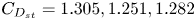 $C_{D_{st}} = 1.305, 1.251, 1.282$, respectively. By comparing the steady coefficients with the mean drag of the natural flow for each aspect ratio (
 $\overline {C_{D_{0}}} = 1.489, 1.339, 1.304$) the maximum (reference) drag reductions based on a wake symmetrisation technique are
  $\Delta C_{D_{sym}} = (\overline {C_{D_{0}}}-C_{D_{st}}) / \overline {C_{D_{0}}} = 12.4\,\%, 6.6\,\%, 1.7\,\%$, respectively. As can be observed, the maximum drag reduction with a wake symmetrisation technique becomes smaller with increasing
  $AR$. In the case of full elimination of the vortex shedding, any further deviations from the base flow drag are primarily attributed to mean flow modifications due to the flapping motion.
2.2. Forced flow
Here, the different forcing strategies are presented. The harmonic forcing is applied by two, thin and pitching flaps attached to the rear of the body. Figure 3 shows the three flap motions considered, with the flow going from left to right. In the ‘snaking’ motion, both flaps move in-phase and in the same direction (sinuous mode). Contrarily, the flaps move in opposite directions (out-of-phase) to create the ‘clapping’ motions (varicose mode). Here, two out-of-phase clapping motions are considered: full clapping (FC), where the flaps exceed the vertical level of the bluff body and penetrate the free shear layer (which develops over the upper and lower sides of the body); and constrained clapping (CC), where the flaps are not allowed to penetrate the free shear layer.
Schematic demonstrating the in-phase snaking (a), full clapping (FC) (b) and constrained clapping (CC) (c) motions. The flow is going from left to right.
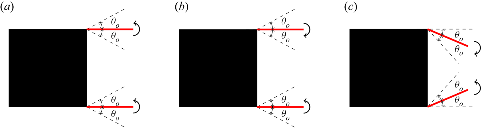
In all cases, the flaps follow a harmonic pitching motion. The instantaneous flap angle  $\theta (t)$ of the top and bottom flaps for the snaking, FC and CC motions is described as
 \begin{equation} \left. \begin{aligned}
\text{snaking}\quad \theta = & \begin{cases}
\theta_{o} \sin(2 {\rm \pi}\, St_f \, t), & \text{top flap} \\
\theta_{o} \sin(2 {\rm \pi}\, St_f \, t), & \text{bottom flap}
\end{cases} \\ \text{FC}\quad \theta = & \begin{cases}
\theta_{o} \sin(2 {\rm \pi}\, St_f\, t), & \text{top flap} \\ -
\theta_{o} \sin(2 {\rm \pi}\, St_f \, t), & \text{bottom flap}
\end{cases} \\ \text{CC}\quad \theta = & \begin{cases}
\theta_{o} \sin(2 {\rm \pi}\, St_f \, t) - \theta_{o}, &
\text{top flap} \\ - \theta_{o} \sin(2 {\rm \pi}\, St_f\, t) -
\theta_{o}, & \text{bottom flap} \end{cases} \end{aligned}
\right\} \end{equation}
\begin{equation} \left. \begin{aligned}
\text{snaking}\quad \theta = & \begin{cases}
\theta_{o} \sin(2 {\rm \pi}\, St_f \, t), & \text{top flap} \\
\theta_{o} \sin(2 {\rm \pi}\, St_f \, t), & \text{bottom flap}
\end{cases} \\ \text{FC}\quad \theta = & \begin{cases}
\theta_{o} \sin(2 {\rm \pi}\, St_f\, t), & \text{top flap} \\ -
\theta_{o} \sin(2 {\rm \pi}\, St_f \, t), & \text{bottom flap}
\end{cases} \\ \text{CC}\quad \theta = & \begin{cases}
\theta_{o} \sin(2 {\rm \pi}\, St_f \, t) - \theta_{o}, &
\text{top flap} \\ - \theta_{o} \sin(2 {\rm \pi}\, St_f\, t) -
\theta_{o}, & \text{bottom flap} \end{cases} \end{aligned}
\right\} \end{equation}
where  $\theta _{o}$ is the flapping amplitude and
  $St_f$ the flapping frequency, non-dimensionalised with the body height and free stream velocity. Further, the length of the flaps
  $l_f$ is non-dimensionalised with the bluff body height. A constant flap thickness of
  $5\,\%$ of the bluff body height is considered, as it is a good compromise between an appropriate time to solution (170 CPU hours on a single core) and the required mesh resolution to accurately capture the fluid motions close to the flaps (600 simulations have been performed for this numerical study).
Table 3 summarises a convergence study for the forced flow over a rectangular bluff body with  $AR=4$,
  $l_f=0.6$,
  $St_f=0.30$ with the in-phase snaking motion and a time step of
  $\Delta t = 5.0 \times 10^{-4}H_C/U_{\infty }$. The values of the mean and r.m.s. force coefficients change less than 2.5 % between the two finest resolutions. For this study, the finest resolution of
 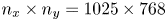 $n_x \times n_y = 1025 \times 768$ is selected along with a domain size of
  $L_D \times H_D = 40 H_C \times 20 H_C$.
Mean and r.m.s. aerodynamic force coefficients with in-phase snaking forcing for various mesh resolutions ( $AR=4$,
  $Re=100$,
  $l_f=0.6$,
  $St_f=0.30$).
3. Results
3.1. Frequency response
Here, the response of the bluff body wake to in-phase snaking and out-of-phase clapping harmonic forcing is studied for a wide range of flapping Strouhal numbers. Results are shown for a constant amplitude of flap oscillations ( $\theta _{o}=20 ^{\circ }$), for different flap lengths (
 $l_f = 0.4,0.6,0.8,1.0$) and bluff body aspect ratios (
 $AR=1,2,4$). The flap length for the constrained clapping is limited to
  $l_f=0.4,0.6$ to avoid the collision of the top and bottom flaps.
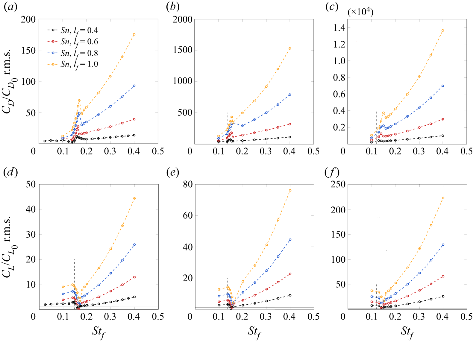
3.1.1. Snaking motion
Figures 4 and 5 show the periodic steady-state response to snaking of the normalised r.m.s. of the lift and drag and mean drag coefficients. The mean drag coefficient has been normalised by the mean drag coefficient of the natural flow  $\overline {C_{D_{0}}} = 1.489, 1.339, 1.304$ for
  $AR=1,2,4$, respectively. Similar normalisations are performed for the r.m.s. values. Two regimes can be identified based on the mean drag: a drag reduction regime and a drag increase one.
Normalised r.m.s. of the drag (a–c) and lift (d–f) coefficients for in-phase snaking for a range of flapping frequencies  $St_f$. Here,
  $AR=1$ (a,d),
  $AR=2$ (b,e) and
  $AR=4$ (c, f), each for different flap lengths
  $l_f$. The vertical dashed lines indicate the natural Strouhal number.
Normalised mean drag coefficients for in-phase snaking for a range of flapping frequencies  $St_f$. Here,
  $AR=1$ (a),
  $AR=2$ (b) and
  $AR=4$ (c), each for different flap lengths
  $l_f$. The vertical dashed lines indicate the natural Strouhal number.

A distinct peak on the drag r.m.s. and a trough on the lift r.m.s. occur when forcing is applied near the Strouhal number of the natural flow  $St_0 = 0.148, 0.136, 0.12$ for
  $AR=1,2,4$, respectively. This is the result of a fundamental resonance which arises from the interaction between the antisymmetric oscillatory vortex shedding mode and the antisymmetric flap oscillation, which induces an amplification of the vortex shedding mode. The resonance is termed fundamental since the natural vortex shedding instability and the forcing are at the same frequency and share the same symmetry. A similar sharp peak is present on the mean drag which corresponds to a significant drag increase (of more than
  $40\,\%$ for some cases). The mean flow modification, or equivalently the mean drag increase, is a second-order effect arising from the nonlinear interactions of the forcing and shedding mode (see, for example, Sipp (Reference Sipp2012) for their prediction based on a weakly nonlinear expansion). Increasing the flap length results in an increase in the peak magnitude of the mean and r.m.s. of the drag coefficient (for
  $AR=2$,
  $\overline {C_D}/\overline {C_{D_{0}}} = 1.09, 1.50$ with
  $l_f=0.4,1.0$, respectively). The increase by an order of magnitude of the drag r.m.s. when the aspect ratio is doubled, is a direct consequence of the behaviour of the natural flow where the drag r.m.s. decreases by an order of magnitude each time the aspect ratio is doubled (
 $C_{D_{0}} \textrm { r.m.s.} = 4.9 \times 10^{-3}, 5.6 \times 10^{-4}, 5.9 \times 10^{-5}$ for
  $AR=1,2,4$, respectively).
Figure 6 shows instantaneous vorticity contours for the forced flow with in-phase snaking motion for  $AR=1$ and
  $l_f=0.6$ at different flapping Strouhal numbers. At
  $St_f=0.165$, where the fundamental resonance occurs, the vortex shedding amplification can be observed along with a considerable increase in the vorticity magnitude (compared with smaller and larger flapping Strouhal numbers and to the natural flow). The drag r.m.s. peak is the result of the vortex shedding amplification. The amplified vortices result in a large pressure drop on the body's rear surface which is discussed in further detail in Appendix D.
Instantaneous vorticity fields at  $t=5T/8$ with in-phase snaking motion for a range of flapping frequencies (
 $AR=1$,
  $Re=100$,
  $l_{f}=1.0$). The vorticity field of the natural flow is repeated in panel (c) for comparison.

The fundamental resonance mechanism has been identified previously in fully turbulent regimes. Barros et al. (Reference Barros, Jacques, Noack and Spohn2016a) observed a similar harmonic resonance of the antisymmetrically forced via pulsed jets turbulent wake over an Ahmed body at  $3 \times 10^{5} \le Re \le 6 \times 10^{5}$, which amplified the vortex shedding. Similarly, in the experimental study of Pastoor et al. (Reference Pastoor, Henning, Noack, King and Tadmor2008), where the turbulent wake of a D-shaped body was harmonically forced by loudspeakers at
  $23\,000 \le Re \le 70\,000$, a fundamental resonance resulted in a sudden drop of the base pressure, producing a significant drag increase.
The resonant peaks/troughs in figures 4 and 5 do not occur exactly at the natural Strouhal number  $St_0$. Instead, they are shifted towards higher Strouhal numbers. Further, stronger shifts are exhibited with the increase in the forcing due to the increasing flap length. As an example, for
  $AR=1$, the mean drag peak is located at
  $St_f \thickapprox 0.155$ when
  $l_f=0.4$ and at
  $St_f \thickapprox 0.165$ for
  $l_f = 1.0$. The shift of the peaks is typical of nonlinear oscillators forced near their fundamental primary resonant frequency (see Kovacic & Brennan (Reference Kovacic and Brennan2011) for further details) and has also been observed in turbulent regimes for three-dimensional bluff bodies in experiments by Brackston et al. (Reference Brackston, De La Cruz, Wynn, Rigas and Morrison2016). The nonlinear shift of the peaks can also be predicted by the forced Stuart–Landau equation as it has been demonstrated by Le Gal, Nadim & Thompson (Reference Le Gal, Nadim and Thompson2001) and Rigas et al. (Reference Rigas, Morgans and Morrison2017).
Considerable drag reductions  $(\overline {C_{D_{0}}}-\overline {C_{D}}) / \overline {C_{D_{0}}} = 26.5\,\%, 18.2\,\%,12.0\,\%$ for
  $AR=1,2,4$, respectively, can be obtained by all flap lengths for all three aspect ratios, as observed in figure 5. For small flapping Strouhal numbers away from the resonant region,
  $St_f \le St_0$, a small drag reduction is achieved solely for
  $AR=1$ for the range of frequencies examined. Contrarily, at high Strouhal numbers a drag reduction is obtained for all aspect ratios and flap lengths, with larger flaps resulting in larger drag reductions. Figure 6 for
  $St_f=0.20,0.40$ indicates that a gradual symmetrisation of the wake by the stabilisation of the unsteady vortex shedding, is responsible for the observed drag reduction. However, the drag reductions observed in figure 5 are greater than the maximum (reference) drag reduction allowed by the symmetrisation of the wake
  $\Delta C_{D_{sym}}$ (see § 2.1). Hence, the excess drag reduction beyond the symmetrised regime can be attributed to a propulsion mechanism due to the thrust produced by the pitching flaps (Gazzola, Argentina & Mahadevan Reference Gazzola, Argentina and Mahadevan2014). The thrust generated by the flaps is due to the acceleration of a mass of fluid which by action/reaction propels the bluff body in the opposite direction and reduces its mean drag (Floryan, Van Buren & Smits Reference Floryan, Van Buren and Smits2019).
In order to gain insight into the wake symmetrisation mechanism, instantaneous vorticity contours at various phases of the snaking motion with  $AR=4$,
  $l_{f}=1.0$ and
  $St_f=0.40$ are presented in figure 7. For these forcing parameters, the wake symmetrisation extends
  ${\sim }13H_C$ body heights downstream. The method used for the calculation of the extent of the wake symmetrisation is presented in Appendix C. During a flap oscillation cycle, alternating shedding of two vortex dipoles (VDs) is observed. One VD is formed on and shed from the top flap and another from the bottom flap.
Instantaneous vorticity fields with the in-phase snaking motion for a range of flap phases ( $AR=4$,
  $Re=100$,
  $l_{f}=1.0$,
  $St_f=0.40$).

In the following, we focus on the description of the formation of the dipole from the bottom flap only, since the same process is followed from the top flap with a time lag  $T/2$. At
  $t=T/4$ the bottom flap is in its uppermost position. As the bottom flap starts moving downwards,
  $T/4 < t < 3T/4$, two counter-rotating vortices are generated. A primary bluff body vortex
  $V_1$, shown in blue, is created as the flap pitches against the free shear layer which has been developed on the lower side of the bluff body (see
  $t=T/2$). A secondary flap vortex
  $V_2$, shown in red, is also created on the upper side of the bottom flap due to the flap pitching motion (see
  $t=3T/8$). As the bottom flap continues its downward motion, both vortices grow in size and intensity. After
  $t=3T/4$, the flap's motion is reversed and the flap starts moving upwards. Due to this reversal, the secondary vortex
  $V_2$ rolls off the bottom flap (see
  $t=7T/8$). At
  $t=T$ both the primary and secondary vortices are ejected, thus creating a VD (i.e. a counter-rotating vortex pair). The same process is repeated with the upper flap, which leads to the ejection of the second VD at
  $t=T/2$.
The secondary vortex  $V_2$ plays a crucial role in the wake symmetrisation as it considerably weakens the primary vortex
  $V_1$ which is responsible for the vortex shedding. Hence, the extent of the wake symmetrisation is highly dependent on the intensity of the secondary vortex, compared with the intensity of the corresponding primary one. The intensity of the secondary vortex is dependent on the strength of the forcing (i.e. flap length and flapping Strouhal number) whereas it remains largely unaffected by the aspect ratio of the body. When the forcing is weak (see figure 6 for
  $St_f=0.20$) the primary vortex dominates over the considerably weaker secondary one. Contrarily, the intensity of the primary vortex decreases significantly with increasing aspect ratio. The weaker primary vortices generated by larger aspect ratios allow the wake to be symmetrised with weaker forcing by the flaps (see figure 6 for
  $St_f=0.40$ and figure 7 for comparison).
In summary, the forced bluff body wake with the in-phase snaking motion results in two flow regimes. The first regime corresponds to a gradual wake symmetrisation, the extent of which is dependent on the amplitude of the forcing. For flapping Strouhal numbers smaller and away from the resonant range, the weak forcing is insufficient to alter the vortex shedding of the bluff body. For  $St_f > St_0$, the strong forcing exerted by the flaps generates a VD which eventually leads to the symmetrisation of the wake (the extent of which depends on the exact set-up) and significant drag reduction. In the second regime, the forcing enhances the vortex shedding through a resonance mechanism which results in a substantial drag increase. The resonance occurs near the Strouhal number of the natural (unforced) flow
  $St_0$.
3.1.2. Clapping motion
Figures 8 and 9 show the frequency response to harmonic out-of-phase forcing with the FC and CC motions of the mean drag and lift/drag r.m.s. coefficients. Contrary to the snaking motion, no harmonic resonance is observed when forcing near the Strouhal number of the natural flow. Instead, a subharmonic resonance of the vortex shedding can be identified as a distinct peak on the lift r.m.s. coefficient and subsequently on the mean drag when the forcing is applied near twice the vortex shedding frequency of the natural flow,  $St_f\approx 2 St_0$. The subharmonic resonance is identified for both the FC and CC motions. However, the r.m.s. and mean CC resonant amplitudes are considerably smaller compared with the FC ones. Interestingly, no peak is present on the drag coefficient r.m.s. The resonant peaks observed on the mean drag coefficient near
  $2St_0$ have smaller amplitudes compared with the harmonic resonance ones (see figures 5 and 9), indicating that the fundamental resonance mechanism is more efficient in amplifying the vortex shedding mode compared with the parametric subharmonic one.
Normalised r.m.s. of the drag (a–c) and lift (d–f) coefficients for the out-of-phase clapping for a range of flapping frequencies  $St_f$. Here,
  $AR=1$ (a,d),
  $AR=2$ (b,e) and
  $AR=4$ (c, f), each for different flap lengths
  $l_f$. The vertical dashed lines indicate the natural Strouhal number times two.

Normalised mean drag coefficients for out-of-phase clapping for a range of flapping frequencies  $St_f$. Here,
  $AR=1$ (a),
  $AR=2$ (b) and
  $AR=4$ (c), each for different flap lengths
  $l_f$. The vertical dashed lines indicate the natural Strouhal number times two.

The parametric subharmonic instability has been observed in forced transitional and turbulent regimes. Williams, Mansy & Amato (Reference Williams, Mansy and Amato1992) reported the existence of a subharmonic resonant interaction between symmetric unsteady bleed forcing and the primary vortex shedding mode for the flow past a circular cylinder at  $Re=470$ when the wake was forced at twice the frequency of the natural flow. Similar resonances are also observed in both circular and square cylinders undergoing forced streamwise oscillations (Tudball-Smith et al. Reference Tudball-Smith, Leontini, Sheridan and Jacono2012). Barros et al. (Reference Barros, Jacques, Noack and Spohn2016a) also observed a subharmonic resonance at twice the vortex shedding frequency of the unforced flow which was associated with a base pressure drop and an increase in the pressure drag for the turbulent forced flow over an Ahmed body at
  $3 \times 10^{5} \le Re \le 6 \times 10^{5}$ when symmetric forcing was applied. This subharmonic resonance was attributed to an amplification of the global oscillatory mode of the laminar regime which persists at high Reynolds numbers. Rigas et al. (Reference Rigas, Morgans and Morrison2017) observed a similar subharmonic resonance when the turbulent wake of an axisymmetric bluff body with a blunt trailing edge at
  $Re = 1.88 \times 10^5$ was forced at twice the shedding frequency with axisymmetric blowing/suction. This parametric subharmonic resonance, which occurs when the frequency of the global mode locks-in to one half of the driving frequency, was attributed to a nonlinear triadic interaction between the forcing and the shedding. Herrmann et al. (Reference Herrmann, Oswald, Semaan and Brunton2020) experimentally examined the forced flow over a D-shaped bluff body with periodic blowing at
  $Re=5.62 \times 10^{4}$ and confirmed the triadic subharmonic resonant interaction which occurred when symmetric forcing was applied. Even though the above studies apply jet forcing to excite the wake, the resonant response of the antisymmetric vortex shedding mode depends on the spatial symmetry of the forcing regardless of the means through which the perturbation was generated (flaps or jets). In fact, equivalent resonances between the driving and global frequencies have also been observed for inline oscillating circular cylinders (Leontini, Jacono & Thompson Reference Leontini, Jacono and Thompson2011).
Figure 10 shows instantaneous vorticity contours for  $AR=1$,
  $l_f=0.6$ for various Strouhal numbers before, at and after the subharmonic resonance with the FC and CC motions. Similar to the snaking motion, a secondary flap vortex with opposite vorticity with respect to the primary bluff body vortex is generated and a VD emerges. For
  $St_f=0.15$, the secondary vortices are weak and the primary vortices dominate the flow. With the increase in the flapping Strouhal number to
  $St_f = 0.25$ (i.e. increase in the forcing) the intensity of the secondary vortices increases, which results in the symmetrisation of the near wake. Consequently, a modest (
 ${\sim }10\,\%$) mean drag reduction is achieved (see figure 9). Near the subharmonic resonance at
  $St_f=0.29 \simeq 2 St_0$, the vortex shedding is amplified, which results in a considerable increase in the lift r.m.s. (see figure 8) and a subsequent increase in the mean drag. Due to the symmetry of the forcing, the subharmonic resonance cannot amplify the vortex shedding as effectively as the fundamental resonance. This is evident by the relatively weaker vortices produced by the flaps (see the corresponding figure for the instantaneous pressure contours presented in Appendix D). These vortices cannot produce a large enough pressure drop on the body's rear surface. Hence, the subharmonic resonance does not produce a drag r.m.s. peak. Finally, at
  $St_f=0.40$ the wake symmetrisation extends farther downstream of the flaps and results in a subsequent reduction in the mean drag (
 ${\sim }20\,\%$) and lift r.m.s.
Instantaneous vorticity field with out-of-phase FC at  $t=T/2$ (a–d) and CC at
  $t=T/4$ (e–h) for a range of flapping frequencies (
 $AR=1$,
  $Re=100$,
  $l_{f}=0.6$).

For the CC motion, minimal differences in the vorticity fields are observed between  $St_f=0.15$ and
  $St_f=0.29$. Since the flaps do not interact with the high-speed shear layer regions due to their angular constraint within the recirculation region, the resonant peaks at
  $St_f\simeq 2St_0$ are significantly smaller than the ones observed for the FC motion. For frequencies
  $St_f>2St_0$, the CC results in higher drag reduction compared with the FC motion for all aspect ratios and flap lengths considered. This is demonstrated at
  $St_f=0.40$ where the wake symmetrisation effect is more pronounced for the CC than for the FC motion.
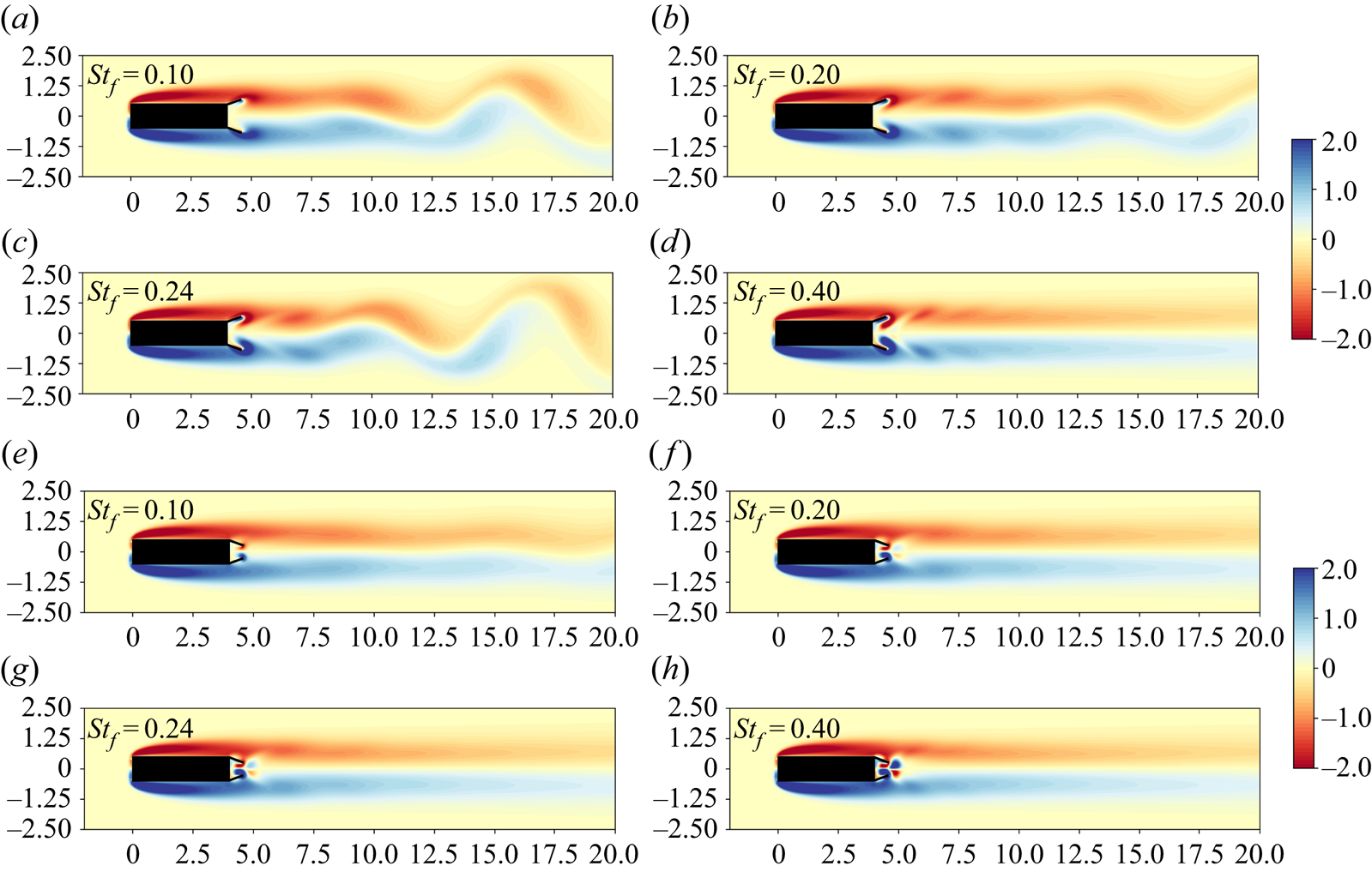
Figure 11 shows instantaneous vorticity contours for the FC and CC motions with  $AR=4$ and
  $l_f=0.6$ for various flapping Strouhal numbers. For the FC motion, a weak symmetrisation of the wake is observed for
  $St_f=0.10$ and
  $St_f=0.20$, accompanied by drag reduction. When forcing at twice the shedding frequency,
  $St_f=0.24$, the subharmonic resonant effect can be observed through the enhancement of the vortex shedding mode, which results in the increased mean drag coefficient but still an overall drag reduction. Finally, at
  $St_f=0.40$ the wake is symmetrised, resulting in a significant drag reduction. For the CC motion on the other hand, the wake has been fully symmetrised at
  $St_f=0.20$. Hence, there is no enhancement of the primary vortex shedding mode at
  $St_f=0.24$ as it has been fully suppressed.
Instantaneous vorticity field with out-of-phase FC at  $t=T/4$ (a–d) and CC at
  $t=T/2$ (e–h) for a range of flapping frequencies (
 $AR=4$,
  $Re=100$,
  $l_{f}=0.6$).
The subharmonic resonance (see mean drag coefficient in figure 9) disappears by increasing the flap length for all aspect ratios considered. The extension of the flap length increases the effective aspect ratio of the bluff body, which reduces the vortex shedding amplitude and consequently the resonant interaction with the forcing. As shown in § 2.1, the natural vortex shedding in the absence of forcing is weakened by increasing the aspect ratio of the bluff body. Further, due to the weakened vortex shedding, the clapping motion is capable of symmetrising the wake and eliminating the global instability entirely with weaker forcing when larger flap lengths are considered. Hence, as the flap length is increased, the resonant peaks become smaller in amplitude due to the gradual symmetrisation of the wake. Eventually, the subharmonic resonance cannot occur as the vortex shedding instability has been suppressed. The resonant peaks observed with the constraint clapping motion are significantly smaller than the ones with the FC motion. Since the flaps with the FC motion can penetrate the high-speed region of the shear layer, intense primary vortices are generated which require secondary vortices with the same intensity for the symmetrisation of the wake.
Similar to the snaking motion, two VD are being shed by the flaps in each cycle. However, unlike the snaking which resulted in the asynchronous shedding of the dipoles at  $t=T/2, T$ the clapping motion results in the simultaneous ejection of both dipoles at
  $t=T/2$ as shown in figure 12 for the FC motion with
  $AR=2$,
  $l_f=1.0$ and
  $St_f=0.40$. These parameters correspond to a drag reduction of more than
  $80\,\%$. The mechanisms which give rise to the primary (bluff body) and secondary (flap) vortices remain the same as those described for the snaking motion.
Instantaneous vorticity field with out-of-phase CC motion for a range of flap phases ( $AR=2$,
  $Re=100$,
  $l_{f}=1.0$,
  $St_f=0.40$).

In summary, the forced bluff body wake with the clapping motion results in two flow regimes. The first regime corresponds to wake symmetrisation, the extent of which depends on the strength of the forcing. In this regime, drag reduction is achieved for almost all aspect ratios and flap lengths apart from cases where the forcing is very weak (small flap length and  $St_f$). The second regime is related to the nonlinear triadic resonant interaction between the forcing and the primary vortex shedding instability which occurs at twice the natural Strouhal number
  $2 St_0$. Even though the mean drag exhibits a resonant peak, drag reduction is still observed for most aspect ratios and flap lengths. Both FC and CC motions result in drag savings much greater than the maximum (reference) drag reduction which can be achieved by a wake symmetrisation mechanism (see § 2.1). Hence, any further drag reduction than
  $\Delta C_{D_{sym}}$, is is attributed to propulsion mechanisms.
3.1.3. Wake profiles
The wake velocity profiles are shown in figure 13 for the snaking and FC motions in order to quantify the effect of the forcing on the base flow and clarify the propulsion mechanism that results in considerable mean drag reduction.
Time-averaged streamwise velocity profiles with the snaking (a) and FC (b) motions. The solid lines correspond to the forced flow and the dashed ones to the natural one. Time-averaged streamwise velocity difference profiles between forced and natural cases with snaking (c) and FC (d). Here  $AR=4$,
  $l_f=1.0$,
  $St_f=0.40$.
Figure 13(a,b) compares the time-averaged streamwise velocity profiles along the vertical direction of the natural flow (dashed lines) with the ones of the forced flow (solid lines) by the snaking and FC motions with  $AR=4$,
  $l_f=1.0$,
  $St_f=0.40$. In figure 13(c,d) the natural velocity profiles are subtracted from the forced ones in order to extract the mean flow modification due to the forcing. The snaking motion for this case corresponds to a drag reduction of
  $12\,\%$ whereas the FC to a drag reduction of
  $75\,\%$. As it can be observed in the figure, the snaking motion does not affect the Blasius-like profile which develops over the length of the body, whereas the clapping motion produces a very small modification near the flaps.
Both motions result in a significant modification of the wake profiles for a short distance downstream of the flaps ( ${\sim }1.5 H_c$). Further, the forced flow produces a larger wake deficit than the natural flow at the centreline of the body (
 $y=0$) just downstream of the flaps. This is the result of the strong primary vortices which are generated when the flaps reach their maximum amplitude at
  $t=T/4,3T/4$ for the snaking and at
  $t=T/4$ for the FC motion. As the flaps move back towards the
  $\theta =0 ^{\circ }$ position, a secondary and counter-rotating vortex is generated which is shed at
  $t=T/2,T$ for the in-phase and at
  $t=T/2$ for the out-of-phase motions. The pair of the counter-rotating vortices is propelled downstream and accelerates the flow. This results in a decrease in the drag deficit near the maximum position of the flaps which is observed in figure 13. In the region after two body-heights (
 $2H_c$) downstream of the flaps, the forced profiles generated with the snaking motion are nearly identical to the natural ones. Contrarily, the effects of the forcing for the FC motion persist (even up to four body-heights downstream of the flaps) and produce a significantly smaller drag deficit.
Regardless of the forcing strategy, each flap generates a single jet-like profile which is very similar to the velocity profiles of single pitching foils (Van Buren et al. Reference Van Buren, Floryan, Wei and Smits2018). The jet profiles indicate the existence of the reverse BvK vortex street produced by each pitching flap (Taylor Reference Taylor2018). The snaking motion results in a velocity profile with only two peaks which accelerate the flow for a short distance downstream of the flaps. Contrarily, the contracting motion of the flaps with the out-of-phase clapping motion results in a pressure increase inside the cavity which leads to a high-speed ejection of fluid at the centreline (see figure 12 at  $t=5T/8$). This creates a third peak in the velocity profiles which is maintained for a long distance downstream of the flaps. No wake deflection (similar to the one observed for by Godoy-Diana et al. (Reference Godoy-Diana, Marais, Aider and Wesfreid2009) for a single flapping foil and by Gungor & Hemmati (Reference Gungor and Hemmati2020) for side-by-side foils) has been observed for either the snaking or clapping motions.
The thrust produced by the pitching flaps is a direct consequence of the jet-wakes which are characterised by a reverse BvK vortex street (see figure 1c in Taylor (Reference Taylor2018)). The fact that the jet profiles for the clapping persist farther downstream than the snaking ones, suggests that the clapping motion is more effective compared with the snaking one in producing high thrust in order to considerably reduce the mean drag once the wake has been fully symmetrised. This is in line with the observations of Dewey et al. (Reference Dewey, Quinn, Boschitsch and Smits2014) who noted that in-phase oscillating side-by-side hydrofoils exhibit enhanced propulsive efficiency and reduced thrust whereas out-of-phase ones exhibit enhanced thrust while maintaining their propulsive efficiency. At this point it should be noted that the flaps do not generate enough propulsive forces in order to produce a net thrust (i.e. the drag ratio does not become negative) for the range of parameters studied (see figures 5 and 9).
3.2. Amplitude response
Here, the effect of the forcing amplitude  $\theta _{o}$ is investigated for various aspect ratios and a fixed flap length of
  $l_f=0.6$ with the snaking and clapping motions. A wide range of amplitudes (
 $5^{\circ } \le \theta _{o} \le 35 ^{\circ }$) is studied for two flapping Strouhal numbers (snaking –
  $St_f|_{AR=1}=0.16,0.30, St_f|_{AR=2}=0.145,0.30, St_f|_{AR=4}=0.14,0.30$; clapping –
  $St_f|_{AR=1}=0.28,0.35, St_f|_{AR=2}=0.26,0.35, St_f|_{AR=4}=0.24,0.35$). The selected frequencies cover both the nonlinear resonant regions (harmonic for the snaking and subharmonic for the clapping) where significant drag increase is observed and the regions where drag reduction through the wake symmetrisation and propulsion mechanisms is achieved.
Figure 14, shows the response of the mean drag for different forcing amplitudes and frequencies. When forcing of small amplitude ( $5 ^{\circ } \le \theta _{o} \le 10 ^{\circ }$) is applied with the snaking motion near the fundamental frequency
  $St_f=0.16$ for
  $AR=1$, the mean drag shows very small variations. However, as the amplitude is increased for
  $\theta _{o} \ge 15 ^{\circ }$, the drag ratio increases rapidly, suggesting that a minimum threshold exists below which the flow cannot lock-in the frequency of the vortex shedding in order to interact with the primary instability and enhance it (i.e. for the fundamental resonance to occur). Brackston et al. (Reference Brackston, De La Cruz, Wynn, Rigas and Morrison2016) and Rigas et al. (Reference Rigas, Morgans and Morrison2017) noted a similar threshold in turbulent forced wakes.
Normalised mean drag coefficient with  $AR=1$ (a),
  $AR=2$ (b) and
  $AR=4$ (c) for a range of forcing amplitudes
  $\theta _{o}$ with in-phase snaking and out-of-phase clapping motions. The solid horizontal lines correspond to a unity ratio.

Regarding the clapping motions, when the excitation is applied near/at twice the frequency of the natural flow (subharmonic resonance),  $St_f = 0.28, 0.265, 0.24$ for
  $AR=1,2,4$, respectively, the mean drag ratio remains almost constant for a wide range of amplitudes and eventually starts decreasing for
  $\theta _{o} \gtrsim 25 ^{\circ }$. The fact that the mean drag does not increase with increasing amplitude may appear counter-intuitive but can be explained when the competing mechanisms of the nonlinear subharmonic resonance and the drag reduction mechanisms of propulsion and wake-symmetrisation are considered. While the subharmonic triadic resonance attempts to increase the drag, the increased forcing (due to the increased amplitude) counteracts this effect via the propulsion and wake symmetrisation mechanisms. This competition is also (partly) responsible for the transition of the mean drag peaks to smoothed humps and eventually their complete elimination that was observed in figure 9.
3.3. Reynolds number dependence
In this section the Reynolds number dependence of the forced flow with the snaking and clapping motions is evaluated. First, the dependence is investigated for a fixed aspect ratio  $AR=1$, flap length
  $l_f=0.6$ and flapping Strouhal number
  $St_f=0.40$ with the snaking, FC and CC motions for
  $80 \le Re \le 200$. The mean drag ratio between forced and natural cases presented in figure 15 shows a favourable decrease as
  $Re$ increases for all three motions.
(a) Mean drag ratio for a range of Reynolds numbers for  $AR=1$, with the snaking and clapping motions at
  $St_f=0.40$ with various flap lengths. (b,c) Instantaneous vorticity fields at
  $t=T$ with out-of-phase FC motion (
 $AR=1$,
  $Re=80$ (b) and
  $Re=120$ (c),
  $l_{f}=0.8$).

The decrease of the mean drag ratio is the result of the increase of the thrust generated by the flaps with increasing  $Re$. In order to illustrate this, let us consider the case of the FC motion for
  $AR=1$,
  $l_f=0.8$ where drag ratios of
  $\overline {C_{D}} / \overline {C_{D_{0}}}=0.65,0.49$ are obtained for
  $Re=80\,120$, respectively. For this case it can be deduced that the drag of the natural flow does not contribute to the decrease of the drag ratio as its value at
  $Re=120$ is lower than that at
  $Re=80$ (see table 2). By inspecting the instantaneous vorticity contours for the forced flow with the FC motion at the same Reynolds numbers (see figure 15), it is clear that both wakes are fully symmetrised. Hence, it can be concluded that the increased thrust produced by the flaps (i.e. the propulsive mechanism) is responsible for the drag reduction. The increase of the thrust with increasing Reynolds number has also been observed for single pitching foils (Senturk & Smits Reference Senturk and Smits2019).
The CC motion shows less sensitivity as the flaps operate in the recirculation bubble and avoid the interaction with the high-speed shear layer regions. Further, two more cases are considered in order to investigate the Reynolds dependency for different flap lengths. Figure 15 shows the FC motion with  $l_f=0.8$ and the snaking motion with
  $l_f=1.0$. As it can be seen, the forced flow becomes more sensitive to the Reynolds number for larger flap lengths. Further, similar to the observations of § 3.1, larger drag reductions are obtained with larger flaps.
The critical Reynolds number of the secondary (mode A) wake instability is estimated at  $Re \sim 166$ and the onset of the mode B instability occurs at
 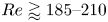 $Re \gtrapprox 185\unicode{x2013} 210$ (Jiang & Cheng Reference Jiang and Cheng2018). Hence, the results presented in this section for
  $Re > 160$ are only representative of the two-dimensional periodic base-flow and further three-dimensional simulations would be required to evaluate the effect of the flaps in the presence of spanwise flow variation.
3.4. Drag reduction scaling
Here, the scaling of the mean drag reduction for all flap lengths, forcing amplitudes and aspect ratios is presented. To begin with, each plate produces thrust which in turn results in a subsequent drag reduction for the bluff body. Since the thrust produced by each flap is proportional to the product of the tip velocity squared and the flap length (i.e.  $\overline {U^{2}_{tip}}l_{f}$) (Beal et al. Reference Beal, Hover, Triantafyllou, Liao and Lauder2006; Gazzola et al. Reference Gazzola, Argentina and Mahadevan2014; Floryan, Van Buren & Smits Reference Floryan, Van Buren and Smits2020) then it follows that the drag reduction should scale as
 \begin{equation} \overline{C_D}/\overline{C^{*}_{D_{0}}} \sim \overline{U^{2}_{tip}}l_{f}. \end{equation}
The tip-speed velocity of the flap is given by  $U_{tip} = \omega l_f$, where the angular velocity of the flap is
  $\omega = {\mathrm {d}\theta }/{\mathrm {d}t} = 2 {\rm \pi}St_f \theta _{o} \cos (2 {\rm \pi}St_f t)$. Hence, all the design parameters of the system (
 $\theta _{o}$,
  $l_f$,
  $f$) are present in the proposed scaling parameter. The overbar over the tip-speed and angular velocity represents mean quantities. Here, the normalisation of
  $\overline {C_D}/\overline {C^{*}_{D_{0}}}$ is used, where
  $\overline {C^{*}_{D_{0}}}$ corresponds to the mean coefficient of the unforced flow with an effective aspect ratio,
  $AR^{*} = AR+l_f$. This modified normalisation solely influences the level of the normalised mean drag and allows the collapse of data with different aspect ratios. It should be highlighted that while the normalisation of the drag with
  $\overline {C_{D_{0}}}$ could also be used, the collapse of the data shown in figure 16 would not be satisfactory with the data of each aspect ratio being shifted vertically. As it will be demonstrated in the subsequent paragraphs, the new scaling can be used to collapse the mean drag reduction outside of the resonant regions even when both the symmetrisation and propulsive mechanisms contribute to the obtained drag reduction.


Figure 16 shows the scaled behaviour of the FC and CC and snaking motions presented in figures 5 and 9. Further, the amplitude response data of figure 14 have also been included. The drag ratios collapse well over a large range of flap lengths  $l_f=0.4,0.6,0.8,1.0$, Strouhal numbers
  $0.025 \le St_f \le 0.40$ and aspect ratios
  $AR=1,2,4$ for both forcing motions and there is a linear relationship between the two parameters. This linearity can be seen more clearly in the corresponding figure in Appendix E. The resonant regions do not collapse due to the strong nonlinear effects, which are more pronounced for the snaking motion. Since the scaling is based on propulsion arguments, it cannot describe the nonlinear resonant interactions between the forcing and the vortex shedding. However, the resonant regions are always known (being near
  $St_0$ for snaking and
  $2 \times St_0$ for clapping).
3.5. Performance
Finally, an investigation on the performance of the clapping and snaking forcing strategies for various Strouhal numbers and flap lengths is presented. The performance is assessed by the effectiveness ratio  $E$ which is defined as the power ratio between drag power saved,
  $P_{save}$, and power input to the flaps,
  $P_{in}$:
 \begin{equation} E = \frac{P_{save}}{P_{in}} =\frac{ (\overline{ F_D} - \overline{ F_{D_{F}}} )U_\infty}{\overline{T \omega}}, \end{equation}
where  $F_{D_{F}}$ is the drag with fixed rear flaps at an angle
  $\theta _f = 0$ (see Appendix B) and
  $P_{in}= \overline {T \omega }$ is the time-averaged input power required to overcome the hydrodynamic forces acting on the flaps. Here,
  $T$ represents the torque and
  $\omega$ the rotational velocity of the flaps. The torque is calculated by the product of the normal forces acting on the flaps and the distance from the hinge to the centre of gravity which is the half-flap-length:
  $T = (F_D \sin (\theta ) + F_L \cos (\theta )) l_f/2$. Here,
  $\theta$ represents the instantaneous angle of each pitching flap (a detailed description of the definition of
  $\theta$ is presented in § 2.2). The input power does not account for any losses such as electromechanical ones related to flap actuation. The hydrodynamic forces acting on each flap are calculated via a momentum balance in a control volume surrounding only the individual flap of interest. Equation (3.2) is essentially the same as the propulsion efficiency commonly used for pitching foils (Buchholz & Smits Reference Buchholz and Smits2008; Taylor Reference Taylor2018; Wu et al. Reference Wu, Zhang, Tian, Li and Lu2020), which is defined as the ratio of the thrust to the input power. Here, instead of thrust we use the drag saving in the nominator of (3.2), which is commonly used for the quantification of performance of active flow control (Choi et al. Reference Choi, Jeon and Kim2008; Barros et al. Reference Barros, Jacques, Noack, Spohn and Ruiz2016b). The drag saving definition allows the comparison of the active control technique via rear pitching flaps and the passive technique of fixed rear flaps.
The effectiveness ratio can take any real value. When the forcing strategy results in a drag increase, the ratio becomes negative. Contrarily, when a drag reduction is achieved but more energy has to be spent compared with the power saving, the effectiveness takes values between zero and one. Finally, for effectiveness values greater than unity, the forcing strategy is beneficial and suggests that a net energy saving can potentially be achieved. Effectiveness values smaller than minus one indicate that an energy efficient deceleration (braking) can be achieved.
Figure 17 shows the effectiveness with the snaking and clapping forcing strategies with flap lengths of  $l_f=0.4,0.6$ and
  $AR=1$. The strong resonant interaction between the snaking motion and the vortex shedding results in extremely effective drag increase at
  $St_f \approx St_0$, which increases by increasing the length of the flap.
Effectiveness ratio for the snaking and clapping strategies with  $AR=1$ and
  $l_f=0.4$ (a) and
  $l_f=0.6$ (b) for a wide range of flapping Strouhal numbers. The two vertical dashed lines indicate the natural Strouhal numbers
  $St_0$ and
  $2 \times St_0$, whereas the solid horizontal ones correspond to a unity ratio.

The FC and snaking strategies show a potential for a net power saving only for a narrow range of forcing Strouhal numbers with  $l_f=0.6$. In fact, for the smallest flap length
  $l_f=0.4$ these strategies result in effectiveness values below unity for all
  $St_f$ considered. Contrarily, the CC emerges as the most efficient drag reduction strategy by consistently achieving a net energy saving for both flap lengths and for a wide range of Strouhal numbers. Similar to the propulsive performance of single pitching foils (Taylor Reference Taylor2018) the effectiveness shows the existence of an optimum Strouhal number. The optimal forcing frequency is
  $St_f\approx 0.3$ and
  $St_f\approx 0.2$ for the two flap lengths. The better performance of this strategy stems from the restricted flap motion that avoids the interaction with the high-speed shear layer regions.
4. Conclusion and outlook
A numerical study based on nearly 600 high-fidelity simulations on the response of a two-dimensional laminar bluff body wake subjected to harmonic forcing with two thin and pitching rear flaps has been presented in this paper. The effects of the flap length, flapping amplitude, flapping Strouhal number and aspect ratio have been examined along with the Reynolds number dependency for two different forcing strategies (snaking and clapping). The flow simulations have been performed with the high-order finite-difference solver Incompact3d which was combined with the ADR-IBM in order to simulate the moving flaps and the bluff body.
The snaking motion results in a strong fundamental resonance near the natural (unforced) Strouhal number of the base flow. This fundamental resonance is the result of the interaction between the primary vortex shedding mode and the forcing. This results in the amplification of the former and a significant increase in the r.m.s. of the drag coefficient and a trough in the lift r.m.s. Subsequently, a considerable increase in the mean drag occurs. No fundamental resonance has been observed for the clapping motion. Contrarily, a subharmonic resonance occurs at twice the natural frequency. This subharmonic resonance which also amplifies the primary vortex shedding mode results in a sharp increase in the lift r.m.s. and a subsequent increase in the mean drag (the drag r.m.s. remains unaffected). The clapping motion can produce significant drag reductions for nearly all Strouhal numbers, flap lengths and aspect ratios. With increased forcing (due to the flapping Strouhal number and/or flap length) the wake becomes symmetrised and the resonant effect diminishes. Once the wake has been fully symmetrised, the vortex shedding instability is suppressed and the subharmonic resonance can no longer occur.
Both forcing strategies are capable of producing considerable drag reductions through a wake symmetrisation and propulsive mechanisms. An important aspect of the wake symmetrisation mechanism for both motions is the formation and ejection of a VD which weakens the primary vortex that gives rise to the vortex shedding.
Further, a scaling parameter based on the propulsive regime has been proposed. The scaling requires solely two parameters (the flap length and the flap tip velocity), which are known a priori. A very good collapse of the drag ratio is obtained for all aspect ratios, flap lengths, flapping Strouhal numbers and pitching amplitudes for both the snaking and clapping forcing strategies. Finally, an effectiveness ratio is proposed to assess the performance of each forcing strategy and indicate whether a net energy saving is possible. The FC and snaking strategies are ineffective for the smallest flap length  $l_f=0.4$ and only show potential for a very narrow range of Strouhal numbers for the larger flap length
  $l_f=0.6$. Contrarily, the CC motion appears to be the most reliable for the parameter ranges considered in this study.
The next step is to extend this work to higher Reynolds numbers with three-dimensional LES in order to study the effect of the spanwise aspect ratio of the body and assess the validity of the proposed scaling. Further, it will be sought to improve the performance of the technology further by adding flexibility to the flaps and by adding fluid–structure interaction capability to Incompact3d. Since flexible pitching flaps have better propulsive performance compared with rigid ones (Michelin, Llewellyn & Stefan Reference Michelin, Llewellyn and Stefan2009; Wang, Huang & Lu Reference Wang, Huang and Lu2021), they could be highly beneficial for the configuration studied in this paper.
Acknowledgments
The authors thank EPSRC for the computational time made available on the UK supercomputing facility ARCHER via the UK Turbulence Consortium (EP/R029326/1).
Funding
The authors would like to acknowledge the Department of Aeronautics at Imperial College London for supporting this work with a fully funded PhD studentship.
Declaration of interests
The authors report no conflict of interest.
Appendix A. Canonical manoeuvre
To further demonstrate the ability and robustness of the ADR-IBM to handle simulations of thin moving boundaries, the test case of the large amplitude pitch-up, hold, pitch-down manoeuvre which was introduced by Eldredge, Wang & Ol (Reference Eldredge, Wang and Ol2009) is considered. The manoeuvre which was designed to study separation phenomena in pitching airfoils is characterised by the angle of attack (AoA) of the flat plate  $\alpha (t)$:
 \begin{align} \alpha(t) = \alpha_0 + \alpha_{max} \frac{G(t)}{\max(G(t))}, \quad G(t) = \log \left[ \frac{\cosh(a(t-t_1)) \cosh(a(t-t_4))}{\cosh(a(t-t_2)) \cosh(a(t-t_3))} \right], \end{align}
where the plate starts with an initial AoA  $\alpha _0 = 15 ^{\circ }$ and reaches a maximum angle of
  $25 ^{\circ }$ (with the pitching amplitude being
  $\alpha _{max}=10 ^{\circ }$). The plate pitches about its leading edge and the parameter
  $a=11$ determines the smoothness of corners of the manoeuvre and
  $t_1 = 1$,
  $t_2 = 3$,
  $t_3 = 4$,
  $t_4 = 6$.
The Reynolds number which is based on the chord length ( $c=1$) of the flat plate with
  $1\,\%$ thickness is set at
  $Re=100$, and a rectangular domain
  $L_x \times L_y = 10c \times 6c$ is considered with a resolution of
  $n_x \times n_y = 1025 \times 768$. A stretched mesh is used in the vertical direction towards the centre of the domain with a minimum mesh spacing
  $\Delta _y = 0.0065c$ and a time step of
  $\Delta t = 5 \times 10^{-5} c/u_{\infty }$ is selected.
Figure 18 shows the time evolution of the AoA (see (A1a,b)) of the flat plate and compares the lift coefficient obtained with the ADR-IBM with the DNS results of Brunton & Rowley (Reference Brunton and Rowley2011) and Brunton, Rowley & Williams (Reference Brunton, Rowley and Williams2013). The lift coefficient appears to be in excellent agreement with both DNS studies.
The AoA (a) and lift coefficient  $C_L$ (b) against convective time for the flow over a flat plate undergoing a canonical manoeuvre at
  $Re=100$.

Appendix B. Fixed flaps
As it has been reported in the literature (Lanser et al. Reference Lanser, Ross and Kaufman1991; Khalighi et al. Reference Khalighi, Zhang, Koromilas, Balkanyi, Bernal, Iaccarino and Moin2001; Storms et al. Reference Storms, Satran, Heineck and Walker2004; Browand et al. Reference Browand, Radovich and Boivin2005), the addition of fixed flaps at the rear base of a bluff body (commonly known as boat-tailing devices) can reduce the aerodynamic drag by altering the wake and increasing the base pressure. In this section, a brief study on the drag reduction effects of two fixed flaps at the rear of a rectangular bluff body ( $AR=1$) are presented for zero yaw angle at
  $Re=100$. The effects of various fixed flap angles (
 $0^{\circ } \le \theta _{f} \le 20^{\circ }$) for various lengths
  $l_{f} = 0.2, 0.4, 0.6, 0.8, 1.0$ are examined.
Figure 19 shows the evolution of the drag ratio for various flap angles. Overall, this passive device is highly beneficial as it results in considerable drag reductions for all the parameters studied here. The drag ratio variations which are very small for  $l_f=0.2$ become more significant as the flap length is increased. An optimum angle
  $7.5 ^{\circ } \lessapprox \theta _{opt} \lessapprox 10 ^{\circ }$ exists for each length. At this point it should be stressed that even though significant drag reductions can be obtained with this passive device (as demonstrated here for a zero yaw angle), unpredictable real life operating conditions could easily result in suboptimal situations. Hence, only a closed-loop control strategy could ensure the optimum performance of the design and extend its operational range.
Normalised drag coefficients for the flow over a rectangular bluff body with aspect ratios  $AR=1$ with fixed rear flaps of varying length and flap angles. The solid horizontal line corresponds to a unity ratio.

Appendix C. Wake symmetrisation
Here the method which allows the determination of the wake symmetrisation extent is presented. When the flow has been fully symmetrised, the vertical component of the velocity  $v$ at the body's centreline is zero. Hence, the assessment of the extent of the wake's symmetrisation can be determined based on the values of
  $v$ downstream of the body which are a proxy for the unsteady global vortex shedding amplitude. A small threshold (
 $|v| \le 0.07$) is selected, below which the wake is considered symmetrised. Figure 20 shows the evolution of
  $v$ in the streamwise direction and corresponds to the vorticity contours shown in figure 7 at
  $t=T$. As can be seen, the wake is symmetrised between
  ${\sim }6H_C\unicode{x2013} 13H_C$ downstream of the body's rear. The large velocity amplitudes which are observed near the body's rear surface (
 $4.0 \le x \le 6.0$) are a result of the formation of the strong VD.
Evolution of the vertical velocity component along the streamwise direction at the centreline of the bluff body with the in-phase snaking motion ( $AR=4$,
  $Re=100$,
  $l_{f}=1.0$,
  $St_f=0.40$) corresponding to the instantaneous vorticity contours shown in figure 7. The vertical dashed line marks the location of the body's rear. The two horizontal dashed lines indicate the symmetrisation threshold.

Similarly, figure 21 shows that for the out-of-phase FC motion ( $AR=4$,
  $Re=100$,
  $l_{f}=0.6$), the wake is symmetrised for
  ${\sim }8.75H_C, 13.0H_C, 7.0H_C$ for
  $St_f=0.10, 0.20, 0.24$, respectively. While the symmetrisation extent is increased between
  $St_f=0.10$ and
  $St_f=0.20$, a considerable reduction is observed at
  $St_f=0.24$. This disruption of the gradual wake symmetrisation is due to the subharmonic resonance which occurs at
  $St_f=0.24$. At
  $St_f=0.40$ the wake has been fully symmetrised.
Evolution of the vertical velocity component along the streamwise direction at the centreline of the bluff body with the out-of-phase FC motion ( $AR=4$,
  $Re=100$,
  $l_{f}=0.6$,
  $St_f=0.10, 0.20, 0.24, 0.40$) corresponding to the instantaneous vorticity contours shown in figure 11. The vertical dashed line marks the location of the body's rear. The two horizontal dashed lines indicate the symmetrisation threshold.

Appendix D. Pressure contours
Here instantaneous pressure contours are presented for the in-phase and out-of-phase motions. Figure 22 shows the pressure fields obtained with the snaking motion ( $AR=1$,
  $Re=100$,
  $l_{f}=1.0$) for various Strouhal numbers (see figure 6 for the corresponding vorticity contours). At
  $St_f=0.165$, a large pressure drop can be observed at the body's rear surface (compared with other forcing Strouhal numbers) due to the fundamental resonance which amplifies the vortex shedding and leads to the generation of very strong vortices.
Instantaneous pressure fields at  $t=5T/8$ with the in-phase snaking motion for a range of flapping frequencies (
 $AR=1$,
  $Re=100$,
  $l_{f}=1.0$).

Figure 23 shows the pressure fields obtained with the FC motion ( $AR=1$,
  $Re=100$,
  $l_{f}=0.6$) for various Strouhal numbers (see figure 10 for the corresponding vorticity contours). Due to the symmetry of the forcing, the shed vortices are not strong enough to generate a pressure drop on the body's rear surface. Instead, the pressure shows a small increase as the two flaps reduce the size of the rear cavity due to their motion.
Instantaneous pressure fields at  $t=T/2$ with the out-of-phase FC motion for a range of flapping frequencies (
 $AR=1$,
  $Re=100$,
  $l_{f}=0.6$).

Appendix E. Drag reduction scaling
Figure 24 shows the normalised drag coefficient  $\overline {C_D}/\overline {C^{*}_{D_{0}}}$ plotted against the scaling parameter
  $\overline {U^{2}_{tip}}l_{f}$ for three aspect ratios (
 $AR=1,2,4$) and various flap lengths (
 $l_f = 0.4,0.6,0.8,1.0$) with the out-of-phase FC motion (for the data presented in figure 9). As it can be seen, there is a linear relationship between the two parameters and the data collapse well for each aspect ratio.
Scaled behaviour of the mean normalised drag  $\overline {C_D}/\overline {C^{*}_{D_{0}}}$ with
  $AR=1$ (a),
  $AR=2$ (b) and
  $AR=4$ (c) for the out-of-phase FC motion for the data presented in figure 9.


 Open access