


1. Introduction
It has long been known that rotating spherical shell convection significantly differs between the low latitudes (e.g. Busse & Cuong Reference Busse and Cuong1977; Gillet & Jones Reference Gillet and Jones2006) situated outside the axially aligned cylinder that circumscribes the inner spherical shell boundary (the tangent cylinder, TC) and the higher latitude polar regions lying within the TC (e.g. Aurnou et al. Reference Aurnou, Andreadis, Zhu and Olson2003; Sreenivasan & Jones Reference Sreenivasan and Jones2006; Aujogue et al. Reference Aujogue, Pothérat, Sreenivasan and Debray2018; Cao, Yadav & Aurnou Reference Cao, Yadav and Aurnou2018). Further, in the atmosphere–ocean literature, latitudinal separation into polar, mid-latitude, extra-tropical and tropical zones is essential to accurately model the large-scale dynamics (e.g. Vallis Reference Vallis2017). Yet few scaling studies of spherical shell convection consider the innate regionalization of the dynamics (cf. Wang et al. Reference Wang, Santelli, Lohse, Verzicco and Stevens2021), and instead mostly focus on globally averaged quantities (e.g. Gastine, Wicht & Aubert Reference Gastine, Wicht and Aubert2016; Long et al. Reference Long, Mound, Davies and Tobias2020).
In the turbulent rapidly rotating limit, theory requires the convective heat transport to be independent of the fluid diffusivities irregardless of system geometry. This yields (e.g. Julien et al. Reference Julien, Rubio, Grooms and Knobloch2012b; Plumley & Julien Reference Plumley and Julien2019)
 \begin{equation} Nu \sim (Ra/Ra_c)^{3/2} \sim \widetilde{Ra}^{3/2}Pr^{{-}1/2} \sim Ra^{3/2} E^{2} Pr^{{-}1/2}, \end{equation}
where, defined explicitly below, the Nusselt number  $Nu$ is the non-dimensional heat transfer, $Ra$ ( $Ra_c$) denotes the (critical) Rayleigh number, $E$ is the Ekman number, $Pr$ is the Prandtl number, and $\widetilde {Ra} \equiv Ra\,E^{4/3}$ expresses the generalized convective supercriticality (Julien et al. Reference Julien, Rubio, Grooms and Knobloch2012b).
Cylindrical laboratory experiments with  $Pr\approx 7$ and Cartesian (planar) numerical simulations with $Pr=(1, 7)$ and no-slip boundaries with $Ra/Ra_c \lesssim 10$ reveal a steep scaling $Nu \sim (Ra/Ra_c)^\beta$ with $\beta \approx 3$ (King, Stellmach & Aurnou Reference King, Stellmach and Aurnou2012; Cheng et al. Reference Cheng, Stellmach, Ribeiro, Grannan, King and Aurnou2015, Reference Cheng, Aurnou, Julien and Kunnen2018). By comparing numerical models with stress-free and no-slip boundaries, Stellmach et al. (Reference Stellmach, Lischper, Julien, Vasil, Cheng, Ribeiro, King and Aurnou2014) showed that the steep $\beta \approx 3$ scaling is an Ekman pumping effect (cf. Julien et al. Reference Julien, Aurnou, Calkins, Knobloch, Marti, Stellmach and Vasil2016). For larger supercriticalities, $\beta$ decreases and gradually approaches (1.1). This $\beta \approx 3$ regime is expected to hold as long as the thermal boundary layers are in quasi-geostrophic balance, a condition approximated by $Ra\,E^{8/5} \lesssim 1$ (Julien et al. Reference Julien, Knobloch, Rubio and Vasil2012a).
Globally averaged quantities in spherical shell models present several differences with the planar configuration. In particular, no steep  $\beta \approx 3$ exponent is observed. Gastine et al. (Reference Gastine, Wicht and Aubert2016) showed that the globally averaged heat transfer first follows a $Nu-1 \sim Ra/Ra_c -1$ weakly nonlinear scaling for $Ra \leq 6\,Ra_c$ before transitioning to a scaling close to (1.1) for $Ra > 6\,Ra_c$ and $Ra E^{8/5} < 0.4$. Spherical shell models with a ratio between the inner radius $r_i$ and the outer radius $r_o$ of $0.35$ and fixed-flux thermal conditions recover similar global scaling behaviours, though with a slightly larger exponent $\beta \approx 1.75$ for $E=2\times 10^{-6}$ (Long et al. Reference Long, Mound, Davies and Tobias2020). Because the Ekman pumping enhancement of heat transfer is maximized when rotation and gravity are aligned, $\beta$ is lower in the equatorial regions of spherical shells. This explains why globally averaged spherical $\beta$ values cannot attain the $\beta \approx 3$ values found in planar (polar-like) studies.
Recently, Wang et al. (Reference Wang, Santelli, Lohse, Verzicco and Stevens2021) analysed heat transfer within the equatorial regions, at mid-latitudes and inside the entire TC. They argued that the mid-latitude scaling in their models, similar to Gastine et al. (Reference Gastine, Wicht and Aubert2016)'s global scaling, follows the diffusion-free scaling (1.1), while the region inside the TC follows a  $\beta \approx 2.1$ trend. This TC-scaling exponent is significantly smaller than those obtained in planar models, possibly because of the finite inclination angle between gravity and the rotation axis averaged over the volume of the TC.
Following Wang et al. (Reference Wang, Santelli, Lohse, Verzicco and Stevens2021), this study aims to better characterize the latitudinal variations in rotating convection dynamics and quantify the differences between spherical and non-spherical geometries. To do so, we carry out local heat transfer analyses in the polar and equatorial regions over an ensemble of  $Pr=1$ rotating spherical shell simulations with $r_i/r_o=0.35$ and $r_i/r_o=0.6$.
2. Hydrodynamical model
We consider a volume of fluid bounded by two spherical surfaces of inner radius  $r_i$ and outer radius $r_o$ rotating about the $z$-axis with a constant rotation rate $\varOmega$. Both boundaries are mechanically no-slip and are held at constant temperatures $T_o=T(r_o)$ and $T_i=T(r_i)$. We adopt a dimensionless formulation of the Navier–Stokes equations using the shell gap $d=r_o-r_i$ as the reference length scale, the temperature contrast $\Delta T=T_o-T_i$ as the temperature unit, and the inverse of the rotation rate $\varOmega ^{-1}$ as the time scale. Under the Boussineq approximation, this yields the following set of dimensionless equations for the velocity $\vec {u}$ and temperature $T$ expressed in spherical coordinates:
 $$\begin{gather} \dfrac{\partial \vec{u}}{\partial t}+\vec{u}\boldsymbol{\cdot}\vec{\nabla}\vec{u}+2\vec{e_z}\times\vec{u}={-}\vec{\nabla}p + \dfrac{Ra E^2}{Pr} T\,g(r)\vec{e_r}+ E\,{\nabla}^2\vec{u}, \quad\vec{\nabla}\boldsymbol{\cdot}\vec{u}=0, \end{gather}$$
 $$\begin{gather}\dfrac{\partial T}{\partial t}+\vec{u}\boldsymbol{\cdot}\vec{\nabla}T = \dfrac{E}{Pr}{\nabla}^2 T, \end{gather}$$
where  $p$ corresponds to the non-hydrostatic pressure, $g$ to gravity and $\vec {e_r}$ ( $\vec {e_z}$) denotes the unit vector in the radial (axial) direction. The above equations are governed by the dimensionless Rayleigh, Ekman and Prandtl numbers, respectively defined by
 \begin{equation} Ra=\dfrac{\alpha g_o \Delta T d^3}{\nu \kappa},\quad E=\dfrac{\nu}{\varOmega d^2},\quad Pr = \dfrac{\nu}{\kappa}, \end{equation}
where  $\nu$ and $\kappa$ correspond to the constant kinematic viscosity and thermal diffusivity, $g_o$ is the gravity at the external radius and $\alpha$ is the thermal expansion coefficient. Two spherical shell configurations are employed: (i) a thin shell with $r_i/r_o=0.6$ under the assumption of a centrally condensed mass with $g=(r_o/r)^2$ (Gilman & Glatzmaier Reference Gilman and Glatzmaier1981); (ii) a self-gravitating thicker spherical shell model with $r_i/r_o=0.35$ and $g=r/r_o$. The latter corresponds to the standard configuration employed in numerical models of Earth's dynamo (e.g. Christensen & Aubert Reference Christensen and Aubert2006; Schwaiger, Gastine & Aubert Reference Schwaiger, Gastine and Aubert2019). We consider numerical simulations with $10^4 \leq Ra \leq 10^{11}$, $10^{-7} \leq E \leq 10^{-2}$ and $Pr=1$ computed with the open source code MagIC (https://github.com/magic-sph/magic.) (Wicht Reference Wicht2002; Gastine & Wicht Reference Gastine and Wicht2012). We mostly build the current study on existing numerical simulations from Gastine et al. (Reference Gastine, Wicht and Aubert2016) and Schwaiger, Gastine & Aubert (Reference Schwaiger, Gastine and Aubert2021) and continue their time integration to gather additional diagnostics when required.
In the following analyses overbars denote time averages, triangular brackets denote azimuthal averages and square brackets denote averages about the angular sectors comprised between the colatitudes  $\theta _0-\alpha$ and $\theta _0+\alpha$ in radians:
 \begin{align} \bar{f} = \int_{t_0}^{t_0+\tau}f\,\mathrm{d}t,\quad \langle\, f \rangle = \dfrac{1}{2{\rm \pi}}\int_{0}^{2{\rm \pi}} f(r,\theta,\phi,t)\,\mathrm{d}\phi, \quad \left[ f \right]_{\theta_0}^{\alpha} =\dfrac{1}{\mathcal{S}_{\theta_0}^\alpha}\int_{\mathcal{S}_{\theta_0}^\alpha} f(r,\theta,\phi,t)\,\mathrm{d}\mathcal{S}, \end{align}
with  $\mathrm {d}\mathcal {S} = \sin \theta \,\mathrm {d}\theta$ and $\mathcal {S}_{\theta _0}^\alpha =\int _{\min (\theta _0-\alpha,0)}^{ \max (\theta _0+\alpha,{\rm \pi} ) } \sin \theta \,\mathrm {d}\theta$.
For the sake of clarity, we introduce the following notations to characterize the time-averaged radial distribution of temperature:
 \begin{equation} \vartheta(r)=[\langle \bar{T} \rangle ]_{{\rm \pi}/2}^{{\rm \pi}/2}, \quad \vartheta_e(r)= [\langle \bar{T} \rangle ]_{{\rm \pi}/2}^{{\rm \pi}/36}, \quad \vartheta_p(r)=\frac{1}{2}\left([\langle \bar{T} \rangle ]_{0}^{{\rm \pi}/36}+[\langle \bar{T} \rangle ]_{\rm \pi}^{{\rm \pi}/36}\right), \end{equation}
where  $\vartheta _e$ and $\vartheta _p$ correspond to the averaged radial distribution of temperature in the equatorial and polar regions, respectively, and $\alpha = {\rm \pi}/36$ rad corresponds to $5^\circ$ in colatitudinal angle. The schematic shown in figure 1(a) highlights the fluid volumes involved in these measures. The value of $\alpha =5^\circ$ is quite arbitrary and has been adopted to allow a comparison of polar data with local planar Rayleigh–Bénard convection (hereafter RBC) models while keeping a sufficient sampling.
(a) Schematic showing the area selection to compute (2.7a,b), the local polar (blue) and equatorial (red) Nusselt numbers. (b) Time-averaged local Nusselt numbers in the polar ( $Nu_p$) and equatorial ( $Nu_e$) regions as a function of the Rayleigh number for spherical shell simulations with $r_i/r_o=0.6$ and $g=(r_o/r)^2$ and $Pr=1$ (Gastine et al. Reference Gastine, Wicht and Aubert2016). The different Ekman numbers are denoted by different symbol shapes, the two spherical shells surfaces $r_i$ and $r_o$ are marked by open and filled symbols, and by lower levels of opacity, respectively.

To quantify the differences between the heat transfer in the polar and equatorial regions, we introduce a Nusselt number that depends on colatitude  $\theta$ via
 \begin{equation} Nu_i(\theta) = \dfrac{\left.\dfrac{\mathrm{d} \langle \bar{T} \rangle }{\mathrm{d}{r}}\right|_{r_i}}{ \left.\dfrac{\mathrm{d} T_c}{\mathrm{d}{r}}\right|_{r_i}}, \quad Nu_o(\theta) = \dfrac{\left.\dfrac{\mathrm{d} \langle \bar{T} \rangle }{\mathrm{d}{r}}\right|_{r_o}}{ \left.\dfrac{\mathrm{d} T_c}{\mathrm{d}{r}}\right|_{r_o}}, \quad \dfrac{\mathrm{d} T_c}{\mathrm{d} r} ={-}\dfrac{r_i r_o}{r^2}, \end{equation}
where  $T_c$ corresponds to the dimensionless temperature of the conducting state. The corresponding local Nusselt numbers in the equatorial and polar regions are then defined by
 \begin{equation} Nu_e=[Nu(\theta)]_{{\rm \pi}/2}^{{\rm \pi}/36}, \quad Nu_p=\frac{1}{2}\left([\langle Nu(\theta) \rangle ]_{0}^{{\rm \pi}/36}+[\langle Nu(\theta) \rangle ]_{\rm \pi}^{{\rm \pi}/36}\right). \end{equation}
We finally introduce the mid-shell time-averaged temperature gradient in the polar region:
 \begin{equation} \partial T = \dfrac{ -\left.\dfrac{\mathrm{d}\vartheta_p}{ \mathrm {d} r}\right|_{r=r_m}}{ -\left. \dfrac{\mathrm{d}T_c}{ \mathrm {d} r}\right|_{r=r_m} }, \quad r_m=\dfrac{1}{2}(r_i+r_o), \end{equation}
where normalization by the conductive temperature gradient allows us to compare the scaling behaviour of  $\partial T$ between spherical shells of different radius ratio values, $r_i/r_o$, and planar models.
3. Results
Figure 1(b) shows  $Nu_p$ and $Nu_e$ as a function of $Ra$ for various $E$ at both boundaries, $r_i$ and $r_o$, for spherical shell simulations with $r_i/r_o=0.6$ and $g=(r_o/r)^2$. Rotation delays the onset of convection such that the critical Rayleigh number required to trigger convective motions increases with decreasing Ekman number, $Ra_c \sim E^{-4/3}$. Convection first sets in outside the TC (e.g. Dormy et al. Reference Dormy, Soward, Jones, Jault and Cardin2004). For each Ekman number, heat transfer behaviour in the equatorial regions (red symbols) first raises slowly following a weakly nonlinear scaling (e.g. Gillet & Jones Reference Gillet and Jones2006), before gradually rising in the vicinity of $Nu_e \approx 2$. At $Nu_e \gtrsim 2$, the heat transfer increases more steeply with $Ra$, before gradually tapering off toward the non-rotating RBC trend (e.g. Gastine, Wicht & Aurnou Reference Gastine, Wicht and Aurnou2015). For $Ra/Ra_c > {O}(10)$, convection sets in in the polar regions and $Nu_p$ steeply rises with $Ra$ with a much larger exponent than $Nu_e$. At still larger forcings, the slope of $Nu_p$ gradually decreases and comparable amplitudes in polar and equatorial heat transfers are observed. Heat-transfer scalings at both spherical shell boundaries $r_i$ and $r_o$ follow similar trends.
Figure 2 shows (a)  $Nu_p$ and $Nu_e$ and (b) their ratio $Nu_p/Nu_e$ plotted at both boundaries as a function of the supercriticality parameter $\widetilde {Ra} = Ra E^{4/3}$. For $\widetilde {Ra} < 4$, $Nu_e$ increases following the weakly nonlinear form $Nu_e-1\sim Ra/Ra_c-1$ (Gastine et al. Reference Gastine, Wicht and Aubert2016, § 3.1). For larger supercriticalities, the $Nu_e$ scaling steepens and an additional $E$-dependence causes the data to fan out, possibly because these highest $\widetilde {Ra}$ cases do not fulfil $Ra\,E^{8/5}<0.4$. There is no clear power-law scaling in the $Nu_e (\widetilde {Ra} < 10)$ data, but the steepest local slope yields $\max (\beta ) \approx 1.9$ in the $5 \leq \widetilde {Ra} \leq 10$ range.
(a) Nusselt number in the polar ( $Nu_p$) and in the equatorial ( $Nu_e$) regions as a function of $\widetilde {Ra}=Ra\,E^{4/3}$ in the $r_i/r_o = 0.6$ simulations. The symbols carry the same meaning as in figure 1 but with only the $Ra\,E^{8/5} < 2$ simulations retained. (b) Ratio of polar and equatorial heat transfer $Nu_p/Nu_e$ as a function of $\widetilde {Ra}$ for both spherical shell boundaries and $E \leq 10^{-4}$.

Best fits to the figure 2(a) data show that polar convection onsets at  $\widetilde {Ra} (E) = 11.2 \pm 0.3$ in the $r_i/r_o = 0.6$ simulations. The mean value of the critical polar Rayleigh number is
 \begin{equation} Ra_c^p = 11.2\,E^{{-}4/3}. \end{equation}
Although the polar onset of convection, estimated via  $Ra_c^p \, E^{4/3}$, remains nearly constant, the global (e.g. low latitude) onset value, estimated by $Ra_c \, E^{4/3}$, varies by a factor of ${\approx }2$ over our $E$ range. Their ratio then yields
 \begin{equation} Ra_c^p (E)/Ra_c(E) = 20 \pm 5. \end{equation}
This means that rotating convection does not typically onset in the polar regions until the lower latitude convection is already 20 times supercritical and is already operating under highly supercritical conditions. This difference in equator vs polar convective onsets imparts a significant regionalization to rotating spherical shell convection right from the get go.
We find, throughout this investigation, that polar rotating convection compares closely to its plane-layer counterpart. However, it is not expected that the polar critical Rayleigh number will exactly agree with plane-layer predictions, due to the effects of finite spherical curvature as well as the radial variations of gravity in these  $r_i/r_o = 0.6$ simulations. In the rapidly rotating thin-shell limit, in which $r_i/r_o \rightarrow 1$ and $E$ is kept asymptotically small, $Ra_c^p$ will likely approach the planar value. Still, the polar scaling in (3.1) is found to be 51 % of the plane-layer $E \rightarrow 0$ scaling prediction, $Ra_c = 21.9\,E^{-4/3}$ (Kunnen Reference Kunnen2021), and to be 56 % of Niiler & Bisshopp (Reference Niiler and Bisshopp1965)'s finite Ekman number, no-slip plane layer $Ra_c$ prediction at $E = 10^{-6}$. In addition to the similarity in critical $Ra$ values, it is found that the polar heat transfer $Nu_p$ rises sharply once polar convection onsets, following a $Nu_p \sim \widetilde {Ra}^3$ scaling that matches the heat-transfer scalings found in no-slip planar simulations carried out over the same $(E, Pr)$ ranges (King et al. Reference King, Stellmach and Aurnou2012; Stellmach et al. Reference Stellmach, Lischper, Julien, Vasil, Cheng, Ribeiro, King and Aurnou2014; Aurnou et al. Reference Aurnou, Calkins, Cheng, Julien, King, Nieves, Soderlund and Stellmach2015).
Figure 2(b) shows the ratio of polar to equatorial heat transport, which follows a distinct V-shape trend that can be decomposed in three regions: (i) for  $\widetilde {Ra}< 11.2$, $Nu_p\approx 1$ and the ratio depends directly on $Nu_e=f(\widetilde {Ra})$; (ii) for $11.2 < \widetilde {Ra} \lesssim 30$, $Nu_p$ raises much faster than $Nu_e$ hence increasing $Nu_p/Nu_e$; (iii) when rotational effects become less influential, $Nu_p/Nu_e \approx 1$ at $r_i$ and $Nu_p/Nu_e\approx 1.5$ at $r_o$.
Figure 3(a,b) shows the time-averaged temperature profiles in the polar and equatorial regions ( $\vartheta _p$ dashed lines and $\vartheta _e$ dot-dashed lines) alongside the volume-averaged temperature ( $\vartheta$, solid line) for two numerical models with $r_i/r_o=0.6$, $g=(r_o/r)^2$, $E=10^{-6}$ and different $Ra$. For the case with $Ra\approx 14.1\,Ra_c$ (figure 3a), low-latitude convection is active but has yet to start within the TC. The mean temperature in the polar regions $\vartheta _p$ thus closely follows the conductive profile $T_c$ (dotted line), while in the equatorial region we observe the formation of a thin thermal boundary layer at $r_i$ and a decrease of the temperature gradient in the fluid bulk. At larger convective forcing ( $Ra\approx 69.3\,Ra_c$, figure 3b), convection is space-filling. The temperature profiles in the polar and equatorial regions become comparable and a larger fraction of the temperature contrast is accommodated in the thermal boundary layers.
(a,b) Radial profiles of time-averaged temperature in the polar regions (blue dashed line), in the equatorial region (red dot-dashed line) and averaged of the entire spherical surface (tan solid line). For comparison, the conducting temperature profile  $T_c$ is also plotted as a black dotted line. Panel (a) corresponds to $r_i/r_o=0.6$, $g=(r_o/r)^2$, $E=10^{-6}$, $Ra=6.5\times 10^8$, $Pr=1$, while (b) corresponds to $r_i/r_o=0.6$, $g=(r_o/r)^2$, $E=10^{-6}$, $Ra=3.2\times 10^9$ and $Pr=1$. (c) Time-averaged local Nusselt number at both spherical shell boundaries as a function of the colatitude for simulations with $r_i/r_o=0.6$, $g=(r_o/r)^2$, $E=10^{-6}$, $Pr=1$ and increasing supercriticalities. Solid (dashed) lines correspond to $r_i$ ( $r_o$). The vertical solid lines mark the location of the TC. In all panels, the shaded regions correspond to one standard deviation about the time averages.

Figure 3(c) shows the latitudinal variations of the heat flux at both spherical shell boundaries for increasing supercriticalities. These profiles confirm that convection first sets in outside the TC while the high-latitude regions remain close to the conductive  $Nu = 1$ state up to $Ra_c^p$, and that the $Ra > Ra_c^p$ polar transfer rises quickly, thus reducing the latitudinal $Nu$ contrast. Both spherical-shell boundaries feature similar global trends, with interesting regionalized differences. The TC (solid vertical lines) is visible, for instance, in the outer-boundary heat transfer $Nu_o(\theta )$, manifesting itself in local maxima that persist between $15\,Ra_c$ and $70\, Ra_c$.
Figure 4 shows (a)  $Nu_p$ and (b) normalized mid-depth polar temperature gradients $\partial T$ as a function of $Ra/Ra_c^p$ for spherical-shell simulations with $r_i/r_o=0.6$ and $r_i/r_o=0.35$, and for Cartesian asymptotically reduced models (e.g. Plumley et al. Reference Plumley, Julien, Marti and Stellmach2016) and $E\geq 2\times 10^{-7}$, $Pr=1$ direct numerical simulations (Stellmach et al. Reference Stellmach, Lischper, Julien, Vasil, Cheng, Ribeiro, King and Aurnou2014). In this figure, $Ra_c^p$ is used for the critical $Ra$ values for spherical-shell data, whereas standard planar $Ra_c$ values are used for the plane-layer data. Good quantitative agreement is found in the $Nu_p$ and $\partial T$ data from spherical shell and planar models, with all the data sets effectively overlying one another. The $1 \lesssim Ra/Ra_c^p \lesssim 3$ heat transfer follows a $Nu_p \sim (Ra/Ra_c)^3$ scaling in all the data sets. At larger supercriticalities, the scaling exponent of $Nu_p$ decreases and the asymptotic $\beta = 3/2$ scaling appears to be approached in the highest supercriticality planar cases. The mid-depth temperature gradients quantitatively agree in all models as well, attaining a relatively large minimum value, $\partial T \approx 0.5$ near $Ra \approx 3\,Ra_c^p$, before increasing slightly in the highest supercriticality planar models.
(a) Nusselt number in the polar regions  $Nu_p$ as a function of the local supercriticality $Ra/Ra_c^p$. (b) Normalized mid-depth temperature gradient (2.8a,b) in the polar regions $\partial T$ as a function of the local supercriticality. Spherical-shell simulations include two configurations with $r_i/r_o=0.6$ and $g=(r_o/r)^2$ (light blue symbols, from Gastine et al. Reference Gastine, Wicht and Aubert2016) and $r_i/r_o=0.35$ and $g=r/r_o$ (dark blue symbols, from Schwaiger et al. Reference Schwaiger, Gastine and Aubert2021). All the simulations with $E \leq 10^{-5}$ and $Nu_p > 1$ have been retained. Direct numerical simulations (DNS) in Cartesian geometry with periodic horizontal boundary conditions (light yellow symbols) come from Stellmach et al. (Reference Stellmach, Lischper, Julien, Vasil, Cheng, Ribeiro, King and Aurnou2014), while non-hydrostatic quasi-geostrophic models (CNH-QGM) (red symbols) come from Plumley et al. (Reference Plumley, Julien, Marti and Stellmach2016).

4. Discussion
Globally averaged heat-transfer scalings for rotating convection differ between spherical and planar geometries with the latter yielding steeper  $Nu$-
$Nu$- $Ra$ scaling trends. By introducing regionalized measures of heat transfer, we have shown that this steep scaling can also be recovered in the polar regions of spherical shells. The comparisons in figure 4 reveal an almost perfect overlap in heat-transfer data between the two geometries. Importantly, this demonstrates that local, non-spherical models can be used to understand spherical systems (e.g. Julien et al. Reference Julien, Rubio, Grooms and Knobloch2012b; Horn & Shishkina Reference Horn and Shishkina2015; Cabanes et al. Reference Cabanes, Aurnou, Favier and Le Bars2017; Calkins Reference Calkins2018; Cheng et al. Reference Cheng, Aurnou, Julien and Kunnen2018; Miquel et al. Reference Miquel, Xie, Featherstone, Julien and Knobloch2018; Gastine Reference Gastine2019).
Our regional analysis shows that the use of global volume-averaged properties to interpret rotating spherical shell convection can be misleading since such averages are often made over regions with significantly differing convection dynamics (e.g. Ecke & Niemela Reference Ecke and Niemela2014; Lu et al. Reference Lu, Ding, Shi, Xia and Zhong2021; Grannan et al. Reference Grannan, Cheng, Aggarwal, Hawkins, Xu, Horn, Sánchez-Álvarez and Aurnou2022, in rotating cylinders). As such, it is quite likely that globally averaged  $\beta$ depends on the spherical shell radius ratio, $r_i/r_o$. In higher $r_i/r_o$ shells, more of the fluid will lie within the TC and the globally averaged $\beta$ will tend towards a polar value near $3$. In contrast, lower $r_i/r_o$ shells should trend towards regional $\beta$ values below $2$, as found in our $Nu_e$ data. We hypothesize further that the mid-latitude $\beta \simeq 3/2$ scaling in (Wang et al. Reference Wang, Santelli, Lohse, Verzicco and Stevens2021) may represent a combination of the low- and high-latitude scalings, which could also be tested by varying $r_i/r_o$.
A similar argument may also explain Wang et al. (Reference Wang, Santelli, Lohse, Verzicco and Stevens2021)'s higher latitude, TC heat-transfer scaling of  $\beta = 2.1$. We postulate that measuring the rotating heat transfer away from the poles will always yield $\beta < 3$. This may be further exacerbated if the heat transfer is measured across the TC, which likely acts as a radial transport barrier (e.g. Guervilly & Cardin Reference Guervilly and Cardin2017; Cao et al. Reference Cao, Yadav and Aurnou2018). Thus, Wang et al. (Reference Wang, Santelli, Lohse, Verzicco and Stevens2021)'s $\beta \approx 2.1$ value may arise because their whole TC measurements extend to far lower latitudes in comparison with the far tighter, pole-adjacent $Nu_p$ measurements made here that yield $\beta \approx 3$.
The polar heat-transfer data in figure 2 demonstrates a sharp convective onset value, with  $Ra_c^p = (11.2 \pm 0.3)E^{-4/3}$ over our range of $r_i/r_o = 0.6$ models and $Ra_c^p / Ra_c = 20 \pm 5$. It is likely that convective turbulence is space-filling in planetary fluid layers. We argue then that realistic geophysical and astrophysical models of rotating convection require $Ra > Ra_c^p$. If the convection is rapidly rotating as well, this constrains the convective Rossby number $Ro_{conv} = (Ra E^2 / Pr)^{1/2} \lesssim 0.1$ (e.g. Christensen & Aubert Reference Christensen and Aubert2006; Aurnou, Horn & Julien Reference Aurnou, Horn and Julien2020). Thus, space-filling rotating convective turbulence simultaneously requires $Ra \gtrsim 10 Ra_c^p$ and $Ro_{conv} \lesssim 1/10$, which then constrains that $E \lesssim 10^{-6}$ in $Pr \simeq 1$ models. Such dynamical constraints are important for building accurate models of $Nu(\theta )$, which are essential to our interpretations of planetary and astrophysical observations. For instance, on the icy satellites, latitudinal changes in ice shell thickness and surface terrain likely reflect the latitudinally varying convective dynamics in the underlying oceans (e.g. Soderlund et al. Reference Soderlund2020). We hypothesize that the broad array of $Nu_p/Nu_e$ solutions found in the models (e.g. Soderlund Reference Soderlund2019; Amit et al. Reference Amit, Choblet, Tobie, Terra-Nova, Čadek and Bouffard2020; Bire et al. Reference Bire, Kang, Ramadhan, Campin and Marshall2022) could possibly arise because convection is not active within the TC in some of the models, and is not rapidly rotating in others. Our results suggest that quantitative comparisons in heat-flux profiles can only be made between models having similar latitudinal distributions of convective activity and comparable Rossby number values.
Establishing asymptotically accurate trends for  $Nu_p/Nu_e$ also requires accurate scaling laws for the equatorial heat transfer. A brief inspection of figure 2 reveals the complexity of $Nu_e(\widetilde {Ra})$, and its lack of any clear power-law trend. To further complicate this task, zonal jets tend to develop in no-slip cases with
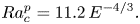
  $E \lesssim 10^{-6}$, which can substantively alter the patterns of convective heat flow. Figure 5(a,b) shows axial vorticity $\omega _z =\vec {e_z}\boldsymbol {\cdot } \vec {\nabla }\times \vec {u}$ snapshots and figure 5(c) latitudinal heat-flux profiles for two $E < 10^{-6}$ simulations with different radius ratios. Convection in the figure 5(a) $r_i/r_o=0.35$ case is sub-critical inside the TC, while it is space-filling in the figure 5(b) $r_i/r_o=0.6$ simulation. In the latter case, polar convection develops as small-scale axially aligned vortices which do not drive jets within the TC. In contrast, the convective motions outside the TC are already sufficiently turbulent in both cases to trigger the formation of zonal jets. These jet flows manifest via the formation of alternating, concentric rings of positive and negative axial vorticity. These coherent zonal motions act to reduce the heat-transfer efficiency in the regions of intense shear where the zonal velocities become of comparable amplitude to the convective flow (e.g. Aurnou et al. Reference Aurnou, Heimpel, Allen, King and Wicht2008; Yadav et al. Reference Yadav, Gastine, Christensen, Duarte and Reiners2016; Guervilly & Cardin Reference Guervilly and Cardin2017; Raynaud et al. Reference Raynaud, Rieutord, Petitdemange, Gastine and Putigny2018; Soderlund Reference Soderlund2019). Thus, the outer-boundary heat-flux profile $Nu_o(\theta )$ in figure 5(c) adopts a strongly undulatory structure exterior to the TC. The asymptotic scaling behaviour of $Nu_e$ is hence intimately related to the spatial distribution and amplitude of the zonal jets that develop in the shell, a topic for future investigations of rotating convective turbulence (e.g. Lonner, Aggarwal & Aurnou Reference Lonner, Aggarwal and Aurnou2022).
(a,b) Meridional sections, equatorial cut and radial surfaces of the axial component of the vorticity  $\omega _z =\vec {e_z}\boldsymbol {\cdot } \vec {\nabla }\times \vec {u}$. Panel (a) corresponds to a numerical model with $r_i/r_o=0.35$, $g=r/r_o$, $E=10^{-7}$, $Ra=10^{11}$ and $Pr=1$, while (b) corresponds to a numerical model with $r_i/r_o=0.6$, $g=(r_o/r)^2$, $E=3\times 10^{-7}$, $Ra=1.3\times 10^{10}$ and $Pr=1$. (c) Local Nusselt number at both spherical-shell boundaries as a function of the colatitude. The orange and blue lines correspond to the numerical model shown in (a,b), respectively. The location of the TC for both radius ratios is marked by vertical solid lines.

Acknowledgements
We thank S. Stellmach and K. Julien for sharing their planar convection data and the reviewers for their constructive comments that improved upon the final manuscript. We also thank the University of Leiden's Lorentz Center, where this study was resuscitated during the ‘Rotating Convection: from the Lab to the Stars’ workshop.
Funding
Simulations requiring longer time integrations to gather diagnostics were computed on GENCI (Grant 2021-A0070410095) and on the S-CAPAD platform at IPGP. JMA gratefully acknowledges the support of the NSF Geophysics Program (EAR 2143939).
Declaration of interests
The authors report no conflict of interest.


 Open access