


Introduction
The growth of emerging fifth-generation (5G) communications networks [Reference Boccardi, Heath, Lozano, Marzetta and Popovski1] and the investments in the “Industry 4.0” scenarios [Reference Palazzi, Correia, Gu, Hemour, Wu, Costanzo, Masotti, Fazzini, Georgiadis, Kazemi, Pereira, Shinohara, Schreurs, Chiao, Takacs, Dragomirescu and Carvalho2] led to a rise in the number of Internet of things (IoT) devices [Reference Markit3]. However, this rise results in an energy consumption crisis, which makes the current energy management approach no longer applicable [Reference Tran and Kaddoum4]. To overcome this, a robust remotely powered system must be developed. Wireless power transfer (WPT) with a dedicated power source can be a promising solution. While the idea of WPT is as old as the 19th century [Reference Marincic5, Reference Shinohara6], among available approaches only RF-WPT can be used for long-range power transmission.
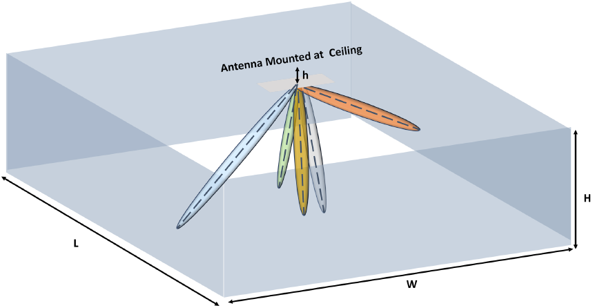
RF-WPT technologies are generally available at low frequencies, since in this domain a low propagation loss is experienced [Reference Liu, Zhang, Boyuan, Gao and Guo7, Reference Palazzi, Hester, Bito, Alimenti, Kalialakis, Collado, Mezzanotte, Georgiadis, Roselli and Tentzeris8]. However, in sub-6 GHz bands, antenna dimensions are large compared to the size of compact IoT devices. Hence, to reduce the size of the system, instead of the sub-6 GHz, mm-wave bands can be employed. Nevertheless, this frequency range suffers from high propagation loss, which must be mitigated to achieve a desirable power level on the receiver side. A focused beam can be used to compensate for this loss. One drawback of transmitting power with a focused beam is its point-to-point transmitting scheme, which restricts the number of users who can receive power simultaneously. As a result, a multibeam solution must be utilized, in which the system can direct the power toward the receiver(s) on demand, as depicted in Fig. 1. Moreover, the architecture of the RF-WPT system is illustrated in Fig. 2. As illustrated, the focus of this work is on the transmitter units and further details regarding the system level operation and receiver unit design are investigated in [Reference Najafabadi, Ghorbanpoor, Vadher, Ramírez, Vorobyov, Nussbaum, Nikolayev, Wang and Skrivervik9].
Multibeam narrow-beamwidth RF-WPT operating scenario for IoT applications.

Block diagram of traditional RF-WPT.

The reconfigurable transmit array proposed in [Reference Qin, Song and Guo10] operates at  $25\,\mathrm{GHz}$ and has a measured gain of $19.6\,\mathrm{dBi}$; by rotating the feed horn, the main beam can be switched to $\pm 15^{\circ}$, $\pm 5^{\circ}$, and 0∘. However, as observed, this solution can only be capable of generating one beam, which is not well suited once multiple beams must be generated simultaneously. In [Reference Park and Ku11], beamforming with four-tone signals is proposed for the microwave power transfer at $5.8\,\mathrm{GHz}$. This solution with 16 array elements can generate multiple beams but at the cost of low gain characteristics. Furthermore, a relatively complex system, including various transitions, is used, which is incompatible with high-frequency ranges. A 4×4 Butler matrix and a transmitter antenna array operating at $2.45\,\mathrm{GHz}$ were used [Reference Carvalho, Georgiadis and (Project)12] to power up rectifiers located in a specific direction. This system has a low level of adjustability, which results in the fixed beam without the possibility of changing the generated beams’ direction.
An earlier version of this paper was presented at the 18th Conference of Antennas and Propagation (EuCAP 2024) and was published in its proceedings [Reference Najafabadi, Ramírez, Ghorbanpoor, Vorobyov, Nussbaum and Skrivervik13]. In this solution, a novel adjustable multibeam dielectric rod antenna design along with the details about the antenna element structure is presented. The proposed solution utilizes the arrangement of five dielectric rod antennas, where each of these rods is directed toward the demanded direction. Each of these rods is fed through an annular slot to achieve a further compact solution. By adjusting the direction of these rods or plugging them in or out, multiple beams can be generated in the specified direction. To illustrate this, a three-beam and a five-beam system are presented. The final five-rod setup is manufactured and measured. The generated beams are directed toward angles between  $-30^{\circ}$ and 30∘. The system has a $-10\,\mathrm{dB}$ impedance bandwidth between $20.3\,\mathrm{GHz}$ and $28.4\,\mathrm{GHz}$, which covers the $24\,\mathrm{GHz}\,\mathrm{ISM}$ band. Furthermore, the adjustable nature of the proposed solution makes it suitable for target-orientated applications in which different scenarios bring up new necessities in the system configuration. Moreover, one of the important factors that need to be considered in this is the environmental impact, since dielectric material is used for the fabrication of the rods and as the substrate, further insight into this matter is available in [Reference Wiklund, Karakoç, Palko, Yiğitler, Ruttik, Jäntti and Paltakari14, Reference Najafabadi, Ramírez, Ghorbanpoor, Vorobyov, Nussbaum and Skrivervik15].
Antenna design
In this section, the simulation results of the annular slot, unit rod antenna, and final multibeam system are presented.
Annular slot design
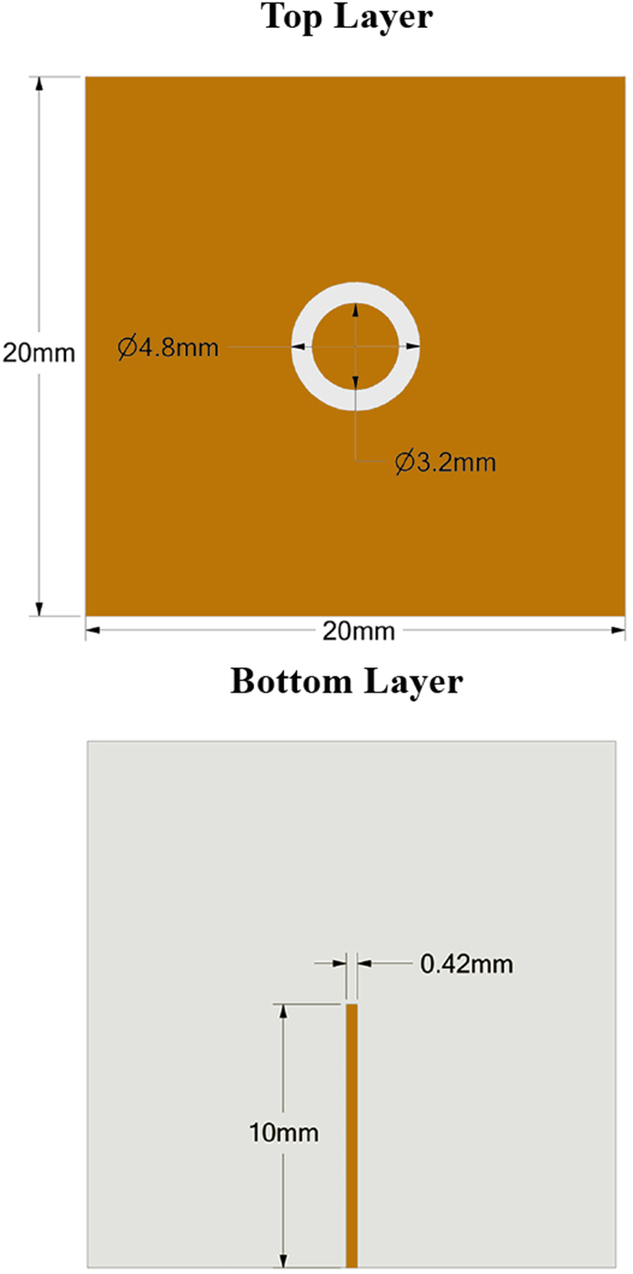
The detailed dimensions of the designed annular slot are shown in Figure 3. The annular slot is designed on a  $0.203\,\mathrm{mm}$ thick “Rogers Corporation RO4003C” ( $\varepsilon_{r} = 3.38$, $\tan\delta~=~0.0027$) substrate. The designed antennas were simulated and optimized in the Ansys $^{\circledR}$ Electronics Desktop HFSS 2023 R1. Without a dielectric rod, the designed annular slot resonance frequency is $29.2\,\mathrm{GHz}$. However, once the dielectric rod is loaded, the resonance frequency is shifted toward $24\,\mathrm{GHz}$. This design provides a wideband bandwidth of $4\,\mathrm{GHz}$ with
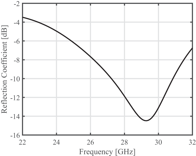
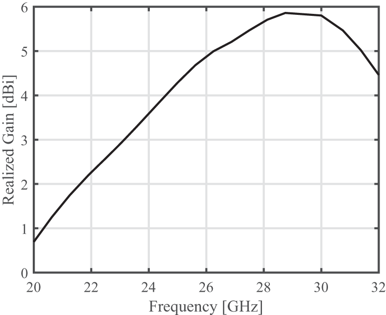
  $S_{11} \lt -10\,\mathrm{dB}$. Figure 4 shows the simulated reflection coefficient of the annular slot, and the peak realized gain between $22\,\mathrm{GHz}$ and $32\,\mathrm{GHz}$ is depicted in Figure 5. The reflection coefficient is below $-10\,\mathrm{dB}$ between $27\,\mathrm{GHz}$ and $31\,\mathrm{GHz}$, while the realized gain is above $5\,\mathrm{dBi}$ in this range.
Annular slot design and its dimensions.

Simulated reflection coefficient and peak realized gain of the annular slot.

Simulated peak realized gain of the annular slot.

Slot-fed dielectric rod antenna design
The designed annular slot is utilized to feed the Rexolite rod ( $\varepsilon_r = 2.53$ and
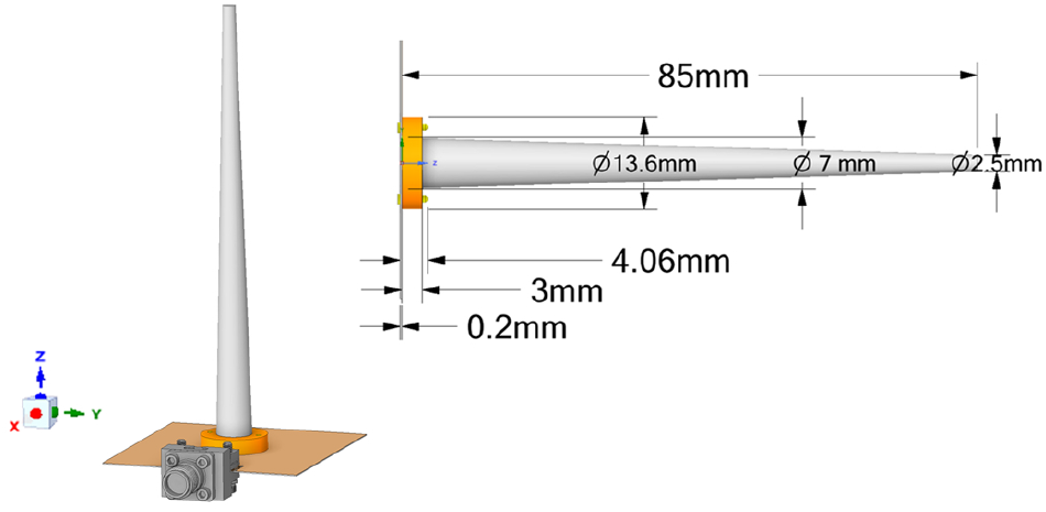
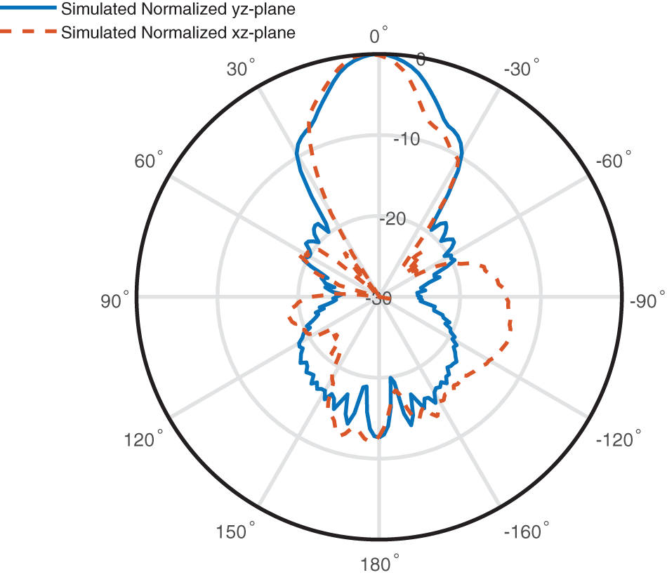
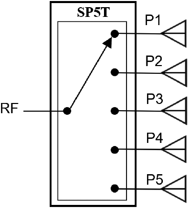
  $\tan \delta = 0.00066$). Figure 6 shows the mechanical drawing of the rod and its detailed dimensions. The rod is designed and optimized to operate at 24 GHz. The simulated radiation pattern of the unit element antenna rod is illustrated in Fig. 7. The gain of the antenna is, while a 3-dB beamwidth of approximately 28∘ is achieved. It is worth mentioning that one of the other merits that must be analyzed thoroughly is the mechanical stability of the system, this requires investigation of the system either theoretically or by relevant measurement procedures, which goes beyond the scope of this paper and will be addressed in future work. Multiple of these rods are used to create the final setup as shown in Fig. 9. The slot is fed through the microstrip line on the bottom layer and via a Southwest 1092-02A-6 end launch connector as illustrated in Fig 9. In order to feed this multibeam structure a simple beamforming network can be used such as a single-pole-five-throw (SP5T) switch as shown in Fig. 8. This type of switch generally has a good isolation and hence a negligible leakage will be experienced. Furthermore, the adjacent elements each have a good inter-port isolation around, which yields a negligible mutual coupling. This is because each of the rods is oriented toward different directions utilizing the conformal arrangement of the rods.
Unit element design of the rod antenna placed on the annular slot.

Unit element rod antenna simulated normalized far-field yz and xz cuts at  $24\,\mathrm{GHz}$.

Possible beamforming network architecture using a SP5T switch.

Plug-in plug-out adjustable multibeam configurations. The mechanical angles in the figure indicate the direction of the rod, which is identical to one of the generated beams.

Multibeam dielectric rod antenna design
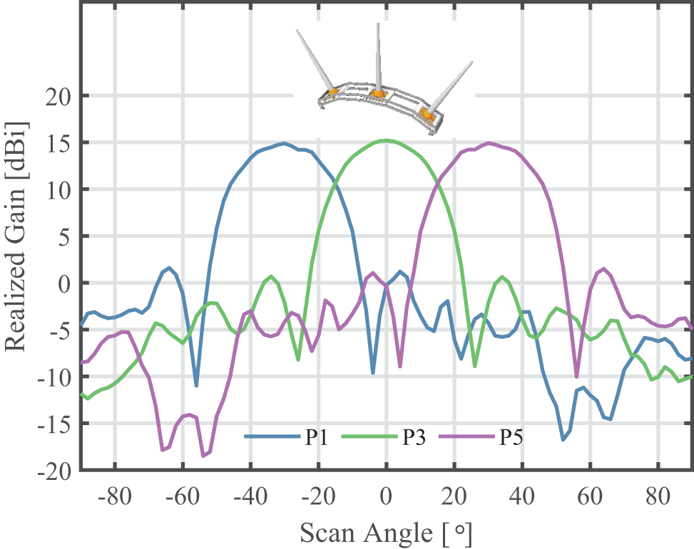
The proposed plug-in plug-out adjustable multibeam configuration is shown in Fig. 9. Configuration A is capable of generating three beams. As shown in Fig. 10, by exciting ports P1, P3, and P5, the corresponding beams at  $-30^{\circ}$, 0∘, and 30∘ are generated, respectively. Furthermore, configuration B is formed by plugging in two more unit rod antenna at $-10^{\circ}$ and 10∘, as depicted in Fig. 9. Configuration B is capable of generating five beams as illustrated in Fig. 11.
Simulated, gain results of the three-beam system versus scan angle at  $24\,\mathrm{GHz}$ and $\phi=90^{\circ}$-plane (yz-plane).

Simulated, gain results of the five-beam system versus scan angle at  $24\,\mathrm{GHz}$ and $\phi=90^{\circ}$-plane (yz-plane).

The simulated beam patterns of multiple beamforming which is generated by feeding all the ports simultaneously are shown in Fig. 12. The additional two beams improve the overall coverage by enhancing the gain level and maintaining a high gain value without a sudden drop in the gain level, which is important in target-dedicated applications. It can also deliver power to two more users simultaneously, which can be adjusted according to the demand. Similarly, the adjustability of the system makes it possible to increase this beam coverage range.
Simulated normalized beam patterns of multiple beamforming.

Measurement and discussion
The unit element rod antenna and the multibeam system are measured in the anechoic chamber of EPFL MAG. The rod is fabricated using a conventional machining process. The distance between the antenna under test (AUT) and transmitter (Tx) was  $1\,\mathrm{m}$.
Air gap issue
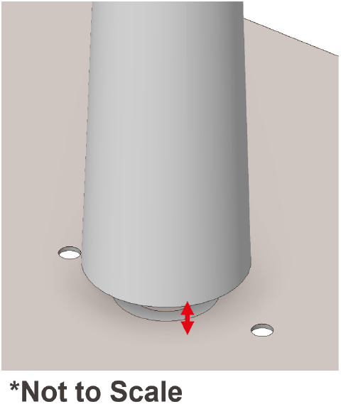
One major problem that occurred employing this design was the undesirable air gap introduced between the board and the dielectric rod as illustrated in Fig. 13. Since the operation frequency is high, this may cause severe effects on the design’s final performance, including the frequency shift. For this reason, this matter is investigated first by not applying any extra adhesive or mechanism to avoid this air gap. Figure 14 shows the simulated results of the single rod with and without a  $100\,\mu\mathrm{m}$ air gap. The measured reflection coefficient illustrated in Fig. 14 is once no air gap removal technique is applied. As it is observable that once no air gap removal technique is applied the measurement results are aligned with the one with an air gap in the simulation. There are several possible techniques that may be applied to reduce and avoid this undesirable effect. However, a simple solution for mitigation of this effect is to apply a layer of adhesive between the rod and the annular slot to avoid the introduction of an air gap in between. For this reason, in our measurements, we take this method into consideration and a thin layer of adhesive is applied between the rod and board.
Possible airgap introduction between the rod and printed circuit board.

Measured and simulated reflection coefficient of the unit element rod antenna with air gap consideration.

Unit element
The unit element rod measured in the anechoic chamber is shown in Fig. 15(a), and the prototype is shown in Fig. 15(b). The reflection coefficient measurements have been done using an Agilent E8361A PNA network analyzer (Fig. 15(a)).
AUT and the fabricated dielectric rod antenna mounted on the board. (a) AUT and the 3D printed support during the radiation pattern measurement. (b) Fabricated Rexolite rod antenna placed on the annular slot.

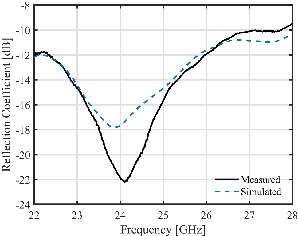
During the radiation pattern measurement, a 3D printed support is used, and the antenna is placed on this structure as shown in Fig. 16 shows the reflection coefficient of the unit element rod antenna. As it is observable, there is a good agreement between the measurement and simulation results. The frequency at which the minimum reflection coefficient value occurs is  $24\,\mathrm{GHz}$, and a below $-10\,\mathrm{dB}$ reflection coefficient is achieved between $22\,\mathrm{GHz}$ and $28\,\mathrm{GHz}$.
Measured and simulated reflection coefficient of the unit element rod antenna.

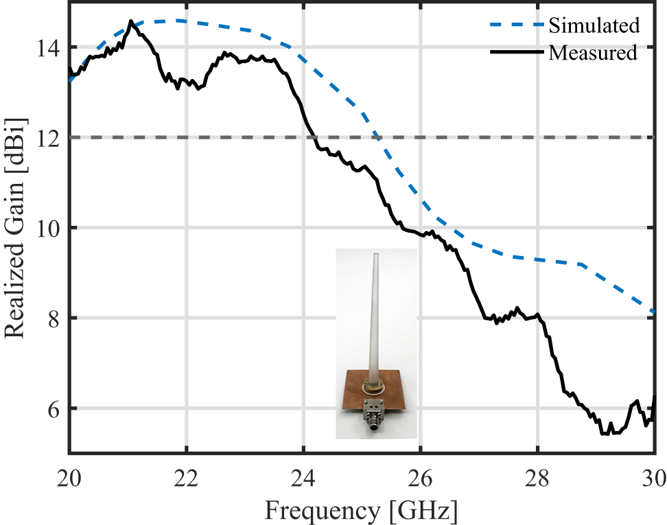
The gain bandwidth of the design is shown in Fig. 17, a  $4\,\mathrm{GHz}$ bandwidth is achieved above $13\,\mathrm{dBi}$ in simulation, while because of the gain drop in the measurement, this bandwidth is achieved with above
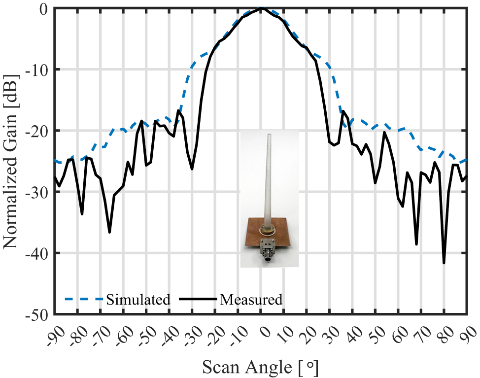
  $12\,\mathrm{dBi}$ threshold. Nevertheless, the normalized radiation pattern of the antenna, as shown in Fig. 18, is in good match with the simulation. The minor gain discrepancy between the simulation and measurement might have occurred due to the effect of the extra layer of adhesive.
Measured and simulated maximum gains of the unit element rod antenna versus frequency.

Measured and simulated normalized gains of unit element rod antenna at  $24\,\mathrm{GHz}$ and $\phi=90^{\circ}$-plane (yz-plane).

Multibeam unit
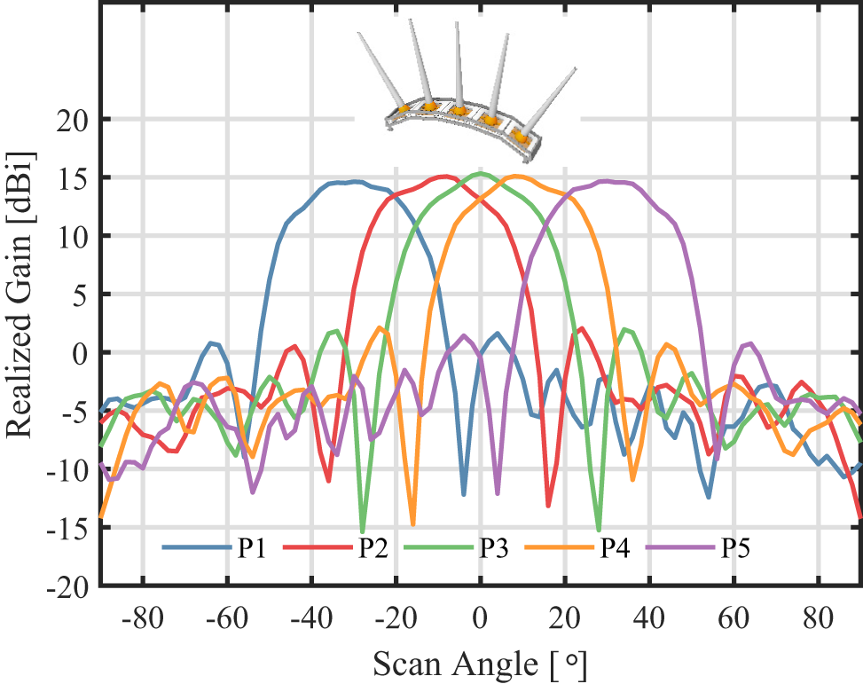
The multibeam rod antenna was measured in the anechoic chamber as shown in Fig. 19(a). Figure 19(b) shows the final prototype elements which each is fabricated separately and finally placed in a 3D printed antenna housing. Each port is matched with  $50\,\Omega$ termination during the radiation pattern measurement, however, this is not mandatory as good isolation between the ports can be achieved as the narrow beamwidth of each identical rod is directed to a different direction. The feeding ports are labeled as P1, P2, P3, P4, and P5. Each of these ports is fed individually during the measurement. However, as P1 and P2 are creating symmetrical counterparts of each beam generated by P4 and P5, results for these ports are not presented. Figure 20 illustrated the beamforming capability of a multibeam rod antenna.
AUT and the fabricated multibeam dielectric rod antenna. (a) Multibeam configuration radiation pattern measurement setup. (b) Fabricated multibeam rod antenna configuration.

Measured and simulated radiation pattern of multibeam rod antenna.

Conclusion
The proposed multibeam dielectric rod antenna solution is low-cost and can generate adjustable beams on demand. The proposed solution is capable of creating a directive beam in the desired direction thanks to its adjustable plug-in plug-out configuration. In this manner, the number of beams required can be adjusted according to the number of targets, that are requesting power simultaneously. The five-rod configuration capable of generating five beams was fabricated and measured. The measured gain value of  $12\,\mathrm{dBi}$ is achieved at $24\,\mathrm{GHz}$, while a $4\,\mathrm{GHz}$ above $12\,\mathrm{dBi}$ radiation bandwidth is achieved. Furthermore, the comparison between the proposed solution and other available dielectric rod designs is available in Table 1. Minor differences between measured and simulated gain are observed which might be due to the extra adhesive layer. The adjustability of the system also helps to introduce, with low complexity, a 2D beam scanning capability in the system. Limited coupling between adjacent elements is observed as each element generates a narrow beam that points to a different angle than that of the adjoining unit. The aforementioned capabilities make the proposed solution a suitable RF power delivery solution for applications in IoT.
Comparison table of available dielectric rod solutions

Acknowledgements
The author would like to thank Patrick OTHENIN-GIRARD and Laurent BEYNON for helping with the machining process and Dany Lemos for fabricating the antenna housing.
Competing interests
The author(s) declare none.

Amir Mohsen Ahmadi Najafabadi received a degree in Amir Mohsen Ahmadi Najafabadi was born on August 1995, in Iran. He is currently a Ph.D. candidate at Ecole Polytechnique Fédérale de Lausanne (EPFL) – Switzerland. He is working under the supervision of Prof. Anja Skrivervik at the MAG Lab of EPFL. He received his M.Sc. degree in the Electronics Engineering Program from Sabancı University – Turkey and his B.Sc. in Electrical and Electronics Engineering from Bilkent University – Turkey. Previously, he worked as a researcher with various research institutes such as CSEM, the Antenna and RF group of Sabanci University, UMRAM, and BOUN Antenna on topics such as mm-wave wireless power transfer, mm-wave 5G antenna design, RF transmitter coil design for MRI and implantable antennas. He has actively contributed to the academic community by serving as a reviewer for numerous prestigious journals and international conferences within his field of expertise. His current research interests are mm-wave antenna design, 5G communication, computational electromagnetic, and bio-electromagnetics.

Germán A. Ramírez received the B.Sc. degree in electronic engineering from Universidad del Quindío, Colombia, in 2004, and the M.Sc. and Ph.D. degrees in telecommunications and in systems and computer engineering from Universidad Nacional de Colombia, Bogotá, Colombia, in 2010 and 2019, respectively. From 2006 to 2017, he was an assistant professor at diverse institutions in Colombia. From 2019 to 2021, he was a visiting researcher at Universitat Politècnica de Catalunya, Spain. Since 2021, he is a research assistant with the Microwaves and Antennas Group of the Ecole Polytechnique Fédérale de Lausanne (EPFL), Lausanne, Switzerland. His research interests include reconfigurable antennas, electrically small antennas, 3D printed antennas, and numerical techniques for electromagnetics.

Mohsen Ghorbanpoor received his B.Sc. and M.Sc. degrees from Sharif University of Technology in 2019 and 2022, respectively. He worked on 77 GHz radar receiver front-end design as his master thesis. He is currently pursuing his Ph.D. in IDEAS group as a collaboration between CSEM and ETHZ with the main focus on long-range wireless power transfer solutions for IoT applications.

Alexander Vorobyov received an M.S. degree in radiophysics and electronics from Kharkiv State University, Ukraine, in 2000. He worked as an Assistant Lecturer at Kharkiv Academy of Fire Safety from 2002 to 2003, focusing on remote sensing of natural raw materials. In 2004, he joined Delft University of Technology, where he earned a Ph.D. in electrical engineering in 2008. Subsequently, he became a Post-Doctoral Research Associate at IETR Rennes, France, working on automotive radar antenna arrays with MEMS-based phase shifters. Since 2012, he has been with the “Wireless Embedded Systems” group at CSEM, Switzerland, as an expert. His research interests include applied electromagnetism, antenna design and optimization, radio wave propagation, BAN communication, RF sensing, and wireless power transmission across diverse environments.

Pascal Nussbaum has graduated as an Electronic Engineer in Neuchâtel, Switzerland. He joined CSEM in 1990 where he has been successively involved in IC design tools development, digital and mixed-mode IC design, CMOS imagers, and embedded vision/AI systems. He participated in two startups, respectively, focused on mobile phones for cognitively impaired people and vision sensors for buildings surveillance and automation. He has also been active in the toys and digital television industries and currently leads the Smart Connected Systems group at CSEM, with a focus on sustainable electronics and wireless power transfer (WPT).

Anja Skrivervik obtained her master’s degree in electrical engineering from Ecole Polytechnique Fédérale de Lausanne in 1986, and her Ph.D. from the same institution in 1992, for which she received the Latsis award. After a stay at the University of Rennes as an invited Research Fellow and 2 years in the industry, she returned to EPFL as an Assistant Professor in 1996, and is now a Professeur Titulaire at this institution. In addition, she was a visiting professor at the University of Lund from 2021 to 2024. Her teaching activities include courses on microwaves and antennas. Her research activities include electrically small antennas, implantable and wearable antennas, multifrequency and ultra wideband antennas, and numerical techniques for electromagnetics. She is author or co-author of more than 250 peer-reviewed scientific publications. She is very active in European collaboration and European projects. She was the chairperson of the Swiss URSI until 2012, is a Board member of the European School on Antennas, and is frequently requested to review research programs and centers in Europe. She was member of the board of directors of the European Association on Antennas and Propagation (EurAAP) from 2017 to 2022.


 Open access