


1. Introduction
Droplet impacts with superhydrophobic surfaces formed of arrays of pillars have been widely studied experimentally because of the self-cleaning, droplet repellent properties of such surfaces (Tsai et al. Reference Tsai, van der Veen, van de Raa and Lohse2010; Maitra et al. Reference Maitra, Antonini, Auf der Mauer, Stamatopoulos, Tiwari and Poulikakos2014a,Reference Maitra, Tiwari, Antonini, Schoch, Jung, Eberle and Poulikakosb). To understand the performance and durability of superhydrophobic substrates, it is necessary to understand how a droplet penetrates between the substrate asperities, and in this area the work of van der Veen et al. (Reference van der Veen, Hendrix, Tran, Sun, Tsai and Lohse2014), who used high-speed colour interferometry to experimentally measure in situ free-surface profiles as a droplet impacts a substrate with microstructures, is of particular importance. Characteristic impact velocities in droplet impact experiments tend to be less than  $5\,{\rm m}\,{\rm s}^{-1}$. However, there are applications, such as preventing ice accretion on flying aircraft, where it would be highly desirable to operate superhydrophobic surfaces in significantly higher-velocity droplet impact regimes. Existing superhydrophobic surfaces are easily damaged at higher droplet impact speeds (Wang et al. Reference Wang, Zhang, Sun, Kalulu, Chen, Zhou and Jiang2019), lessening their long-term effectiveness. Consequently, motivated by the desire to design and create more durable superhydrophobic surfaces, the current paper seeks to determine the pressures, loads and moments on individual substrate elements, to improve understanding of the forces superhydrophobic substrates would need to withstand in higher-velocity impacts.
Beyond superhydrophobic surfaces, more general wetting of rough and textured substrates by droplets has also garnered much attention (Dash, Alt & Garimella Reference Dash, Alt and Garimella2012), albeit usually in regimes of much slower water ingress compared with the violent droplet impacts considered herein. At slower impact speeds a droplet may initially rest on top of an array of substrate asperities in what is called the Cassie–Baxter wetting state, with the droplet transitioning to the Wenzel wetting state when the substrate asperities impale the droplet and become completely wet (Whyman & Bormashenko Reference Whyman and Bormashenko2011).
Droplet impacts with surface roughness also critically alter the subsequent splashing behaviour. With rough surfaces, the regular corona splash associated with droplet impacts with smooth surfaces is lost and instead roughness can trigger prompt splashing with microdroplets ejected ahead of the advancing contact line (Josserand et al. Reference Josserand, Lemoyne, Troeger and Zaleski2005; Xu Reference Xu2007). The height of the roughness also critically effects whether a droplet will splash or spread over a surface (Garcıa-Geijo et al. Reference Garcıa-Geijo, Quintero, Riboux and Gordillo2021). The splash formed in a droplet impact can also be significantly altered by changing the distribution of micropillars covering a substrate (Tsai et al. Reference Tsai, Hendrix, Dijkstra, Shui and Lohse2011; Tan Reference Tan2017), the wetting properties of the substrate (Josserand & Thoroddsen Reference Josserand and Thoroddsen2016) or by allowing the substrate to deform (Howland et al. Reference Howland, Antkowiak, Castrejón-Pita, Howison, Oliver, Style and Castrejón-Pita2016; Pegg, Purvis & Korobkin Reference Pegg, Purvis and Korobkin2018).
For surfaces which are porous, rather than rough, the penetration of fluid into the porous medium beneath the substrate surface has been investigated (Clarke et al. Reference Clarke, Blake, Carruthers and Woodward2002; Reis, Griffiths & Santos Reference Reis, Griffiths and Santos2008) and is relevant to coating problems and soil erosion. Simple geometries such as a flat substrate with a single pore have been investigated experimentally (Delbos, Lorenceau & Pitois Reference Delbos, Lorenceau and Pitois2010; de Jong, Enríquez & van der Meer Reference de Jong, Enríquez and van der Meer2015) and numerically (Ding & Theofanous Reference Ding and Theofanous2012). Similarly, for the earliest post-impact times, wire meshes and individual fibres (as seen in the experiments of Boscariol et al. (Reference Boscariol, Chandra, Sarker, Crua and Marengo2018), Xu et al. (Reference Xu, Xie, He, Cheng and Liu2017) and Kim & Kim Reference Kim and Kim2016), are further examples of non-flat surfaces, albeit ones through which liquid can ultimately pass through at later times in the impact due to the absence of an impermeable base.
Wagner theory will be used to investigate theoretically the free-surface and pressure evolution associated with inertially dominated droplet impacts with non-flat substrates. Wagner theory was originally developed to investigate the forces experienced by seaplanes landing on water (Wagner Reference Wagner1932), and with this heritage, the formal development of the theory was motivated by water-entry problems, in particular ship slamming. Using matched asymptotic expansions Cointe & Armand (Reference Cointe and Armand1987), Howison, Ockendon & Wilson (Reference Howison, Ockendon and Wilson1991) and Oliver (Reference Oliver2002) coupled the larger-scale behaviour in the liquid to a liquid splash jet and a jet root region. Solutions for the water entry of a wedge and a circular body are well known, while Ross & Hicks (Reference Ross and Hicks2019) recently determined the Wagner solution for the water entry of a two-dimensional symmetric power-law-shaped body. The theory has been extended by Scolan et al. (Reference Scolan, Coche, Coudray and Fontaine1999) to consider the water entry of asymmetric two-dimensional body shapes. Axisymmetric solutions were investigated by Oliver (Reference Oliver2002), while genuinely three-dimensional Wagner solutions for water-entry problems are rare, although Korobkin (Reference Korobkin2002) solves the impact problem for an elliptical–paraboloid-shaped body, and further results for three-dimensional impacts are given by Scolan & Korobkin (Reference Scolan and Korobkin2001), Korobkin & Scolan (Reference Korobkin and Scolan2006) and Tassin et al. (Reference Tassin, Jacques, El Malki Alaoui, Nême and Leblé2012).
Even though rough substrates are considered herein, Wagner theory assumes the liquid surface and the impactor are nearly parallel. Consequently, our attention is restricted to small times after impact with a substrate in which the height of the roughness and the vertical displacement of the liquid surface are both much smaller than the horizontal extent of the contact region. To study impacts with rough surfaces, it is necessary to investigate impacts involving multiple impact sites. Even in two dimensions, Wagner-style analyses of liquid–solid impacts involving multiple impact sites are less common. Korobkin (Reference Korobkin1996) considered the water-entry problem for a two-dimensional body with a dimple at its leading edge, leading to a pair of symmetric impact sites some horizontal distance away from the body centreline, while Korobkin & Khabakhpasheva (Reference Korobkin and Khabakhpasheva2006) investigate wave impacts on a finite elastic beam and consider cases where there are impacts at both ends of the beam, trapping a cavity between a pair of inner contact lines. Additionally, in the context of modelling impacts of sloshing liquefied natural gas with containment systems, Khabakhpasheva, Korobkin & Malenica (Reference Khabakhpasheva, Korobkin and Malenica2013) consider the impact of a liquid with a corrugated tank wall, consisting of a pair of rounded elements protruding beneath a flat plate.
In addition to modelling water-entry problems, Wagner theory has previously been applied to droplet impacts with liquid layers (Howison et al. Reference Howison, Ockendon, Oliver, Purvis and Smith2005; Purvis & Smith Reference Purvis and Smith2005) and droplet impacts with flexible substrates (Pegg et al. Reference Pegg, Purvis and Korobkin2018; Khabakhpasheva & Korobkin Reference Khabakhpasheva and Korobkin2020). Surface roughness in droplet impacts has previously been incorporated into Wagner theory by Ellis, Smith & White (Reference Ellis, Smith and White2011). However, this study restricted attention to roughness elements some horizontal distance away from the initial impact site, with the droplet initially touching down on a flat substrate midway between a pair of symmetric roughness elements. Elliott & Smith (Reference Elliott and Smith2017) also incorporated the growth of ice at the droplet impact site in an extension of Wagner theory relevant to aircraft icing. Much of this work is restricted to idealised two-dimensional droplets, although axisymmetric droplet impacts with completely flat substrates have also been investigated (Philippi, Lagrée & Antkowiak Reference Philippi, Lagrée and Antkowiak2016).
Lowering the ambient gas pressure surrounding the droplet reduces the propensity for the droplet to splash upon impact (Xu, Zhang & Nagel Reference Xu, Zhang and Nagel2005). However, herein we assume that the gas surrounding the impact site has a negligible impact on the impact dynamics. Hicks & Purvis (Reference Hicks and Purvis2017) considered pre-impact gas cushioning in droplet impacts with a thin layer of porous media, recognising that a periodic array of substrate protuberances can be considered as a porous medium on certain length scales.
Initially, a violent impact of an idealised two-dimensional droplet with a single substrate element will be considered, before progressing on to investigate a pair of impacts with a substrate. The extent of the wetted surface and the free-surface profile will be determined, as well as the pressure distribution, load and moment on each substrate element. This will assist predictions of the material properties required for durable superhydrophobic substrates. In § 2 the assumptions underpinning the model are described as well as the boundary conditions on the wetted contact patch and the free portions of the droplet surface. Section 3 describes mixed boundary value problems for the displacement and velocity potentials associated with a droplet impact with a single asymmetric impact site, before applying the results obtained to droplet impacts with scaled substrate geometries corresponding to an inclined plane, a quadratic substrate element and a quartic substrate element. Section 4 considers a double droplet impact with a symmetric substrate, which results in a symmetric pair of touchdown sites. After developing the corresponding mixed boundary value problems, impacts with the interior of a wedge and a pair of quadratic substrate elements are considered, and comparisons drawn with the corresponding impact for a single substrate element of equivalent shape. Section 5 extends this analysis to consider an asymmetric substrate and a corresponding pair of asymmetric impacts. Further conclusions and avenues for future work are discussed in § 6, where the key novelties of the paper are also highlighted.
2. Modelling preliminaries
The first touchdown of an initially circular two-dimensional droplet of radius  $R$, occurs at time $\tilde {t} = 0$. At touchdown, the undisturbed droplet free surface $\tilde {h}\!\left ( \tilde {x},\tilde {t} \right )$ is assumed to be at
 \begin{equation} \tilde{h}\!\left( \tilde{x},\,0 \right) ={\pm} \sqrt{R^2 - \tilde{x}^2} + R - \tilde{h}_0, \end{equation}
where  $\tilde {x}$ is the horizontal distance along the substrate and the vertical offset $\tilde {h}_0$ is chosen to ensure the droplet and substrate are in contact at $\tilde {t}=0$. The initial impact of the lower surface of the droplet with the substrate surface $\tilde {s}\!\left ( \tilde {x},\tilde {t} \right )$, occurs at $(\tilde {x}_0,\tilde {y}_0)$, where
 \begin{equation} \tilde{y}_0 = \tilde{h}\!\left( \tilde{x}_0,0 \right) = \tilde{s}\!\left( \tilde{x}_0,0 \right). \end{equation}
The substrate is assumed to be differentiable at the initial impact site and so tangents to the substrate and lower droplet free surface are required to be parallel at the initial impact site, i.e.
 \begin{equation} \frac{\partial \tilde{s}}{\partial \tilde{x}}\!\left( \tilde{x}_0,0 \right) = \frac{\partial \tilde{h}}{\partial \tilde{x}}\!\left( \tilde{x}_0,0 \right). \end{equation}
 Attention is restricted to cases in which the horizontal extent of the touchdown region  $L$, is much smaller than the droplet radius. This ensures the initial touchdown is close to the bottom of the droplet, where the droplet free surface and substrate are nearly parallel. In this regime, a small parameter
 \begin{equation} \varepsilon = \frac{L}{R} \ll 1, \end{equation}
can be defined. Geometrical considerations imply vertical length scales associated with the substrate are  ${O}\!\left (\varepsilon ^2 R\right )$, and this length scale is used to non-dimensionalise both the substrate and the droplet free-surface height close to the impact site. The remaining length scales in the droplet are non-dimensionalised using the horizontal distance to the initial impact site $\varepsilon R$, while velocities are non-dimensionalised using the relative normal closure speed between the droplet and substrate $U$. The time scale $\varepsilon ^2 R/U$, necessary for the droplet to traverse the height of the substrate asperities is used to non-dimensionalise time, while a pressure scale $\varepsilon ^{-1} \rho U^2$ ensures the non-dimensional pressure is retained in the leading-order problem for small $\varepsilon$. Here, $\rho$ is the liquid density. Similarly, the characteristic velocity potential is taken to be ${O}\!\left (\varepsilon R U\right )$, to retain this term at leading order in $\varepsilon$. Tildes on variables are dropped when the non-dimensionalisation takes place. For a water droplet of radius $R=1$ mm and impact speed $U=10\,{\rm m}\,{\rm s}^{-1}$, the Reynolds number $\rho U R/\mu \sim 10^4$, the Weber number $\rho U^2 R/\sigma \sim 10^3$ and the Froude number $U/\sqrt {g R} \sim 10^2$, where $\mu$ is the liquid viscosity, $\sigma$ is the surface tension coefficient of the liquid interface and $g$ is the acceleration due to gravity. Hence, to leading order, the effects of viscosity, surface tension and gravity are neglected.
Working initially in the frame of reference in which the droplet appears stationary in the far field with the substrate moving vertically up towards the droplet at constant velocity, if the liquid is incompressible, then the non-dimensional liquid velocity potential  $\bar {\phi }$ satisfies Laplace's equation
 \begin{equation} \frac{\partial ^2 \bar{\phi}}{\partial x^2} + \frac{\partial ^2 \bar{\phi}}{\partial y^2} = 0. \end{equation}
It is frequently convenient to work in terms of the displacement potential of Korobkin & Pukhnachov (Reference Korobkin and Pukhnachov1988), which is defined to be
 \begin{equation} \varPhi ={-}\int_0^t \bar{\phi}\!\left( x,y,\tau \right)\mathrm{d}\tau, \end{equation}
and consequently, the non-dimensional liquid displacement potential also satisfies Laplace's equation with
 \begin{equation} \frac{\partial ^2 \varPhi}{\partial x^2} + \frac{\partial ^2 \varPhi}{\partial y^2} = 0. \end{equation}
In the definition of the displacement potential a time origin is chosen, which corresponds to the instant of initial touchdown. In this frame of reference, the non-dimensional liquid free surface will be denoted  $\bar {h}\!\left ( x,t \right )$, while the initially undisturbed free-surface position is given by
 \begin{equation} \bar{h}\!\left( x,0 \right) = \tfrac{1}{2} x^2 - h_0. \end{equation}
For non-flat substrates, the initial touchdown may not occur at  $y=0$, although a simple vertical coordinate transformation can return the height of the initial touchdown site to $y=0$.
In the alternative frame of reference where the droplet descends towards a stationary substrate  $S\!\left ( x \right )$, the corresponding free-surface profile is given by
 \begin{equation} h\!\left( x,t \right) = \bar{h}\!\left( x,t \right) - t. \end{equation}
Given the disparate horizontal and vertical characteristic length scales associated with the substrate,  ${O}\!\left (1\right )$ substrate gradients in the non-dimensional coordinate system correspond to ${O}\!\left (\varepsilon \right )$ gradients in the dimensional coordinate system, so the geometric assumptions on the impact necessary for the application of Wagner theory are satisfied. In the frame of reference in which the droplet is stationary in the far field and the substrate moves towards the droplet, the substrate profile $s\!\left ( x,t \right )$ satisfies
 \begin{equation} s\!\left( x,t \right) = S\!\left( x \right) + t. \end{equation}
Similarly, the velocity potential in the frame of reference in which the droplet appears stationary in the far field  $\bar {\phi }$, is related to the velocity potential in a frame of reference in which the substrate appears stationary $\phi$, through the equation
 \begin{equation} \phi\!\left( x,y,t \right) = \bar{\phi}\!\left( x,y,t \right) - y, \end{equation}
and in particular  $\phi \!\left ( x,0,t \right ) = \bar {\phi }\!\left ( x,0,t \right )$ on the interface $y=0$.
Both the velocity and displacement potentials satisfy mixed boundary value problems, with different boundary conditions on the droplet surface depending on whether the droplet locally makes a wetted contact with the substrate or whether the droplet surface is a boundary with the surrounding gas. As with earlier studies by Purvis & Smith (Reference Purvis and Smith2005) and Howison et al. (Reference Howison, Ockendon, Oliver, Purvis and Smith2005), we assume that the surrounding gas does not induce a pressure on the droplet free surface to leading order. Consequently, the liquid pressure  $p = 0$ on the free surface. To leading order in $\varepsilon$, Bernoulli's equation implies
 \begin{equation} \frac{\partial \bar{\phi}}{\partial t} ={-}p. \end{equation}
Upon integrating this expression with respect to time, we find that the velocity potential
 \begin{equation} \bar{\phi} = 0, \end{equation}
on the droplet free surface. Given the definition of the displacement potential (2.6), a further integration in time implies that the displacement potential
 \begin{equation} \varPhi = 0, \end{equation}
on the droplet free surface. Differentiating the velocity and displacement potential with respect to  $x$ on the droplet free surface implies
 \begin{equation} \frac{\partial \bar{\phi}}{\partial x} = 0 \quad \mbox{and} \quad \frac{\partial \varPhi}{\partial x} = 0. \end{equation}
On the free surface, as there is zero horizontal liquid velocity to leading order, the kinematic boundary condition implies
 \begin{equation} \frac{\partial \bar{\phi}}{\partial y} = \frac{\partial \bar{h}}{\partial t}\!\left( x,t \right). \end{equation}
Using the definition of the displacement potential (2.6) and integrating the velocity potential on the free surface with respect to time, from  $t=0$, when the undisturbed droplet free surface $\bar {h}\!\left ( x,0 \right ) = \frac {1}{2} x^2 - h_0$, to a general time in which the free-surface position is $\bar {h}\!\left ( x,t \right )$ implies
 \begin{equation} \frac{\partial \varPhi}{\partial y} = \frac{1}{2} x^2 - \bar{h}\!\left( x,t \right) - h_0, \end{equation}
on the droplet free surface.
On the wetted surface, the vertical velocity of the liquid must equal the upwards vertical velocity of the substrate, and so
 \begin{equation} \frac{\partial \bar{\phi}}{\partial y} = 1. \end{equation}
The displacement potential on the wetted surface evolves from the undisturbed droplet free surface (2.8) when  $t=0$, to the shaped of the substrate shape (2.10) at time $t$, and consequently,
 \begin{equation} \frac{\partial \varPhi}{\partial y} = \frac{1}{2} x^2 - S\!\left( x \right) - t - h_0, \end{equation}
on the wetted surface. In the frame of reference in which the droplet appears stationary in the far field
 \begin{equation} \bar{\phi} \rightarrow 0, \quad \mbox{and} \quad \varPhi \rightarrow 0, \quad \mbox{as} \ \sqrt{x^2 + y^2} \rightarrow \infty, \end{equation}
while
 \begin{equation} \bar{h}\!\left( x,t \right) \sim \frac{1}{2} x^2 - h_0, \quad \mbox{and} \quad \frac{\partial \bar{h}}{\partial t} \rightarrow 0, \quad \mbox{as} \ \left| x \right| \rightarrow \infty. \end{equation}
 Herein, attention will be restricted to substrate geometries  $S\!\left ( x \right )$ that are continuous in $x$ throughout any wetted contact patches and consequently, in the limit of small $\varepsilon$, both the velocity potential and the displacement potential are bounded at the contact lines, which mark the transition from a wetted portion of the substrate to the droplet free surface. In particular, at the contact lines, the Wagner condition is satisfied with the droplet free surface meeting the substrate at leading order. As both the displacement potential $\varPhi$ and the velocity potential $\bar {\phi }$ satisfy the two-dimensional Laplace equation, following Moore, Ockendon & Oliver (Reference Moore, Ockendon and Oliver2013), complex functions $W\!\left ( z,t \right ) = \varPhi \!\left ( x,y,t \right ) + \mathrm {i} \varPsi \!\left ( x,y,t \right )$ and $w\!\left ( z,t \right ) = \bar {\phi }\!\left ( x,y,t \right ) + \mathrm {i} \bar {\psi }\!\left ( x,y,t \right )$, are defined, where $z = x + \mathrm {i} y$. Here $\varPsi$ is the complex conjugate of $\varPhi$, while the complex conjugate of $\bar {\phi }$, is the streamfunction $\bar {\psi }$.
3. Impacts with a single asymmetric touchdown site
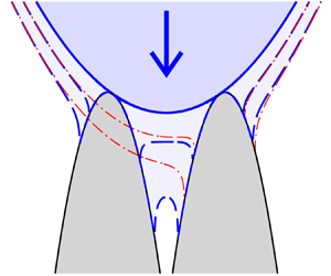
A droplet impact with as single impact site, such as that shown in figure 1, is initially investigated. At touchdown the undisturbed droplet free-surface shape is given by (2.8). After impact, the contact line positions will be denoted  $a(t)$ and $b(t)$, with the wetted surface occupying $a(t) < x < b(t)$, and the droplet free surfaces occupying $x < a(t)$ and $x > b(t)$.
Schematic of an asymmetric droplet impact with a non-flat substrate with a single wetted surface. Showing (a) the instant of initial touchdown  $t=0$, and (b) the configuration for $t > 0$.

3.1. The free surface of the droplet
The droplet free-surface position is obtained from the mixed boundary value problem for the displacement potential with a single impact site, which is summarised in figure 2. If a characteristic function
 \begin{equation} \varLambda\!\left( z,t \right) = \sqrt{\left(z - b(t)\right)\left(z - a(t)\right)}, \end{equation}
is defined with a branch cut along the  $x$-axis between $a(t)$ and $b(t)$, then Cauchy's integral formula applied to $W_z\!\left ( z,t \right )$ can be inverted to give
 \begin{equation} \varPhi_x\!\left( x,y,t \right) - \mathrm{i} \varPhi_y\!\left( x,y,t \right) = \frac{\varLambda\!\left( z,t \right)}{2 {\rm \pi}\mathrm{i}} \oint_\gamma \frac{ \left[\varPhi_\xi\!\left( \xi,\eta,t \right) - \mathrm{i} \varPhi_\eta\!\left( \xi,\eta,t \right)\right]\mathrm{d}\zeta}{\varLambda\!\left( \zeta,t \right) \left(\zeta - z\right)}, \end{equation}
where the variable of integration  $\zeta = \xi + \mathrm {i} \eta$ (Gakhov Reference Gakhov1966). The contour $\gamma$ is taken to be a counter clockwise semi-circular arc in the upper half-space with a return that runs along the $x$-axis. As the displacement potential is continuous across the contact lines at $x=a(t)$ and $x=b(t)$, the consistency conditions
 \begin{equation} \oint_\gamma \frac{ \left[\varPhi_\xi\!\left( \xi,\eta,t \right) - \mathrm{i} \varPhi_\eta\!\left( \xi,\eta,t \right)\right] \zeta^n\,\mathrm{d}\zeta}{\varLambda\!\left( \zeta,t \right)} = 0, \end{equation}
must additionally be satisfied for  $n=0$ and $n=1$.
The mixed boundary value problem for the displacement potential in an impact with a single touchdown site upon a substrate with shape  $S\!\left ( x \right )$. The far-field behaviour of the displacement potential and the free-surface position are given in the rectangular box.

As  $z \rightarrow x + \mathrm {i} 0$ from positive values of $y$, the characteristic function
 \begin{equation} \varLambda\!\left( x + \mathrm{i} 0,t \right) = \begin{cases} \sqrt{\left(x - b(t)\right) \left(x - a(t)\right)} & \mbox{for} \ x > b(t), \\ \mathrm{i} \sqrt{\left(b(t) - x\right) \left(x - a(t)\right)} & \mbox{for} \ a(t) < x < b(t), \\ -\sqrt{\left(x - b(t)\right) \left(x - a(t)\right)} & \mbox{for} \ x < a(t). \end{cases} \end{equation}
Given the definition of  $\gamma$, the imaginary part of (3.2) implies
 \begin{align} \bar{h}\!\left( x,t \right) &= \frac{x^2}{2} - h_0 \nonumber\\ &\quad + \frac{\,\mathrm{sgn}\!\left( x - x_0 \right) \sqrt{\left(x - b(t)\right)\left(x - a(t)\right)}}{\rm \pi} \int_{a(t)}^{b(t)} \frac{\frac{1}{2} \xi^2 - t - S\!\left( \xi \right) - h_0 \,\mathrm{d}\xi}{\sqrt{\left(b(t) - \xi\right)\left(\xi - a\right)} \left(\xi - x\right)}, \end{align}
for  $x < a(t)$ or $x > b(t)$, where the boundary condition (2.19) is applied to the wetted surface and the boundary conditions (2.15b) and (2.17) are applied to the droplet free surface. Here, $x_0$ is the horizontal location of the initial impact site. Similarly, the real part of the consistency condition (3.3) implies
 \begin{equation} \int_{a(t)}^{b(t)} \frac{\left[\frac{1}{2} \xi^2 - S\!\left( \xi \right) - t - h_0\right] \xi^n \,\mathrm{d}\xi}{\sqrt{\left(b(t) - \xi\right)\left(\xi - a(t)\right)}} = 0, \end{equation}
for  $n=0$ and $n=1$.
Except for the terms involving the substrate shape  $S\!\left ( x \right )$ and the vertical offset $h_0$, all the terms in the integrals (3.5) and (3.6) match those obtained for a droplet impact with a flat plate (which corresponds to $S\!\left ( x \right ) = 0$ and $h_0 = 0$). For $S\!\left ( x \right ) = 0$, the impact is symmetric with $a(t) = -b(t)$ and so the well-known solution for impact with a flat plate is obtained. Equation (2.9) can be used to transform the droplet free surface given in (3.5) into a frame of reference in which the droplet approaches impact with a stationary substrate. In this alternative frame of reference, the droplet free-surface profile is given by
 \begin{align} h\!\left( x,t \right) &=\frac{1}{2} \,\mathrm{sgn}\!\left( x - x_0 \right) \sqrt{\left(x - b(t)\right)\left(x - a(t)\right)} \nonumber\\ &\quad \times \left(x + \frac{1}{2} \left(a(t) + b(t)\right) - \frac{2}{\rm \pi} \int_{a(t)}^{b(t)} \frac{S\!\left( \xi \right) \mathrm{d}\xi}{\sqrt{\left(b(t) - \xi\right)\left(\xi - a(t)\right)} \left(\xi - x\right)}\right), \end{align}
for  $x < a(t)$ and $x > b(t)$. The consistency condition (3.6) for $n=0$ implies
 \begin{equation} 3 b(t)^2 + 2 a(t) b(t) + 3 a(t)^2 - 16 \left(t + h_0\right) - \frac{16}{\rm \pi} \int_{a(t)}^{b(t)} \frac{S\!\left( \xi \right) \mathrm{d}\xi}{\sqrt{\left(b(t) - \xi\right)\left(\xi - a(t)\right)}} = 0, \end{equation}
while the consistency condition (3.6) for  $n=1$ is given by
 \begin{align} &\left(b(t) + a(t)\right)\left(5 b(t)^2 - 2 a(t) b(t) + 5 a(t)^2\right) - 16 \left(b(t) + a(t)\right) \left(t + h_0\right) \nonumber\\ &\quad - \frac{32}{\rm \pi} \int_{a(t)}^{b(t)} \frac{S\!\left( \xi \right) \xi \,\mathrm{d}\xi}{\sqrt{\left(b(t) - \xi\right)\left(\xi - a(t)\right)}} = 0. \end{align}
Given a substrate shape  $S\!\left ( x \right )$, (3.8a) and (3.8b) determine the contact line position at a given time. Once the initial touchdown site $x_0$, and the subsequent evolution of the contact lines have been determined, (3.7) gives the free-surface position. For even functions $S\!\left ( x \right )$, (3.8b) is automatically satisfied as the impact is symmetric with $a(t) = -b(t)$.
Scolan et al. (Reference Scolan, Coche, Coudray and Fontaine1999) developed an alternative method for studying asymmetric water-entry problems by applying Cauchy's integral formula and the contour used herein to the function  $\sqrt {\left (z - b(t)\right )\left (z - a(t)\right )} \left (\varPhi _x - \mathrm {i} \varPhi _y\right )$. The requirement that the displacement potential is bounded at the contact lines gives rise to an alternative pair of integral equations. For each body shape investigated herein, the contact line evolution found using (3.8a) and (3.8b), is validated by comparing the evolution with that obtained using the method of Scolan et al. (Reference Scolan, Coche, Coudray and Fontaine1999). Further validation of the solution of (3.8a) and (3.8b) is obtained by differentiating these equations to form a two-by-two system of linear equations for the unknown contact line velocities $\dot {a}(t)$ and $\dot {b}(t)$ (see Appendix B). At $t=0$ the contact line velocities are unbounded, so this system of equations cannot be integrated from the instant of touchdown. However, for any time $t > 0$, an initial condition for the contact line positions can be obtained from (3.8a) and (3.8b) and then the contact line velocities can be integrated forward and backwards in time to recover the full contact line evolution.
3.2. The pressure on the wetted surface
The pressure on the wetted surface is obtained from a mixed boundary value problem formulated for the velocity potential, which is summarised in figure 3.
The mixed boundary value problem for the velocity potential in an impact with a single touchdown site upon a substrate with shape  $S\!\left ( x \right )$. The far-field behaviour of the velocity potential and the free-surface velocity are given in the rectangular box.

As derivatives of the velocity potential are expected to be unbounded at the contact lines, Cauchy's integral formula applied to  $w_z\!\left ( z,\,t \right )$ can be inverted to give
 \begin{align} \bar{\phi}_x\!\left( x,y,t \right) - \mathrm{i} \bar{\phi}_y\!\left( x,y,t \right) &= \frac{1}{2 {\rm \pi}\mathrm{i} \varLambda\!\left( z,t \right)} \oint_\gamma \frac{\varLambda\!\left( \zeta,t \right) \left[\bar{\phi}_\xi\!\left( \xi,\eta,t \right) - \mathrm{i} \bar{\phi}_\eta\!\left( \xi,\eta,t \right)\right]\,\mathrm{d}\zeta}{\zeta - z} \nonumber\\ &\quad + \frac{P_0}{\varLambda\!\left( z,\,t \right)}, \end{align}
where the characteristic function is given by (3.1),  $\gamma$ is as before and $P_0$ is a constant (Gakhov Reference Gakhov1966). Furthermore, as $\bar {\phi } \rightarrow 0$ as $x \rightarrow \infty$, it is necessary to take $P_0 = 0$.
The characteristic function  $\varLambda \!\left ( z \right )$ is given by (3.4) as $z \rightarrow x + \mathrm {i} 0$ from positive values of $y$. Consequently, the real part of (3.9) implies
 \begin{equation} \bar{\phi}_x\!\left( x,0,t \right) ={-}\frac{1}{{\rm \pi} \sqrt{(b(t) - x)(x - a(t))}} {\int\hskip -1,05em -\,}_{a(t)}^{b(t)} \frac{\sqrt{(b(t) - \xi)(\xi - a(t))} \,\mathrm{d}\xi}{\xi - x}, \end{equation}
for  $a(t) < x < b(t)$, when the boundary condition (2.18) is applied on the wetted surface and the boundary condition (2.15a) is applied on the droplet free surface. Using (2.11) to transform into a frame of reference in which the substrate appears stationary and evaluating the principal value integral implies
 \begin{equation} \phi_x\!\left( x,0,t \right) = \frac{x - \frac{1}{2}\left(b(t) + a(t)\right)}{\sqrt{(b(t) - x)(x - a(t))}}, \end{equation}
for  $a(t) < x < b(t)$, and hence the horizontal component of liquid velocity is zero at the midpoint between the contact lines.
The velocity potential on the wetted surface is obtained by integrating along the wetted surface from  $x=a(t)$. Forcing $\phi$ to be continuous at $x=b(t)$ implies
 \begin{equation} \phi\!\left( x,0,t \right) ={-}\sqrt{(b(t) - x)(x - a(t))}, \end{equation}
for  $a(t) < x < b(t)$. The pressure on the wetted surface can now be found using the linearised Bernoulli equation (2.12), and hence
 \begin{equation} p\!\left( x,0,t \right) = \frac{\dot{b}(t)}{2} \sqrt{\frac{x - a(t)}{b(t) - x}} - \frac{\dot{a}(t)}{2} \sqrt{\frac{b(t) - x}{x - a(t)}}, \end{equation}
for  $a(t) < x < b(t)$.
3.3. Loads and moments
The total load on the substrate  $L\!\left ( t \right )$, is found by integrating the pressure (3.13) over the wetted surface $a(t) < x < b(t)$, i.e.
 \begin{equation} L\!\left( t \right) = \int_{a(t)}^{b(t)} p\!\left( \xi,0,t \right) \mathrm{d}\xi. \end{equation}
Similarly, the moment about the horizontal location  $x = c$ is given by
 \begin{equation} M\!\left( t,c \right) = \int_{a(t)}^{b(t)} \left(\xi - c\right) p\!\left( \xi,0,t \right) \mathrm{d}\xi. \end{equation}
For many substrate geometries, which correspond to a single pillar on the substrate, the horizontal location about which the moment is taken can thus be shifted to coincide with the centre of the pillar, to calculate the moment on the pillar itself. Expanding the integrand of the moment about  $x=c$, we find
 \begin{equation} M\!\left( t,c \right) = M\!\left( t,0 \right) - c L\!\left( t \right), \end{equation}
and so, if the load and the moment about  $x=0$ are known, then the moment about an arbitrary position $x=c$ can be readily calculated.
Given the pressure profile (3.13), the load on the substrate
 \begin{equation} L\!\left( t \right) = \frac{\rm \pi}{4} \left(\dot{b}(t) - \dot{a}(t)\right) \left(b(t) - a(t)\right), \end{equation}
while the moment on the substrate about  $x=0$ is given by
 \begin{equation} M\!\left( t,0 \right) = \frac{\rm \pi}{16} \left[\dot{b}(t) \left(a(t) + 3 b(t)\right) - \dot{a}(t) \left(3 a(t) + b(t)\right)\right] \left(b(t) - a(t)\right). \end{equation}
3.4. Results and discussion
3.4.1. Impact with an inclined plane
The first geometry to be investigated is an inclined plane with slope  $k$, so that
 \begin{equation} S\!\left( x \right) = k x. \end{equation}
The initial touchdown of the droplet surface (2.8) occurs at  $x_0 = k$, and $y_0 = k^2$, with $h_0 = -\frac {1}{2} k^2$. For this substrate geometry, the consistency condition for $n=0$ (3.8a) implies
 \begin{equation} 3 b(t)^2 + 2 a(t) b(t) + 3 a(t)^2 - 16 \left(t + h_0\right) - 8 k \left(b(t) + a(t)\right) = 0, \end{equation}
while the consistency condition for  $n=1$ (3.8b) implies
 \begin{align} &\left(b(t) + a(t)\right) \left(5 b(t)^2 - 2 a(t) b(t) + 5 a(t)^2\right) - 16 \left(b(t) + a(t)\right) \left(t + h_0\right) \nonumber\\ &\quad - 4 k \left(3 b(t)^2 + 2 a(t) b(t) + 3 a(t)^2\right) = 0. \end{align}
For  $a(t) < b(t)$, the solution to this nonlinear system of equations is
 \begin{equation} a(t) = x_0 - 2 \sqrt{t} \quad \mbox{and} \quad b(t) = x_0 + 2 \sqrt{t}, \quad \mbox{for} \ t > 0. \end{equation}
Consequently, the contact line velocities for an inclined plane are the same as for a flat plate and therefore the speed with which the contact lines move away from the initial impact site is the same on both sides of the droplet and is independent of  $k$. The only dependence of the contact line positions on $k$ comes via $x_0$.
Substituting the substrate shape into (3.7), indicates that the free-surface profile for  $x < a(t)$ and $x > b(t)$ is given by
 \begin{equation} h\!\left( x,t \right) = \tfrac{1}{2} \left| x - x_0 \right| \sqrt{\left(x - b(t)\right)\left(x - a(t)\right)} + k x. \end{equation}
In the flat plate limit ( $k \rightarrow 0$), the well-known solution for a droplet impact with a flat plate is recovered. Free-surface profiles for (a,d) the flat plate $k=0$, (b,e) $k=\frac {1}{4}$ and (c,f) $k = \frac {1}{2}$ are shown in figure 4(a–c), illustrating how the contact lines and the free surfaces evolve for different gradients of the inclined plane as time passes.
Free-surface profiles (a–c) and pressures (d–f) for droplet impacts with an inclined plane with gradient (a,d)  $k=0$ (a flat plate), (b,e) $k = \frac {1}{4}$ and (c,f) $k = \frac {1}{2}$. Profiles are shown at non-dimensional time increments of $\Delta t = 0.25$ starting from touchdown.

Given the contact line positions and contact line velocities, the pressure on the wetted surface (3.13), can be written as
 \begin{equation} p\!\left( x,0,t \right) = \frac{2}{\sqrt{4 t - \left(x - k\right)^2}}, \end{equation}
for  $a(t) < x < b(t)$, and hence the gradient of the inclined plane acts to horizontally shift the pressure profile in the direction of positive slope. Pressure profiles are shown in figure 4 at time instants matching the post impact free-surface profiles. As the speed of the contact line is the same on both sides of the impact even with an inclined plane, the pressure profiles remain symmetric about the initial touchdown site.
From (3.17), the load on the inclined plane is given by
 \begin{equation} L\!\left( t \right) = 2 {\rm \pi}, \end{equation}
while the moment about  $x=0$ (3.18) satisfies
 \begin{equation} M\!\left( t,0 \right) = 2 {\rm \pi}k. \end{equation}
Consequently, both the load and moment are independent of time, while the load is additionally independent of the gradient of the inclined plane. Given the symmetry of the pressure profiles, the moment about the initial touchdown site  $M\!\left ( x,x_0 \right ) = 0$.
3.4.2. Impact with a quadratic-shaped substrate
Substrate geometries which approximate circular-topped pillars or circular arcs are now considered, starting with a single quadratic substrate element with profile
 \begin{equation} S\!\left( x \right) ={-}k \left(x - c\right)^2. \end{equation}
For  $k>0$, this geometry approximates an individual pillar with a spherical top, as studied by Afferrante & Carbone (Reference Afferrante and Carbone2010), as well as mimicking single elements of a mesh or a filament, as studied by Xu et al. (Reference Xu, Xie, He, Cheng and Liu2017). Here, $x=c$ is the horizontal location of the centre of the pillar, mesh element or filament, and $k$ indicates how steep the sides of the geometry are. The solution presented is actually valid for $k > -\frac {1}{2}$, and approximates a droplet impact with the inside of a convex circular arc for $-\frac {1}{2} < k < 0$. The inequality $k > -\frac {1}{2}$ ensures that the radius of curvature of the circular arc is greater than the radius of curvature of the droplet. For this substrate shape, the initial touchdown of the droplet surface (2.8) occurs at
 \begin{equation} x_0 = \frac{2 k c}{2 k + 1} \quad \mbox{and} \quad y_0 ={-}\frac{k c^2}{\left(2 k + 1\right)^2}, \end{equation}
when
 \begin{equation} h_0 = \frac{k c^2}{2 k + 1}. \end{equation}
Consequently, for a substrate with  $k > 0$, the droplet must descend below $y=0$ before initial touchdown.
With this substrate shape, the consistency condition for  $n=0$ (3.8a) implies
 \begin{align} (2 k + 1) (3 b(t)^2 + 2 a(t) b(t) + 3 a(t)^2) - 16 (k c (b(t) + a(t)) - k c^2 + t + h_0) = 0, \end{align}
while the consistency condition for  $n=1$ (3.8b) implies
 \begin{align} &(2 k + 1) (b(t) + a(t)) (5 b(t)^2 - 2 a(t) b(t) + 5 a(t)^2) - 8 k c (3 b(t)^2 + 2 a(t) b(t) + 3 a(t)^2) \nonumber\\ &\quad + 16 \left(b(t) + a(t)\right) (k c^2 - t - h_0) = 0. \end{align}
Solving this nonlinear system of equations for  $a(t) < b(t)$, gives the contact line positions
 \begin{equation} a(t) = x_0 - 2 \sqrt{\frac{t}{2 k + 1}} \quad \mbox{and} \quad b(t) = x_0 + 2 \sqrt{\frac{t}{2 k + 1}}, \quad \mbox{for} \ t > 0. \end{equation}
Here, the only dependence of the contact line position on the substrate element position  $c$ comes from the horizontal location of the initial touchdown site $x_0$. Consequently, the subsequent velocities of the contact lines are independent of $c$. The contact line velocities have equal magnitude and therefore the growth of the wetted surface is symmetric about the initial touchdown site. The contact line velocity is also the same as for a droplet of radius $1/(2 k + 1)$ that impacts a flat plate with unit speed.
For a quadratic pillar, the free-surface profile equation (3.7) implies
 \begin{align} h\!\left( x,t \right) = \tfrac{1}{2} \left| (1 + 2 k) \left(x + \tfrac{1}{2} \left(a(t) + b(t)\right)\right) - 4 c k \right| \sqrt{\left(x - b(t)\right)\left(x - a(t)\right)} - k \left(x - c\right)^2, \end{align}
for  $x < a(t)$ or $x > b(t)$. Free-surface profiles are shown in figure 5(a–c) for $k=5$ and (a,d) a symmetric impact with $c=0$, (b,e) $c=1$ and (c,f) $c=2$. The profiles show the droplet contact lines descending the sides of the substrate after touchdown. Upon substituting for the contact line positions and velocities in (3.13), the corresponding pressure is given by
 \begin{equation} p\!\left( x,0,t \right) = \frac{2}{\sqrt{4 \left(2 k + 1\right) t - \left(\left(2 k + 1\right) x - 2 c k\right)^2}}, \end{equation}
for  $a(t) < x < b(t)$. Pressure profiles are shown in figure 5(d–f) for equivalent impact parameters and at the same time instants as the free-surface profiles. As the contact line velocities are of equal magnitude and opposite sign, the resulting pressure profiles are symmetric about the initial impact site. As the only dependence on the substrate offset is via $x_0$, the pressure profiles are equivalent up to a horizontal translation of size $x_0$.
Free-surface profiles (a–c) and pressures (d–f) for droplet impacts with a quadratic pillar with  $k=5$ and horizontal offset (a,d) $c=0$, (b,e) $c = 1$ and (c,f) $c = 2$. Profiles are shown at non-dimensional time increments of $\Delta t = 0.25$ starting from touchdown.

The load (3.17) and the moment about  $x=c$ (3.16) are given by
 \begin{equation} L\!\left( t \right) = \frac{2 {\rm \pi}}{2 k + 1}, \end{equation}
and
 \begin{equation} M\!\left( t,c \right) = \frac{4 {\rm \pi}c k}{\left(2 k + 1\right)^2}, \end{equation}
respectively. The moment about  $x=c$ corresponds to the moment about the pillar centreline and is therefore of key consideration when determining whether a droplet impact may damage the substrate. Both the load and moment are independent of time, while the total load on the pillar is additionally independent of the pillar offset $c$. The moment about $x=c$ has a linear dependence upon $c$, suggesting the moment on the pillar, and the associated risk of damage, is greater in more glancing impacts. However, on a multi-pillared substrate it is likely that a secondary impact with either another pillar or the substrate base will occur unless the pillar is very tall or isolated, and upon a second impact this solution and the associated moment cease to be valid.
Spatial variations in substrate shape can also explain the prompt splashing behaviour observed in droplet impacts with rough surfaces. As with droplet impacts with flat plates, the pressure remains unbounded at the outer contact line, and so a local analysis in the jet root region at this point gives rise to a splash jet. For a smooth surface, Wagner theory predicts this jet runs horizontally along the flat substrate (Oliver Reference Oliver2002). The splash jet only lifts off the substrate to form the classical corona splash if the surrounding ambient gas pressure is sufficiently high (Xu et al. Reference Xu, Zhang and Nagel2005). For rough surfaces, splash jets at the outer contact line are expected, but these now are necessarily tangential to the local surface geometry. As the contact line position moves along the surface, the tangent of the substrate and the splash direction evolve. Splash jets are governed by the zero gravity shallow water equations, and so will detach from concave substrates and generate a prompt splash.
3.4.3. Impact with a quartic-shaped substrate
A quartic pillar with shape  $S\!\left ( x \right ) = -k \left (x - c\right )^4$, for $k>0$, is now investigated. As with the quadratic-shaped pillar, the horizontal centreline of this substrate shape is at $x = c$. This geometry is chosen to demonstrate that the symmetry in the contact line position about the initial impact site can be broken and to investigate shapes closer to the rectangular pillars seen on many superhydrophobic surfaces. Initial touchdown with an undisturbed droplet with shape given by (2.8) occurs at
 \begin{gather} x_0 = \frac{1}{2 k^{1/3}}\left(\sqrt{c^2 + \frac{1}{27 k}} - c\right)^{1/3} - \frac{1}{6 k^{2/3}} \left(\sqrt{c^2 + \frac{1}{27 k}} - c\right)^{{-}1/3} + c, \end{gather}
 \begin{gather}y_0 ={-} k \left(x_0 - c\right)^4, \end{gather}
when
 \begin{equation} h_0 = \tfrac{1}{2} x_0^2 + k \left(x_0 - c\right)^4. \end{equation}
 Analytical expressions for the subsequent evolution of the contact line positions  $a(t)$ and $b(t)$ cannot be readily obtained from the corresponding consistency conditions (3.8a) and (3.8b), although the full form of these consistency conditions is given in Appendix A. The consistency conditions can be simplified by a shift in the horizontal direction so that $x=0$ coincides with the centre of the substrate pillar, rather than the centre of the droplet. However, this does not produce readily tractable equations and the resulting solution for $a(t)$ and $b(t)$ must in general still be obtained numerically.
Analytical expressions for the contact line evolution can be obtained in the case of a symmetric impact with  $c=0$ and $a(t) = -b(t)$. In this case the consistency condition (3.8b) is trivially satisfied as the integrand is an odd function, while the consistency condition (3.8a) implies
 \begin{equation} b(t) ={\pm}\sqrt{\frac{\sqrt{1 + 24 k t} - 1}{3 k}}. \end{equation}
 Figure 6(a) shows the contact line position for  $k=5$ and $c=0$ (a symmetric impact), $c=1$ and $c=2$. For $c \neq ~0$, the contact lines move away from the initial touchdown site with different speeds. On the side nearest the droplet, the contact line speed is slower than on the far side of the pillar. This is because the contact line furthest from the droplet centre must initially traverse the flatter top of the pillar. For a fixed time, the horizontal extent of the wetted surface $b(t)-a(t)$ decreases as the pillar offset $c$ increases.
Contact line evolution (a), the load on the substrate (b) and the moment about  $x=c$ (c) as a function of time, for $k=5$ and $c=0$ (a symmetric impact), $c=1$ and $c=2$.

The corresponding loads and moments about  $x=c$ are shown in figure 6(b,c). For $c=0$, the load
 \begin{equation} L\!\left( t \right) = \frac{2 {\rm \pi}}{\sqrt{1 + 24 k t}}, \end{equation}
is a monotonically decreasing function of  $t$, while the moment about $x=0$ is zero by symmetry. For $c \neq 0$, the load initially increases with $t$, with the load achieving a maximum sometime after the initial touchdown, before decaying. At a given time instant during this decaying phase, the load obtained for $c \neq 0$ can exceed the load for $c=0$, although the highest possible load on a quartic pillar, $2{\rm \pi}$, occurs when $t=0$ and $c=0$. Moments about $x=c$ for $c > 0$ are initially negative, due to the droplet striking the left-hand side of the substrate. As $c$ increases from zero, the moment at touchdown initially grows, before achieving a maximum and then decaying with larger substrate offsets. The moment decays to zero over time as the liquid contact line starts to move down both sides of the pillar. This decay over time occurs more rapidly for smaller values of $c$, as the peak of the pillar is wetted earlier on in the impact, with the contact lines subsequently moving down both sides of the pillar.
For a given time  $t$, once the contact line positions have been calculated, the free-surface profile (3.7) is given by
 \begin{align} h\!\left( x,t \right) &= \tfrac{1}{2} \,\mathrm{sgn}\!\left( x - x_0 \right) \left(x + \tfrac{1}{2} \left(a(t) + b(t)\right) + k C\!\left( x,t \right)\right) \sqrt{\left(x - b(t)\right)\left(x - a(t)\right)} \nonumber\\ &\quad - k \left(x - c\right)^4, \end{align}
where
 \begin{align} C\!\left( x,t \right)& = 2 x^3 + \left(b(t) + a(t) - 8 c\right) x^2 + \tfrac{1}{8} \left(b(t) + a(t)\right) \left(5 b(t)^2 - 2 a(t) b(t) + 5 a(t)^2\right) \nonumber\\ &\quad + \tfrac{1}{4} \left(3 b(t)^2 + 2 a(t) b(t) + 3 a(t)^2 - 16\left(b(t) + a(t)\right) c + 48 c^2\right) x \nonumber\\ &\quad - \left(3 b(t)^2 + 2 a(t) b(t) + 3 a(t)^2\right) c + 6 \left(b(t) + a(t)\right) c^2 - 8 c^3. \end{align}
Free-surface profiles are shown in figure 7(a–c) for  $k=5$ and (a,d) $c=0$ (a symmetric impact), (b,e) $c=1$ and (c,f) $c=2$. For offset pillars, the droplet must descend further before initially striking the pillar. This initial touchdown moves further away from the peak of the pillar as the offset is increased. After impact, the contact lines move down the sides of the pillar. The corresponding pressure profiles are shown in figure 7(d–f). For these profiles, the contact line velocities are obtained using the procedure described in Appendix B.1. Unlike impacts with an inclined plane or a quadratic pillar, for $c \neq 0$, pressure profiles are no longer symmetric about the initial impact site because of the asymmetry observed in the contact line evolution. On the wetted surface, higher pressures are obtained on the side of the pillar furthest away from the droplet centre, as the droplet initially must pass over the flatter top of the pillar.
Free-surface profiles (a–c) and pressures (d–f) for droplet impacts with a quartic pillar with  $k=5$ and horizontal offset (a,d) $c=0$, (b,e) $c = 1$ and (c,f) $c = 2$. Profiles are shown at non-dimensional time increments of $\Delta t = 0.25$ starting from touchdown.

4. Impacts with two symmetric touchdown sites
A droplet impact with a symmetric pair of substrate elements, as shown in figure 8, is now considered. The substrate is shaped so that after touchdown, contact lines exist at  $\pm a (t)$ and $\pm b(t)$, wetted surfaces exist for $x \in \left (-b(t),-a(t)\right ) \cup \left (a(t),b(t)\right )$, while free surfaces exist for $x \in \left (-\infty,-b(t)\right ) \cup \left (-a(t),a(t)\right ) \cup \left (b(t), \infty \right )$. Symmetric double impacts will be compared with a single impact with one of the two substrate elements of the same shape, using the results from the previous section. This allows the reinforcing effects on impact loads and moments of multi-pillar geometries to be investigated, as well as characterising the horizontal separation between pillars for which interactions from adjacent pillars remain below a specified level for a given time after impact.
Schematic of a symmetric droplet impact with a symmetric non-flat substrate with two wetted surfaces. Showing (a) the instant of initial touchdown  $t=0$, and (b) the configuration for $t > 0$.

4.1. The free surface of the droplet
The position of the free surface of the droplet is again found from the mixed boundary value problem for the displacement potential. Working once again in a frame of reference in which the droplet appears stationary in the far field and the substrate moves vertically upwards to impact the droplet, if the boundary condition (2.19) is applied to the wetted surface and the boundary conditions (2.15b) and (2.17) are applied to the free surface, then the resulting mixed boundary value problem for the displacement potential is summarised in figure 9. Using the same contour as previously, Cauchy's integral formula applied to  $W_z\!\left ( z,\,t \right )$, can once again be inverted to give (3.2), where the characteristic function $\varLambda \!\left ( z,t \right )$, now satisfies
 \begin{equation} \varLambda\!\left( z,t \right) = \sqrt{\left(z^2 - b(t)^2\right)\left(z^2 - a(t)^2\right)}, \end{equation}
with branch cuts taken along the  $x$-axis between $-b(t)$ and $-a(t)$, and between $a(t)$ and $b(t)$ (Gakhov Reference Gakhov1966). The consistency condition (3.3) must once again be satisfied, except now the condition must hold for $n=0$, $1$,
$1$,  $2$ and $3$. For $z \rightarrow x + \mathrm {i} 0$ from the upper half-plane
 \begin{equation} \varLambda\!\left( x + \mathrm{i} 0,t \right) = \begin{cases} \sqrt{\left(x^2 - b(t)^2\right)\left(x^2 - a(t)^2\right)} & \mbox{for} \ x > b(t), \\ \mathrm{i} \sqrt{\left(b(t)^2 - x^2\right)\left(x^2 - a(t)^2\right)} & \mbox{for} \ a(t) < x < b(t), \\ -\sqrt{\left(b(t)^2 - x^2\right)\left(a(t)^2 - x^2\right)} & \mbox{for} \ -a(t) < x < a(t), \\ -\mathrm{i}\sqrt{\left(b(t)^2 - x^2\right)\left(x^2 - a(t)^2\right)} & \mbox{for} \ -b(t) < x <{-}a(t), \\ \sqrt{\left(x^2 - b(t)^2\right)\left(x^2 - a(t)^2\right)} & \mbox{for} \ x <{-}b(t). \end{cases} \end{equation}
The mixed boundary value problem for the displacement potential in an impact with two touchdown sites upon a symmetric substrate of shape  $S\!\left ( x \right )$. The far-field behaviour of the displacement potential and the free-surface position are given in the rectangular box.

The imaginary part of the integral equation (3.2) implies that, on the free surfaces  $x < \left | a(t) \right |$ or $x > \left | b(t) \right |$, the free-surface profile is given by
 \begin{align} \bar{h}\!\left( x,t \right) &= \frac{x^2}{2} - h_0 - \frac{\hat{\varLambda}\!\left( x,\,t \right)}{\rm \pi} \int_{{-}b(t)}^{{-}a(t)} \frac{\frac{1}{2} \xi^2 - S\!\left( \xi \right) - t - h_0\,\mathrm{d}\xi}{\sqrt{\left(b(t)^2 - \xi^2\right)\left(\xi^2 - a(t)^2\right)} \left(\xi - x\right)} \nonumber\\ &\quad + \frac{\hat{\varLambda}\!\left( x,t \right)}{\rm \pi} \int_{a(t)}^{b(t)} \frac{\frac{1}{2} \xi^2 - S\!\left( \xi \right) - t - h_0 \,\mathrm{d}\xi}{\sqrt{\left(b(t)^2 - \xi^2\right)\left(\xi^2 - a(t)^2\right)} \left(\xi - x\right)}, \end{align}
where
 \begin{equation} \hat{\varLambda}\!\left( x,t \right) = \,\mathrm{sgn}\!\left( \left| x \right|-x_0 \right) \sqrt{\left(x^2 - b(t)^2\right)\left(x^2 - a(t)^2\right)}. \end{equation}
A substrate shape that is symmetric about  $x=0$ implies the numerator in the integrand of the integrals in (4.3) is an even expression, and consequently the integrals over the wetted surfaces may be combined to give
 \begin{equation} \bar{h}\!\left( x,t \right) = \frac{x^2}{2} - h_0 + \frac{2 \hat{\varLambda}\!\left( x,t \right)}{\rm \pi} \int_{a(t)}^{b(t)} \frac{\left(\frac{1}{2} \xi^2 - S\!\left( \xi \right) - t - h_0\right) \xi \,\mathrm{d}\xi}{\sqrt{\left(b(t)^2 - \xi^2\right)\left(\xi^2 - a(t)^2\right)} \left(\xi^2 - x^2\right)}, \end{equation}
for  $\left | x \right | < a(t)$ or $\left | x \right | > b(t)$.
Integrating all those terms, except those involving the unknown substrate geometry  $S\!\left ( x \right )$, and using (2.9) to transform from a frame of reference in which the far-field droplet appears stationary to a frame of reference in which the substrate appears stationary, implies
 \begin{equation} h\!\left( x,t \right) = \hat{\varLambda}\!\left( x,t \right) \left(\frac{1}{2} - \frac{2}{\rm \pi} \int_{a(t)}^{b(t)} \frac{S\!\left( \xi \right) \xi \,\mathrm{d}\xi}{\sqrt{\left(b(t)^2 - \xi^2\right)\left(\xi^2 - a(t)^2\right)} \left(\xi^2 - x^2\right)}\right), \end{equation}
for  $\left | x \right | < a(t)$ or $\left | x \right | > b(t)$.
The boundary conditions are applied to the imaginary part of the consistency condition (3.3) to give
 \begin{equation} \int_{{-}b(t)}^{{-}a(t)} \frac{\left[\frac{1}{2} \xi^2 - S\!\left( \xi \right) - t - h_0\right] \xi^n \,\mathrm{d}\xi}{\sqrt{\left(b(t)^2 - \xi^2\right)\left(\xi^2 - a(t)^2\right)}} - \int_{a(t)}^{b(t)} \frac{\left[\frac{1}{2} \xi^2 - S\!\left( \xi \right) - t - h_0\right] \xi^n \,\mathrm{d}\xi}{\sqrt{\left(b(t)^2 - \xi^2\right)\left(\xi^2 - a(t)^2\right)}} = 0, \end{equation}
for  $n=0,\,1,\,2$ and $3$. As $S\!\left ( x \right )$ is an even function, this consistency condition is automatically satisfied for $n=0$ and $n=2$, while combining the integrals over the wetted surfaces implies that the consistency condition for $n=1$ is given by
 \begin{equation} a(t)^2 + b(t)^2 - 4 \left(t + h_0\right) - \frac{8}{\rm \pi} \int_{a(t)}^{b(t)} \frac{S\!\left( \xi \right) \xi \,\mathrm{d}\xi}{\sqrt{\left(b(t)^2 - \xi^2\right)\left(\xi^2 - a(t)^2\right)}} = 0, \end{equation}
and the consistency condition for  $n=3$ implies
 \begin{align} &3 a(t)^4 + 2 a(t)^2 b(t)^2 + 3 b(t)^4 - 8 \left(t + h_0\right) \left(a(t)^2 + b(t)^2\right) \nonumber\\ &\quad - \frac{32}{\rm \pi} \int_{a(t)}^{b(t)} \frac{S\!\left( \xi \right) \xi^3 \,\mathrm{d}\xi}{\sqrt{\left(b(t)^2 - \xi^2\right)\left(\xi^2 - a(t)^2\right)}} = 0. \end{align}
For a given substrate geometry  $S\!\left ( x \right )$, the nonlinear algebraic equations (4.8a) and (4.8b) are solved numerically to determine the contact line positions for a given time $t > 0$. If $S\!\left ( x \right )$ is a continuous function, then the contact lines $a(t)$ and $b(t)$, exist until the void between the substrate elements becomes filled with liquid. If this occurs at time $t=t_1$, then $a(t_1)=0$. The corresponding outer contact line position $b(t_1)$ and the time $t_1$ are found by solving (4.8a) and (4.8b) with $a(t_1)=0$. For $t>t_1$, a single wetted surface exists for $-b(t) < x < b(t)$. The subsequent contact line evolution is governed by the special case of the problem investigated in § 3 in which the impact is symmetric. Note that for a single symmetric impact, the symmetric variant of the consistency condition (3.8a) is recovered from (4.8a) in the limit $a(t) \rightarrow 0$, while the consistency condition with $n=1$ for a single wetted surface (3.8b) is automatically satisfied as $S\!\left ( x \right )$ is an even function.
As an alternative to the method used herein, Khabakhpasheva et al. (Reference Khabakhpasheva, Korobkin and Malenica2013) applied Cauchy's integral equation to the function  $\sqrt {\left (z^2 - b(t)^2\right )\left (z^2 - a(t)^2\right )} \left (\varPhi _x - \mathrm {i} \varPhi _y\right )$. As with the earlier analysis of Scolan et al. (Reference Scolan, Coche, Coudray and Fontaine1999) for a single impact of an asymmetric body, ensuring that the displacement potential is bounded at $x = \pm a (t)$ and $x = \pmb (t)$, gives rise to a pair of integral equations. For each body shape, the numerical solution of the consistency conditions (4.8a) and (4.8b) is validated by confirming that $a(t)$ and $b(t)$ are also solutions of the corresponding integral equations obtain using the method of Khabakhpasheva et al. (Reference Khabakhpasheva, Korobkin and Malenica2013). As with the solution for a single asymmetric impact, the numerical solution of (4.8a) and (4.8b) is further validated by calculating the contact line velocities (see Appendix B), and then integrating both forwards and backwards in time from some $t > 0$ and corresponding initial contact line positions, to recover the full contact line evolution.
4.2. The pressure on the wetted surface
The pressure on the wetted surface is again obtained from the mixed boundary value problem for the velocity potential. In the frame of reference where the droplet appears stationary in the far field and the substrate moves vertically upwards to impact the droplet, the mixed boundary value problem for the velocity potential in a symmetric double impact with two wetted surfaces is summarised in figure 10. Using the previously described contour, Cauchy's integral equation applied to  $w_z\!\left ( z,t \right )$ can be inverted to give
 \begin{align} \bar{\phi}_x\!\left( x,y,t \right) - \mathrm{i} \bar{\phi}_y\!\left( x,y,t \right) &= \frac{1}{2 {\rm \pi}\mathrm{i} \varLambda\!\left( z,t \right)} \oint_\gamma \frac{\varLambda\!\left( \zeta,t \right) \left[\bar{\phi}_\xi\!\left( \xi,\eta,t \right) - \mathrm{i} \bar{\phi}_\eta\!\left( \xi,\eta,t \right)\right]\mathrm{d}\zeta}{\zeta - z} \nonumber\\ &\quad + \frac{P_2\!\left( z,t \right)}{\varLambda\!\left( z,t \right)}, \end{align}
where the quadratic polynomial  $P_2\!\left ( z,t \right ) = c_2\!\left ( t \right ) z^2 + c_1\!\left ( t \right ) z + c_0\!\left ( t \right )$ has coefficients that are real-valued functions of $t$, and the characteristic function $\varLambda \!\left ( z,t \right )$ is given by (4.1) (Gakhov Reference Gakhov1966). In the far field $\bar {\phi }_x \rightarrow 0$ and $\bar {\phi }_y \rightarrow 0$ as $\sqrt {x^2 + y^2} \rightarrow \infty$, so $c_2\!\left ( t \right ) = 0$, while $c_1\!\left ( t \right ) = 0$ as the horizontal liquid velocity $\bar {\phi }_x$ is an odd function of $x$.
$x$.
The mixed boundary value problem for the velocity potential in an impact with two touchdown sites upon a symmetric substrate with shape  $S\!\left ( x \right )$. The far-field behaviour of the velocity potential and the free-surface velocity are given in the rectangular box.

If the boundary condition (2.15a) is applied on the free surfaces, and the boundary condition (2.18) is applied on the contact patches, then the real part of (4.9) implies
 \begin{align} \bar{\phi}_x\!\left( x,0,t \right) &={-}\frac{2 \,\mathrm{sgn}\!\left( x \right)}{{\rm \pi} \sqrt{\left(b(t)^2 - x^2\right)\left(x^2 - a(t)^2\right)}} {\int\hskip -1,05em -\,}_{a(t)}^{b(t)} \frac{\xi \sqrt{\left(b(t)^2 - \xi^2\right)\left(\xi^2 - a(t)^2\right)} \,\mathrm{d}\xi}{\xi^2 - x^2} \nonumber\\ &\quad + \frac{\,\mathrm{sgn}\!\left( x \right) c_0\!\left( t \right)}{\sqrt{\left(b(t)^2 - x^2\right)\left(x^2 - a(t)^2\right)}}, \end{align}
for  $a(t) < \left | x \right | < b(t)$. Evaluating the remaining integral and subsequently, using (2.11) to transform into a frame of reference in which the substrate is stationary, implies
 \begin{equation} \phi_x\!\left( x,0,t \right) = \frac{\,\mathrm{sgn}\!\left( x \right) \left[x^2 - \frac{1}{2} \left(b(t)^2 + a(t)^2\right) + c_0\!\left( t \right)\right]}{\sqrt{\left(b(t)^2 - x^2\right)\left(x^2 - a(t)^2\right)}}, \end{equation}
for  $a(t) < \left | x \right | < b(t)$.
The velocity potential on the wetted surface is obtained by integrating along the wetted surface from  $x = a(t)$, to a general point $x$ within the contact patch, with $a(t) < x < b(t)$. Using Gradshteyn & Ryzhik (Reference Gradshteyn and Ryzhik2000, equations (3.152.9) and (3.153.7)) the velocity potential
 \begin{align} \phi\!\left( x,0,t \right) &= \,\mathrm{sgn}\!\left( x \right) b(t) \left(E\!\left( \kappa\!\left( x,t \right), m(t) \right) - \frac{\boldsymbol{E}\!\left( m(t) \right)}{\boldsymbol{K}\!\left( m(t) \right)} F\!\left( \kappa\!\left( x,t \right),m(t) \right)\right) \nonumber\\ &\quad- \frac{1}{\left| x \right|} \sqrt{\left(b(t)^2 - x^2\right)\left(x^2 - a(t)^2\right)}, \end{align}
for  $a(t) < \left | x \right | < b(t)$. Here, the function $c_0\!\left ( t \right )$ in (4.11) has been taken to be
 \begin{equation} c_0\!\left( t \right) = \frac{1}{2}\left(b(t)^2 + a(t)^2\right) - b(t)^2 \frac{\boldsymbol{E}\!\left( m(t) \right)}{\boldsymbol{K}\!\left( m(t) \right)}, \end{equation}
to ensure that the velocity potential along  $y=0$ is continuous at $x = b(t)$, while $F\!\left ( \alpha,\hat {m} \right )$ and $\boldsymbol {K}\!\left ( \hat {m} \right )$ are incomplete and complete elliptic integrals of the first kind and $E\!\left ( \alpha,\hat {m} \right )$ and $\boldsymbol {E}\!\left ( \hat {m} \right )$ are incomplete and complete elliptic integrals of the second kind. Throughout elliptic integrals are defined in terms of the parameter $\hat {m}$, which is related to the elliptic modulus $\hat {k}$ through $\hat {m} = \hat {k}^2$. The arguments of the elliptic integrals are
 \begin{equation} \kappa\!\left( x,t \right) = \arcsin\!\left( \frac{b(t)}{x} \sqrt{\frac{x^2 - a(t)^2}{b(t)^2 - a(t)^2}} \right) \quad \mbox{and} \quad m(t) = 1 - \frac{a(t)^2}{b(t)^2}. \end{equation}
Differentiating the velocity potential with respect to time and using the linearised Bernoulli equation (2.12) gives the pressure on the wetted surface
 \begin{align} p\!\left( x,0,t \right) &= \frac{b(t) \dot{b}(t)}{m(t) \left| x \right|} \sqrt{\frac{x^2 - a(t)^2}{b(t)^2 - x^2}} \left(1 - \frac{\boldsymbol{E}\!\left( m(t) \right)}{\boldsymbol{K}\!\left( m(t) \right)}\right) \nonumber\\ &\quad + \frac{a(t) \dot{a}(t)}{m(t) \left| x \right|} \sqrt{\frac{b(t)^2 - x^2}{x^2 - a(t)^2}} \left(\frac{a(t)^2}{b(t)^2} - \frac{\boldsymbol{E}\!\left( m(t) \right)}{\boldsymbol{K}\!\left( m(t) \right)}\right) \nonumber\\ &\quad + \frac{\,\mathrm{sgn}\!\left( x \right) Q\!\left( t \right)}{b(t) m(t)} \left(E\!\left( \kappa\!\left( x,t \right),m(t) \right) - \frac{\boldsymbol{E}\!\left( m(t) \right)}{\boldsymbol{K}\!\left( m(t) \right)} F\!\left( \kappa\!\left( x,t \right),m(t) \right)\right), \end{align}
for  $a(t) < \left | x \right | < b(t)$, where
 \begin{equation} Q\!\left( t \right) = a(t) \dot{a}(t) - b(t) \dot{b}(t) + \left(a(t) \dot{b}(t) - b(t) \dot{a}(t)\right) \frac{b(t) \boldsymbol{E}\!\left( m(t) \right)}{a(t) \boldsymbol{K}\!\left( m(t) \right)}. \end{equation}
Two-by-two linear systems for the contact line velocities  $\dot {a}(t)$ and $\dot {b}(t)$ are described in Appendix B for the substrate geometries investigated.
4.3. Loads and moments
To facilitate direct comparison with the single droplet impacts investigated in § 3, the load (3.14) and moment about  $x=c$ (3.15) are calculated using the pressure for a double symmetric impact from (4.15). For a symmetric impact with two touchdown sites, these quantities correspond to the load and the moment about $x=c$ resulting from the right-hand impact. As the droplet touches down twice in double symmetric impacts, the total load on the substrate equals $2 L\!\left ( t \right )$, while the total moment about $x=0$ from the double impact is necessarily zero by symmetry. However, if we wish to determine the likelihood that a droplet impact damages a single element of a textured substrate, then the load and moment resulting from just one impact site in a symmetric double impact are the relevant quantities to consider.
Upon substituting the pressure profile for a symmetric impact (4.15) into the integrals for the load (3.14) and the moment about  $x=c$ (3.15), the terms involving incomplete elliptic integrals are integrated by parts. Consequently, the load can be expressed as
 \begin{align} L\!\left( t \right) &= \frac{{\rm \pi} \left(b(t)^3 \dot{b}(t) - a(t)^3 \dot{a}(t)\right)}{2 b(t)^2 m(t)} + \frac{{\rm \pi} \left(a(t) \dot{a}(t) - b(t) \dot{b}(t)\right) \boldsymbol{E}\!\left( m(t) \right)}{m(t) \boldsymbol{K}\!\left( m(t) \right)} \nonumber\\ &\quad + \frac{{\rm \pi} b(t) \left(a(t) \dot{b}(t) - b(t) \dot{a}(t)\right) \boldsymbol{E}\!\left( m(t) \right)^2}{2 a(t) m(t) \boldsymbol{K}\!\left( m(t) \right)^2}, \end{align}
and the moment about  $x=0$ is given by
 \begin{align} M\!\left( t,0 \right) &= \frac{\left(\left(2 b(t)^2 + a(t)^2\right) b(t) \dot{b}(t) - \left(2 a(t)^2 + b(t)^2 \right) a(t) \dot{a}(t)\right) \boldsymbol{E}\!\left( m(t) \right)}{2 b(t) m(t)} \nonumber\\ &\quad + \frac{a(t)^2 \left(a(t) \dot{a}(t) - b(t) \dot{b}(t)\right) \boldsymbol{K}\!\left( m(t) \right)}{2 b(t) m(t)} + \frac{3 b(t) \left(a(t) \dot{a}(t) - b(t) \dot{b}(t)\right) \boldsymbol{E}\!\left( m(t) \right)^2}{2 m(t) \boldsymbol{K}\!\left( m(t) \right)} \nonumber\\ &\quad + \frac{b(t)^2 \left(a(t) \dot{b}(t) - b(t) \dot{a}(t)\right) \boldsymbol{E}\!\left( m(t) \right)^3}{2 a(t) m(t) \boldsymbol{K}\!\left( m(t) \right)^2}. \end{align}
4.4. Results and discussion
4.4.1. Impact with an inverted wedge
The first substrate geometry in which a double symmetric impact is investigated is the interior of the wedge
 \begin{equation} S\!\left( x \right) = k \left| x \right|, \end{equation}
for  $k>0$. For an undisturbed droplet profile given by (2.8), the initial touchdowns occur at $x_0 = \pm k$, and $y_0 = k^2$, where the vertical offset of the droplet $h_0 = -\frac {1}{2} k^2$.
The remaining integral in the consistency condition for  $n=1$ (4.8a), can be evaluated using Gradshteyn & Ryzhik (Reference Gradshteyn and Ryzhik2000, equation (3.153.7)) and hence for this geometry
 \begin{equation} a(t)^2 + b(t)^2 - 4 \left(t + h_0\right) - \frac{8 k b(t)}{\rm \pi} \boldsymbol{E}\!\left( m(t) \right) = 0, \end{equation}
while using Gradshteyn & Ryzhik (Reference Gradshteyn and Ryzhik2000, equation (3.154.7)), the consistency condition for  $n=3$ (4.8b), implies
 \begin{align} &3 a(t)^4 + 2 a(t)^2 b(t)^2 + 3 b(t)^4 - 8 \left(t + h_0\right) \left(a(t)^2 + b(t)^2\right) \nonumber\\ &\quad - \frac{32 k b(t)}{3 {\rm \pi}}\left\{2 \left(b(t)^2 + a(t)^2\right) \boldsymbol{E}\!\left( m(t) \right) - a(t)^2 \boldsymbol{K}\!\left( m(t) \right)\right\} = 0. \end{align}
A closed form solution for the evolution of the contact lines is not available, so this system of nonlinear equations is solved numerically for  $0< t< t_1$, with the solution breaking down when the wedge tip becomes filled with liquid. This corresponds to $a(t_1) = 0$ and occurs at time
 \begin{equation} t_1 = \left(\frac{1}{2} - \frac{32}{9 {\rm \pi}^2}\right) k^2. \end{equation}
Consequently, the time until the wedge tip is filled with liquid has a quadratic dependence upon the wedge slope. The corresponding outer contact line positions
 \begin{equation} b(t_1) ={\pm} \frac{16 k}{3 {\rm \pi}}, \end{equation}
depend linearly on the wedge slope.
For  $t \geqslant t_1$, the contact line evolution is given by the symmetric variant of the single impact site problem, for which the consistency condition for $n=0$ (3.8a) implies
 \begin{equation} b(t) = \frac{4 k}{\rm \pi} + \sqrt{4 t - 2 k^2 + \frac{16 k^2}{{\rm \pi}^2}}. \end{equation}
As both the droplet and substrate are even functions, the symmetric variant of the single impact consistency condition for  $n=1$ (3.8b), is automatically satisfied.
The contact line evolution for  $k=2$ (black dashed line) and $k=4$ (orange dash-dotted line) are shown in figure 11(a). Also shown in thin dotted lines is the equivalent contact line evolution for a droplet impact with an inclined plane with the same values of $k$, as given by (3.21). Initially, the inner contact line in a wedge moves towards the tip of the wedge more quickly than the corresponding contact line on an inclined plane moves towards $x=0$. Conversely, while the inner contact lines exist, the outer contact line in the wedge moves away from the initial impact site more slowly than the outer contact line for impact with an inclined plane. The circles (located at $\left (0,t_1\right )$ and $\left (\pm b(t_1), t_1\right )$), mark the point at which $a(t_1) = 0$ and the wedge tip becomes filled with liquid. The subsequent outer contact line position (given by (4.23)), moves more rapidly away from the initial contact site, overtaking the corresponding contact line position for impact with an inclined plane.
The evolution of the contact lines (a), load (b) and moment about  $x=0$ (c) for a symmetric impact with inverted wedges with $k = 2$ and $k = 4$. The thin dotted lines indicate the corresponding behaviour for an impact with an inclined plane with equivalent value of $k$. The circles indicate the contact line position and time when the solution transitions due to the liquid reaching the wedge tip.

Figure 11(b,c) shows the corresponding load (4.17) and moment (4.18) on the right-hand half of the wedge over the range  $0 < t < t_1$, as well as the corresponding load (3.24) and moment (3.25) for a single droplet impact with an inclined plane of equivalent slope. For $t=0$, the loads and moments are the same in both impact types as the flow configuration surrounding the touchdown sites are identical in both geometries. To match the load on the inclined plane, this means the load on the wedge at touchdown is independent of $k$. After touchdown, the loads and moments on the wedge initially follow the corresponding loads and moments on the inclined plane, as interactions between the two wedge impact sites are initially small. Later, as $t \rightarrow t_1$ and $a(t) \rightarrow 0$, the loads and moments on the wedge grow rapidly as interactions between the two impact sites become more significant. This growth occurs earlier for smaller values of $k$, as the touchdown sites are closer together and interact more readily.
For the body shape (4.19), if we express  $\xi ^2/(\xi ^2 - x^2) = 1 + x^2/(\xi ^2 - x^2)$ in the integrand in (4.6) and use Gradshteyn & Ryzhik (Reference Gradshteyn and Ryzhik2000, equations (3.152.9) and (3.157.10)) to evaluate the remaining integrals, then the free-surface profile can be written as
 \begin{align} h\!\left( x,t \right) = \hat{\varLambda}\!\left( x,t \right) \left(\frac{1}{2} - \frac{2 k}{{\rm \pi} b(t)} \boldsymbol{K}\!\left( m(t) \right)\right) + \frac{2 k x^2}{{\rm \pi} b(t)} \sqrt{\frac{x^2 - a(t)^2}{x^2 - b(t)^2}} \boldsymbol{\varPi}\!\left( \frac{b(t)^2 - a(t)^2}{b(t)^2 - x^2}, m(t) \right), \end{align}
for  $0 < t < t_1$, $\left | x \right | < a(t)$ or $\left | x \right | > b(t)$. Here $\boldsymbol {\varPi }\!\left ( \alpha,\hat {m} \right )$ is a complete elliptic integral of the third kind defined in terms of the parameter $\hat {m}$, where $\hat {m}$ is related to the elliptic modulus $\hat {k}$ through $\hat {m} = \hat {k}^2$.
Figure 12(a) shows free-surface profiles after touchdown for  $k=4$. As the impact is symmetric about $x=0$, only profiles for $x > 0$ are shown. The blue solid line is the droplet shape at touchdown, while the thin blue dashed lines correspond to double impact free-surface profiles given by (4.24). For these profiles, the tip of the wedge is dry, although the inner contact lines advance towards the wedge tip.
The evolution of the free surface (a) and pressure (b) for a droplet impact with the inverted wedge  $S\!\left ( x \right ) = 4\left | x \right |$. Solutions are shown at increments of $\Delta t = \frac {1}{3} t_1$, starting from touchdown (blue solid line). The thin blue dashed lines represent profiles before the wedge tip becomes filled with liquid, the thick red dashed line is the profile at $t=t_1$, while the dotted red lines are profiles for $t > t_1$, when a single wetted surface occupies $\left | x \right | < b(t)$.

For  $t \geqslant t_1$, free-surface profiles are obtained from the symmetric version of the single impact problem investigated in § 3, as there is no longer a dry region surrounding the wedge tip. Consequently, the free-surface position
 \begin{equation} h\!\left( x,t \right) = \frac{1}{2} \left| x \right| \sqrt{x^2 - b(t)^2} + \frac{2 k x}{\rm \pi} \arcsin\!\left( \frac{b(t)}{x} \right), \end{equation}
for  $t \geqslant t_1$ and $\left | x \right | > b(t)$, where $b(t)$ is given by (4.23). In figure 12(a), the thick red dashed line is the free-surface profile when $t = t_1$. Further free-surface profiles for $t > t_1$ are shown as thin red dotted lines. In (4.25), the first term is the same as for a droplet impact with a flat plate, albeit with a modified contact line position $b(t)$, while the second term encapsulates the deviation from an impact with a flat plate due to the wedge geometry.
The pressure (4.15) is valid for  $0 < t < t_1$. The contact line velocities required to evaluate the pressure are obtained using the procedure described in Appendix B.2. Pressure profiles are shown in figure 12(b) at time instants matching the free-surface profiles. For $0 < t < t_1$, there are inner contact lines at $x = \pm a(t)$, as the wedge tip has not yet been filled with liquid. The pressure is unbounded at both the inner and outer contact lines. As $a(t)$ becomes smaller the pressures on the wetted surface close to the inner contact line are larger than the pressures close to the outer contact line because of interactions between the two impact sites. For $t \geqslant t_1$, the inner contact line disappears as the wedge becomes full of liquid. The pressure becomes bounded at the wedge tip, while remaining unbounded at $b(t)$.
For droplet impacts with flat plates and other water-entry problems governed by Wagner theory, unbounded pressures at contact lines are resolved by considering a small region close to the contact line where a splash jet is formed and then asymptotically matching this to the larger-scale outer problem behaviour. One might expect similar analysis to hold on the inner contact line and hence for  $t < t_1$, splash jets may also be predicted emanating from $x = \pm a(t)$ and heading towards $x = 0$. These inner splash jets are most likely to be observed when the separation between the impact sites is large. However, as the inner contact lines move closer together, it may no longer be appropriate to neglect the gas pressure build-up and capillary forces, which may suppress any splash jets at the inner contact lines. For a droplet impact with a flat plate, pre-impact gas cushioning deforms the droplet free surface to form a dimple, which traps a pocket of gas on impact that subsequently evolves into a gas bubble at the droplet impact site (Thoroddsen et al. Reference Thoroddsen, Etoh, Takehara, Ootsuka and Hatsuki2005; Li & Thoroddsen Reference Li and Thoroddsen2015). In experiments of bubble entrapment in droplet impacts with a flat plate, jets on the inner contact line are not observed, so additional physical processes must suppress the jets from the inner contact lines. Unless the gas occupying the void bounded by the substrate, the droplet free surface and $x = \pm a(t)$, can drain away without restriction, as this volume decreases, the pressure in the trapped gas must increase, ultimately reaching a point where it should not be neglected. The model of Khabakhpasheva et al. (Reference Khabakhpasheva, Korobkin and Malenica2013) assumed ideal gas behaviour in the region between the substrate elements and includes gas pressure build-up. This gas pressure build-up reduces the inward motion of the contact lines and prevents the void between the substrate elements from becoming completely saturated. As the gas in the void is essentially assumed to drain freely herein, the contact lines at $\pm a(t)$ move monotonically towards $x = 0$, until ultimately meeting when $t = t_1$. It is instructive to consider how the liquid pressure and the contact lines evolve under the usual Wagner theory assumptions, as we have done here. Similar contact line evolution, with unbounded pressures on the inner contact lines, will be observed in all the symmetric double impact geometries investigated.
4.4.2. Impact with a symmetric pair of quadratic-shaped substrate features
A symmetric double impact with a pair of inverted quadratic substrate elements is now considered. The substrate is assumed to have the form
 \begin{equation} S\!\left( x \right) = \begin{cases} - k \left(x - c\right)^2, & \mbox{for} \ x \geqslant 0,\\ - k \left(x + c\right)^2, & \mbox{for} \ x < 0, \end{cases} \end{equation}
for  $k>0$ and $c > 0$. This geometry mimics initial droplet touchdown with a pair of rounded substrate elements or with a pair of circular cylinders. Touchdown upon a regular array of circular cylinders is relevant when considering impacts with wire meshes, such as those investigated by Xu et al. (Reference Xu, Xie, He, Cheng and Liu2017). Our primary focus is on the initial touchdown with just two substrate elements, although the possible scenarios for further secondary impacts if there is a periodic array of substrate elements will also be discussed.
For this substrate shape the initial touchdowns of a droplet, with undisturbed shape given by (2.8), occur at
 \begin{equation} x_0 ={\pm} \frac{2 k c}{2 k + 1} \quad \mbox{and} \quad y_0 ={-}\frac{k c^2}{\left(2 k + 1\right)^2}, \end{equation}
when
 \begin{equation} h_0 = \frac{k c^2}{2 k + 1}. \end{equation}
The remaining integral in the consistency condition for  $n=1$ (4.8a), can now be evaluated using Gradshteyn & Ryzhik (Reference Gradshteyn and Ryzhik2000, equation (3.153.7)), and hence
 \begin{equation} \left(2 k + 1\right) \left(a(t)^2 + b(t)^2\right) + 4 \left(k c^2 - t - h_0\right) - \frac{16 k c b(t)}{\rm \pi} \boldsymbol{E}\!\left( m(t) \right) = 0. \end{equation}
Similarly, Gradshteyn & Ryzhik (Reference Gradshteyn and Ryzhik2000, equation (3.154.7)) can be used to evaluate the remaining consistency condition for  $n=3$ (4.8b) and consequently,
 \begin{align} &\left(2 k + 1\right) \left(3 a(t)^4 + 2 a(t)^2 b(t)^2 + 3 b(t)^4\right) + 8 \left(k c^2 - t - h_0\right) \left(a(t)^2 + b(t)^2\right) \nonumber\\ &\quad - \frac{64 k c b(t)}{3 {\rm \pi}}\left\{2 \left(b(t)^2 + a(t)^2\right) \boldsymbol{E}\!\left( m(t) \right) - a(t)^2 \boldsymbol{K}\!\left( m(t) \right)\right\} = 0. \end{align}
Closed form analytical solutions of this nonlinear system of equations are not available. However, the contact line positions are readily obtained numerically for values of  $t$ in the range $0 < t < t_1$.
Figure 13(a) shows the contact line evolution for an impact with a pair of quadratic substrate elements with  $k=5$, and $c=1$ (black dashed line) and $c=2$ (orange dash-dotted line). Also shown is the contact line evolution for a single impact with just the corresponding right-hand pillar (thin dotted lines), as given by (3.30). As with an impact with a wedge, the inner contact lines for a double symmetric impact move toward $x=0$ more quickly than for impact with a single pillar, while the outer contact line moves away from the initial impact site more slowly in a double impact than in an impact with a single pillar.
The evolution of the contact lines (a), load (b) and moment about  $x=c$ (c) for a symmetric impact with a pair of quadratic substrate elements with $c = 1$ and $c = 2$, and $k = 5$. The thin dotted lines show the corresponding behaviour for an impact with a single quadratic substrate element with the same values of $c$ and $k$. The circles indicate the contact line position and time when the solution breaks down due to the void between the substrate elements becoming filled with liquid.

This contact line behaviour breaks down when the void between the quadratic substrate elements becomes filled with liquid. This occurs when  $t=t_1$ when $a(t_1)=0$. The time
 \begin{equation} t_1 = \frac{2 c^2 k^2 \left(9 {\rm \pi}^2 - 64\right)}{9 \left(2 k + 1\right) {\rm \pi}^2}, \end{equation}
and the corresponding outer contact line position
 \begin{equation} b(t_1) = \frac{32 c k}{3 \left(2 k + 1\right) {\rm \pi}}, \end{equation}
are found by solving (4.29a) and (4.29b), with  $a(t_1) = 0$. These points are marked as circles in figure 13(a). The time $t_1$ marks the transition from a partially wetted to a fully wetted substrate for the substrate elements nearest the initial impact site. For violent droplet impacts this transition is analogous to a localised change from a Cassie–Baxter to a Wenzel wetting state. For $t > t_1$ the void between the substrate elements is fully occupied by liquid and a single wetted surface occupies $-b(t) < x < b(t)$. In this case the contact line evolution is given by
 \begin{equation} b(t) = \frac{8 c k}{\left(2 k + 1\right) {\rm \pi}} + \frac{2}{\left(2 k + 1\right)} \sqrt{\left(2 k + 1\right) t - 2 c^2 k^2 + \frac{16 c^2 k^2}{{\rm \pi}^2}}. \end{equation}
 For  $t< t_1$, the corresponding load (4.17) and moment about $x=c$ (given by (4.18) and (3.16)), are shown in figure 13(b,c). At $t = 0$ the load and moment are identical to those given in (3.33) and (3.34) for an impact with a single pillar, as the flow configuration at each impact site is initially identical in the two geometries. However, for a double symmetric impact, the load and the magnitude of the moment about $x=c$ rapidly grow after touchdown, as interactions with the second impact site become more significant.
In (4.6), the terms in the integrand involving  $S\!\left ( x \right )$ are expanded using partial fractions. The resulting integrals can be obtained from Gradshteyn & Ryzhik (Reference Gradshteyn and Ryzhik2000, equation (3.157.10)) and hence the free-surface profile is given by
 \begin{align} h\!\left( x,t \right) &= \frac{1}{2} \hat{\varLambda}\!\left( x,t \right) \left(2 k + 1 - \frac{8 k c}{{\rm \pi} b(t)} \boldsymbol{K}\!\left( m(t) \right)\right) \nonumber\\ &\quad + \frac{4 k c x^2}{{\rm \pi} b(t)} \sqrt{\frac{x^2 - a(t)^2}{x^2 - b(t)^2}} \boldsymbol{\varPi}\!\left( \frac{b(t)^2 - a(t)^2}{b(t)^2 - x^2}, m(t) \right) - k \left(x^2 + c^2\right), \end{align}
for  $0 < t < t_1$, $\left | x \right | > b(t)$ or $\left | x \right | < a(t)$. For $t \geqslant t_1$ and $\left | x \right | > b(t)$, the symmetric variant of the single impact site problem implies that the free-surface profile is given by
 \begin{equation} h\!\left( x,t \right) = \frac{1}{2} \left(2 k + 1\right) \left| x \right| \sqrt{x^2 - b(t)^2} - k \left(x^2 + c^2\right) + \frac{4 k c x}{\rm \pi} \arcsin\!\left( \frac{b(t)}{x} \right). \end{equation}
This solution remains valid until there is a further touchdown of the liquid surface upon the substrate, as would be expected if the substrate were formed of a periodic array, rather than just a pair of pillars.
Free-surface profiles (blue dashed lines) are shown in figure 14(a,b) for  $k=5$, and (a,c,e) $c=1$ and (b,d,f) $c=2$. For both configurations, a void remains between the substrate elements and the free surface in the final profile shown. For each configuration and time instant, the corresponding free-surface profile for a single impact with just the right-hand pillar is shown (red dash-dotted lines). The free-surface profiles for single impacts (given by (3.31) and (3.30)), pass through the left-hand substrate element which is assumed to be absent. As the pillars are moved further apart, the free-surface profiles close to the right-hand pillar in the symmetric double pillar impact tend towards the corresponding free surface for a single pillar impact. However, if the pillars are closer together or if more time passes, then the free surfaces associated with a double symmetric impact more rapidly descend the inner side of the substrate elements and more readily penetrate the substrate by filling in the void. This is the result of interactions between the two impact sites.
Profiles of the free-surface position (a,b), the velocity potential (c,d) and the pressure (e,f) for a symmetric double impact with a pair of quadratic-shaped substrate elements with  $k=5$ and (a,c,e) $c=1$ and (b,d,f) $c=2$ (blue dashed lines). The equivalent profiles for a single impact with just the right-hand substrate element are also shown (red dash-dotted lines). Profiles are shown at non-dimensional time increments of $\Delta t = 0.5$ starting from touchdown.

For  $0 < t < t_1$, the velocity potential and pressure are given by (4.12) and (4.15). The contact line velocities required by these expressions are found using the procedure described in Appendix B.3. For $t > t_1$, the pressure is given by the symmetric variant of (3.13) (i.e. when $a(t) = -b(t)$), where the contact line positions are given by (4.32). Velocity profiles (c,d) and pressures (e,f) are shown in figure 14 at the same time instants as the free-surface profiles. Again, the profiles for a double symmetric impact (blue dashed lines) are plotted alongside the corresponding profiles for a single impact with just the right-hand substrate element (red dash-dotted lines). The velocity potential and pressure for a single impact are given by (3.12) and (3.13), in which the contact line positions are given by (3.30). As the pillars are moved apart the velocity potential and the pressure on the wetted surface associated with the right-hand impact site tend towards the equivalent profiles for a single pillar with the same parameters. This is because there is little interaction between the two pillars. However, interactions with the second pillar break the symmetry about the initial touchdown site associated with the velocity potential and the pressure in the impact with a single quadratic pillar. As more time passes or if the pillars are initially closer together, then the profiles associated with a double impact deviate more rapidly from their single impact counterparts. For $c=1$, the magnitude of the velocity potential for a double impact is greater than for a single pillar, particularly close to the inner contact line, where the liquid penetrates further into the void between the substrate elements. Higher pressures are also observed near the inner contact line, which is consistent with the earlier results for an impact with an inverted wedge.
Similar results can be derived for a symmetric pair of quartic-shaped substrate elements, however, in this case the contact line evolution for both an asymmetric impact with a single quartic pillar and the double symmetric impact must be found numerically. Again, the inner contact line moves towards  $x=0$ more rapidly and the outer contact line moves away from $x=0$ more slowly, than the corresponding contact line for a single asymmetric impact. The resulting free-surface and pressure profiles share many of the features observed with impacts with quadratic-shaped substrate elements, with interactions between the two impact sites increasing both the liquid penetration between the substrate elements and the pressures close to the inner contact lines.
If the substrate is formed of a periodic array of pillars with shape  $S\!\left ( x \right ) = -k \left (x - c\right )^2$ for $0 \leqslant x \leqslant 2c$, and $S\!\left ( x + 2 j c \right ) = S\!\left ( x \right )$ for integer valued $j$, as might be expected for more extensive rough surfaces, then the free-surface profile may interact with additional pillars beyond the pair initially impacted in three different ways. Firstly, the free-surface profile (4.33) may undergo a secondary impact with adjacent pillars before the void between the first two impact sites is filled with liquid ( $t < t_1$), as shown in figure 15(a), where $k = 20$ and $c = 2$. Secondly, for $t \geqslant t_1$, the free surface may undergo a secondary impact with a further adjacent pillar, trapping a new void between the free surface and the substrate after the void between the first pair of pillars is saturated, as shown in figure 15(b), where $k = 8$ and $c = 2$. Finally, the outer contact line may reach the cusp with the adjacent pillar without a secondary impact occurring. This occurs at time
 \begin{equation} t_2 = \frac{\left(6k^2 + 4k + 1\right) c^2}{2k + 1} - \frac{8 k c^2}{\rm \pi}, \end{equation}
when  $b\!\left ( t_2 \right ) = 2 c$, and is shown in figure 15(d), where $k = 2$ and $c = 2$.
Profiles of the free-surface shape and secondary impact configurations in droplet impacts with a periodic array of quadratic-shaped substrate elements. (a) Free-surface profiles for  $k=20$ and $c = 2$, leading to a secondary impact trapping further voids between the droplet and substrate before the void at $x = 0$ becomes filled with liquid. (b) Free-surface profiles for $k=8$ and $c=2$, with a secondary impact occurring after the original void at $x=0$ becomes saturated. (c) The contact line evolution for $k=2$ and $c=2$, with the contact line reaching the cusp with the next substrate element before a secondary touchdown occurs. (d) Free-surface profiles for $k=2$ and $c=2$. The different coloured profiles in (d) match the correspondingly colour portion of the contact line in (c). Between each pair of profiles identified in each figure key, the time step between the intermediate profiles is the same.

In this final case, the contact line position can still be determined for  $t > t_2$, using the symmetric version of the single impact consistency condition (3.8a), with the time taken for the contact line to subsequently reach $x = b$, being given by
 \begin{equation} t\!\left( b \right) = \frac{1}{4} b^2 - h_0 - \frac{2}{\rm \pi} \int_{0}^{b} \frac{S\!\left( \xi \right) \mathrm{d}\xi}{\sqrt{b^2 - \xi^2}}, \end{equation}
where  $S\!\left ( \xi \right )$ may incorporate any number of wetted roughness elements. For a fully wetted surface of parabolic substrate elements, the time taken for the contact line to reach any point $x = b$, on the second substrate element ( $2 c < x < 4 c$), is given by
 \begin{align} t\!\left( b \right) = \frac{(2 k + 1) b^2}{4} + \frac{2 k^2 c^2}{2 k + 1} - \frac{4 k b c}{\rm \pi} + k \left(8 c^2 \left(1 - \frac{2}{\rm \pi} \arcsin\!\left( \frac{2 c}{b} \right)\right) - \frac{8 c}{\rm \pi} \sqrt{b^2 - 4 c^2}\right), \end{align}
while for the  $j$th fully wetted substrate element, which occupies $2 (j - 1) c < x < 2 j c$, the time taken for the contact line to reach any point $x = b$ on that substrate element
 \begin{align} t_j\!\left( b \right) = t_{j-1}\!\left( b \right) + 8 (j - 1) k c^2 \left(1 - \frac{2}{\rm \pi} \arcsin\!\left( \frac{2 (j - 1) c}{b} \right)\right) - \frac{8 k c}{\rm \pi} \sqrt{b^2 - (2 (j - 1))^2 c^2}, \end{align}
for  $j \geqslant 3$. Here, $t_2\!\left ( b \right )$ is given by (4.37). The contact line evolution for $k=2$ and $c=2$ is shown in figure 15(c), where it is compared with the contact line evolution for a flat plate located at the average height of the substrate elements $y = -k c^2/3$. While this is a highly idealised form of substrate roughness, as the contact line moves away from the initial impact site, the effect of each subsequent wetted substrate element gradually decreases, with the contact line evolution tending towards the behaviour for the flat plate. Consequently, while the impact remains in the Wagner regime, if sufficient substrate elements become wetted, then the contact line evolution may be approximated by the behaviour for a flat plate at the average height of the roughness. For the substrate element occupying $2c < x < 4c$, the corresponding free-surface profiles are given by
 \begin{align} h_2\!\left( x,t \right) &= h\!\left( x,t \right) - 8 k c^2 + \frac{4 c k \left(x + 2 c\right)}{\rm \pi} \arcsin\!\left( \frac{2 c x + b(t)^2}{b(t) (x + 2 c)} \right) \nonumber\\ &\quad - \frac{4 c k \left(x - 2 c\right)}{\rm \pi} \arcsin\!\left( \frac{2 c x - b(t)^2}{b(t) \left(x - 2 c\right)} \right), \end{align}
where  $h\!\left ( x,t \right )$ is given by (4.34). Free-surface profiles created by further substrate elements can readily be derived and free-surface profiles up to and including $b\!\left ( t \right ) = 6 c$ are shown in figure 15(d). Again, after the initial void beneath the droplet becomes saturated, the free-surface profiles for this fully wetted surface are similar to those observed for a flat plate.
Across the different wetting scenarios shown in figure 15, a progression from Cassie–Baxter states to Wenzel states is observed as the voids between the droplet free surface and the substrate become progressively saturated. As  $k$, a proxy for the pillar height, decreases, it becomes easier to saturate the voids between pillars, as the voids are smaller. Ellis et al. (Reference Ellis, Smith and White2011) also predict droplet impacts scenarios with roughness in which non-contiguous secondary impacts occur (analogous to cases (a,b)), and also scenarios in which the contact line moves smoothly over the roughness elements in a manner like (d). As the gas pressure and surface tension are assumed to be negligible, the models developed herein will ultimately predict all the voids that are formed become saturated, as there is nothing to restrict the motion of contact lines towards each other. However, this analysis shows how impacts both with and without voids between the droplet and substrate can initially form. Type (a,b) secondary impacts could be analysed further by extending the characteristic function (4.1) and the corresponding mixed boundary value problem to include terms relating to the secondary contact line positions. Korobkin & Khabakhpasheva (Reference Korobkin and Khabakhpasheva2006) investigate secondary impacts in the related problem of water entry for a finite elastic beam and find that the time of secondary impact and the flow configuration have to be determined very precisely before the analysis can be extended to secondary impacts. For the problems considered herein, ensuring numerical convergence when solving the consistency conditions associated with secondary impacts poses similar challenges and further work is required to better understand secondary and then subsequent impacts.
5. Impacts with two asymmetric touchdown sites
Double impacts with a symmetric substrate are now generalised to consider impacts with an asymmetric body with a left wetted surface occupying  $b_l(t) < x < a_l(t)$, and a right wetted surface occupying $a_r(t) < x < b_r(t)$. Impact with a pair of rounded pillars is considered, with
 \begin{align} S\!\left( x \right) = \max\left({-}k_r \left(x - c_r\right)^2, -k_l \left(x - c_l\right)^2 + h_l\right), \quad \mbox{where} \ h_l = \frac{k_l c_l^2}{2 k_l + 1} - \frac{k_r c_r^2}{2 k_r + 1}. \end{align}
Here, the vertical offset on the left pillar  $h_l$, is chosen so that a droplet with undisturbed surface profile (2.8), simultaneously impacts both pillars at $t=0$.
With the boundary condition (2.19) on the wetted surface and the boundary conditions (2.15b) and (2.17) on the free surface, the corresponding mixed boundary value problem is summarised in figure 16. Using the characteristic function
 \begin{equation} \varLambda\!\left( z,t \right) = \sqrt{\left(z - b_l(t)\right)\left(z - a_l(t)\right)\left(z - a_r(t)\right)\left(z - b_r(t)\right)}, \end{equation}
with branch cuts along the  $x$-axis between $b_l(t)$ and $a_l(t)$, and between $a_r(t)$ and $b_r(t)$, we find that solutions to this mixed boundary value problem that are bounded at the contact lines satisfy the consistency conditions
 \begin{align} &\int_{a_r(t)}^{b_r(t)} \frac{\left[\frac{1}{2} \xi^2 + k_r (\xi - c_r)^2 - t - h_0\right] \xi^n \,\mathrm{d}\xi}{\sqrt{\left(b_r(t) - \xi\right)\left(\xi - b_l(t)\right)\left(\xi - a_l(t)\right)\left(\xi - a_r(t)\right)}} \nonumber\\ &\quad - \int_{b_l(t)}^{a_l(t)} \frac{\left[\frac{1}{2} \xi^2 + k_l (\xi - c_l)^2 - t - h_0 - h_l\right] \xi^n \,\mathrm{d}\xi}{\sqrt{\left(b_r(t) - \xi\right)\left(\xi - b_l(t)\right)\left(\xi - a_l(t)\right)\left(\xi - a_r(t)\right)}} =0, \end{align}
for  $n=0$, $1$,
$1$,  $2$ and $3$. For asymmetric impacts this gives four nonlinear equations for the contact line positions. Other than in the symmetric impact case considered previously, simple closed form expressions for these integrals are not available and they must be evaluated numerically, before solving the resulting nonlinear system for the contact line positions. To validate this numerical solution, the contact line evolution for a pair of symmetric quadratic pillars from § 4.4.2 is recalculated, while the methods of Scolan et al. (Reference Scolan, Coche, Coudray and Fontaine1999) and of Khabakhpasheva et al. (Reference Khabakhpasheva, Korobkin and Malenica2013), which require alternative integral equations to be zero at the contact lines, are extended using the characteristic function (5.2) to form a further set of four integral equations for the contact line positions. This second set of integral equations are again evaluated numerically and the contact line evolution obtained is found to match that given by the consistency conditions (5.3). Using a characteristic function with the form of (5.2), Korobkin & Khabakhpasheva (Reference Korobkin and Khabakhpasheva2006) investigate a pair of non-symmetric water impacts at either end of a finite elastic beam when there is a void between the two impact sites. However, as the beam is finite, ensuring that the free surface is bounded at the end points of the beam is not necessary and hence, while the characteristic function is similar, only two integral equations need be solved to determine the locations of the intermediate contact line positions.
The mixed boundary value problem for the displacement potential in an impact with two touchdown sites upon an asymmetric substrate of shape  $S\!\left ( x \right )$. The far-field behaviour of the displacement potential and the free-surface position are given in the rectangular box.

In the consistency conditions (5.3), the full form of  $S\!\left ( x \right )$ with the cusp between the two substrate elements is not included for brevity. Consequently, using (5.3) the contact line evolution can be calculated until either $a_l(t)$ or $a_r(t)$ reaches the cusp between the two substrate elements, although by modifying the integrands in (5.3) to include the full form of $S\!\left ( x \right )$, these equations can be used to determine the contact line evolution until the inner contact lines merge, after which the problem reduces to a single asymmetric impact as considered in § 3. The contact line evolution for $k_l = 2$, $c_l = -1$, $k_r = 5$ and $c_r = 2$ is shown in figure 17(a), where the corresponding contact line evolution for a single impact associated with each of the two impact sites is also shown. Apart from the break in symmetry, the contact line behaviour is consistent with that observed for a pair of symmetric quadratic pillars in § 4.4.2. Again, the inner contact lines move away from the initial impact site more rapidly than the corresponding contact line for a single impact, while conversely, the outer contact lines move away from the initial impact site more slowly than the corresponding contact line for a single impact. This is due to the accumulation of fluid between the two impact sites.
Contact line evolution (a) and substrate and free-surface profiles (b) for an asymmetric impact with a pair of rounded substrate elements with  $k_l = 2$, $c_l = -1$, $k_r = 5$ and $c_r = 2$. The behaviour in an impact with just the left pillar (red dashed lines), and with just the right pillar (green dash-dotted lines) is also shown. The free surface in the impact with just the left-hand substrate element equals $h\!\left ( x,t \right ) + h_l$, where $h\!\left ( x,t \right )$ is given by (3.31). Free-surface profiles are shown at non-dimensional time increments of $\Delta t = 0.75$ starting from touchdown.

Upon applying the boundary conditions to (3.2), the free-surface profile is given by
 \begin{align} h\!\left( x,t \right) &= \frac{1}{2} x^2 - h_0 - t \nonumber\\ &\quad + \frac{\varLambda\!\left( x + 0\mathrm{i},t \right)}{\rm \pi} \int_{a_r(t)}^{b_r(t)} \frac{\left[\frac{1}{2} \xi^2 + k_r (\xi - c_r)^2 - t - h_0\right] \xi^n \,\mathrm{d}\xi}{\sqrt{\left(b_r(t) - \xi\right)\left(\xi - b_l(t)\right)\left(\xi - a_l(t)\right)\left(\xi - a_r(t)\right)} \left(\xi - x\right)} \nonumber\\ &\quad- \frac{\varLambda\!\left( x + 0\mathrm{i},t \right)}{\rm \pi} \int_{b_l(t)}^{a_l(t)} \frac{\left[\frac{1}{2} \xi^2 + k_r (\xi - c_r)^2 - t - h_0 - h_l\right] \xi^n \,\mathrm{d}\xi}{\sqrt{\left(b_r(t) - \xi\right)\left(\xi - b_l(t)\right)\left(\xi - a_l(t)\right)\left(\xi - a_r(t)\right)} \left(\xi - x\right)}, \end{align}
where  $\varLambda \!\left ( x + 0\mathrm {i},t \right ) = \alpha \!\left ( x \right ) \sqrt {\left (x - b_l(t)\right )\left (x - a_l(t)\right )\left (x - a_r(t)\right )\left (x - b_r(t)\right )}$, with $\alpha \!\left ( x \right ) = 1$ for $x > b_r(t)$ or for $x < b_l(t)$, and $\alpha \!\left ( x \right ) = -1$ for $a_l(t) < x < a_r(t)$. Closed form expressions for these integrals are only readily available in the symmetric double impact case, and hence these integrals are calculated numerically. Validation of the numerical integration is provided by comparison with the analytical results for the symmetric double impact problem. Free-surface profiles for an asymmetric double impact are shown in figure 17(b), where they are compared with the free-surface profiles generated when a droplet independently impacts just one of the two substrate elements. Asymmetric free-surface profiles in a double impact are now engendered by the asymmetric substrate. As with the symmetric double impact problem, the double asymmetric impact profiles match the profiles at the single impact far away from the wetted surfaces, but again, between the impact sites significant fluid accumulation occurs as a result of interactions between the two impacts.
6. Conclusions
In this paper Wagner theory has been extended and employed to analyse droplet impacts with non-flat substrates in cases where (i) the substrate shape is given by a continuous function of distance along the substrate and (ii) the characteristic height of the substrate roughness is much smaller than the horizontal extent of the impact region. Mixed boundary value problems for the displacement potential and the velocity potential in single asymmetric impacts, in double symmetric impacts and in double asymmetric impacts with non-flat substrates are formulated and solved. In the current work, the consistency conditions used to determine the contact line evolution differ in formulation from those used in previous studies (Scolan et al. Reference Scolan, Coche, Coudray and Fontaine1999; Korobkin & Khabakhpasheva Reference Korobkin and Khabakhpasheva2006; Khabakhpasheva et al. Reference Khabakhpasheva, Korobkin and Malenica2013). Furthermore, the contact line evolution is obtained by direct numerical solution of the nonlinear algebraic consistency conditions, rather than following the more usual approach of forming systems of differential equations for the contact line evolution and then integrating these. For secondary and subsequent impacts, forming a suitable system of differential equations for the contact line evolution becomes more difficult as additional contact lines are added. Direct numerical solution of the consistency conditions, which works for both the consistency conditions used herein and the consistency conditions of the form of Scolan et al. (Reference Scolan, Coche, Coudray and Fontaine1999) and Khabakhpasheva et al. (Reference Khabakhpasheva, Korobkin and Malenica2013), may be a beneficial approach in future studies involving large numbers of separate impacts, such as a droplet impacting a wider area of a micropillar coated surface, where large numbers of individual impacts are expected.
The key novelties of this work, however, lie in the application of Wagner theory to droplet impacts with rough surfaces and the insights this gives for droplet impact behaviour. The free-surface and pressure profiles are obtained along with the corresponding contact line evolution, loads, and moments. Double impacts are compared with single asymmetric impacts with one half of the same substrate geometry, and it is shown how interactions between multiple impact sites increase liquid pressures and enhance liquid penetration between the substrate elements. This provides insight into the issues that need to be overcome to produce mechanically durable superhydrophobic surfaces and coatings, which for example, could be used on aircraft surfaces to prevent in flight icing. The time taken for the void between two symmetric substrate elements to become saturated is found. This gives a time scale for the transition from partially wetted to fully wetted substrates, although further analysis is required in cases where capillary forces and the surrounding gas pressure, particularly close to the inner contact lines, cannot be neglected. This time scale is important as the superhydrophobic performance of a surface lessens as the voids between the substrate elements become saturated and the contact area between droplet and substrate increases. Consequently, preventing the voids between substrate elements from becoming saturated is important and the current work starts to indicate how the substrate roughness elements can be shaped to assist with this. For impacts which partially wet substrates, contact line evolutions are envisaged where contact lines merge when voids between substrate elements become saturated, while new contact lines are formed as a result of secondary impacts with more distant roughness elements. For an impact where the droplet fully wets a periodic substrate, as the contact line moves away from the initial impact site, it is shown that the subsequent contact line evolution tends towards the contact line evolution for a flat plate located at the average height of the roughness elements. This indicates that the effect of roughness is most prominent at the earliest stages of impact and that within the Wagner regime, roughness can be neglected later on. Further work is needed to assess whether the Wagner impact regime lasts as long on a rough surface as it does on a smooth surface.
Herein, we have assumed the substrate shape is a continuous function of distance along the wetted surface. However, many rough surfaces of interest are formed of regular arrays of rectangular pillars (Tsai et al. Reference Tsai, van der Veen, van de Raa and Lohse2010, Reference Tsai, Hendrix, Dijkstra, Shui and Lohse2011; Maitra et al. Reference Maitra, Antonini, Auf der Mauer, Stamatopoulos, Tiwari and Poulikakos2014a,Reference Maitra, Tiwari, Antonini, Schoch, Jung, Eberle and Poulikakosb), with discontinuities in the substrate shape at the edges of these pillars, and further analysis is required to analyse these cases. The analysis undertaken has been restricted to two spatial dimensions, and while this has illuminated many key features associated with droplet impacts with rough surfaces, real droplet impacts and rough surfaces are inherently three dimensional. Again, more work is required to extend the mixed boundary value problems described herein to analyse three-dimensional scenarios. Even in two dimensions, the analysis undertaken is restricted to either one or two impact sites, and while this is appropriate for the earliest stages of impact when the loads on the substrate elements are expected to be greatest, more extensive rough surfaces will lead to more impact sites. Consequently, further analysis is required for impacts with three or more impact sites, although in such cases, the integrals in the corresponding mixed boundary value problems would need to be evaluated numerically.
Limited experimental validation of the results presented exists, although van der Veen et al. (Reference van der Veen, Hendrix, Tran, Sun, Tsai and Lohse2014) used high-speed colour interferometry to measure in situ droplet free-surface profiles after the droplet begins to penetrate a substrate covered in micropillars. While the experimental substrate geometry used was inherently three-dimensional and involved pillars with vertical edges, between the substrate elements qualitative similarities exist with the free-surface profiles presented here. It is hoped that the current and future theoretical analysis described herein will motivate further experiments in this area and lead to direct comparison with the theory.
Acknowledgements
The author would like to thank three anonymous reviewers for their valuable comments which significantly improved the manuscript.
Declaration of interests
The author reports no conflict of interest.
Appendix A. Consistency conditions for a single quartic pillar
For a single quartic pillar with shape  $S\!\left ( x \right ) = -k \left (x - c\right )^4$, the consistency condition for $n=0$ (3.8a) implies
 \begin{align} &8 \left(12 k c^2 + 1\right) \left(3 b(t)^2 + 2 a(t) b(t) + 3 a(t)^2\right) + 128 \left(k c^4 - t - h_0\right) \nonumber\\ &\quad + k \left(35 b(t)^4 + 20 a(t) b(t)^3 + 18 a(t)^2 b(t)^2 + 20 a(t)^3 b(t) + 35 a(t)^4\right) \nonumber\\ &\quad- 32 k c \left(5 b(t)^2 - 2 a(t) b(t) + 5 a(t)^2 + 8 c^2 \right) \left(b(t) + a(t)\right) = 0, \end{align}
while the consistency condition for  $n=1$ (3.8b) implies
 \begin{align} &8 \left(12 k c^2 + 1\right) \left(b(t) + a(t)\right) \left(5 b(t)^2 - 2 a(t) b(t) + 5 a(t)^2\right) \nonumber\\ &\quad+ 128 \left(k c^4 - t - h_0\right) \left(b(t) + a(t)\right) - 128 k c^3 \left(3 b(t)^2 + 2 a(t) b(t) + 3 a(t)^2\right) \nonumber\\ &\quad+ k \left(b(t) + a(t)\right) \left(63 b(t)^4 - 28 a(t) b(t)^3 + 58 a(t)^2 b(t)^2 - 28 a(t)^3 b(t) + 63 a(t)^4\right) \nonumber\\ &\quad- 8 k c \left(35 b(t)^4 + 20 a(t) b(t)^3 + 18 a(t)^2 b(t)^2 + 20 a(t)^3 b(t) + 35 a(t)^4\right) = 0, \end{align}
where  $h_0$ is given by (3.36). For a given $t > 0$, solving this nonlinear system of equations gives the contact line positions $a(t)$ and $b(t)$.
Appendix B. Contact line velocities
The contact line velocities are obtained by differentiating the consistency conditions with respect to time. The resulting equations can be expressed as two-by-two linear systems for the unknown contact line velocities  $\dot {a}(t)$ and $\dot {b}(t)$. As the nonlinear algebraic consistency conditions are solved directly at each time $t$, the contact line positions can be assumed to be known and thus used to determine the corresponding contact line velocities.
B.1. Single quartic pillar
For a single impact with a quartic pillar, if consistency conditions (A1a) and (A1b) are differentiated with respect to  $t$, then the resulting two-by-two linear system has the form
 \begin{equation} \left(\begin{array}{cc} m_{11} & m_{12} \\ m_{21} & m_{22} \end{array}\right) \left(\begin{array}{c} \dot{a}(t) \\ \dot{b}(t) \end{array}\right) = \left(\begin{array}{c} 32 \\ 128 \left(a(t) + b(t)\right)\end{array}\right), \end{equation}
where the matrix coefficients
 \begin{align} m_{11} &= 4 \left(12 k c^2 + 1\right) \left(b(t) + 3 a(t)\right) - 64 k c^3 - 24 k c \left(b(t)^2 + 2 a(t) b(t) + 5 a(t)^2\right) \nonumber\\ &\quad + k \left(5 b(t)^3 + 9 a(t) b(t)^2 + 15 a(t)^2 b(t) + 35 a(t)^3\right), \end{align}
 \begin{align} m_{12} &= 4 \left(12 k c^2 + 1\right) \left(3 b(t) + a(t)\right) - 64 k c^3 - 24 k c \left(5 b(t)^2 + 2 a(t) b(t) + a(t)^2\right) \nonumber\\ &\quad + k \left(35 b(t)^3 + 15 a(t) b(t)^2 + 9 a(t)^2 b(t) + 5 a(t)^3\right), \end{align}
 \begin{align} m_{21} &= 5 k \left(7 b(t)^4 + 12 a(t) b(t)^3 + 18 a(t)^2 b(t)^2 + 28 a(t)^3 b(t) + 63 a(t)^4\right) \nonumber\\ &\quad - 32 k c \left(5 b(t)^3 + 9 a(t) b(t)^2 + 15 a(t)^2 b(t) + 35 a(t)^3\right) - 256 k c^3 \left(b(t) + 3 a(t)\right) \nonumber\\ &\quad + 24 \left(12 k c^2 + 1\right) \left(b(t)^2 + 2 a(t) b(t) + 5 a(t)^2\right) + 128 k c^4 - 128 \left(t + h_0\right), \end{align}
 \begin{align} m_{22} &= 5 k \left(63 b(t)^4 + 28 a(t) b(t)^3 + 18 a(t)^2 b(t)^2 + 12 a(t)^3 b(t) + 7 a(t)^4\right) \nonumber\\ &\quad - 32 k c \left(35 b(t)^3 + 15 a(t) b(t)^2 + 9 a(t)^2 b(t) + 5 a(t)^3\right) - 256 k c^3 \left(3 b(t) + a(t)\right) \nonumber\\ &\quad + 24 \left(12 k c^2 + 1\right) \left(5 b(t)^2 + 2 a(t) b(t) + a(t)^2\right) + 128 k c^4 - 128 \left(t + h_0\right), \end{align}
and  $h_0$ is given by (3.36).
B.2. Inverted wedge
For a double symmetric impact with an inverted wedge, if the consistency conditions (4.20a) and (4.20b) are differentiated with respect to  $t$, then the resulting two-by-two linear system has the form
 \begin{equation} \begin{pmatrix} m_{11} & m_{12} \\ m_{21} & m_{22} \end{pmatrix} \begin{pmatrix} \dot{a}\!\left( t \right) \\ \dot{b}\!\left( t \right) \end{pmatrix} = \begin{pmatrix} 2 \\ 2 \left(a(t)^2 + b(t)^2\right) \end{pmatrix}, \end{equation}
where the matrix coefficients
 \begin{gather} m_{11} = a(t) + \frac{4 k a(t)}{{\rm \pi} b(t) m(t)} \left(\boldsymbol{E}\!\left( m(t) \right) - \boldsymbol{K}\!\left( m(t) \right)\right), \end{gather}
 \begin{gather} m_{12} = b(t) - \frac{4 k}{{\rm \pi} m(t)} \left(\boldsymbol{E}\!\left( m(t) \right) - \frac{a(t)^2}{b(t)^2} \boldsymbol{K}\!\left( m(t) \right)\right), \end{gather}
 \begin{align} m_{21} &= a(t) \left(b(t)^2 + 3 a(t)^2 - 4 \left(t + h_0\right)\right) \nonumber\\ &\quad - \frac{8 k a(t)}{{\rm \pi} b(t) m(t)}\left\{\left(b(t)^2 - 2 a(t)^2\right) \boldsymbol{E}\!\left( m(t) \right) + a(t)^2 \boldsymbol{K}\!\left( m(t) \right)\right\}, \end{align}
 \begin{align} m_{22} &= b(t) \left(3 b(t)^2 + a(t)^2 - 4 \left(t + h_0\right)\right) \nonumber\\ &\quad - \frac{8 k}{{\rm \pi} m(t)}\left\{\left(2 b(t)^2 - a(t)^2\right) \boldsymbol{E}\!\left( m(t) \right) - a(t)^2 \boldsymbol{K}\!\left( m(t) \right)\right\}, \end{align}
and  $h_0 = -\frac {1}{2} k^2$.
B.3. Symmetric quadratic pillars
For a symmetric double impact with a pair of quadratic pillars, differentiating the consistency conditions (4.29a) and (4.29b) with respect to  $t$, gives a two-by-two linear system with the form of (B3), in which the corresponding coefficients are given by
 \begin{gather} m_{11} = \left(2 k + 1\right) a(t) + \frac{8 k c a(t)}{{\rm \pi} b(t) m(t)} \left(\boldsymbol{E}\!\left( m(t) \right) - \boldsymbol{K}\!\left( m(t) \right)\right), \end{gather}
 \begin{gather} m_{12} = \left(2 k + 1\right) b(t) - \frac{8 k c}{{\rm \pi} m(t)}\left(\boldsymbol{E}\!\left( m(t) \right) - \frac{a(t)^2}{b(t)^2} \boldsymbol{K}\!\left( m(t) \right)\right), \end{gather}
 \begin{align} m_{21}& = \left(2 k + 1\right) a(t) \left(b(t)^2 + 3 a(t)^2\right) + 4 a(t) \left(k c^2 - t - h_0\right) \nonumber\\ &\quad - \frac{48 k c a(t)}{3 {\rm \pi}b(t) m(t)}\left(\left(b(t)^2 - 2 a(t)^2\right) \boldsymbol{E}\!\left( m(t) \right) + a(t)^2 \boldsymbol{K}\!\left( m(t) \right)\right), \end{align}
 \begin{align} m_{22} &= \left(2 k + 1\right) b(t) \left(3 b(t)^2 + a(t)^2\right) + 4 b(t) \left(k c^2 - t - h_0\right) \nonumber\\ &\quad - \frac{48 k c}{3 {\rm \pi}m(t)}\left(\left(2 b(t)^2 - a(t)^2\right) \boldsymbol{E}\!\left( m(t) \right) - a(t)^2 \boldsymbol{K}\!\left( m(t) \right)\right), \end{align}
where  $h_0$ is given by (4.28).


 Open access